Enhanced Sensitivity of a Love Wave-Based Methane Gas Sensor Incorporating a Cryptophane-A Thin Film
by
 ,
,
Wen Wang
1,*, 
Shuyao Fan
1,2, 
Yong Liang
1,
Shitang He
1,
Yong Pan
3,*,
Caihong Zhang
4 and
Chuan Dong
4 1
Institute of Acoustics, Chinese Academy of Sciences, Beijing 100190, China
2
University of Chinese Academy of Sciences, Beijing 100190, China
3
State Key Laboratory of NBC Protection for Civilian, Yangfang, Changping District, Beijing 102205, China
4
School of Chemistry and Chemical Engineering, Shanxi University, Taiyuan 030006, China
*
Authors to whom correspondence should be addressed.
Sensors 2018, 18(10), 3247; https://doi.org/10.3390/s18103247
Submission received: 4 September 2018
/
Revised: 25 September 2018
/
Accepted: 25 September 2018
/
Published: 27 September 2018
(This article belongs to the Special Issue Surface Acoustic Wave Sensors)
Abstract
:A Love wave-based sensing chip incorporating a supramolecular cryptophane A (CrypA) thin film was proposed for methane gas sensing in this work. The waveguide effect in the structure of SiO2/36° YX LiTaO3 will confine the acoustic wave energy in SiO2 thin-film, which contributes well to improvement of the mass loading sensitivity. The CrypA synthesized from vanillyl alcohol by a double trimerisation method was dropped onto the wave propagation path of the sensing device, and the adsorption to methane gas molecules by supramolecular interactions in CrypA modulates the acoustic wave propagation, and the corresponding frequency shifts were connected as the sensing signal. A theoretical analysis was performed to extract the coupling of modes for sensing devices simulation. Also, the temperature self-compensation of the Love wave devices was also achieved by using reverse polarity of the temperature coefficient in each media in the waveguide structure. The developed CrypA coated Love wave sensing device was connected into the differential oscillation loop, and the corresponding gas sensitive characterization was investigated. High sensitivity, fast response, and excellent temperature stability were successfully achieved.
1. Introduction
Underground mine methane gas poisoning or explosions can cause huge casualties and property losses. Methane gas (CH4) is a colorless, odorless and flammable gas with a lower explosive limit (LEL) concentration of about 5% by volume in air. Therefore, establishment of a rapid and sensitive methane gas monitoring system should be an effective way to respond to such issues. Among the available approaches for sensing H2, NO2, SO2, H2S and various other chemical agents surface acoustic wave (SAW) sensors exhibit some unique advantages such as low cost, fast response and high sensitivity, which have been reported [1,2,3,4,5,6] since the pioneering work of Wohltjen [7]. A typical SAW-based gas sensor is composed of the SAW device and the sensitive interface on top of it. A schematic of a SAW gas sensor is depicted in Figure 1a. The selective adsorption in the sensitive material modulates the SAW propagation along the SAW device, and the corresponding frequency shift of the sensing device is collected using a differential oscillator. Recently, a methane-sensitive material named as cryptophane A (CrypA) has attracted great interest because of its excellent selectivity for methane gas [8,9,10], and its gas adsorption behavior that can be described as a supramolecular interaction (Figure 2a) among the host and methane molecules arising from size complementarity and efficient van der Waals interactions, with amazing affinity towards methane gas (CH4) that induces excellent selectivity and sensitivity. A typical synthesis procedure of CrypA is described in Figure 2b, which follows a two-step method [11]. Some meaningful results were observed with a CrypA coated quartz crystal microbalance (QCM device) or SAW devices [10,12,13]. An outstanding advantage of them is that the sensor works at room temperature, which is beneficial for reducing the system power and attractive in the underground mining environment.
Recently, so-called Love wave devices were explored for gas sensing because of the obvious improvement in mass sensitivity arising from the waveguide effect [14,15]. Typical Love wave devices are composed of a piezoelectric substrate supporting a shear horizontal (SH) SAW, and a thin-guiding layer on top of the piezoelectric substrate. Due to the waveguide effect, the SAW was confined into the thin-guiding layer, and it is more sensitive to surface mass perturbations. The sensitivity achieved from the Love wave sensing devices was 10 times higher than that of the typical Rayleigh surface acoustic wave (R-SAW) ones [16]. Another advantage of the Love wave mode for gas sensing is the temperature-compensation of the device itself by choosing proper guiding materials possessing reverse polarization of the temperature coefficient to the piezoelectric substrate [17,18]. Wang et al. proposed a temperature-compensated Love wave device using the waveguide structure of SiO2/36° YX LiTaO3, which corresponding Love wave characteristics including dispersion relation and temperature coefficient of frequency (TCF) were investigated theoretically by solving the coupled electromechanical field equation, and the optimal waveguide structure was determined. Hence, Love wave devices are becoming a research hotspot in gas sensing.
In this work, a temperature-compensated Love wave device for methane gas sensing was proposed, which is composed of a waveguide structure of SiO2/36° YX LiTaO3 and a CrypA thin-film on top of the SiO2 guiding layer, as shown in Figure 1b. The 36° YX LiTaO3 substrate offers a large piezoelectric coupling coefficient κ2 (5.6%) and higher shear velocity (4202 m/s) over the SiO2 guiding layer (2850 m/s), which is beneficial for reducing the acoustic attenuation and advances in mass sensitivity [18]. Also, the SiO2 guiding layer possesses opposite polarization of the temperature of coefficient (Tcf) against the 36° YX LiTaO3, hence, lower Tcf of the hybrid Love wave device is expected by varying the SiO2 thickness. A theoretical simulation using FEM analysis was performed to determine the coupling of modes (COM) parameters for the Love wave sensing device simulation. The Love wave devices were fabricated by using the standard photolithographic process and ion-assisted e-beam evaporation. The synthesized CrypA was solved in tetrahydrofuran (THF), and dropped onto the wave propagation path. The prepared Love wave sensing device was connected to a differential oscillation loop, and the mixed frequency signal against the reference device was collected by the frequency acquisition module made by FPGA. The proposed Love wave sensor was characterized at room temperature (25 °C), and the corresponding performance features such as sensitivity, temperature stability, detection limit, and repeatability, were studied experimentally.
2. COM Simulation for Love Wave Sensing Devices
In this contribution, the FEM analysis was performed to describe the Love wave propagation in the waveguide structure of SiO2/Al electrodes/36° YX LiTaO3/PML (perfect match layer), as depicted in Figure 3. Here, single phase unidirectional transducers (SPUDTs) composed of interdigital electrodes with a width of λ/8, and an inserted reflection electrode with width of λ/4, were used to form the devices to reduce the insertion loss by controlling the wave propagation in one direction on the crystal surface [19]. The corresponding coupling of modes (COM) parameters defined by Equations (1)–(3) for device simulation can also be determined for Love wave sensing device simulation:
here, parameters of v, κ, α and C are the propagation velocity, coupling coefficient, excitation coefficient, and static capacitance. fsc+, fsc−, foc+, and foc− denote the up and down boundary frequency of the stopband in periodic shorted grating and open grating. W and λ are the acoustic aperture and corresponding wavelength. Using the FEM method (COMSOL Multiphysics software) and the mechanical parameters of the 36° YX LiTaO3 piezoelectric substrate and SiO2 guiding layer [15], the modal analysis towards Love wave propagations in SiO2/SPUDTs/piezoelectric substrate can be well conducted, and corresponding SAW displacement profile in SPUDTs was calculated as depicted in Figure 2a. Following the modal analysis, the harmonic response analysis was performed to achieve the admittance characteristics, and the corresponding fsc+, fsc−, foc+ and foc− can be extracted by searching the eigenfrequencies in normalized admittances, and allowing the extraction of COM parameters as SAW velocity, coupling coefficient and excitation coefficient. Moreover, a static analysis was performed to the structure of SPUDTs/piezoelectric substrate to obtain the static electric field energy, and hence, the static capacitance can also be determined by Equation (3).
Obviously, the COM parameters vary with the SiO2 thicknesses, which are plotted in Figure 4. The SiO2 overlay slows down the wave propagation velocity (Figure 4a) because of the mass loading effect, that is, the acoustic wave velocity decreases with the increase of the SiO2, and close to the SH-velocity in SiO2 when larger thickness is applied. The variation trend of the static capacitance is different from the former, it appears that there exists a normalized SiO2 thickness to achieve a max static capacitance (Figure 4b). The excitation coefficient and coupling coefficient decreases with the thickness of the SiO2 overlay, as described in Figure 4c,d.
Moreover, there exists an optimum SiO2 thickness allowing self temperature-compensation and maximum mass loading sensitivity [17], and it can be extracted by solving the coupled electromechanical field equation in layered media. As for the guiding structure of SiO2/36° YX LiTaO3, the optimal normalized SiO2 thickness to achieve lower TCF and maximum mass sensitivity is addressed by ~0.23 [17]. The corresponding COM parameters at optimum normal SiO2 thickness were extracted by FEM analysis mentioned above, as listed in Table 1.
The following work is to simulate the Love wave sensing device by means of typical COM theory and the extracted COM parameters listed in Table 1 Usually, the frequency characteristic, S12, of Love wave device can be computed by following equation:
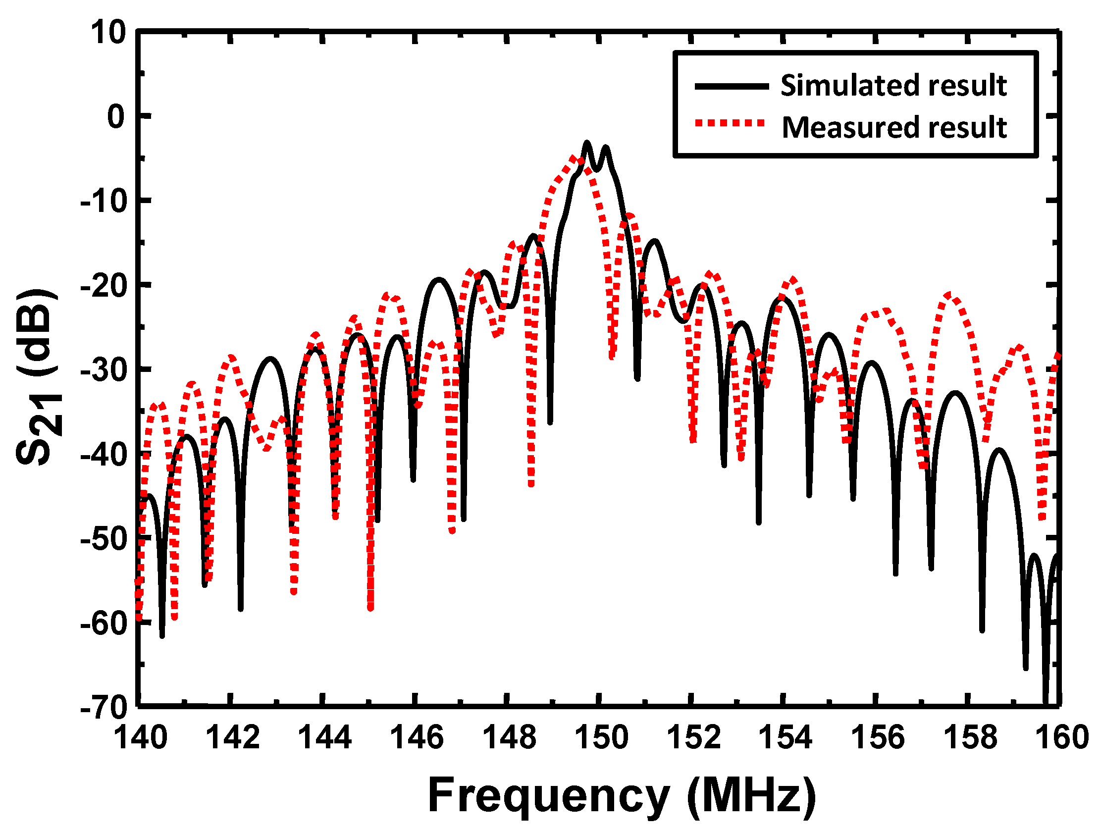
where Y11, Y12, Y21 and Y22 are the elements of admittance matrix deduced by cascading the P-matrix of SPUDTs. Y01 and Y02 denotes the characteristic admittance of signal ports. Figure 5 shows the computed response characteristics (S21) of the Love wave devices with an operation frequency of 150 MHz. The corresponding device structure consists of two 300 nm Al-SPUDTs with lengths of 196λ (~26 μm) and 60λ. The acoustic aperture and guiding SiO2 overlay thickness are set to 100λ and 5 μm, respectively.
3. Technique Realization
3.1. Love Wave Devices
3.1.1. SH-SAW Delay Line Preparation
As mentioned in Figure 1b, the proposed Love wave sensing device was composed of a SH-SAW delay line pattern on 36° YX LiTaO3 substrate with a SiO2 guiding layer, and a sensitive layer on top of the SiO2. First, a 150 MHz SH-SAW delay-line configuration was defined was fabricated photolithographically on a 36° YX LiTaO3 wafer. Two aluminum (Al) SPUDTs were separated by a path length of 2.5 mm. The corresponding wavelength, λ, is calculated though dividing the velocity by operation frequency as 26 μm. The electrode widths in SPUDTs are 6.5 μm (λ/4) and 3.25 μm (λ/8), respectively. The corresponding fabrication procedure is described below. Aluminum with thickness of 150 nm was deposited on the cleaned LiTaO3 substrate surface using a e-beam evaporation. Then, a 1-mm-thick photoresist (PR) was spin-coated, exposed, and developed for the delay line patterns. Al was wet-etched and PR was dissolved in acetone. Several rinses with DI water were performed to remove any unwanted products.
3.1.2. SiO2 Guiding Layer Deposition
The SiO2 guiding layer with various thicknesses was deposited on the entire surface of the prepared patterned LiTaO3 wafer by ion-assisted e-beam evaporation. High-purity (99.99%) SiO2 target and vacuum degree of 10−4 Pa were utilized. The ion energy in ion-assist is adjusted to 120 eV, and the efficiency in evaporation is set to 1 nm/s. To prevent breakage of the piezoelectric substrate in the process of thicker SiO2 deposition over 200 °C, the e-beam evaporation was used for thicker SiO2 deposition at room temperature of 25 °C. The prepared SiO2 overlay with thickness of ~5 μm was characterized by AFM, the corresponding AFM picture indicates satisfactory quality of the SiO2 coating as good uniformity and less surface pollution, as shown in Figure 6.
3.1.3. Love Wave Device Characterization
The frequency response (S21) of the Love wave device was characterized by using the network analyzer as shown in Figure 6. Lower insertion of less than 5 dB was observed thanks to the waveguide effect and SPUDTs structure, which is in accordance with the theoretical prediction. Also, the temperature characteristic of the proposed Love wave device was performed by measuring its corresponding frequency response at various temperatures, as shown in Figure 7. It denotes that excellent temperature stability (TCF of 10 ppm/°C) was achieved by using the strategic guiding structure over the SH-SAW device on 36° YX LiTaO3 (39.8 ppm/°C).
3.2. Sensing Material Preparation
The CrypA employed for sensing CH4 was synthesized from vanilline by a so-called two-step method [11]. The CrypA solution was prepared prior to conducting the gas experiment. The polyvinyl chloride (PVC) and dioctyl sebacate (DLS) was used as the crosslinker to create covalent bonds among the CrypA molecules, while the tetrahydrofuran (THF) was utilized as the solvent. The detailed composition in CrypA solution is that 3.0 mg CrypA, 0.3 mg PVC and 0.6 mg DLS were dissolved in 2 mL THF. Prior to the CrypA deposition, the SiO2 surface of the sensing SAW device was cleaned by a routine cleaning procedure involving rinsing in piranha solution (H2SO4 − H2O2 = 3:1 v/v), a DI water rinse and drying by N2. Then, 0.3 μL CrypA solution was dropped on the cleaned SiO2 layer surface between the transducers of the sensing device, and then cured at 80 °C for 40 min in an oven.
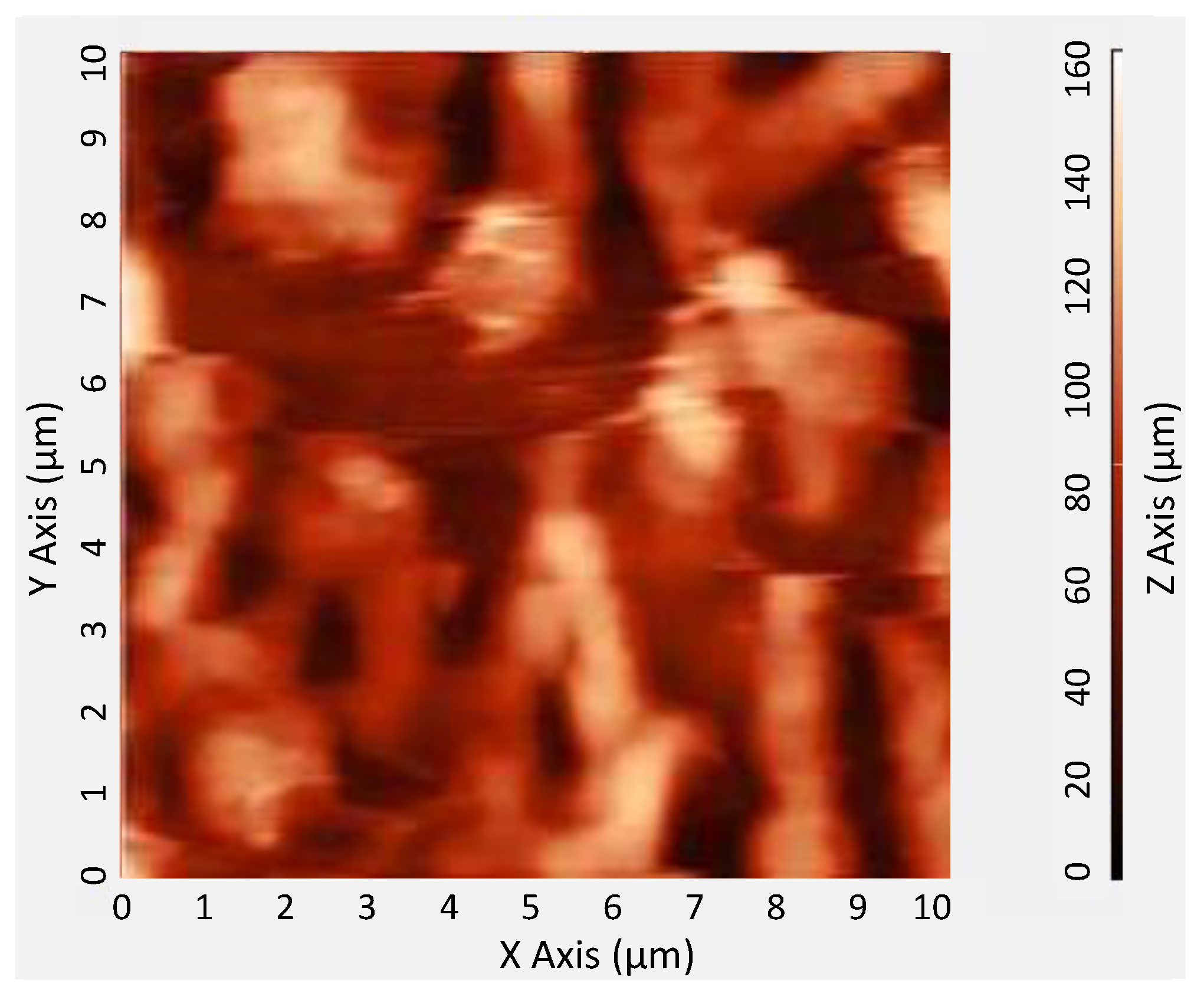
The surface topography of coated CrypA was characterized by the atomic force microscope (AFM), as shown in Figure 8. It is obviously that it has a rough surface with many fluctuations and bubbles, which is beneficial for gas sensing.
3.3. Differential Oscillator Configuration
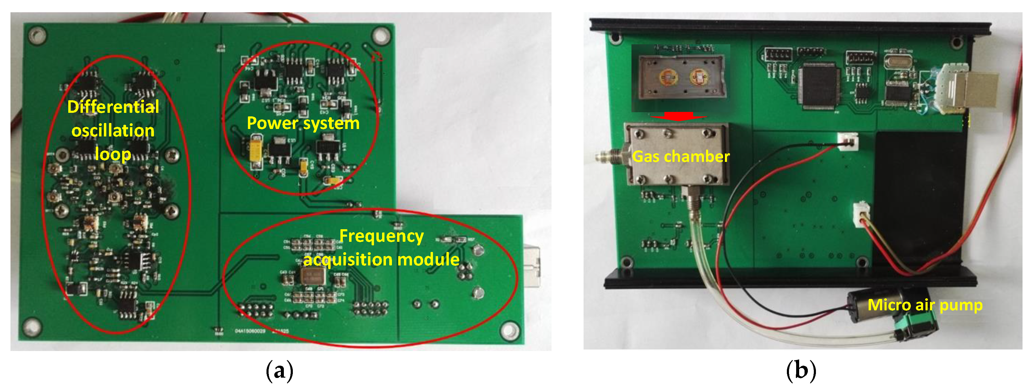
To build the sensor system, the prepared CrypA coated Love wave device and a uncoated device as reference were connected into the differential oscillation loop depicted in Figure 9a, which was composed of amplifiers, phase shifters, and mixer. The differential frequency signal was picked by the FPGA based frequency acquisition module (FSM), and recorded and plotted by the PC. The prepared sensing devices were embedded into the nickel-plated Al-gas chamber with volume of 500 mL (Figure 9b). The gas in the air bags can be pumped into the gas chamber inside by an atmosphere sampler and a micro air pump. The corresponding PCB for the sensor system is shown in Figure 9.
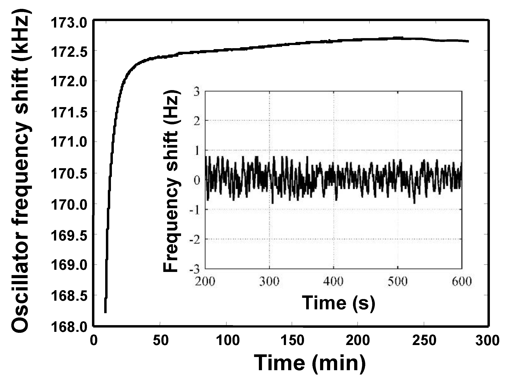
Obviously, the frequency stability of the oscillator affects directly the detection limit and stability of the sensor system, hence, a measurement on the frequency stability of the oscillator was conducted, as shown in Figure 10. After 20 min, the sensor reached a relatively stable state, and excellent short-term (in second) and medium-term (in hours) frequency stability were achieved as ±1 Hz/s and ±10 Hz/h.
4. Discussion Experimental Results and Discussions
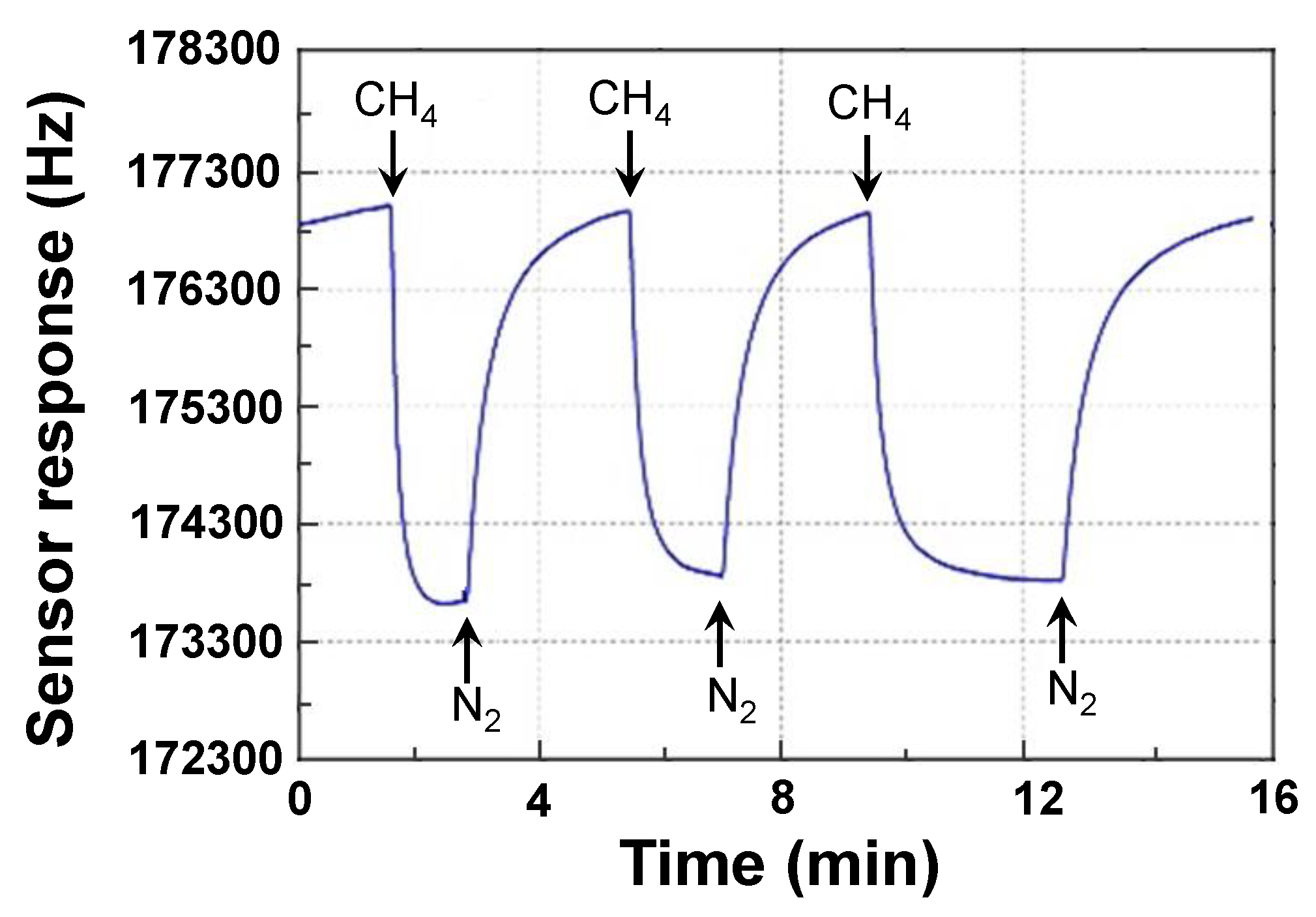
Using the experimental setup composed of the proposed sensor system, air bags, hygrometer, thermometer, and PC, the Love wave sensing devices were characterized, as shown in Figure 11. First, the repeatability of the CrypA coated Love wave device was evaluated, as shown in Figure 12, that is a response profile obtained from the three consecutive 3 min on-off exposure to 5% CH4 in pure N2 at temperature/humidity of 25 °C/50% RH using the prepared Love wave sensing device. Excellent reproducible run was observed from the three gas exposures. Also, the picked sensor signal rises rapidly upon exposure to 5% CH4 and reaches the equilibrium value in 15 s, and then returns to its initial status within 20 s after removing the CH4. It means fast response time and recovery time with good repeatability were achieved from the developed Love wave sensor prototypes at room temperature.
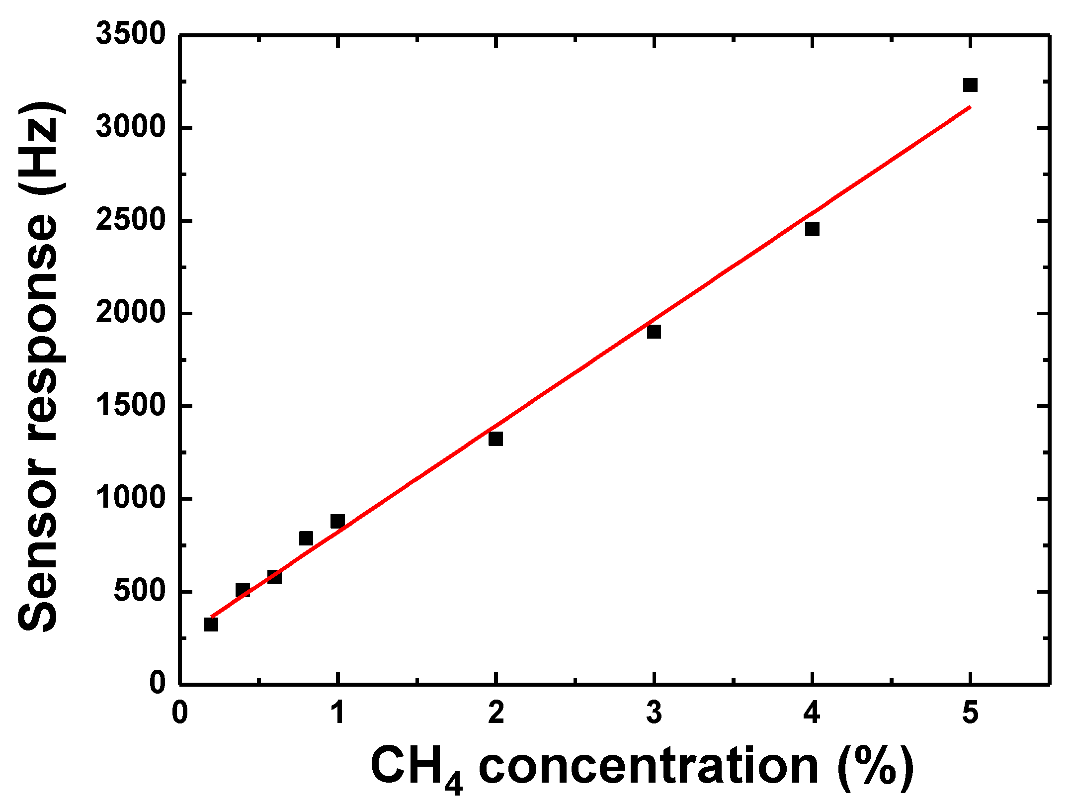
Figure 13 shows the sensor response at various CH4 concentration. It can be seen that the response is quite linear at CH4 concentrations of 0.1~5%, and the fitted slope is ~624 Hz/%, which is three times that of a similar sensor using R-SAW [10]. Also, a relatively high response of ~280 Hz is observed from the proposed Love wave sensing device upon exposure to 0.1% CH4, which means that a low detection limit of 0.005% is expected when a linear response was assumed at lower concentrations according to the International Union of Pure and Applied Chemistry (IUPAC) [6] norms.
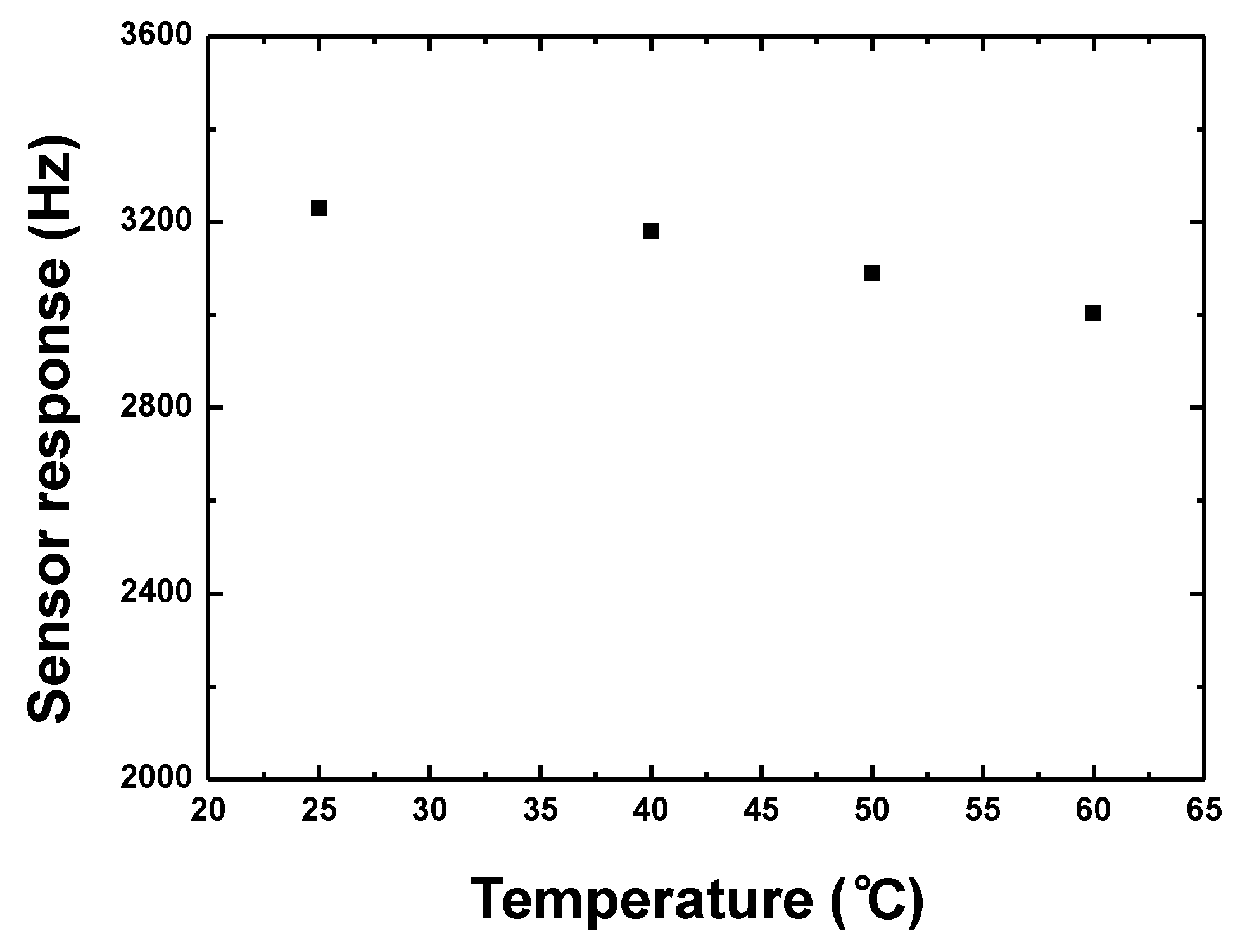
Also, the proposed sensor was characterized after exposure to 5% CH4 at various temperatures controlled by using a heating table to evaluate the temperature stability, as shown in Figure 14. Obviously, with increase of testing temperature, the sensor response towards 5% CH4 decreases. The response fluctuation is 6% from 25 °C to 60 °C, and only 0.2 %/°C thanks to the differential oscillation structure and self-compensated sensing device configuration. The reason for the response fluctuation arises from the non-zero Tcf of the Love wave device itself, CrypA thin-film and the active electronic components in the oscillation loop.
5. Conclusions
This work presents a new Love wave-based device for sensing methane gas, in which, a CrypA thin-film exhibits excellent sensor response, and the Love wave device provides a larger mass sensitivity and superior temperature stability. Using FEM analysis, the coupling of modes (COM) parameters were extracted for Love wave sensing device simulation prior to fabrication. The CrypA was synthesized by a typical two-step method, and coated onto the wave propagation path by using a dropping method. The developed Love wave sensing device was connected to a differential oscillation loop, and characterized in gas exposure experiments. High sensitivity, fast response, and excellent temperature stability were achieved at room temperature. Obviously, the proposed Love wave device features higher sensitivity compared to Rayleigh wave mode devices.
Author Contributions
All authors participated in the work presented here. W.W. and Y.P. proposed the original idea and defined research topic; S.F. and S.H. conducted the Love wave device simulation; Y.J. and Y.L. performed the device development and experiments; C.Z. and C.D. synthesized the gas-sensitive materials used in this work.
Funding
This research was funded by National Natural Science Foundation of China grant number [11774381].
Acknowledgments
This work is supported by the project of knowledge innovation project of the institute of acoustics, Chinese Academy of Sciences, Key Research Program of the Chinese Academy of Sciences (QYZDY-SSW-JSC007).
Conflicts of Interest
The authors declare no conflict of interest.
References
- Rana, L.; Gupta, R.; Tomar, M. ZnO/ST-Quartz SAW resonator: An efficient NO2 sensor. Sens. Actuators B 2017, 252, 252–257. [Google Scholar] [CrossRef]
- Marcu, A.; Viespe, C. Surface acoustic wave sensors for Hydrogen and Deuterium detection. Sensors 2017, 17, 1417. [Google Scholar] [CrossRef] [PubMed]
- Raj, V.B.; Tomar, M.; Nimal, A.T. Nano-crystalline SnO2 thin film based surface acoustic wave sensor for selective and fast detection of NO2 gas. Adv. Sci. Lett. 2014, 20, 1124–1128. [Google Scholar] [CrossRef]
- Wang, S.H.; Wang, C.Y.; Shen, C.Y.; Zhi, J.L. Nitric oxide sensing properties of a surface acoustic wave sensor with copper-ion-doped polyaniline/tungsten oxide nanocomposite film. Sens. Actuators B 2017, 243, 1075–1082. [Google Scholar]
- Asad, M.; Sheikhi, M.H. Surface acoustic wave based H2S gas sensors incorporating sensitive layers of single wall carbon nanotubes decorated with Cu nanoparticles. Sens. Actuators B 2014, 198, 134–141. [Google Scholar] [CrossRef]
- Wang, W.; He, S.T.; Li, S.Z. Enhanced Sensitivity of SAW Gas Sensor Coated Molecularly Imprinted Polymer Incorporating High Frequency Stability Oscillator. Sens. Actuator B 2007, 125, 422–427. [Google Scholar]
- Wohltijon, H.; Ressy, R. Surface Acoustic Wave Probe for Chemical Analysis: part I—Instruction and Instrument Description, part II—Gas Chromatography Detector. Anal. Chem. 1979, 51, 1458–1469. [Google Scholar] [CrossRef]
- Souteyrand, E.; Nicolas, D.; Martin, J.R.; Chauvet, J.P.; Perez, H. Behaviour of cryptophane molecules in gas media. Sens. Actuators B 1996, 33, 182–187. [Google Scholar] [CrossRef]
- Garel, L.; Dutasta, J.P.; Collet, A. Complexation of methane and chlorofluorocarbons by cryptophane-A in organic solution. Angew. Chem. Int. Ed. Engl. 1993, 32, 1169–1171. [Google Scholar] [CrossRef]
- Wang, W.; Hu, H.L.; He, S.T.; Pan, Y.; Zhang, C.H.; Dong, C. Development of a room temperature SAW methane gas sensor incorporating a supramolecular cryptophane a coating. Sensors 2016, 16, 73. [Google Scholar] [CrossRef] [PubMed]
- Caniceill, J.; Collet, A. Two step synthesis of D3 and C3h cryptophanes. J. Chem. Soc. Chem. Commun. 1988, 9, 582–584. [Google Scholar] [CrossRef]
- Sun, P.; Jiang, Y.D.; Xie, G.Z. A room temperature supramolecular quartz crystal microbalance (QCM) methane gas sensor. Sens. Actuators B 2009, 141, 104–108. [Google Scholar] [CrossRef]
- Khoshaman, A.H.; Li, P.C.H.; Merbouh, N. Highly sensitive supra-molecular thin films for gravimetric detection of methane. Sens. Actuators B 2012, 161, 954–960. [Google Scholar] [CrossRef]
- Sayago, I.; Matatagui, D. Graphere oxide sensitive layer in Love-wave surface acoustic wave sensors for the detection of chemical warfare agent stimulants. Talants 2016, 146, 393–400. [Google Scholar] [CrossRef] [PubMed]
- Dejous, C.; Hallil, H.; Raimbault, V. Love acoustic wave-based devices and molecularly imprinted polymers as versatile sensors for electronic nose or tongue for cancer monitoring. Sensors 2016, 16, 915. [Google Scholar] [CrossRef] [PubMed] [Green Version]
- Zimmermann, C.; Rediere, D.; Dejous, C. Detection of GB and DMMP Vapors by Love Wave Acoustic Sensors Using Strong Acidic Fluoride Polymers. IEEE Sens. J. 2004, 4, 479–488. [Google Scholar] [CrossRef]
- Wang, W.; Xie, X.; Chen, G.; He, S.T. Temperature-compensated Love wave based gas sensor on waveguide structure of SiO2/36° LiTaO3. Smart Mater. Struct. 2015, 24, 065019. [Google Scholar] [CrossRef]
- Xu, F.Q.; Wang, W.; Hou, J.L.; Liu, M.H. Temperature Effects on the Propagation Characteristics of Love Waves along Multi-Guide Layers of SiO2/Su-8 on ST-90°X. Quartz. Sensors 2012, 12, 7337–7349. [Google Scholar] [CrossRef] [PubMed]
- Wang, W.; He, S.T.; Liu, M.H.; Pan, Y. Advances in SXFA-Coated SAW Chemical Sensors for Organophosphorous Compound Detection. Sensors 2011, 11, 1526–1541. [Google Scholar] [CrossRef] [PubMed] [Green Version]
Figure 1.
The schematic of SAW based gas sensor (a) and Love wave based sensor (b).

Figure 2.
(a) supramolecular interactions of CrypA towards CH4 and (b) synthesis of cryptophane-A.

Figure 3.
FEM analysis on Love wave devices (a) waveguide structure of SiO2/Al electrodes/36° YX LiTaO3; (b) Meshing structure and (c) Love wave displacement profile.
Figure 3.
FEM analysis on Love wave devices (a) waveguide structure of SiO2/Al electrodes/36° YX LiTaO3; (b) Meshing structure and (c) Love wave displacement profile.

Figure 4.
The calculated COM parameters varying with SiO2 thickness: (a) velocity; (b) static capacitance; (c) excitation coefficient and (d) coupling coefficient.
Figure 4.
The calculated COM parameters varying with SiO2 thickness: (a) velocity; (b) static capacitance; (c) excitation coefficient and (d) coupling coefficient.

Figure 5.
The simulated and measured response characteristics of the proposed Love wave device.

Figure 6.
The AFM characterizing picture of the prepared SiO2 overlay, (a) surface characteristic; and (b) thickness measurement.
Figure 6.
The AFM characterizing picture of the prepared SiO2 overlay, (a) surface characteristic; and (b) thickness measurement.

Figure 7.
The measured temperature stability of the Love wave device.

Figure 8.
Surface topography description of the CrypA by AFM.

Figure 9.
(a) The differential oscillation loop and (b) integrated sensor system.

Figure 10.
Frequency stability test of the proposed sensor system.

Figure 11.
The experimental setup for characterizing the proposed Love wave sensor.

Figure 12.
The repeatability test of the proposed sensor upon exposure to 5% CH4.

Figure 13.
The sensitivity evaluation of the proposed Love wave sensor.

Figure 14.
The temperature stability testing of the proposed sensor upon exposure to 5% CH4.


Table 1.
The COM parameters of the Love wave device at optimum SiO2 thickness of 0.23.
| COM Parameters | Values | COM Parameters | Values |
|---|---|---|---|
| SAW velocity (m/s) | 3962.08 | Normalized excitation coefficient | 0.0196 |
| Normalized coupling coefficient (Ω−1/2) | 4.7628 × 10⁻⁴ | Normalized static capacitance (F/m) | 4.6736 × 10⁻¹⁰ |
© 2018 by the authors. Licensee MDPI, Basel, Switzerland. This article is an open access article distributed under the terms and conditions of the Creative Commons Attribution (CC BY) license (http://creativecommons.org/licenses/by/4.0/).
Share and Cite
MDPI and ACS Style
Wang, W.; Fan, S.; Liang, Y.; He, S.; Pan, Y.; Zhang, C.; Dong, C. Enhanced Sensitivity of a Love Wave-Based Methane Gas Sensor Incorporating a Cryptophane-A Thin Film. Sensors 2018, 18, 3247. https://doi.org/10.3390/s18103247
AMA Style
Wang W, Fan S, Liang Y, He S, Pan Y, Zhang C, Dong C. Enhanced Sensitivity of a Love Wave-Based Methane Gas Sensor Incorporating a Cryptophane-A Thin Film. Sensors. 2018; 18(10):3247. https://doi.org/10.3390/s18103247
Chicago/Turabian StyleWang, Wen, Shuyao Fan, Yong Liang, Shitang He, Yong Pan, Caihong Zhang, and Chuan Dong. 2018. "Enhanced Sensitivity of a Love Wave-Based Methane Gas Sensor Incorporating a Cryptophane-A Thin Film" Sensors 18, no. 10: 3247. https://doi.org/10.3390/s18103247
Note that from the first issue of 2016, this journal uses article numbers instead of page numbers. See further details here.