The Investigation of a Shape Memory Alloy Micro-Damper for MEMS Applications

Department of Mechanical Engineering, Inha University, Incheon, 402-751, South Korea
*
Author to whom correspondence should be addressed.
Sensors 2007, 7(9), 1887-1900; https://doi.org/10.3390/s7091887
Submission received: 6 August 2007
/
Accepted: 10 September 2007
/
Published: 11 September 2007
(This article belongs to the Special Issue Modeling, Testing and Reliability Issues in MEMS Engineering)
Abstract
:Some shape memory alloys like NiTi show noticeable high damping property in pseudoelastic range. Due to its unique characteristics, a NiTi alloy is commonly used for passive damping applications, in which the energy may be dissipated by the conversion from mechanical to thermal energy. This study presents a shape memory alloy based micro-damper, which exploits the pseudoelasticity of NiTi wires for energy dissipation. The mechanical model and functional principle of the micro-damper are explained in detail. Moreover, the mechanical behavior of NiTi wires subjected to various temperatures, strain rates and strain amplitudes is observed. Resulting from those experimental results, the damping properties of the micro-damper involving secant stiffness, energy dissipation and loss factor are analyzed. The result indicates the proposed NiTi based micro-damper exhibits good energy dissipation ability, compared with conventional materials damper.
1. Introduction
Shape memory alloy (SMA) is considered as one promising material due to its large deformation recovery ability and high ultimate tensile strength as well. Most SMA materials show distinct behaviors, including shape memory effect (SME), pseudoelasticity effect (PE, also known as superelasticity effect) and high damping capacity [1-3].
A shape memory alloy is capable of recovering its original shape after large deformation by heating above its characteristic transition temperature (SME) or by releasing applied loads (PE). Although the shape memory effect of SMAs exhibits higher damping capacity and larger recoverable deformation than pseudoelasticity effect, the time lag phenomenon and requirement for temperature control limit it to be used for practical applications. Hence the investigations of most previous researchers focus on the pseudoelasticity effect for passive vibrations control rather than shape memory effect.
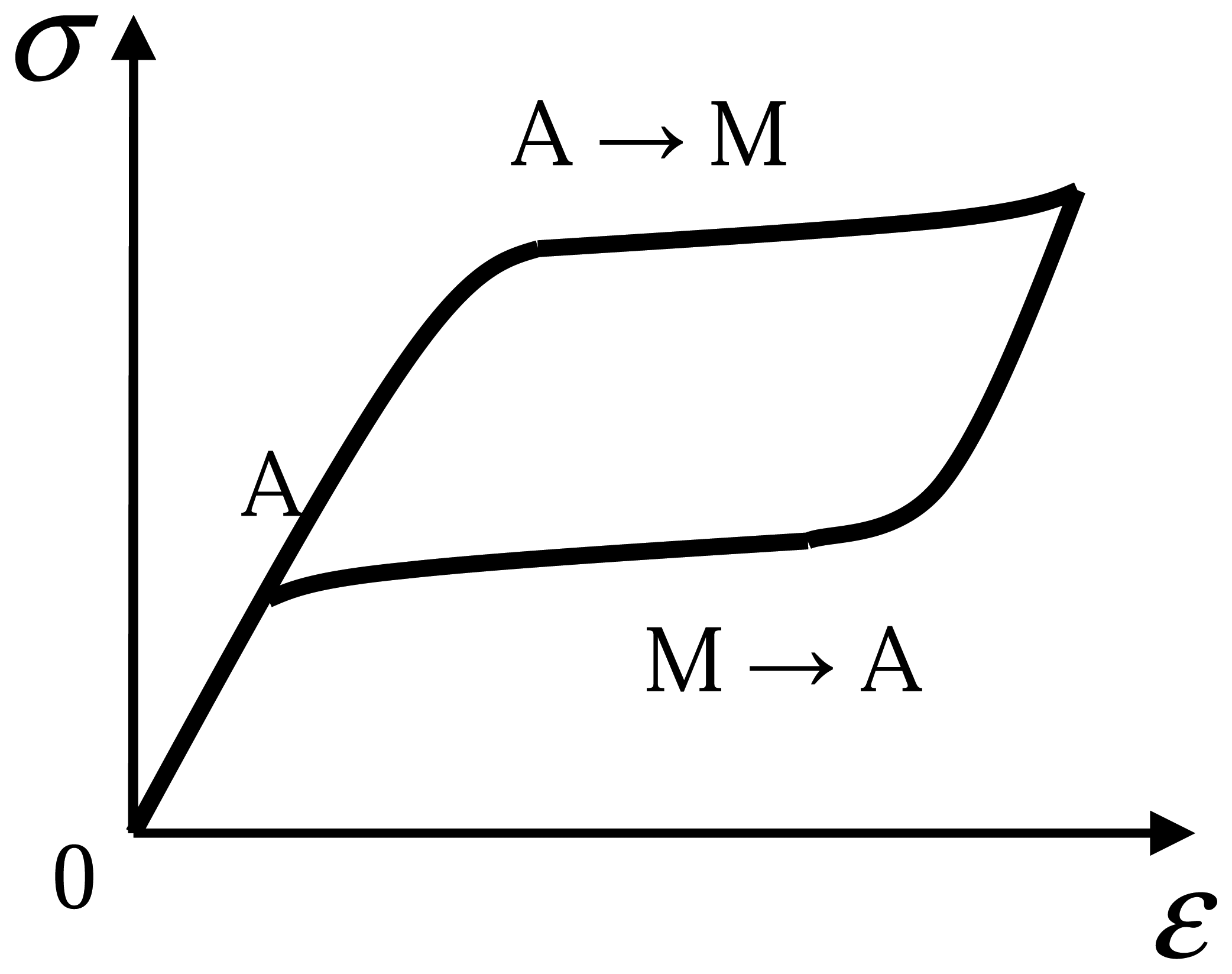
In nature, the phenomenon of pseudoelasticity effect results from the phase transformation above austenite finished temperature Af[4]. When the applied stress reaches a critical value, the austenite SMA material begins to transform to martensite phase; once the loading is released, the stress induced martensite SMA returns to austenite phase without residual strain [5]. As a result, one hysteresis loop can be formed by a closed stress-strain curve in the whole loading-unloading process, as shown in figure 1. This hysteresis loop, however, is called the energy dissipation capacity and indicates the conspicuous damping property of SMA materials [6-7].
Ascribing to its high damping capacity and implicit characteristics, austenite SMA wire shows great potential to be used as passive vibration element [3, 8-10]. The recoverable deformation of SMA is up to 6-8%. The energy dissipation capacity is much higher than the other conventional materials such as steel and concrete. In addition, it owns exceptional high fatigue and corrosion resistance. Without degradation due to ageing effect, the SMA shows great durability as an engineering material. Due to the fabrication technology and low cost, a Nitinal (NiTi) alloy has become the most prevalent shape memory alloy for commercial applications [11].
Attributed to those conspicuous mechanical properties, various SMA applications are invented and developed in automotive, aerospace, civil engineering, medical field and so on [4, 12]. Associated with the rapid development of batch fabrication and integration technology, SMAs are receiving special attentions for the MicroElectroMechanical systems (MEMS) applications nowadays. So far, thin films are considered as the primary choice of SMA material for MEMS devices. SME phenomenon, high power to weight ratio, large achievable strain and low driving voltage make SMA based MEMS devices attractive. Some MEMS applications involving SMA are micro-sensors, micro-actuators, micro-grippers, micro-pumps and so on [11, 13-19]. However, the bulk SMA materials like thin wires are also found available for potential MEMS applications [20-21].
In this study, a NiTi wire based micro-damper is proposed by utilizing the pseudoelasticity behavior of SMA. Though not standard, this damper may also be considered as a MEMS device since its dimensions are similar to typical MEMS products. The potential utilization of this product may be expected as the actuation means of the micro-gripper, the joint component of robotic and micro-actuators, or energy absorber for suspension system of automobile and structures/machines.
2. Design of the Micro-damper Model
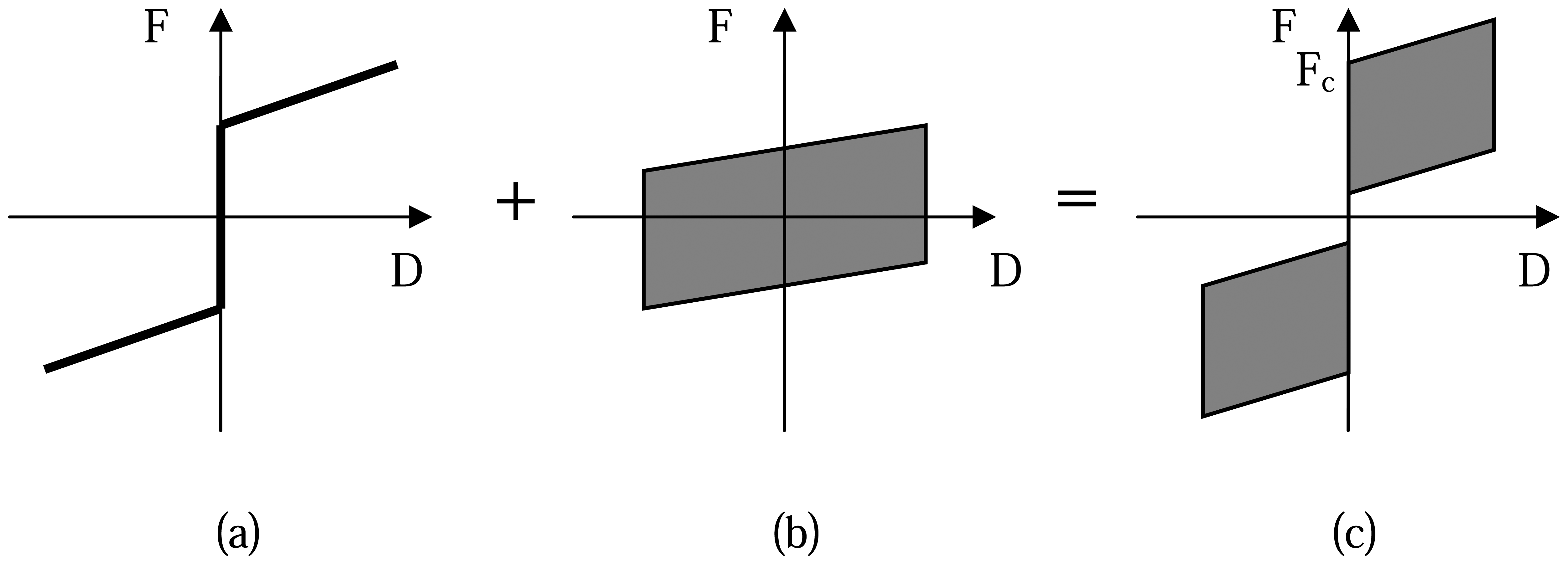
This SMA micro-damper model aims at high energy dissipation and complete deformation recovery ability as well. Nevertheless, these two targets are somewhat inconsistent because energy dissipation requires a hysteresis loop formed by force-displacement curve while the latter one can be satisfied by passing though the original point only. In order to realize it, Dolce's model [22] is adopted in this study, as shown in figure 2. However, it is observed the hysteresis loop of SMA schematically shown in figure 2(b) does not closely coincide with the behavior of energy dissipation element in Dolce's model. The maximum force increases with increasing displacement when the damper is pulled, while decreases when it is pushed.
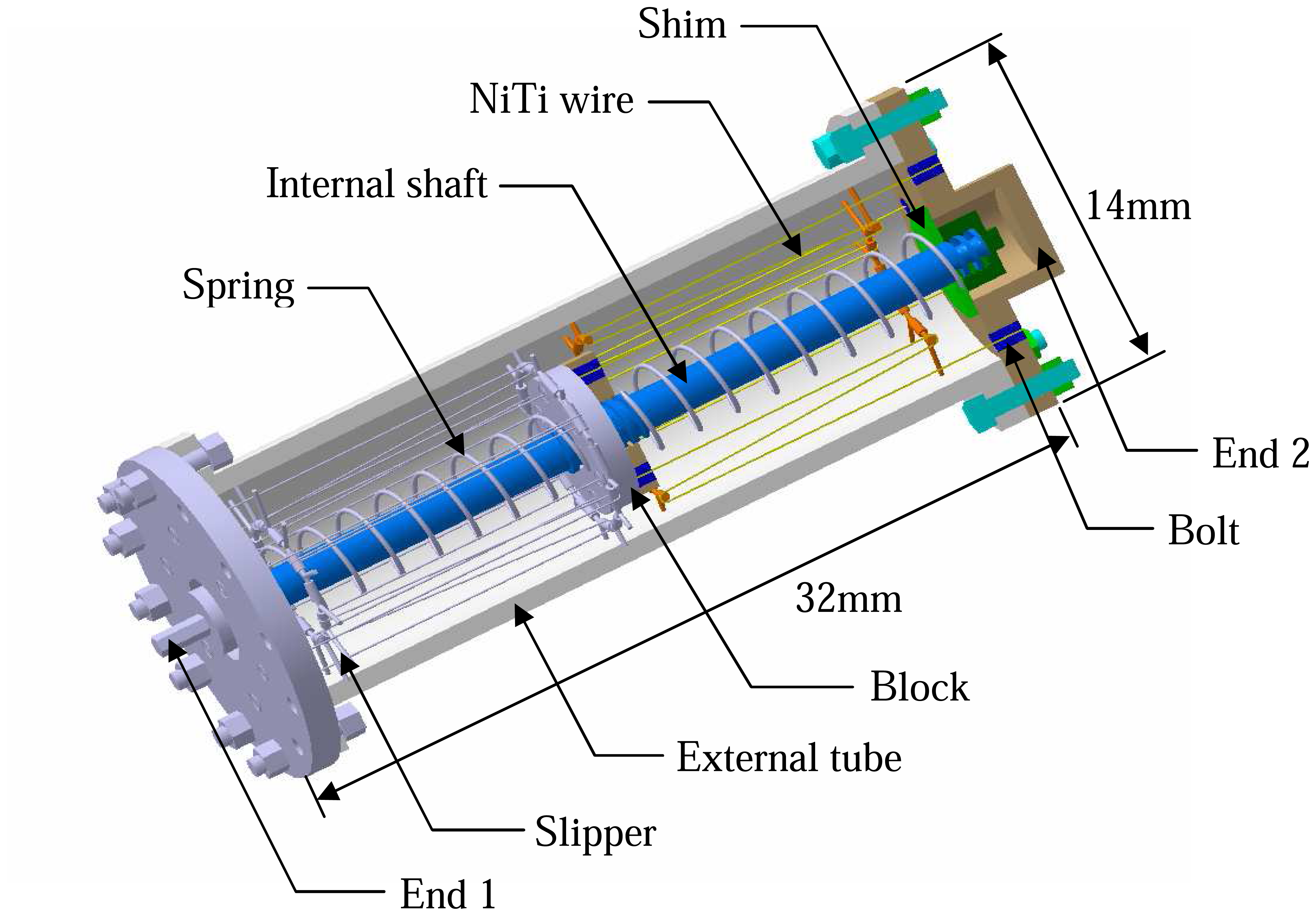
The prototype of conceptual SMA micro-damper is shown in figure 3. The main components of this damper consist of internal shaft, external tube, blocks, shims, springs, slippers and NiTi wires. The length of the damper is designed as 32mm and the diameter is 14mm for special study purpose here. The diameter of NiTi wires is 0.14mm and its free length is 35mm.
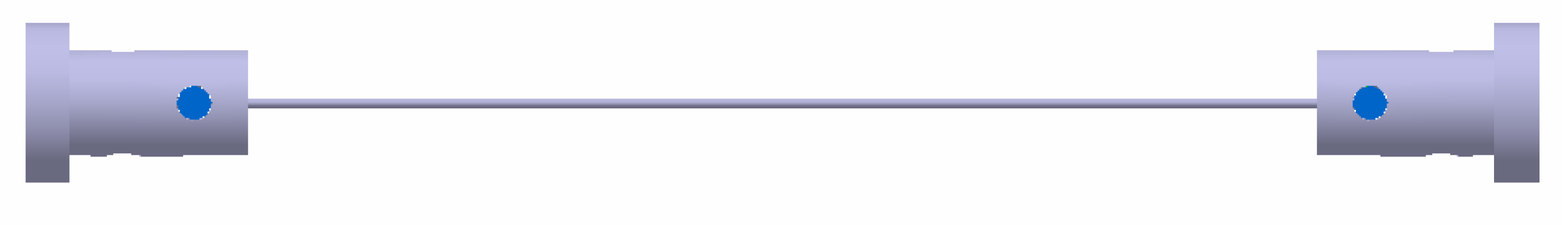
The NiTi wires, however, are heat treated after manufacturing and the oxidized layer is removed from the surface in order to obtain high strength, good corrosion and wear resistance. While this causes the general methods like welding and screwing cannot be adopted properly to install the wires in the damper assembly. Hence a new method on how to fix wires mechanically is suggested, as shown in figure 4.
The main body of the micro-damper is modeled symmetric. The damper ends are connected with internal shaft (End 1) and external tube (End 2) respectively to transfer the applied force. The NiTi wires are mechanically fixed by bolts and connected to shaft and tube at end 1 and end 2, respectively. Two compressed springs are inserted between the blocks and shims separately. The blocks are put around internal shaft at the center and the shims work as bridge to connect the springs with internal shaft and external tube. Two pairs of slippers are fixed on external tube to enlarge the stroke of the damper, i.e. the recoverable deformation. To enhance the fatigue life of damper, the diameter of the slipper is designed much larger than NiTi wires [23] and the wires are wound around the slipper with an acute angle, as shown in figure 5. Furthermore, to improve energy dissipation and self-centering of the damper, the NiTi wires are installed with 3% pre-strain. Since this damper is designed for devices under unidirectional movements, only axial loads are supported by it.
The initial configuration of micro-damper before loading is shown in figure 6(a). The NiTi wires are stretched by the block and the external tube. The reaction force to this compression of spring on one side of the spring is supplied by internal shaft via block, while it is provided by both shaft and tube on the other side. For better understanding, these behaviors are schematically indicated by the arrows in the figure.
When the micro-damper is pushed by an external load F, the movement of internal shaft is restricted until the applied load exceeds the critical force Fc, shown in figure 2(c). This movement restriction modifies the force distribution in shaft and tube on the right side of damper. The schematic diagram of the force transferred from left end (shaft) to right end (tube) is displayed by the arrows in figure 6(b). At this stage, all the forces applied to the shim, on right side, are sustained by the tube only. In accordance with the movement of damper, the NiTi wires on left side are stretched while contracted on the right side. However, all the wires are still in tension. It can be obviously observed in figure 2(b) that the deformation of NiTi wires does not vanish completely after the load is released. This residual deformation creates a differing force carried by the two springs, which, however, compels the damper to recover its original shape after unloading.
Similar behavior may be observed during tensile loading-unloading process. Through the mechanical loading-unloading cycles working in the pseudoelastic range, the phase of SMA wires is transformed from martensite to austenite, then returns to martensite. During the phase transformation, the energy may be dissipated by the conversion from mechanical to thermal energy, resulting in the reduction of vibration of structures or devices.
3. Experimental Observation of NiTi Wires
As the kernel component of the micro-damper, the damping behavior of the NiTi wires should be exploited prior to the possible realization of the assembly. Some experimental phenomena have been observed by previous researchers and the results indicate that the damping property of NiTi wires is of obvious dependence on the environment and loading conditions, such as composition, geometry, temperature, strain rate and amplitude etc [24-27]. Hence the NiTi wire with various diameters should be specially investigated for different purposes.
3.1 Specimen
The NiTi wires with nearly equi-atomic composition are selected for experiment observation here. The free length of SMA wires is chosen as 35mm for test. The transformation temperatures are Mf = 243K, Ms = 255K, As = 271K, Af = 284K respectively.
3.2 Influence of loading-unloading cycles
It has been revealed that the first several decades of loading-unloading cycles can influence the mechanical behavior of NiTi wires significantly, while it turns stable with negligible reduction as the loading-unloading cycle number increases [6, 10, 24-25]. Figure 7 shows pseudoelasticity phenomenon of NiTi wire and illustrates its mechanical behavior is not sensitive to cyclic effect after 100 cycles. As a result, a series of experimental work for NiTi wires with 100 cycles training is conducted under uniaxial tensile loads with various temperatures, strain rates, strain amplitudes.
3.3 Influence of temperatures
The experiment for mechanical behavior of NiTi wires in low strain rate 1×10⁻³s-1 is carried out at various temperatures of 287, 294, 301 and 308K. The surface temperature of wires is kept constant during the tests.
Observed from figure 8, the start transformation stress of martensite, i.e. the critical stress, occurs when the strain reaches 0.65-0.9% at different temperature and large hysteresis loops appear during whole loading-unloading process. Obviously, the increase of temperature causes the rise of transformation stress from austenite to martensite phase. Moreover, the area surrounded by hysteresis loop is not significantly changed with temperature, meaningfully denoting the dissipated energy may be considered as temperature independent during this temperature range. This phenomenon is considered to ascribe to the small size of the wire. Due to the thin diameter of wire, the heat generated by the applied loads may be dissipated very quickly; therefore the influence of temperature on energy dissipation is negligible.
3.4 Influence of strain rates
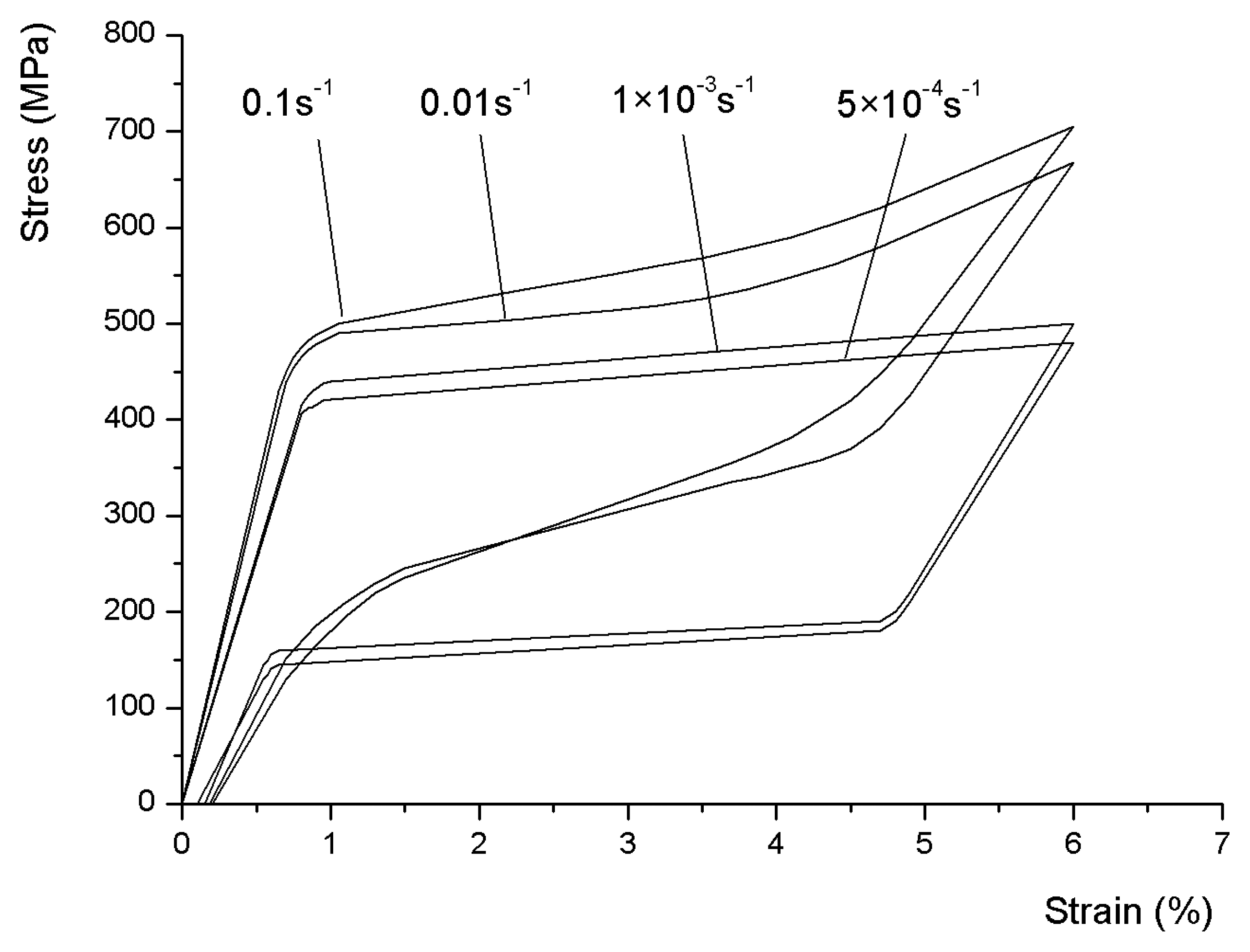
The stress-strain curves are obtained under strain rates of 5×10⁻⁴, 1×10⁻³, 0.01 and 0.1s-1 respectively at constant temperature of 294 K, as shown in figure 9.
It is observed that the mechanical behavior of the wires changes significantly with the variation of strain rates. As can be seen, both upper and lower stress plateaus, which correspond to forward and reverse martensite transformation respectively, increase with increasing strain rates. In the viewpoint of energy, this behavior is ascribed to the heat exchange between wires and ambient air. When strain rate is low, the wire is acted by quasi-static tensile force; therefore the heat generated during loading-unloading process is able to be dissipated immediately. Nevertheless, high strain rate causes the reduction of dissipated heat in unit time, leading to the accumulation of the heat. Hence the instantaneous temperature of wire is higher than isothermal, resulting in the rise of the upper and lower stress plateaus.
Moreover, it is found the increasing strain rate causes the appearance of steep inverse phase transformation curve and narrow hysteresis loop, leading to the reduction of energy dissipation capacity.
3.5 Influence of strain amplitudes
The stress-strain curves obtained with various strain amplitudes of 3, 4, 5 and 6% under constant temperature of 294K and low strain rate of 1×10⁻³s-1 are shown in figure 10.
The result shows the transformation stress of NiTi wires, as well as the upper and lower stress plateaus, is almost not varied with the strain amplitude. Obviously, the dissipated energy rises significantly with increasing amplitudes. However, the increasing amplitudes may lead to the accumulation of residual strain of the wire after complete unloading.
4. Analysis of the SMA Micro-damper
Based on the experimental results of NiTi wires obtained above, the damping property of the proposed micro-damper model may be assessed prior to realization. For this purpose, three mechanical quantities, involving secant stiffness Ks, energy dissipation ΔW and loss factor η, are mainly considered in this study.
The secant stiffness may be calculated as
where Fmax and Fmin are maximum and minimum forces respectively and δmax and δmin maximum and minimum displacements [28].
The loss factor η, as the effective parameter to measure the damping ability of the device, is defined as the specific damping capacity per radian of the damping cycle [25].
As the recentering element, the material of the spring is 60Si2Mn steel. And other components are made of steel. The material strength and fatigue of all these elements are estimated. Six pieces of 100 pre-cycle training NiTi wires in each side are installed in the device. The initial compression force of each spring is 55N when the damper is not applied by external loads.
The mechanical behavior of conceptual designed damper subjected to different temperatures is shown in figure 12. The hysteresis loop of the full functional device in one complete tension-compression cycle is schematically shown in figure 12(a), formed by force-displacement curve. Observed from figure 12(b), the secant stiffness of the damper is increased around 2% in every other 7K temperature. The energy dissipation amount and corresponding loss factor in one cycle are calculated and drawn in figure 12(c). Judged from the curve, this damping device dissipates a bit more energy at higher temperature. This phenomenon seems conflicting to the conclusion on temperature influence to a single NiTi wire while it is still reasonable. By taking a few pieces of wires into account, the influence of temperature to the energy dissipation of the damper cannot be ignored as the single wire, though the variation of energy dissipation is not significant. Moreover, it is observed the loss factor slightly varies from 0.085 to 0.092 associated with increasing temperatures, indicating the energy dissipation ability of this device is not strongly dependent on temperature variation.
Figure 13 shows the mechanical behavior of damper subjected to different working strain rates. Unlike the force-displacement curve in low strain rate, the one in high strain rate exhibits narrow hysteresis loop, as shown in figure 13(a). Figure 13(b) shows the secant stiffness increases 16% when the working strain rate rises from 5×10⁻⁴s-1 to 0.1s-1. The dissipated energy, shown in figure 13(c), descends steeply up to 0.01s-1, whereas increases slightly from 0.01s-1 to 0.1s-1. However, the loss factor of the device decreases as the strain rate increases, though not significant as the strain rate is larger than 0.01s-1.
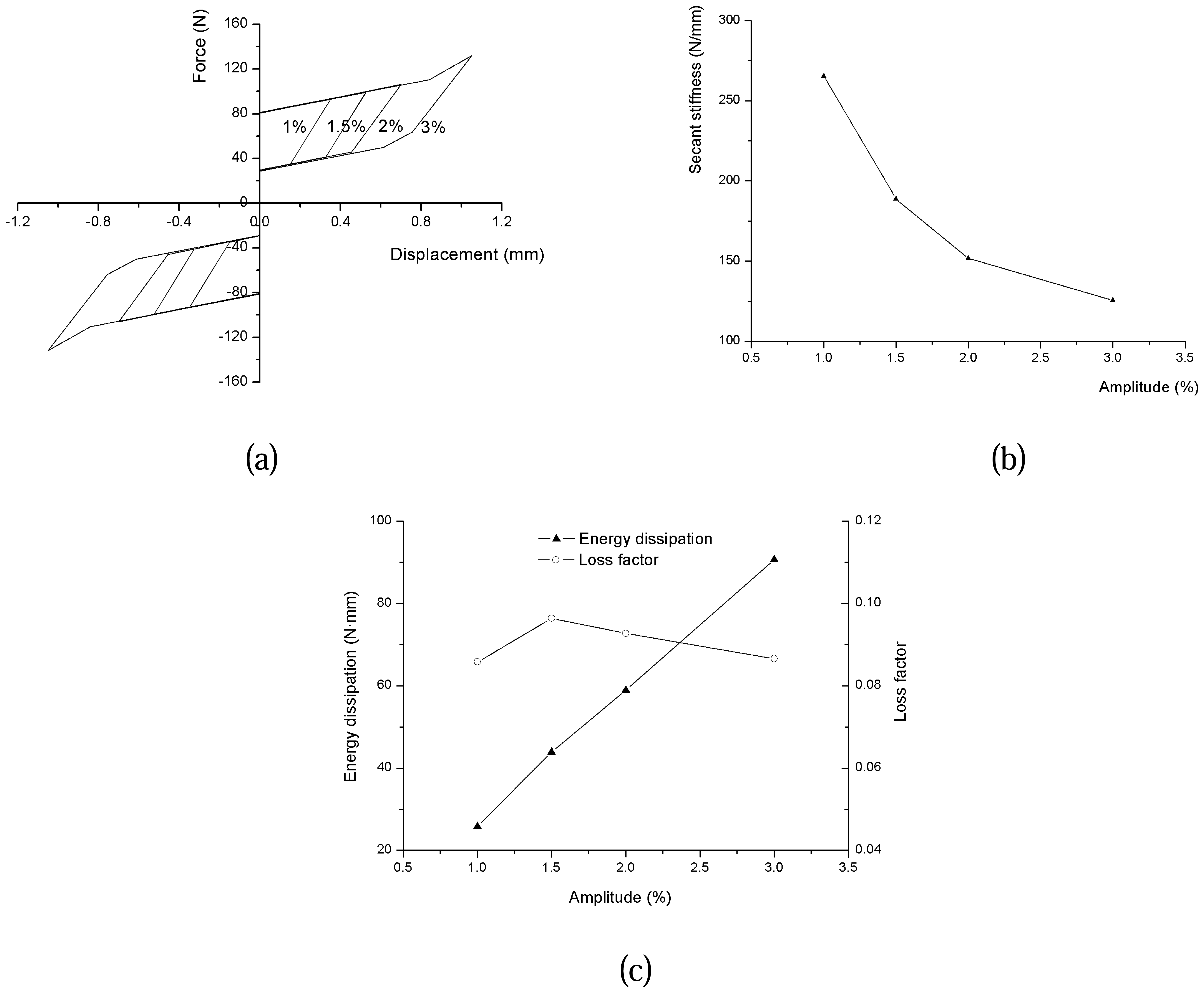
The schematic diagram of the hysteresis loops of SMA damper with different amplitudes, 1, 1.5, 2 and 3%, is shown in figure 14(a). To obtain enough stroke and high damping capacity as well, the NiTi wires are pre-tensioned with 3% strain. The result of figure 14(b) indicates the secant stiffness is significantly influenced by different amplitudes. The dissipated energy is observed to increase linearly associated with increasing amplitude. However, the loss factor of the damper is almost invariable with the variation of amplitudes.
Based on the experimental results shown in figure 8, 9 and 10, the loss factors of the NiTi wire subjected to given conditions can be calculated. From Equation (2), they are found to vary from 0.071 to 0.135. To shed light on this value, the loss factors of some conventional materials are collected in table 1 for a comparison [6]. As can be seen, the loss factor of those materials such as concrete can reach 0.06 only. Rubber, however, exhibits excellent damping property, while it is restricted in many fields by its poor ultimate strength. Furthermore, the loss factors of the SMA based micro-damper change from 0.058 to 0.096, which can be easily observed from figure 12(c), f13(c) and f14(c). Consequently, the conclusion may be drawn that both the SMA materials and the damper own good energy dissipation ability and high tensile strength as well.
Alternatively, the size of the designed SMA damper can be changed for different damping requirements. The maximum force and stroke can be determined by choosing different number and length of NiTi wires. And the mechanical behaviors like critical stress, secant stiffness, energy dissipation and loss factor may vary in accordance with the variation of NiTi wires also.
5. Conclusions
The influence of loading-unloading cycles to the mechanical behavior of NiTi wires is observed prior to other tests, illustrating the cyclic effect on NiTi wires at temperature 294K may be ignored after 100 cycles. Moreover, a series of tension tests for damping behavior of NiTi wires subjected to different temperatures, strain rates and strain amplitudes are conducted. The experimental result shows the energy dissipation of the wires is almost independent of temperature, whereas strongly dependent on strain rate and amplitude in the experimental conditions.
In terms of the experimental results of NiTi wires, a new SMA micro-damper through utilizing NiTi wires are investigated theoretically. The functional principle is introduced in detail and some damping properties involving secant stiffness, energy dissipation and loss factor are estimated and analyzed.
It is found the secant stiffness is slightly changed with different temperatures and strain rates, whereas largely changed with strain amplitudes. The dissipated energy slightly increases with increasing temperature but greatly with strain amplitude. For strain rates up to 0.01s-1 the energy dissipation decreases, while it slightly increases between 0.01s-1 and 0.1s-1. The influences of various temperatures, strain amplitudes and high strain rates on loss factor of the micro-damper are not significant. Nevertheless, the loss factor decreases around 36% when the micro-damper is subjected to low strain rate ranging from 5×10⁻⁴s-1 to 0.01s-1.
Owning good energy dissipation ability, the micro-damper is expected to be used as an actuation means of the micro-gripper, the joint component of robotic and micro-actuators, or energy absorber for suspension system of automobile and structures/machines.
Acknowledgments
This work was supported by Inha University.
References and Notes
- Brinson, L.C.; Lammering, R. Finite element analysis of the behavior of shape memory alloys and their applications. Int. J. Solids Struct. 1993, 30(23), 3261–3280. [Google Scholar]
- Auricchio, F.; Taylor, R.L.; Lubliner, J. Shape-memory alloys: macromodelling and numerical simulations of the superelastic behavior. Comput. Meth. Appl. Mech. Eng. 1997, 146, 281–312. [Google Scholar]
- Humbeeck, J.V.; Kustov, S. Active and passive damping of noise and vibrations through shape memory alloys: applications and mechanisms. Smart Mater. Struct. 2005, 14, S171–S185. [Google Scholar]
- Thomson, P.; Balas, G.J.; Leo, P.H. The use of shape memory alloys for passive structural damping. Smart Mater. Struct. 1995, 4, 36–42. [Google Scholar]
- Wang, R.; Cho, C.; Kim, C.; Pan, Q. A proposed phenomenological model for shape memory alloys. Smart Mater. Struct. 2006, 15, 393–400. [Google Scholar]
- De Silva, C.W. Vibration: Fundamentals and Practice.; CRC Press, 2000. [Google Scholar]
- Pieczyska, E.; Gadaj, S.; Nowacki, W.K.; Hoshio, K.; Makino, Y.; Tobushi, H. Characteristics of energy storage and dissipation in TiNi shape memory alloy. Sci. Technol. Adv. Mater. 2005, 6, 889–894. [Google Scholar]
- Saadat, S.; Salichs, J.; Noori, M.; Hou, Z.; Davoodi, H.; Bar-on, I.; Suzuki, Y.; Masuda, A. An overview of vibration and seismic applications of NiTi shape memory alloy. Smart Mater. Struct. 2002, 11, 218–229. [Google Scholar]
- Humbeeck, J.V. Non-medical applications of shape memory alloys. Mater. Sci. Eng. A 1999, 275, 134–148. [Google Scholar]
- Tamai, H.; Kitagawa, Y. Pseudoelastica behavior of shape memory alloy wire and its application to seismic resistance member for building. Comput. Mater. Sci. 2002, 25, 218–227. [Google Scholar]
- Krulevitch, P.; Lee, A.P.; Ramsey, P.B.; Trevino, J.C.; Hamilton, J.; Northrup, M.A. Thin film shape memory alloy microactuators. J. Microelectromech. Syst. 1996, 5(4), 270–282. [Google Scholar]
- Duerig, T.; Pelton, A.; Stöckel, D. An overview of nitinol medical applications. Mater. Sci. Eng. A 1999, 275, 149–160. [Google Scholar]
- Tabib-Azar, M.; Sutapun, B.; Huff, M. Applications of TiNi thin film shape memory alloys in micro-opto-electro-mechanical systems. Sens. Actuators 1999, 77, 34–38. [Google Scholar]
- Ohta, A.; Bhansali, S.; Kishimoto, I.; Umeda, A. Novel fabrication technique of TiNi shape memory alloy film using separate Ti and Ni targets. Sens. Actuators 2000, 86, 165–170. [Google Scholar]
- Fu, Y.; Huang, W.; Du, H.; Huang, X.; Tan, J.; Gao, X. Characterization of TiNi shape-memory alloy thin films for MEMs applications. Surf. Coat. Technol. 2001, 145, 107–112. [Google Scholar]
- Shoji, S.; Esashi, M. Micorflow devices and systems. J. Micromech. Microeng. 1994, 4, 157–171. [Google Scholar]
- Makino, E.; Mitsuya, T.; Shibata, T. Fabrication of TiNi shape memory micropump. Sens. Actuators A 2001, 88, 256–262. [Google Scholar]
- Kohl, M.; Krevet, B.; Just, E. SMA microgripper system. Sen. Actuators A 2002, 97-98, 646–652. [Google Scholar]
- Zorman, C.A.; Mehregany, M.; Kahn, H.; Heuer, A.H. New developments in MEMS using SiC and TiNi shape memory alloy materials. Curr. Opin. Solid State Mater. Sci. 1997, 2(5), 566–570. [Google Scholar]
- Zhong, Z.W.; Yeong, C.K. Development of a gripper using SMA wire. Sens. Actuators A 2006, 126, 375–381. [Google Scholar]
- Zhong, Z.W.; Chan, S.Y. Investigation of a gripping device actuated by SMA wire, Sens. Actuators A 2007, 136, 335–340. [Google Scholar]
- Dolce, M.; Cardone, D.; Marnetto, R. Implementation and testing of passive control devices based on shape memory alloys. Earthquake Engng. Struct. Dyn. 2000, 29, 945–968. [Google Scholar]
- Wagner, M.; Sawaguchi, T.; Kausträter, G.; Höffken, D.; Eggeler, G. Structural fatigue of pseudoelastic NiTi shape memory wires. Mater. Sci. Eng. A 2004, 378, 105–109. [Google Scholar]
- Yawny, A.; Sade, M.; Eggeler, G. Pseudoelastic cycling of ultra-fine-grained NiTi shape-memory wires. Z. Metallkd. 2005, 96(6), 608–618. [Google Scholar]
- Piedboeuf, M.C.; Gauvin, R. Damping behaviour of shape memory alloys: strain amplitude, frequency and temperature effects. J. Sound Vibr. 1998, 214(5), 885–901. [Google Scholar]
- DesRoches, R.; Asce, M.; McCormick, J.; Delemont, M. Cyclic properties of superelastic shape memory alloy wires and bars. J. Struct. Eng. 2004, 130(1), 38–46. [Google Scholar]
- Dolce, M.; Cardone, D. Mechanical behavior of shape memory alloys for seismic applications 2. Austenite NiTi wires subjected to tension. Int. J. Mech. Sci. 2001, 43, 2657–2677. [Google Scholar]
- Dolce, M.; Cardone, D. Mechanical behavior of shape memory alloys for seismic applications 1. Martensite and austenite NiTi bars subjected to torsion. Int. J. Mech. Sci. 2001, 43, 2631–2656. [Google Scholar]
Figure 1.
Schematic sketch of the pseudoelasticity hysteresis behavior.

Figure 2.
The realization of the damping device: (a) Spring – recentering element; (b) SMA wire – energy dissipation element; (c) Damper – complete functional device.
Figure 2.
The realization of the damping device: (a) Spring – recentering element; (b) SMA wire – energy dissipation element; (c) Damper – complete functional device.

Figure 3.
The prototype of SMA damper.

Figure 4.
The installation of SMA wires.

Figure 5.
The NiTi wire wound around the slipper.

Figure 6.
The configuration of the micro-damper: (a) Before loading; (b) During loading (F > Fc).
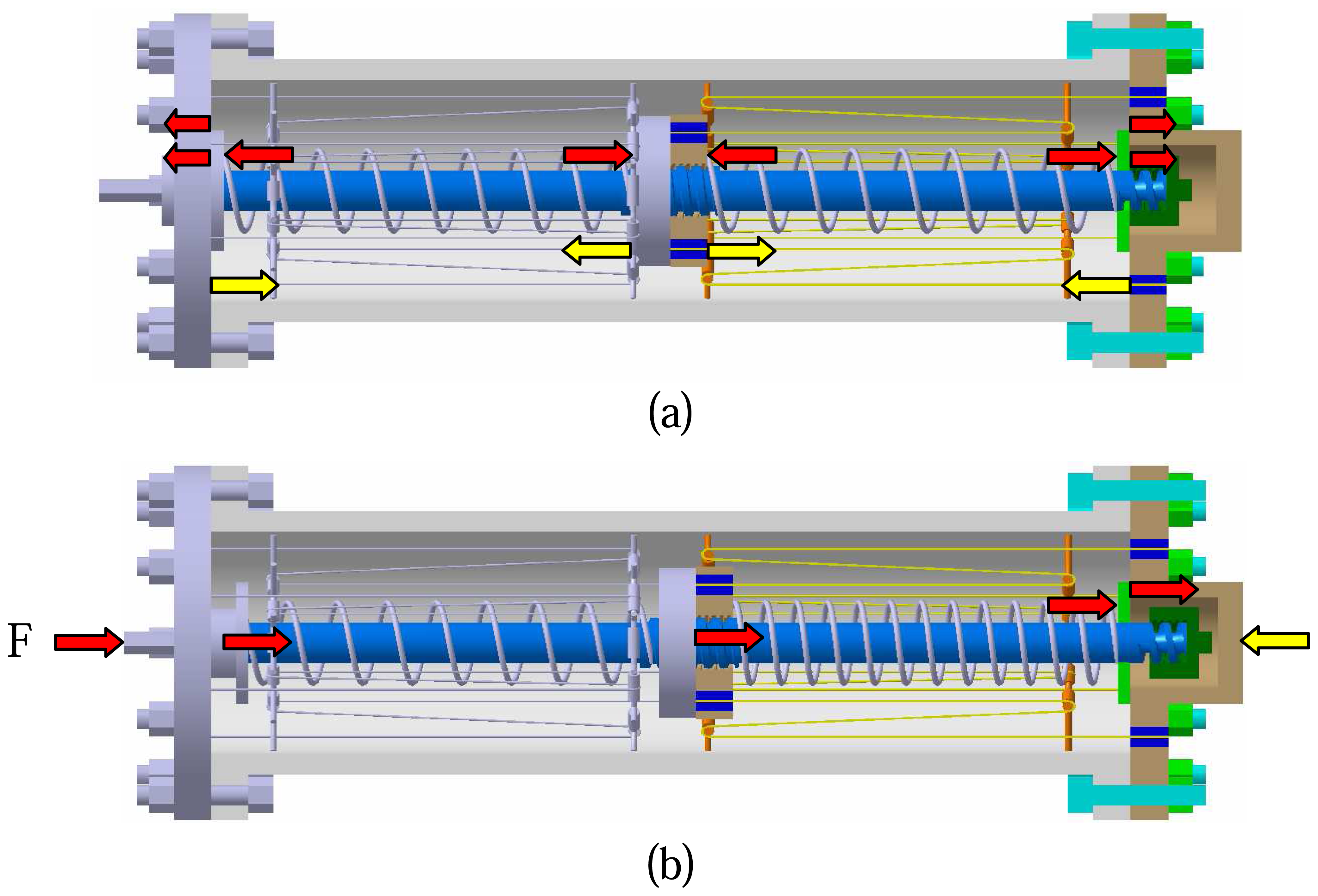
Figure 7.
The schematic illustration for the influence of cyclic effect to NiTi wires.
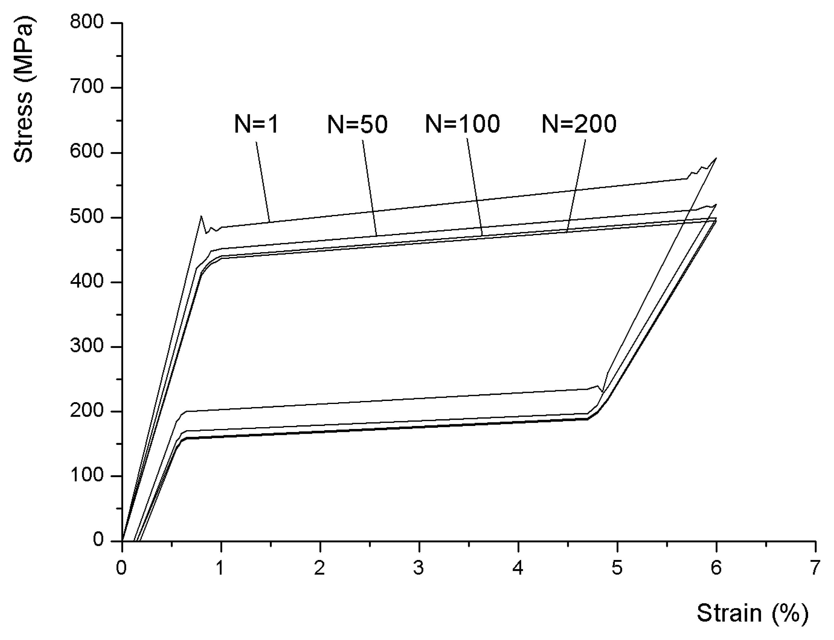
Figure 8.
The influence of various temperatures on NiTi wires.
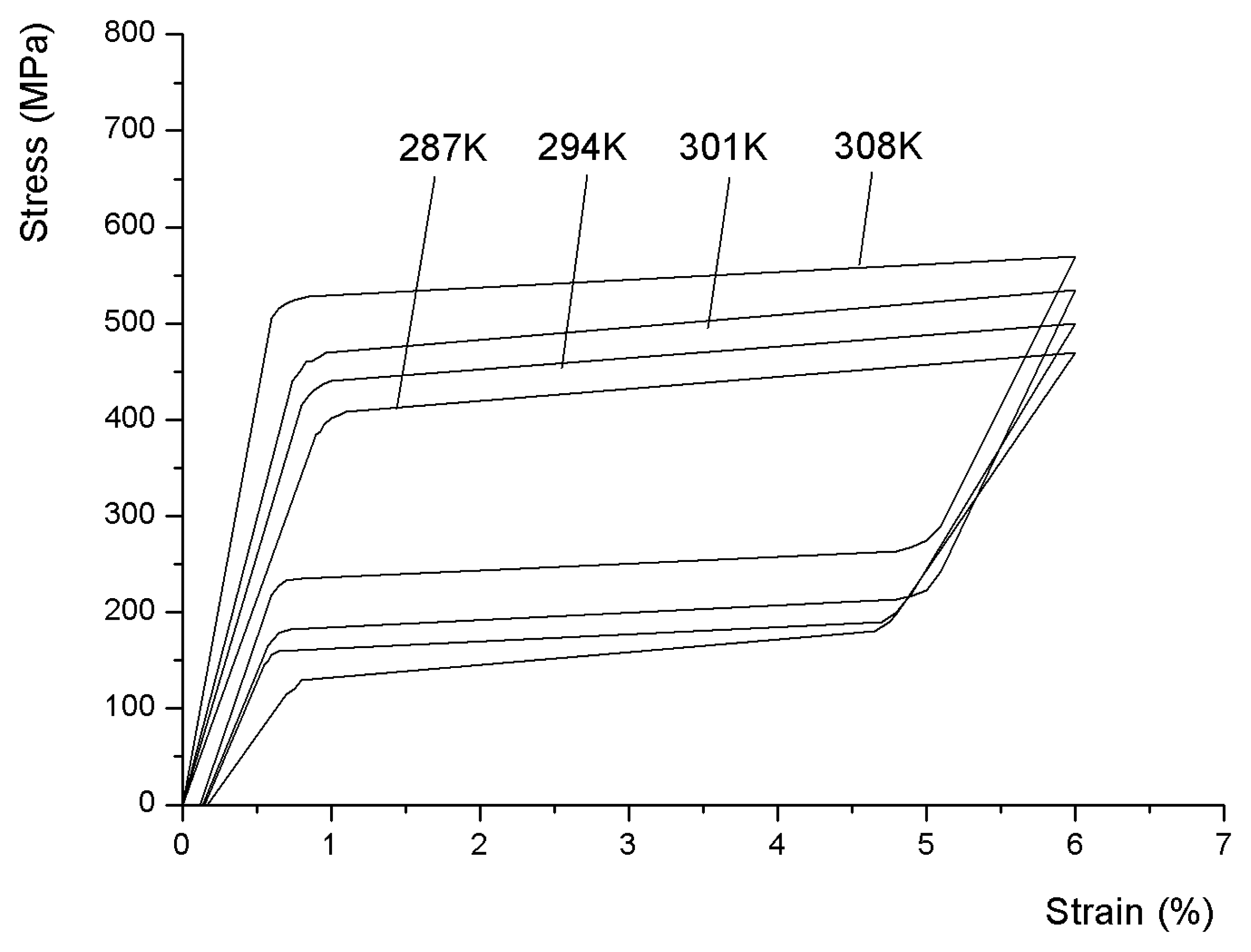
Figure 9.
The influence of various strain rates on NiTi wires.

Figure 10.
The influence of various strain amplitudes on NiTi wires.
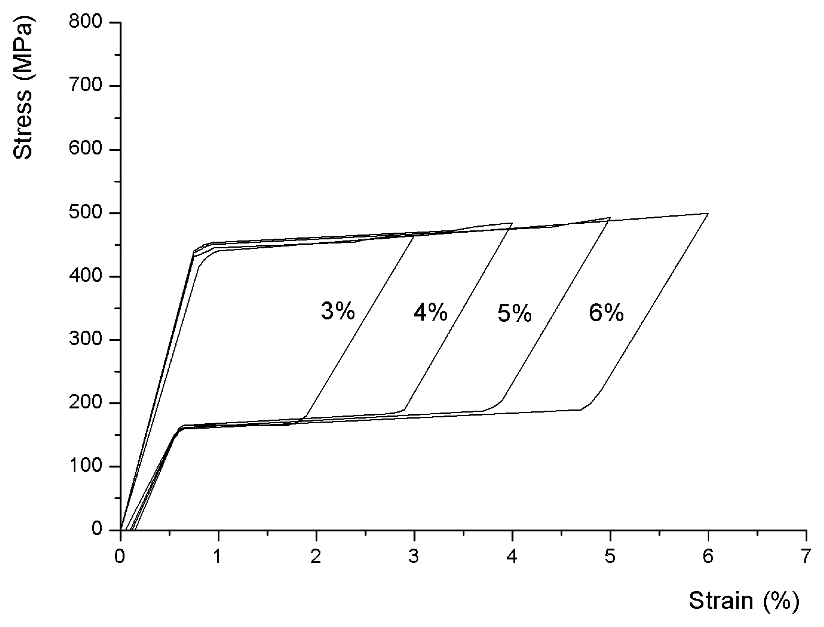
Figure 11.
Schematic diagram of dissipated energy and maximum potential energy.
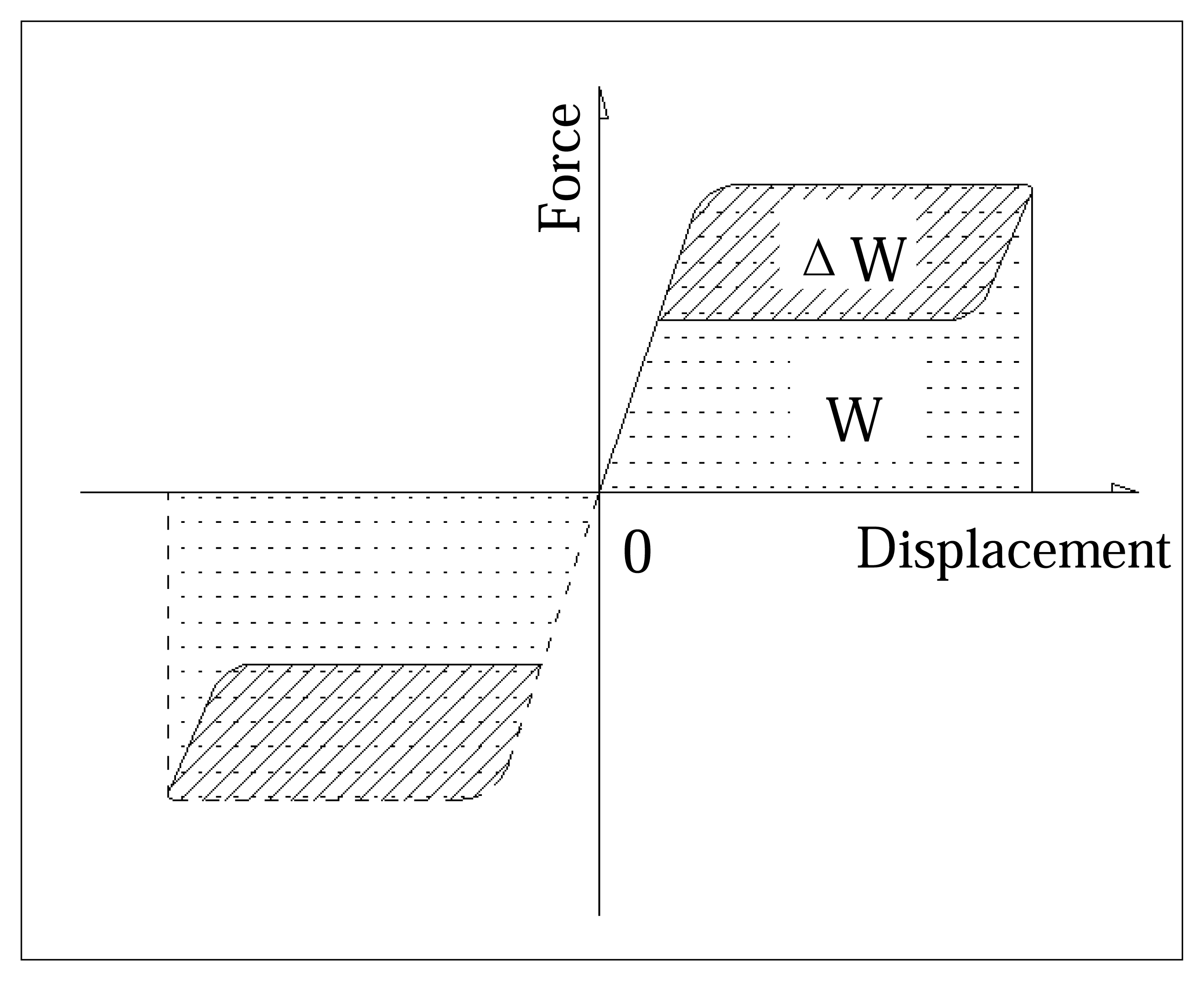
Figure 12.
Mechanical behavior of damper with temperature variation: (a) Schematic diagram of the force-displacement curve; (b) Secant stiffness; (c) Dissipated energy and loss factor.
Figure 12.
Mechanical behavior of damper with temperature variation: (a) Schematic diagram of the force-displacement curve; (b) Secant stiffness; (c) Dissipated energy and loss factor.
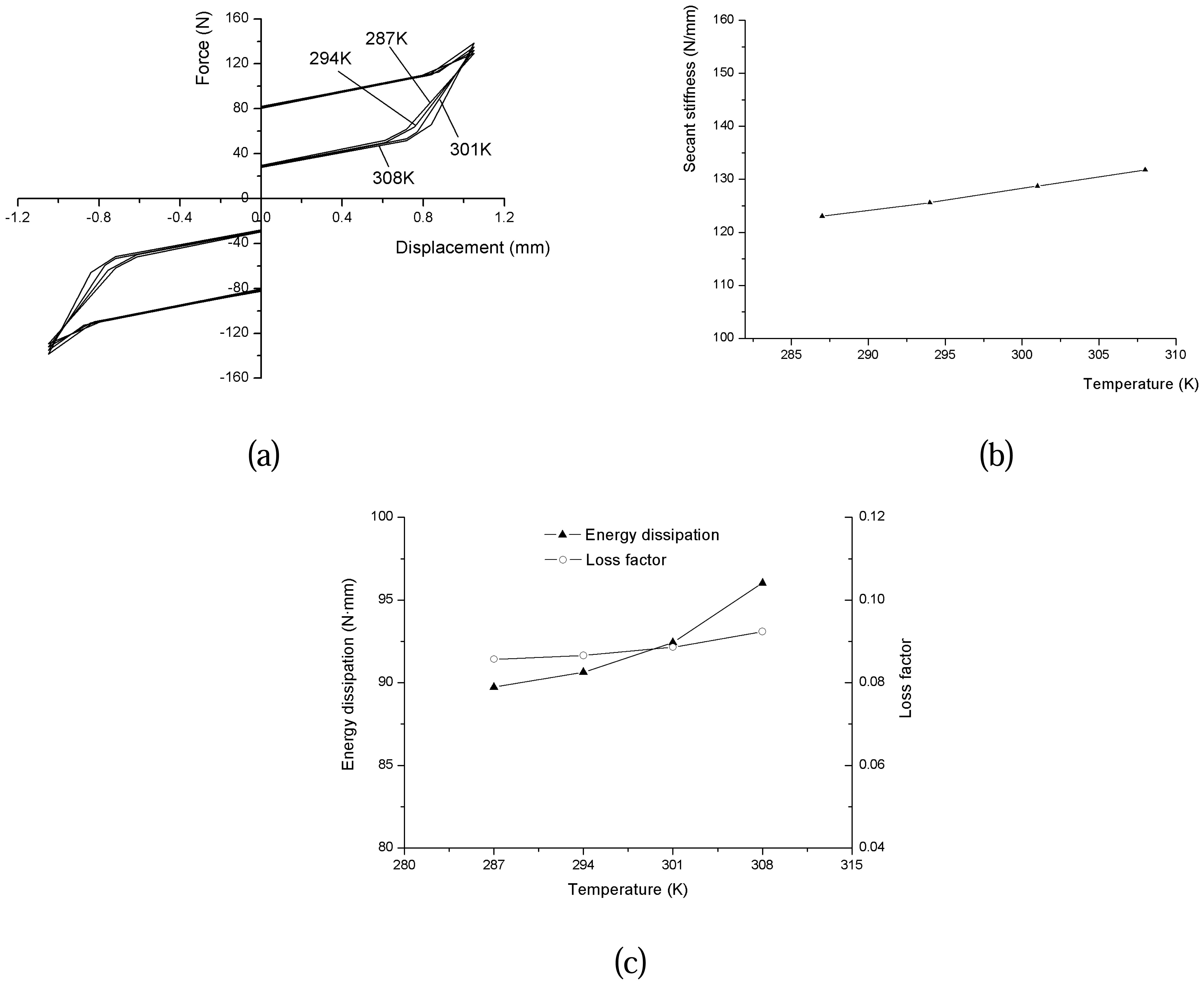
Figure 13.
Mechanical behavior of damper with strain rate variation: (a) Schematic diagram of the force-displacement curve; (b) Secant stiffness; (c) Dissipated energy and loss factor.
Figure 13.
Mechanical behavior of damper with strain rate variation: (a) Schematic diagram of the force-displacement curve; (b) Secant stiffness; (c) Dissipated energy and loss factor.
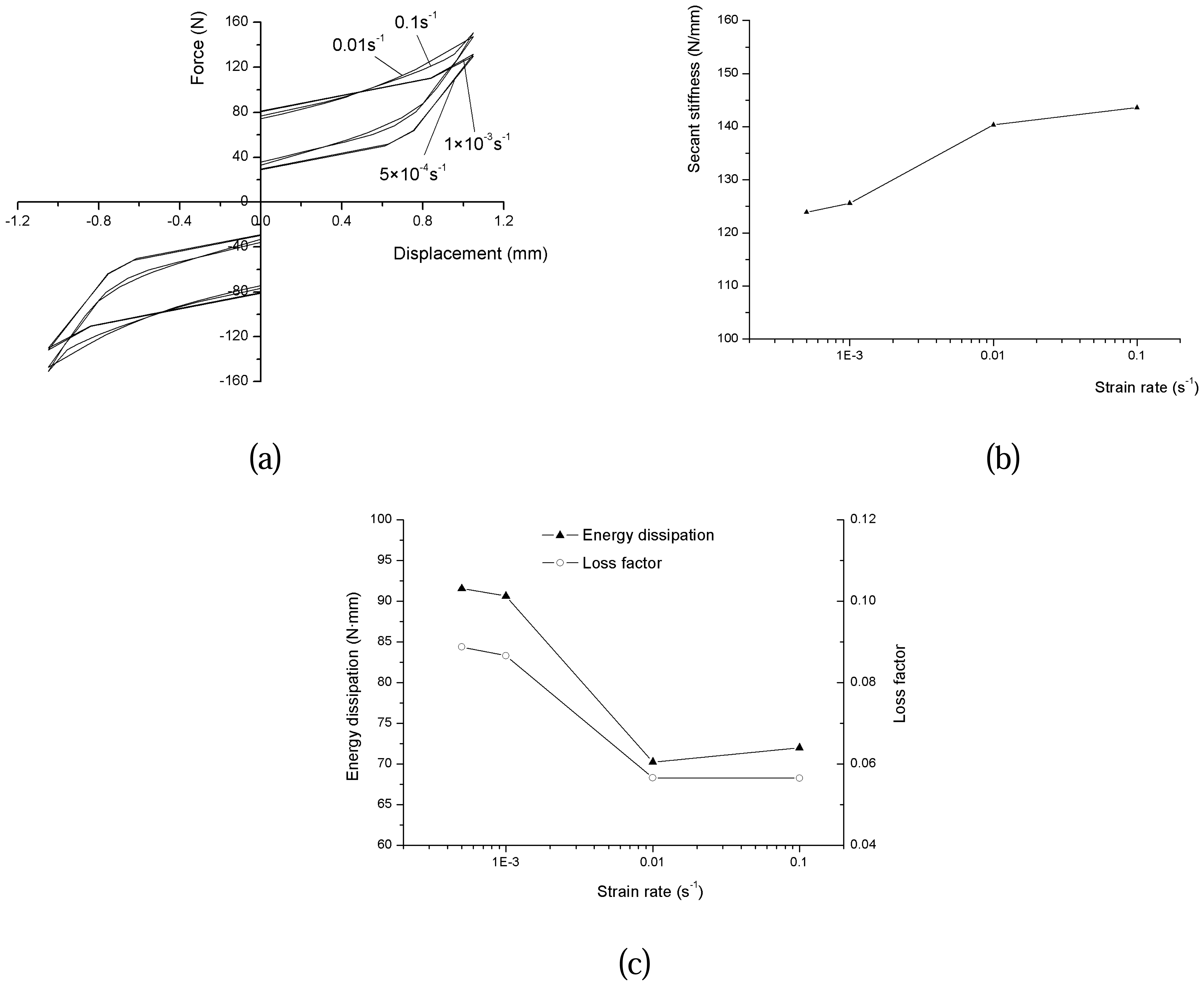
Figure 14.
Mechanical behavior of damper with strain amplitude variation: (a) Schematic diagram of the force-displacement curve; (b) Secant stiffness; (c) Dissipated energy and loss factor.
Figure 14.
Mechanical behavior of damper with strain amplitude variation: (a) Schematic diagram of the force-displacement curve; (b) Secant stiffness; (c) Dissipated energy and loss factor.

| Materials | Loss factor |
|---|---|
| Aluminum | 2×10⁻⁵ to 2×10⁻³ |
| Concrete | 0.02 to 0.06 |
| Glass | 0.001 to 0.002 |
| Rubber | 0.1 to 1.0 |
| Steel | 0.002 to 0.01 |
| Wood | 0.005 to 0.01 |
© 2007 by MDPI ( http://www.mdpi.org). Reproduction is permitted for noncommercial purposes.
Share and Cite
MDPI and ACS Style
Pan, Q.; Cho, C. The Investigation of a Shape Memory Alloy Micro-Damper for MEMS Applications. Sensors 2007, 7, 1887-1900. https://doi.org/10.3390/s7091887
AMA Style
Pan Q, Cho C. The Investigation of a Shape Memory Alloy Micro-Damper for MEMS Applications. Sensors. 2007; 7(9):1887-1900. https://doi.org/10.3390/s7091887
Chicago/Turabian StylePan, Qiang, and Chongdu Cho. 2007. "The Investigation of a Shape Memory Alloy Micro-Damper for MEMS Applications" Sensors 7, no. 9: 1887-1900. https://doi.org/10.3390/s7091887