Seven Operation Modes and Simulation Models of Solar Heating System with PCM Storage Tank

1
School of Mechanical Engineering, Southwest Jiaotong University, Chengdu 610031, China
2
School of Urban Construction & Environment Engineering, Chongqing University, Chongqing 400045, China
*
Author to whom correspondence should be addressed.
Energies 2017, 10(12), 2128; https://doi.org/10.3390/en10122128
Submission received: 15 November 2017
/
Revised: 6 December 2017
/
Accepted: 11 December 2017
/
Published: 14 December 2017
(This article belongs to the Special Issue Solar Technologies for Buildings)
Abstract
:A physical model and dynamic simulation models of a solar phase-change heat storage heating system with a plate solar collector, phase-change material (PCM) storage tank, plate heat exchanger, and auxiliary heat sources were established. A control strategy and numerical models for each of seven different operation modes that cover the entire heating season of the system were developed for the first time. The seven proposed operation modes are Mode 1: free cooling; Mode 2: reservation of heat absorbed by the solar collector in the PCM storage tank when there is no heating demand; Mode 3: direct supply of the heating demand by the solar collector; Mode 4: use of the heat absorbed by the solar collector to meet the heating demands, with the excess heat stored in the PCM storage tank; Mode 5: use of heat stored in the PCM storage tank to meet the heating demands, Mode 6: combined use of heat stored in the PCM storage tank and the auxiliary heating sources to meet the heating demands; and Mode 7: exclusive use of the auxiliary heat sources in order to meet the heating demands. Mathematical models were established for each of the above seven operation modes, taking into consideration the effects of the outdoor meteorological parameters and terminal load on the heating system. The real-time parameters for the entire heating season of the system with respect to the different operation modes can be obtained by solving the simulation models, and used as reference for the optimal design and operation of the actual system.
1. Introduction
Solar energy is a clean, renewable, and safe energy, and is thus very relevant in the modern society, amidst issues of energy shortage and environmental pollution. However, solar energy has the drawbacks of intermittence and a low energy density. This necessitates the use of a thermal storage unit to save the energy at times of excess supply, to make up for shortfalls at times of mismatch between solar radiation and energy demands, such as from a solar heating system. However, the traditional heat storage water tank has some problems, which include bulkiness and severe heat loss, owing to the heat being stored in the form of sensible heat. Moreover, the system performance is unstable, due to the large range of temperature change [1]. The adoption of latent heat storage (LHS) using a phase-change material (PCM) has been suggested as a perfect solution to this problem. A PCM is characterized by a high latent heat density and isothermal phase change, but the heat performance should be enhanced [2,3,4,5]. The modified PCMs use in a heat storage unit would not only reduce the required volume, but also enable the storage and release of heat at a nearly constant temperature, thus overcoming the shortcomings of traditional heat storage water tank [6].
Extensive work has been carried out to explore the application of PCMs in solar thermal energy [7], such as solar power plants [8], solar air heaters [9], solar water heaters [10,11,12], solar desalination facilities, solar cookers, solar air conditioning [13,14], and so on. PCMs for heat storage units have been investigated by many scholars [15,16,17]. Mehling et al. [18] proposed the addition of a PCM module to the top of a heat storage water tank to increase the storage density of the system and compensate for the heat loss from the top layer. The experiments and simulation were performed using different cylindrical PCM modules, with only 1/16 of the volume of the storage consisting of the PCM. By this means, 3/16 of the water at the top of the store was held warm for 50–200% longer, with the average energy density increased by 20–45%. Furthermore, the abovementioned 3/16 part of the water was reheated by heat from the module within 20 min after being cooled. Nallusamy et al. [19] experimentally evaluated the thermal performance of a packed-bed latent-heat thermal energy storage (TES) unit integrated with a flat-plate solar collector. The PCM of the TES unit consisted of spherical paraffin capsules packed into an insulated cylindrical storage tank. The heat transfer fluid (HTF) mass flow rate was confirmed to significantly affect the heat extraction rate from the solar collector and TES tank. The packed-bed LHS system also reduced the size of the storage tank appreciably, and its batchwise discharge of hot water from the TES tank is most suitable for applications with intermittent energy demands. Talmatsky et al. [20] constructed models of heat storage tanks with and without a PCM, and with other parts including a collector, pump, controller, and auxiliary heater. The results for all the scenarios that the model was used to simulate indicated that, contrary to expectations, the use of a PCM in the storage tank did not afford any significant benefit with respect to the energy supplied to the end-user. This was mainly because of the undesirable effect of increased heat loss during the nighttime, due to reheating of the water by the PCM. Padovan et al. [21] optimized a PCM-improved storage tank using mono- and multi-objective genetic algorithms. The optimization was performed using the mode FRONTIER optimization tool, while the system was analyzed using a modified version of the building energy simulation code ESP-r. Najafian et al. [22] reported the outcomes of adding a PCM to a standard domestic hot water tank, with respect to the energy consumption and the discharge period, and suggested a method for optimizing the tank based of the discharge time. Navarro et al. [23] investigated the incorporation of high-density polyethylene spheres as PCM in domestic hot water tanks. Laboratory analysis indicated that it was necessary to thermally cycle and clean the polyethylene spheres before their application to a real domestic hot water tank, in order to stabilize their PCM content.
At present, the evaluation of the dynamic performance of a solar heating system with PCM is mainly by experiment [24]. However, the performance of a combined solar-heat pump system with an energy storage incorporating a PCM package for residential heating was investigated both experimentally and theoretically by Kaygusuz et al. [25] at the Karadeniz Technical University. It was concluded that the dual-source heat pump system exploits the benefits of the best features of both the series and parallel systems. Al-Hinti et al. [26] experimentally investigated the performance of a water-PCM storage for use in conventional solar water heating systems. Over a test period of 24 h, the stored water temperature was observed to be at least 30 °C higher than the ambient temperature. Zhang et al. [27] proposed a new solar energy-phase change storage-floor radiant heating system for achieving a comfortable indoor environment during winter, and implemented it in an office building in Urumqi, China. They reported a 30% increase in solar energy utilization compared with a traditional solar heating system. Mazman et al. [28] conducted tests on a complete solar heating system constructed at the University of Lleida, Spain, under real operating conditions. New graphite compounds with optimized thermal properties were respectively used as the PCM, namely, 80:20 weight percent mixtures of paraffin and stearic acid (PS), paraffin and palmitic acid (PP), and stearic acid and myristic acid (SM). PS was determined to afford the best thermal performance enhancement of the solar domestic hot water (SDHW) tank (74% efficiency). Prieto et al. [29] examined the energy performance of a heating-power micro-cogeneration system used to heat a 450 m2 office space. A hot water thermal energy storage system and two latent-heat TES systems with PCM plate heat exchangers were considered, and their performances under dynamic conditions were analyzed and compared. The use of palmitic acid as the PCM was found to produce better results, namely, a higher heat transfer rate, greater accumulated energy, and a lower number of storage units required to meet the heating demand. Kanimozhi et al. [30] used models and experiments to analyze the performance of a TES system, and developed a method for enhancing the heat transfer using honey and paraffin wax. The performance was experimentally appraised for both the charging and discharging of the PCM.
The energy efficiency of a solar heating system with a PCM storage tank should be synthetically considered over the entire heating cycle. Most previous studies considered only a few days or hours, and only particular operating conditions in their experimental investigations, and there is no relevant study that employed numerical simulation or experiments to evaluate the performance of the entire system over an extended period.
In this work, a dynamic simulation model of a solar heating system with a hybrid heat source composed of flat-plate solar collectors, a water tank with a plate phase-change heat storage unit, a plate heat exchanger, and auxiliary heat sources, in consideration of the entire heating cycle and operation in different heating mode, was firstly established. Furthermore, a control strategy and numerical models for each of seven different operation modes that cover the entire heating season of the system were developed for the first time.
On the basis of above work, the mathematical models were established for each of the above seven operation modes, and each of the modes was automatically simulated by setting the control parameters according to the control strategy, taking into consideration the effects of the outdoor meteorological parameters and terminal load on the heating system. The real-time parameters for the entire heating season of the system with respect to the different operation modes can be obtained by solving the simulation models, and used as reference for the optimal design and operation of the actual system.
2. Structure, Operation Mode, and Control Strategy of SHS-PCM
2.1. Structure
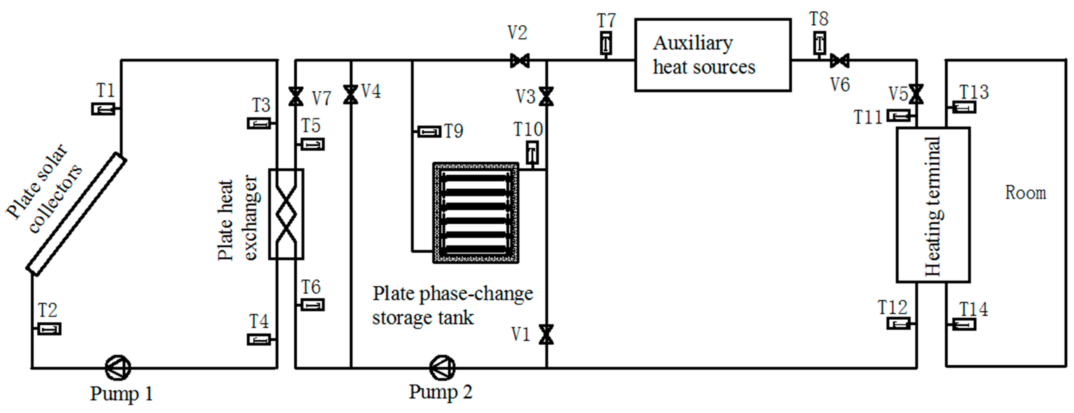
Figure 1 shows the typical Solar heating system with PCM storage tank (SHS-PCM) that was investigated in this study. The system is mainly composed of a solar collection system (SCS), phase change thermal storage system (PCTSS), and indoor heating system (IHS). The solar collection system, which is the main thermal source, includes flat-plate solar collectors, a plate heat exchanger, pump 1, valves, and pipelines. The PCTSS, which is the heat supply source, included a PCM storage tank, auxiliary heat sources, a plate heat exchanger, pump 2, valves, and pipelines. The software of DeST was used to calculate the hourly heating load of the indoor heating system, to set a suitable supply water temperature and backwater temperature for the indoor heat exchanger.
2.2. Operation Modes and Control Strategy
2.2.1. Operation Modes
The following seven heating operation modes are proposed for the SHS-PCM:
Mode 1: Free cooling.
Mode 2: Reservation of the heat absorbed by the solar collection system in the PCM storage tank when no indoor heating is required.
Mode 3: Direct supply of the indoor heating demand by the solar collection system.
Mode 4: Supply of heat absorbed by the solar collection system to the rooms, with the excess absorbed heat stored in the PCM storage tank.
Mode 5: Supply of the heat from the PCM storage tank to the rooms.
Mode 6: Joint supply of the room heating demand by the PCM storage tank and auxiliary heat sources.
Mode 7: Supply of the room heating demand by the auxiliary heat sources alone.
The flat-plate solar collector collects solar radiation and uses it to heat the contained water. When the water reaches the phase-transition temperature of the PCM, the PCM storage tank begins to store the heat absorbed by the water (Mode 2). If the water is heated to the indoor heat supply temperature, the heat can be directly supplied to the rooms (Mode 3). If excess heat is available beyond that demanded by the rooms, it can be stored in the PCM storage tank (Mode 4). If there is no useful solar radiation to collect, the solar collection system would be temporarily out of service, and the room heating demands would first be supplied by the PCM storage tank (Mode 5). If, however, the PCM storage tank contains insufficient thermal energy to meet the heating demands of the room, it would be assisted by the auxiliary heat sources (Mode 6). If the PCTSS and SCS are both incapable of contributing to the indoor heating requirements, the auxiliary heat sources would operate alone (Mode 7).
2.2.2. Control Strategy
As noted earlier, the SHS-PCM is mainly composed of the SCS, PCTSS, and IHS. Control strategies for such systems usually consider the heating sources (SCS and PCTSS), while the IHS is ignored. The following control strategies are proposed:
(1) Control strategy for SCS
The control parameter is the heating side outlet temperature (Th2,o) of the plate heat exchanger, and the controlled object is pump 1, which operates when Th2,o > Tm (phase change temperature of PCM). Te,o means the heating terminal outlet temperature, and Te,in means the inlet temperature, so ∆t is the temperature difference of Te,in and Te,o. If Tm < Th2,o < Te,o + ∆t, the heat could be stored in the PCM storage tank; and if Th2,o > Te,o + ∆t, the heat could be directly supplied to the rooms, with the excess energy stored in the PCM storage tank.
(2) Control strategy for PCTSS
Pump 2 is operated when the building requires heating. The control parameter is the outlet temperature (Tf,o) of the PCM storage tank, and the controlled objects are the auxiliary heat sources and the PCM storage tank. If Tf,o > Te,o + ∆t, the heat stored in the PCM storage tank would be supplied to the building; and if Te,o < Tf,o < Te,o + ∆t, the heating requirements would be jointly supplied by the PCM storage tank and auxiliary heat sources. In addition, if Tf,o < Te,o, the heating backwater would be directly transported to the auxiliary heat sources for heating without using the PCM storage tank.
The appropriate control strategy is set up based on the system control model and the relevant measured parameters, as shown in Figure 2.
3. Establishment of Dynamic Simulation Model of System
The dynamic simulation model of the system can be simplified into the four sub-models shown in Figure 3, based on the physical model of the SHS-PCM. The dynamic simulation model of the system can be established by solving the problem based on the physical meaning of each sub-model, the equation of the heat transfer process, and the operation control strategy of the system.
3.1. Theoretical Model of Plate Solar Collector
The heat collection process includes heat transfer between the glass cover plate and the environment, between the glass cover plate and the heat absorption plate, between the heat absorption plate and the bottom plate, and between the heat absorption plate and the side panels. The corresponding heat transfer coefficient can be calculated by analyzing each heat transfer process. Therefore, the heat efficiency, the efficiency factor, and the heat transfer factor of the collector can be obtained using the energy conservation equation. A schematic illustration of the energy conservation of a flat-plate solar collector is shown in Figure 4.
According to the law of energy conservation, the solar radiation energy per unit time projected to the glass cover is equal to the sum of the light loss QC,l, heat loss QC,r, internal energy increment of the collector QC,n, and useful energy QC,us obtained by the working substance, as expressed by Equation (1).
As illustrated in Figure 4, and according to energy conservation, the heat transfer process of the collector includes the following:
- (1)
- Radiation and convection heat transfers between the glass cover and the sky.
- (2)
- Radiation and convection heat transfers between the side and bottom plates of the collector and the environment.
- (3)
- Conduction heat transfer between the outer and inner surfaces of the glass cover plate.
- (4)
- Radiation and convection heat transfers between the absorber plate and the inner surface of the cover plate.
- (5)
- Radiation and convection heat transfers between the heat sink and the inner surface of the insulation shell.
- (6)
- Conduction heat transfer between the inner and outer surfaces of the insulation shell.
- (7)
- Radiation heat transfer between the heat absorbing plate and the side of the thermal insulation shell. Considering the smallness of the angle coefficient of the heat absorption plate and the side plate, it is ignored.
Based on the heat transfer process comprising the above, the network chart of the heat transfer resistance of the flat-plate solar collector is as indicated in Figure 5.
Here, τ in Figure 5 represents the solar radiation transmission rate of the glass cover plate, and represents the absorption rate of heat absorption plate. The subscripts “cond”, “conv,” and “I” represent conduction heat transfer, convection heat transfer, and radiation heat transfer, respectively, while “d-b2” represents the two surfaces involved in the heat exchange.
Each heat transfer process is analyzed to determine the heat transfer coefficient. The equation of the thermal efficiency of the heat collector is obtained from the energy conservation equation. The thermal efficiency of the flat-plate solar collector is the ratio between the useful energy obtained from the collector to the solar radiation incident on the collector surface, as given by the following equation:
where is the instantaneous thermal efficiency of the flat-plate solar collector.
It is assumed that the heat loss coefficient of the collector does not vary with temperature, and the instantaneous efficiency is thus, only a function of the inlet temperature, ambient temperature, and solar radiation intensity, for a given fluid mass flow rate [31]. The instantaneous thermal efficiency of the collector can also be expressed as
The value of a in Equation (3) is determined by the physical properties and structural parameters of the collector, such as the physical properties of the cover and absorber plates, the pipe diameter, spacing of the flow tubes; while b depends on the structural parameters and insulation performance. A plate collector “FKS-1S” is chosen in the present study. According to FKS-1S Flat Plate collector technical specifications, a = 0.85 and b = 3.67 were calculated by the theoretical model of plate solar collector.
3.2. Theoretical Model of PCM Storage Tank
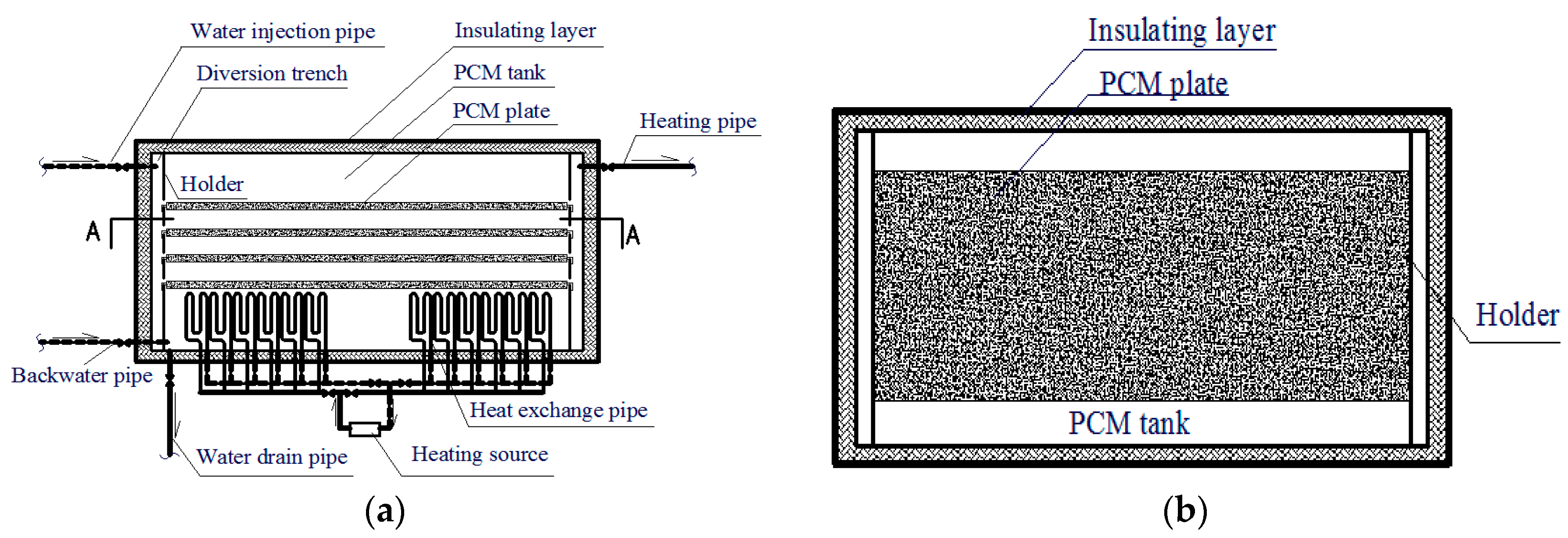
Figure 6 shows a schematic of the PCM storage tank used to develop the simulation model. The PCM is packed into flat metal boxes, which are stacked in layers in the phase-change heat storage unit.
During the transfer of heat between the fluid and the phase-change heat storage unit at any given time, the lower part of the PCM is solidified/melted by the release/absorption of latent heat by the PCM. The lower solid/liquid phase region and the upper liquid/solid phase region are formed next to the boundary of the phase transition interface. The half-layer PCM plate and fluid channel were used to investigate the heat transfer of the PCM storage tank. As indicated in Figure 7, the upper and lower boundaries of the PCM units can be considered as adiabatic surfaces. This is because of the symmetry of the model of the flat phase-change thermal storage unit.
As can be deduced from Figure 7, different types of heat transfer occur in each part of the model. They are as follows: (1) Forced convective heat transfer between the fluid and the plate wall when the fluid flows, and conduction heat transfer between the two when the fluid is static; (2) Conduction heat transfer between solid PCM and the plate wall; (3) Heat storage in the PCM; (4) Internal conduction heat transfer of the PCM.
① Energy conservation equation
The following equations apply:
In Equation (4), Am is the cross-sectional area of the transformed PCM, Kf-m is the heat transfer coefficient, p is the wetted perimeter, Tf is the fluid temperature, and Tm is the phase transition temperature of the PCM.
In Equation (7), Rf, Rp, and Rm are the convective thermal resistance of the fluid, conductive thermal resistance of the package plate wall, and conductive thermal resistance of the transformed PCM, respectively.
- , , .
- Initial condition: , ,
- Boundary condition: .
② Nondimensionalization
Dimensionless parameters were introduced into the dimensionless variables to enable more extensive and intensive analysis of the heat transfer characteristics of the phase change heat storage unit:
, , , , , , and , where , , , and .
The following dimensionless equations were obtained for phase-change thermal storage unit:
- Initial condition:
- Boundary condition:
3.3. Theoretical Model of Plate Heat Exchanger
The plate heat exchanger is a heat exchange component between the solar collector system and the PCM storage tank. The relationship between the inlet and outlet parameters of the plate heat exchanger is determined by the principle of heat balance with no heat loss.
where Qh is the heat quantity of the plate heat exchanger (W), Kh is the heat transfer coefficient (W/(m2·°C)), Ah is the area of the plate heat exchanger (m2), and ΔTht is the logarithmic mean temperature difference between both sides of the heat exchanger (°C), given by .
3.4. Dynamic Simulation Model of SHS-PCM
The mathematical heat transfer model of the plate solar collectors, PCM storage tank, and plate heat exchanger has been presented above. In the present study, the load on the heating terminal was calculated using DeST, while the dynamic coupled heat transfer model of the system was developed from the heat transfer equations of the models of the different parts.
The coupling model of the SHS-PCM can be established with respect to the operation modes. For this purpose, the following reasonable assumptions are made for simplicity of the model:
- (a)
- The heat losses in the pump, pipeline, and pipeline valves of the system are negligible.
- (b)
- The internal water temperature is consistent and without stratification, and the PCM is maintained at the phase transition temperature when the PCM storage tank is not operating.
- (c)
- The heat transfer coefficient of the heat exchanger is constant.
The mathematical models were established for each of the seven different operation modes proposed in this paper, and each of the modes was automatically simulated by setting the control parameters defined in Figure 2.
3.4.1. Mathematical Model for Mode 1
This operation mode mainly applies under incident radiation without the application of a terminal load, with all the components being naturally cooled. However, two previous studies [20,31] have suggested that the benefits of the mode are not guaranteed because the gains that accrue during the day through the storage of solar energy by the PCM are counterbalanced by the losses from the storage tank during the night.
For accurate application of the model, the heat dissipation loss of the heat storage tank in the natural cooling stage should be calculated. Because the temperature difference between the interior of the heat storage tank and the environment is large, the loss of heat from the tank would affect its initial temperature and ability to meet the heating requirements when the heating system is switched on the following day.
The heat transfer loss between the water tank and the environment during the operation of the PCM storage tank is neglected to simplify the calculation using the model. At night, the phase-change heat storage tank undergoes natural cooling. If the PCM has been able to store latent heat, i.e., q > 0, it would be assumed that the inner surface temperature of the heat storage tank is equal to the water temperature inside the tank and the phase-transition temperature. The sensible heat of the PCM is neglected while its latent heat is being released. It is assumed that the inner surface temperature of the heat storage tank is equal to the water temperature, and that the heat loss of the water tank is equal to the heat dissipation from the water in the tank. The heat loss per storage tank area, qloss, and the heat dissipation from the water in the tank during time step “tt” are calculated using the temperature of the inside surface of the tank and the ambient air temperature as the boundary conditions. The equations of the system are, thus, as follows:
3.4.2. Dynamic Simulation Model for Mode 2
This operation mode shown in Figure 8 mainly applies under incident radiation, without the application of a terminal load. The thermal storage of the PCM storage tank is regenerated by the SCS, and the heat transfer between the two systems is accomplished through the plate heat exchanger. The useful energy of the solar collector can be determined by Equation (12) or (13) based on the heat efficiency relationship of the flat collector (2).
Ignoring the heat loss from the pipeline, and setting TC,o,i = Th1,in,i, TC,in,i = Th1,o,i, Th2,o,i = Thp,in,i, Th2,in,i = Thp,o,i, and mh = mhp, the heat storage capacity of the PCM storage tank is equal to that of the plate heat exchanger, and the heat transfer capacity of the heat exchanger is equal to that of the plate heat exchanger.
The inlet water temperature of the PCM storage tank at a given time and the outlet temperature at the subsequent time can be determined using the model of the PCM storage tank established in Section 3.2.
The mathematical model for the Mode 2 operation is represented by the simultaneous Equations (10) and (12)–(15).
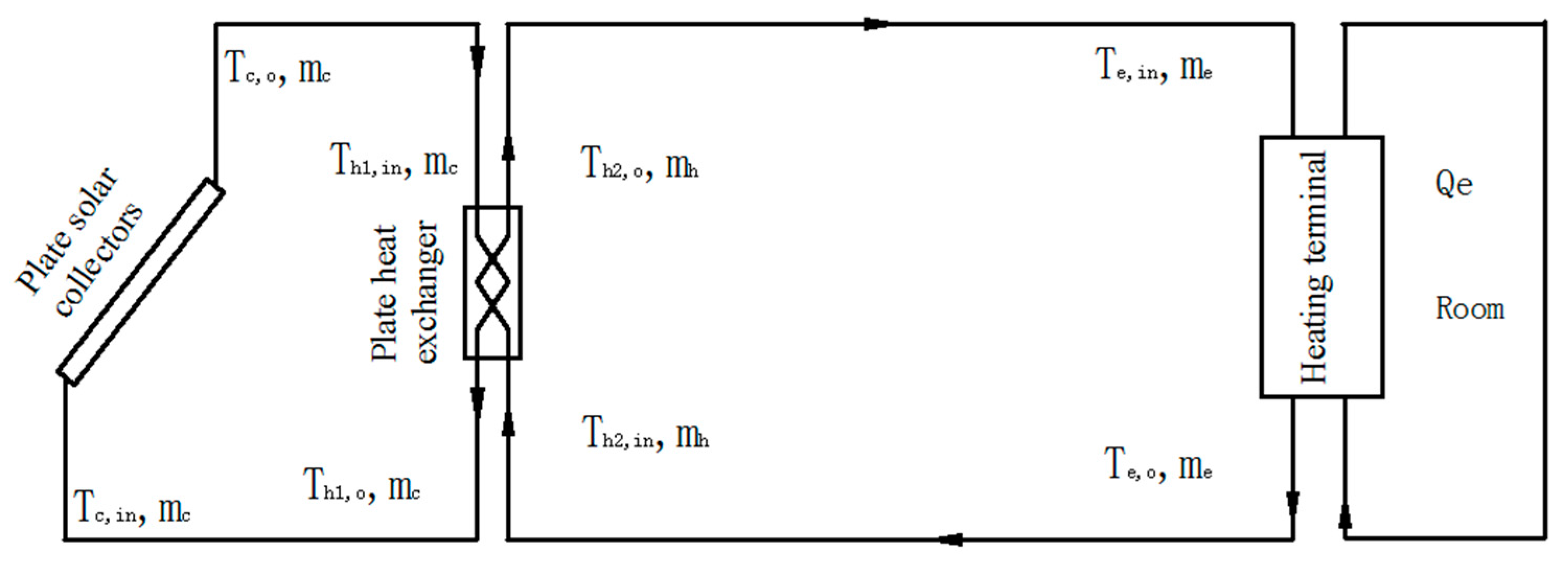
3.4.3. Mathematical Model for Mode 3
This operation mode shown in Figure 9 mainly applies when the solar collector water temperature is sufficient to meet the terminal heating requirements. The energy is transported to the heating terminal of the room by the plate heat exchanger. Ignoring the heat loss from the pipeline, and setting TC,o,i = Th1,in,i, TC,in,i = Th1,o,i, Th2,o,i = Te,in,i, Th2,in,i = Te,o,i, and mh = me, the heat exchange between the heating terminal and the plate heat exchanger is equal to the room load Qe:
The mathematical model for the Mode 3 operation is represented by the simultaneous Equations (10), (12), (13), and (16).
3.4.4. Mathematical Model for Mode 4
This operation mode shown in Figure 10 applies under intense solar radiation, with the heat obtained by the solar collector system supplied to the plate heat exchanger and the heating terminal, and the remainder stored in the PCM storage tank. Ignoring the pipeline and fluid heat losses, and setting TC,o,i = Th1,in,i, TC,in,i = Th1,o,i, Th2,o,i = Thp,in,i = Te,in,i, and mh = me + mhp, the heat obtained on the right side of the plate heat exchanger is equal to the sum of the heat supplied to the terminal and the heat stored in the PCM storage tank (Equation 17), and the terminal heat supply is also equal to the room load (Equation 18). Equation 19 can be obtained by the heat balance principle for node 1.
The mathematical model for the Mode 4 operation is represented by the simultaneous Equations (10), (12), (13), (15), and (17)–(19).
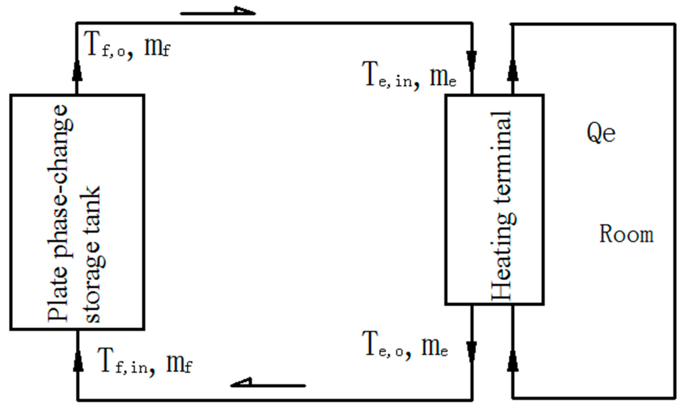
3.4.5. Mathematical Model for Mode 5
This operation mode shown in Figure 11 mainly applies when there is shortage of solar radiation, and the heat stored in the PCM storage tank is used to meet the terminal heating demand. Ignoring the pipeline and fluid heat losses, and setting Tf,o,i = Te,in,i, Tf,in,i = Te,o,i, Tc,o,i+1 = Tc,in,i+1, and mf = me, the heat supplied by the PCM storage tank and the heat transferred by the heating terminal are both equal to the room load Qe.:
The mathematical model for this Mode 5 operation is represented by the simultaneous Equations (12), (13), (15), and (20).
3.4.6. Mathematical Model for Mode 6
This operation mode shown in Figure 12 mainly applies when there is shortage of solar radiation and the heat stored in the PCM storage tank is insufficient to meet the terminal heating demand. The auxiliary heat source is, thus, serially connected, and used to heat the water. Ignoring the pipeline and fluid heat losses, and setting Tf,o,i = Ts,in,i, Ts,o,i = Te,in,i, Tf,in,i = Te,o,i, and mf = ms = me, the combined heat supply from the PCM storage tank and auxiliary heat sources is equal to the heat transferred by the heat exchanger, which is also equal to the room heat load Qe:
The mathematical model for this Mode 6 operation is represented by the simultaneous Equations (12), (13), (15), and (21).
3.4.7. Mathematical Model for Mode 7
This operation mode shown in Figure 13 applies when there is no solar radiation or available heat in the PCM storage tank, and only the auxiliary heat sources are used to meet the terminal heating demand. Ignoring the pipeline and fluid heat losses, and setting Ts,o,i = Te,in,i, Ts,in,i = Te,o,i, and ms = me, the room heat load is equal to the heat supplied by the auxiliary heat sources:
The mathematical model for this Mode 7 operation is represented by the simultaneous Equations (12), (13), and (22).
4. Conclusions
A physical model and dynamic simulation models of a solar phase-change heat storage heating system with flat-plate solar collectors, a water tank with a plate phase-change heat storage unit, a plate heat exchanger, and auxiliary heat sources, in consideration of the entire heating cycle and operation in different heating mode, were firstly established. Furthermore, a control strategy and numerical models for each of seven different operation modes that cover the entire heating season of the system were developed for the first time.
The seven proposed operation modes are Mode 1: free cooling; Mode 2: reservation of heat absorbed by the solar collector in the PCM storage tank when there is no heating demand; Mode 3: direct supply of the heating demand by the solar collector; Mode 4: use of the heat absorbed by the solar collector to meet the heating demands, with the excess heat stored in the PCM storage tank; Mode 5: use of heat stored in the PCM storage tank to meet the heating demands, Mode 6: combined use of heat stored in the PCM storage tank and the auxiliary heating sources to meet the heating demands; and Mode 7: exclusive use of the auxiliary heat sources in order to meet the heating demands. The appropriate control strategy was set up based on the system control model and the relevant measured parameters.
The mathematical models were established for each of the above seven operation modes, and each of the modes was automatically simulated by setting the control parameters according the control strategy, taking into consideration the effects of the outdoor meteorological parameters and terminal load on the heating system. The real-time parameters for the entire heating season of the system with respect to the different operation modes can be obtained by solving the simulation models, and used as reference for the optimal design and operation of the actual system.
Acknowledgments
We acknowledge funding from the Program of the Youth Science and Technology Innovation Team of Sichuan Province of Building Environment and Energy Efficiency (No: 2015TD0015) and Key Research and Development Program of Sichuan Province (No: 2017GZ0389).
Author Contributions
Juan Zhao and Yanping Yuan conceived and designed the experiments; Juan Zhao performed the experiments; Yasheng Ji and Juan Zhao analyzed the data; Jun Lu contributed materials and analysis tools; Juan Zhao, Yasheng Ji, Yanping Yuan and Zhaoli Zhang wrote the paper.
Conflicts of Interest
The authors declare no conflict of interest.
Nomenclature
| A | Area, m2 | p | Wetted perimeter, m |
| Hm | Enthalpy of PCM, kJ/kg | Q | Quantity of heat, J |
| I | Radiant intensity, W/m2 | q | Heat-flow density, W/m2 |
| L | Length of PCM plate, m | T | Temperature, °C |
| l | Length, m | Δt | Temperature difference, °C |
| m | Mass flow rate, kg/s | tt | Step length, s |
| N | Number | x | x-coordinate, m |
| Cp | Specific heat at constant pressure, J/(kg·K) | ||
| h | Coefficient of convective heat transfer, W/(m2·K) | ||
| K | Heat transfer coefficient, W/(m2·°C) | ||
| Greek Symbols | |||
| ρ | Density, kg/m3 | δ | Thickness, m |
| η | Efficiency | αm | Thermal diffusion coefficient |
| τ | Solar radiation transmission rate | ||
| Φ | Absorption rate of heat absorption plate | ||
| Subscripts | |||
| a | Glass cover plate | i | at the time of “i” |
| b | Side plate | in | Inlet |
| C | Solar thermal collector | l | Luminous energy |
| c | Bottom plate | loss | Loss |
| conv | Heat convection | m | PCM |
| cond | Heat conduction | max | Maximum |
| d | Heat absorbing plate | n | Internal energy |
| e | Load | o | Outlet |
| ev | Environment | p | Wall of encapsulated version |
| f | Fluid | r | Thermal energy |
| g | Heat collection medium | S | Auxiliary heat source |
| h | Plate heat exchanger | us | Useful energy |
| hp | Heat storage tank | W | Water |
| I | Radiation | ||
| Abbreviations | |||
| HTF | Heat transfer fluid | SCS | solar collection system |
| IHS | Indoor heating system | SDHW | Solar domestic hot water |
| LHS | Latent heat storage | TES | Thermal energy storage |
| PCM | Phase change material | ||
| PCTSS | Phase-change thermal storage system | ||
| SHS-PCM | Solar heating system with PCM storage tank | ||
| Dimensionless Numbers | |||
| Area of dimensionless number | Ste | Stephen number | |
| Bi | Biot number | FO | Fourier number |
| X | Length of dimensionless number | NTU | Number of transfer units |
| Altitude of dimensionless number | |||
| θf | Temperature of dimensionless number | ||
| β | Heat resistance of dimensionless number | ||
References
- Wang, Z.; Qiu, F.; Yang, W.; Zhao, X. Applications of solar water heating system with phase change material. Renew. Sustain. Energy Rev. 2015, 52, 645–652. [Google Scholar] [CrossRef]
- Yuan, Y.P.; Li, T.Y.; Zhang, N.; Cao, X.L.; Yang, X.J. Investigation on thermal properties of capric–palmitic–stearic acid/activated carbon composite phase change materials for high-temperature cooling application. J. Therm. Anal. Calorim. 2016, 124, 881–888. [Google Scholar] [CrossRef]
- Yuan, Y.P.; Cao, X.L.; Xiang, B.; Du, Y.X. Effect of installation angle of fins on melting characteristics of annular unit for latent heat thermal energy storage. Sol. Energy 2016, 136, 365–378. [Google Scholar] [CrossRef]
- Yuan, Y.P.; Zhang, N.; Li, T.Y.; Cao, X.L.; Long, W.Y. Thermal performance enhancement of palmitic-stearic acid by adding graphene nanoplatelets and expanded graphite for thermal energy storage: A comparative study. Energy 2016, 97, 488–497. [Google Scholar] [CrossRef]
- Yuan, Y.P.; Gao, X.K.; Wu, H.W.; Zhang, Z.J.; Cao, X.L.; Sun, L.L.; Yu, N.Y. Coupled cooling method and application of latent heat thermal energy storage combined with pre-cooling of envelope: Method and model development. Energy 2017, 119, 817–833. [Google Scholar] [CrossRef]
- Kenisarin, M.; Mahkamov, K. Solar energy storage using phase change materials. Renew. Sustain. Energy Rev. 2007, 11, 1913–1965. [Google Scholar] [CrossRef]
- Pandey, A.K.; Hossain, M.S.; Tyagi, V.V.; Rahim, N.A.; Selvaraj, J.A.L.; Sari, A. Novel approaches and recent developments on potential applications of phase change materials in solar energy. Renew. Sustain. Energy Rev. 2018, 82, 281–323. [Google Scholar] [CrossRef]
- Liu, M.; Belusko, M.; Tay, N.H.S.; Bruno, F. Impact of the heat transfer fluid in a flat plate phase change thermal storage unit for concentrated solar tower plants. Sol. Energy 2014, 101, 220–231. [Google Scholar] [CrossRef]
- Saxena, A.; Varun; EI-Sebaii, A.A. A thermodynamic review of solar air heaters. Renew. Sustain. Energy Rev. 2015, 43, 863–890. [Google Scholar] [CrossRef]
- Bouadila, S.; Fteiti, M.; Oueslati, M.M.; Guizani, A.; Farhat, A. Enhancement of latent heat storage in a rectangular cavity: Solar water heater case study. Energy Convers. Manag. 2014, 78, 904–912. [Google Scholar] [CrossRef]
- Mahfuz, M.H.; Anisur, M.R.; Kibria, M.A.; Saidur, R.; Metselaar, I.H.S.C. Performance investigation of thermal energy storage system with Phase Change Material (PCM) for solar water heating application. Int. Commun. Heat Mass Transf. 2014, 57, 132–139. [Google Scholar] [CrossRef]
- Agyenim, F.; Hewitt, N.; Eames, P.; Smyth, M. A review of materials, heat transfer and phase change problem formulation for latent heat thermal energy storage systems (LHTESS). Renew. Sustain. Energy Rev. 2010, 14, 615–628. [Google Scholar] [CrossRef]
- Xu, H.; Jia, Y.S.; Romagnoli, A.; Py, X. Selection of Phase Change Material for Thermal Energy Storage in Solar Air Conditioning Systems. Energy Procedia 2017, 105, 4281–4288. [Google Scholar] [CrossRef]
- Zheng, L.; Zhang, W.; Liang, F. A review about phase change material cold storage system applied to solar-powered air-conditioning system. Adv. Mech. Eng. 2017, 9, 1–20. [Google Scholar] [CrossRef]
- Cao, X.L.; Yuan, Y.P.; Xiang, B.; Sun, L.L.; Zhang, X.X. Numerical investigation on optimal number of longitudinal fins in horizontal annular phase-change unit at different wall temperatures. Energy Build. 2018, 158, 384–392. [Google Scholar] [CrossRef]
- Ibanez, M.; Cabeza, L.F.; Sole, C.; Roca, J.; Nogues, M. Modelization of a water tank including a PCM module. Appl. Therm. Eng. 2006, 26, 1328–1333. [Google Scholar] [CrossRef]
- Cabeza, L.F.; Ibanez, M.; Sole, C.; Roca, J.; Nogues, M. Experimentation with a water tank including a PCM module. Sol. Energy Mater. Sol. Cells 2006, 90, 1273–1282. [Google Scholar] [CrossRef]
- Mehling, H.; Cabeza, L.F.; Hippeli, S.; Hiebler, S. PCM-module to improve hot water heat stores with stratification. Renew. Energy 2003, 28, 699–711. [Google Scholar] [CrossRef]
- Nallusamy, N.; Sampath, S.; Velraj, R. Study on performance of a packed bed latent heat thermal energy storage unit integrated with solar water heating system. J. Zhejiang Univ. Sci. A 2006, 7, 1422–1430. [Google Scholar] [CrossRef]
- Talmatsky, E.; Kribus, A. PCM storage for solar DHW: An unfulfilled promise? Sol. Energy 2008, 82, 861–869. [Google Scholar] [CrossRef]
- Padovan, R.; Manzan, M. Genetic optimization of a PCM enhanced storage tank for solar domestic hot water systems. Sol. Energy 2014, 103, 563–573. [Google Scholar] [CrossRef]
- Najafian, A.; Haghighat, F.; Moreau, A. Integration of PCM in domestic hot water tanks: Optimization for shifting peak demand. Energy Build. 2015, 106, 59–64. [Google Scholar] [CrossRef]
- Navarro, L.; Barreneche, C.; Castell, A.; Redpath, D.A.G.; Griffiths, P.W.; Cabeza, L.F. High density polyethylene spheres with PCM for domestic hot water applications: Water tank and laboratory scale study. J. Energy Storage 2017, 13, 262–267. [Google Scholar] [CrossRef]
- Ling, D.; Mo, G.; Jiao, Q.; Wei, J.; Wang, X. Research on solar heating system with phase change thermal energy storage. Energy Procedia 2016, 91, 415–420. [Google Scholar] [CrossRef]
- Kaygusuz, K.; Ayhan, T. Experimental and theoretical investigation of combined solar heat pump system for residential heating. Energy Convers. Manag. 1999, 40, 1377–1396. [Google Scholar] [CrossRef]
- Al-Hinti, I.; Al-Ghandoor, A.; Maaly, A.; Naqeera, I.A.; Al-Khateeb, Z.; Al-Sheikh, O. Experimental investigation on the use of water-phase change material storage in conventional solar water heating systems. Energy Convers. Manag. 2010, 51, 1735–1740. [Google Scholar] [CrossRef]
- Zhang, Y.; Chen, C.; Jiao, H.; Wang, W.; Shao, Z.; Qi, D.W.; Wang, R. Thermal performance of new hybrid solar energy-phase change storage-floor radiant heating system. Procedia Eng. 2016, 146, 89–99. [Google Scholar] [CrossRef]
- Mazman, M.; Cabeza, L.F.; Mehling, H.; Nogues, M.; Evliya, H.; Paksoy, H.Ö. Utilization of phase change materials in solar domestic hot water systems. Renew. Energy 2009, 34, 1639–1643. [Google Scholar] [CrossRef]
- Prieto, M.M.; Gonzalez, B.; Granado, E. Thermal performance of a heating system working with a PCM plate heat exchanger and comparison with a water tank. Energy Build. 2016, 122, 89–97. [Google Scholar] [CrossRef]
- Kanimozhi, B.; Bapu, B.R.R.; Pranesh, V. Thermal energy storage system operating with phase change materials for solar water heating applications: DOE modelling. Appl. Therm. Eng. 2017, 123, 614–624. [Google Scholar] [CrossRef]
- Kousksou, T.; Bruel, P.; Cherreau, G.; Leoussoff, V.; Rhafiki, T.E. PCM storage for solar DHW: From an unfulfilled promise to a real benefit. Sol. Energy 2011, 85, 2033–2040. [Google Scholar] [CrossRef]
Figure 1.
Schematic of the investigated SHS-PCM.

Figure 2.
Control strategy of the SHS-PCM.

Figure 3.
Simplified dynamic simulation model of SHS-PCM.

Figure 4.
Schematic of the energy conservation of a flat-plate solar collector.

Figure 5.
Network chart of the heat transfer resistance of a flat-plate solar collector.

Figure 6.
(a) Front view of the phase-change material (PCM) storage tank; (b) A–A cross section of the PCM storage tank.
Figure 6.
(a) Front view of the phase-change material (PCM) storage tank; (b) A–A cross section of the PCM storage tank.

Figure 7.
Mathematical model of the phase-change thermal storage unit.

Figure 8.
Operation model of the solar collector that supplies heat to the phase-change thermal storage tank.
Figure 8.
Operation model of the solar collector that supplies heat to the phase-change thermal storage tank.

Figure 9.
Operation model of the direct supply of heat from the solar collector to the room.

Figure 10.
Operation model of the supply of heat from the solar collector to the room and phase-change thermal storage tank.
Figure 10.
Operation model of the supply of heat from the solar collector to the room and phase-change thermal storage tank.

Figure 11.
Operation model of the supply of heat from the phase-change thermal storage tank to the room.
Figure 11.
Operation model of the supply of heat from the phase-change thermal storage tank to the room.

Figure 12.
Operation model of the heat supply to the room from the phase-change thermal tank and auxiliary heat sources.
Figure 12.
Operation model of the heat supply to the room from the phase-change thermal tank and auxiliary heat sources.

Figure 13.
Operation model of the heat supply to the room by the auxiliary heat sources.


Table 1.
Operating modes and control parameters of the SHS-PCM.
| Mode | Detail | Flat-Plate Solar Collector (FSC) | PCM Storage Tank | Auxiliary Heat Source (AHS) | Operation |
|---|---|---|---|---|---|
| Mode 1 | Natural cooling | Off | Off | Off | All valves closed |
| Mode 2 | FSC for PCM storage tank | On | On | Off | Valves V7 and V1 opened; Pumps 1 and 2 on |
| Mode 3 | FSC for indoor heating | On | Off | Off | Valves V7, V2, V6, and V5 opened; Pumps 1 and 2 on |
| Mode 4 | FSC for PCM storage tank and indoor heating | On | On | Off | Valves V7, V1, V2. V6, and V5 opened; Pumps 1 and 2 on |
| Mode 5 | PCM storage tank for indoor heating | Off | On | Off | Valves V3, V6, V5, and V4 opened; Pump 2 on |
| Mode 6 | PCM storage tank and AHS for indoor heating | Off | On | On | Valves V3, V6, V5, V4 opened; Pump 2 on; AHS on |
| Mode 7 | AHS for indoor heating | Off | Off | On | Valves V6, V5, V4, and V2 opened; Pump 2 on; AHS on |
© 2017 by the authors. Licensee MDPI, Basel, Switzerland. This article is an open access article distributed under the terms and conditions of the Creative Commons Attribution (CC BY) license (http://creativecommons.org/licenses/by/4.0/).
Share and Cite
MDPI and ACS Style
Zhao, J.; Ji, Y.; Yuan, Y.; Zhang, Z.; Lu, J. Seven Operation Modes and Simulation Models of Solar Heating System with PCM Storage Tank. Energies 2017, 10, 2128. https://doi.org/10.3390/en10122128
AMA Style
Zhao J, Ji Y, Yuan Y, Zhang Z, Lu J. Seven Operation Modes and Simulation Models of Solar Heating System with PCM Storage Tank. Energies. 2017; 10(12):2128. https://doi.org/10.3390/en10122128
Chicago/Turabian StyleZhao, Juan, Yasheng Ji, Yanping Yuan, Zhaoli Zhang, and Jun Lu. 2017. "Seven Operation Modes and Simulation Models of Solar Heating System with PCM Storage Tank" Energies 10, no. 12: 2128. https://doi.org/10.3390/en10122128
Note that from the first issue of 2016, this journal uses article numbers instead of page numbers. See further details here.