Article

Fuzzy Logic-Based Operation of Battery Energy Storage Systems (BESSs) for Enhancing the Resiliency of Hybrid Microgrids

Department of Electrical Engineering, Incheon National University, 12-1 Songdo-dong, Yeonsu-gu, Incheon 406840, Korea
*
Author to whom correspondence should be addressed.
Energies 2017, 10(3), 271; https://doi.org/10.3390/en10030271
Submission received: 14 December 2016 / Revised: 9 February 2017 / Accepted: 21 February 2017 / Published: 24 February 2017
(This article belongs to the Special Issue Resilience of Energy Systems 2017)

Abstract

:
The resiliency of power systems can be enhanced during emergency situations by using microgrids, due to their capability to supply local loads. However, precise prediction of disturbance events is very difficult rather the occurrence probability can be expressed as, high, medium, or low, etc. Therefore, a fuzzy logic-based battery energy storage system (BESS) operation controller is proposed in this study. In addition to BESS state-of-charge and market price signals, event occurrence probability is taken as crisp input for the BESS operation controller. After assessing the membership levels of all the three inputs, BESS operation controller decides the operation mode (subservient or resilient) of BESS units. In subservient mode, BESS is fully controlled by an energy management system (EMS) while in the case of resilient mode, the EMS follows the commands of the BESS operation controller for scheduling BESS units. Therefore, the proposed hybrid microgrid model can operate in normal, resilient, and emergency modes with the respective objective functions and scheduling horizons. Due to the consideration of resilient mode, load curtailment can be reduced during emergency operation periods. Numerical simulations have demonstrated the effectiveness of the proposed strategy for enhancing the resiliency of hybrid microgrids.

1. Introduction

The capability of the microgrids to improve the power system resiliency via local supply of loads and reduction in load curtailment, during emergency situations, is considered as one of the complementary benefits of microgrids [1]. The cyber-physical resilience of a power system is defined as the ability of the system to maintain a continuous flow of electricity to the customers with a given load prioritization scheme [2]. A resilient power system avoids disruption to critical loads by responding to disturbances in real-time or near to real-time, i.e., ability to overcome disturbances. Due to the difficulty in precise prediction of the disturbance incidents and their clearance times, the resiliency-oriented operation of microgrids/power systems is more challenging.
Various studies have been conducted to enhance the resiliency of power systems by using microgrids [3,4,5,6,7]. A system for assessing the resilience of microgrids and for rebuilding better resilient partitions was developed in [3]. Loads are distributed between two buses to keep the system self-sustainable. An analysis was carried out by [4] to assess the usage of microgrids as a resiliency resource. Microgrids as a local resource, as a community resource, and as a black start resource were considered. A nested energy management strategy was proposed by [5] for enhancing the resiliency of microgrids while preserving privacy of consumers. The surplus of inner microgrids is reflected as a resource and deficit as a load to the outer microgrids. Networked microgrids are considered by [6,7] to enhance the resiliency of power systems. In [6], on-emergency microgrids get support from healthy microgrids and the on-outage area is sectionalized into self-adequate microgrids by [7].
The use of microgrids as a resiliency resource is well known and various studies have been conducted as explained in the previous paragraphs. Recently, algorithms for improving the resiliency of microgrid itself were also considered. An algorithm for minimizing load curtailment during extended interruption of a utility grid is considered by [1]. The initial solution is revised via resiliency cuts to obtain zero mismatch. The decision between the feeding of lesser critical loads and storage of energy for future dispatches is considered by [8]. The objective of the research is to minimize the load-shedding amount following a disruption event. Readiness for feasible islanding and survivability of critical loads during islanded mode are considered by [9]. A resiliency index is formulated to evaluate the performance of the developed algorithm.
During the last decade, more than 679 power outage events affecting at least 50,000 customers have occurred just in the U.S. [10]. The frequency and intensity of natural disasters and extreme weather events are expected to increases in future due to climate change. Modeling of these events is a difficult task due to their stochastic and unpredictable nature [11]. Similarly, scheduling of battery energy storage systems (BESSs) based on environmental conditions is also stochastic in nature [12]. Therefore, fuzzy logic-based scheduling has been used by various researchers [13,14,15,16,17]. Fuzzy set theory can encompass such subjective decision-making process due to its ability to define human reasoning.
A fuzzy logic controller was used by [13] to satisfy the energy demand, maintain the state-of-charge (SOC) of BESS, and hydrogen tank level while optimizing the operation cost and lifetime of energy storage systems. Fuzzy logic is used to define the working state of BESS by [14], which is determined by SOC and the terminal voltage of BESS. Working state is used to control the deep discharging and overcharging of BESS. An energy management system (EMS) based on fuzzy logic is designed by [15] for DC microgrids. The objective of the developed fuzzy control is to optimize energy distribution and to set up battery SOC parameters. A fuzzy EMS is used for optimal scheduling of an autonomous poly-generation microgrid by [16]. A fuzzy logic-based proportional-integral (PI) controller is used by [17] for integration of electrical vehicles with the utility grid. The peak overshoot and settling time of the fuzzy logic-based PI have improved.
Most of the studies available in the literature [3,4,5,6,7] have used microgrids as a resiliency resource. However, algorithms for improving the resiliency of the microgrid itself and mathematical modeling of microgrids considering resiliency are limited. Due to the uncertain time of the incident and uncertain time of recovery, the resiliency-oriented problem formulation of microgrids is more challenging. In normal operation mode, microgrids need to be prepared for a feasible islanding. In emergency operation mode, the microgrid needs to ensure the survivability of the critical loads [9]. Most of the researches in the literature based on fuzzy logic are concentrated on dealing with the uncertain nature of environmental conditions and market price signals [13,14,15,16,17]. Fuzzy logic-based studies considering uncertain nature of disturbance events in microgrids are limited. The occurrence of natural disasters can be predicted seconds to hours ahead of their occurrence [10]. However, precise prediction is very difficult rather the occurrence probability can be expressed as very high, high, low, or very low, etc. Therefore, fuzzy logic finds its application in the area of resiliency-oriented operation of microgrids.
In this paper, a fuzzy logic-based BESS operation controller is proposed for controlling the operation mode of BESS units. By using the values of input membership functions (event occurrence probability, BESS SOC, and market price signals), a BESS operation controller decides either to operate in subservient mode or in resilient mode. In subservient mode, the BESS is fully controlled by the EMS while in resilient mode the EMS follows the commands of the BESS operation controller for scheduling BESS units. In this way, a microgrid can operate in normal, resilient, and emergency modes. Different problem formulations and scheduling horizons are defined for each operation mode. The resilient mode operation is coordinated with emergency operation to minimize load shedding. In emergency mode, BESS operation mode is switched to subservient mode and control is shifted to the EMS. The EMS uses the stored energy in the BESS units to mitigate load shedding during the period of emergency operation. Finally, numerical simulations are carried out to evaluate the performance of the proposed strategy for enhancing the resiliency of hybrid microgrids. The major contributions of this paper can be summarized as follows:
  • In contrast to the existing literature, where microgrids have been used as a resiliency resource, an algorithm for enhancing the resiliency of microgrids themselves is proposed.
  • Uncertain nature of disturbance events is considered and realized through fuzzy logic in contrast to the literature, where uncertain nature of renewables and market price are focused.
  • In addition to normal and emergency modes of microgrids, an additional mode (resilient mode) is suggested in this study to ensure the survivability of critical loads during disturbance intervals.
  • Two operation modes (subservient and resilient) have been suggested for the BESS units to minimize the operation cost and to prepare the microgrid for feasible islanding.
The remaining paper is organized as follows: the Introduction section is followed by the explanation of the proposed fuzzy logic-based algorithm for operation of BESS units. Mathematical models of all the three operation modes (normal, emergency, and resilient) are formulated in Section 3. Section 4 deals with the numerical simulations for evaluating the feasibility of the proposed algorithm. The findings of the paper are summarized in the Conclusion section.

2. Fuzzy Logic-Based Operation of Battery Energy Storage System (BESS)

An EMS is used to schedule the resources of a microgrid and it is responsible for communication with the microgrid components [18]. Initially, AC microgrids were evolved, as the conventional power systems were dominated by the AC form [19]. Therefore, integration of renewable distributed generators (RDGs) with the conventional AC systems was widely studied [20]. Recently, DC microgrids and distribution systems are also taken into consideration due to the widespread of DC sources and loads [21]. DC microgrids allow easier integration of renewables along with the elimination of harmonic distortion and synchronization issues inherently [22]. Therefore, integration of AC and DC microgrids is proposed, and this emerges the concept of hybrid AC/DC microgrids [19]. Due to above-mentioned merits, a hybrid AC/DC microgrid is considered in this study.

2.1. System Configuration

The typical hybrid microgrid systems considered in this study is shown in Figure 1. The AC microgrid contains RDG (wind turbine), controllable distributed generators (CDGs), BESS, and AC loads. The AC side CDGs could be diesel generators, gas turbines, and Stirling engines, etc.
Similarly, the DC microgrid contains BESS, RDG (photovoltaic cells), CDGs, and DC loads. The DC side CDGs are fuel cells. AC and DC microgrids are connected via an interlinking converter. The amount of power transferred between AC and DC microgrids will be constrained by the capacity of the interlinking converter. In contrast to [20,21], where BESS is considered only in DC microgrid, BESS is considered in both AC and DC microgrids. This consideration will assure the service reliability to both the microgrids even if there is any anomaly in the interlinking converter.
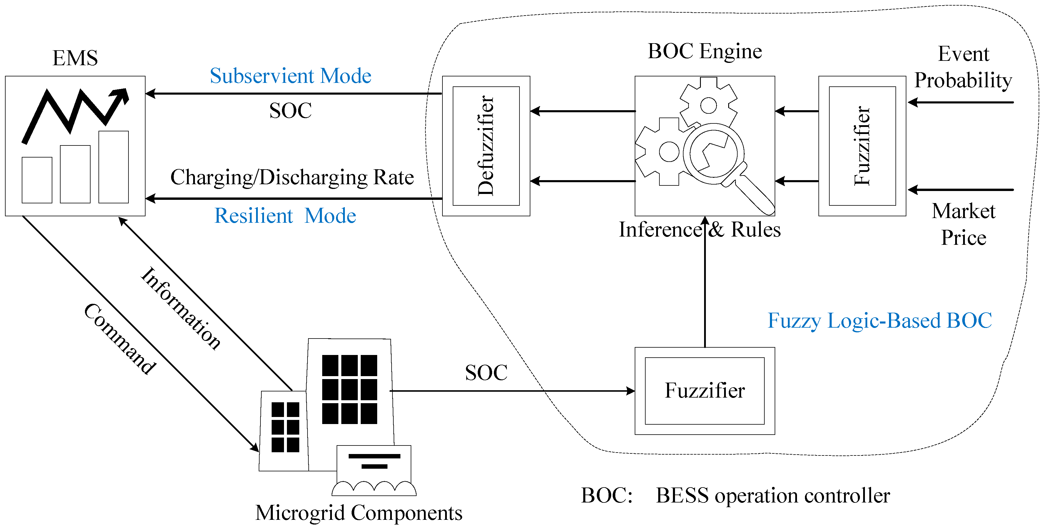
The EMS is primarily responsible for receiving the status of both the microgrids’ components and for scheduling them. All the components obey the commands received from the EMS. However, each BESS unit is equipped with a BESS operation controller. The BESS operation controller is based on fuzzy logic and it decides the operation mode of BESSs. Depending on the input parameters, each BESS unit could be in subservient mode or in resilient mode. BESS operation modes and function of BESS operation controller are explained in the following sections.

2.2. BESS Operation Modes

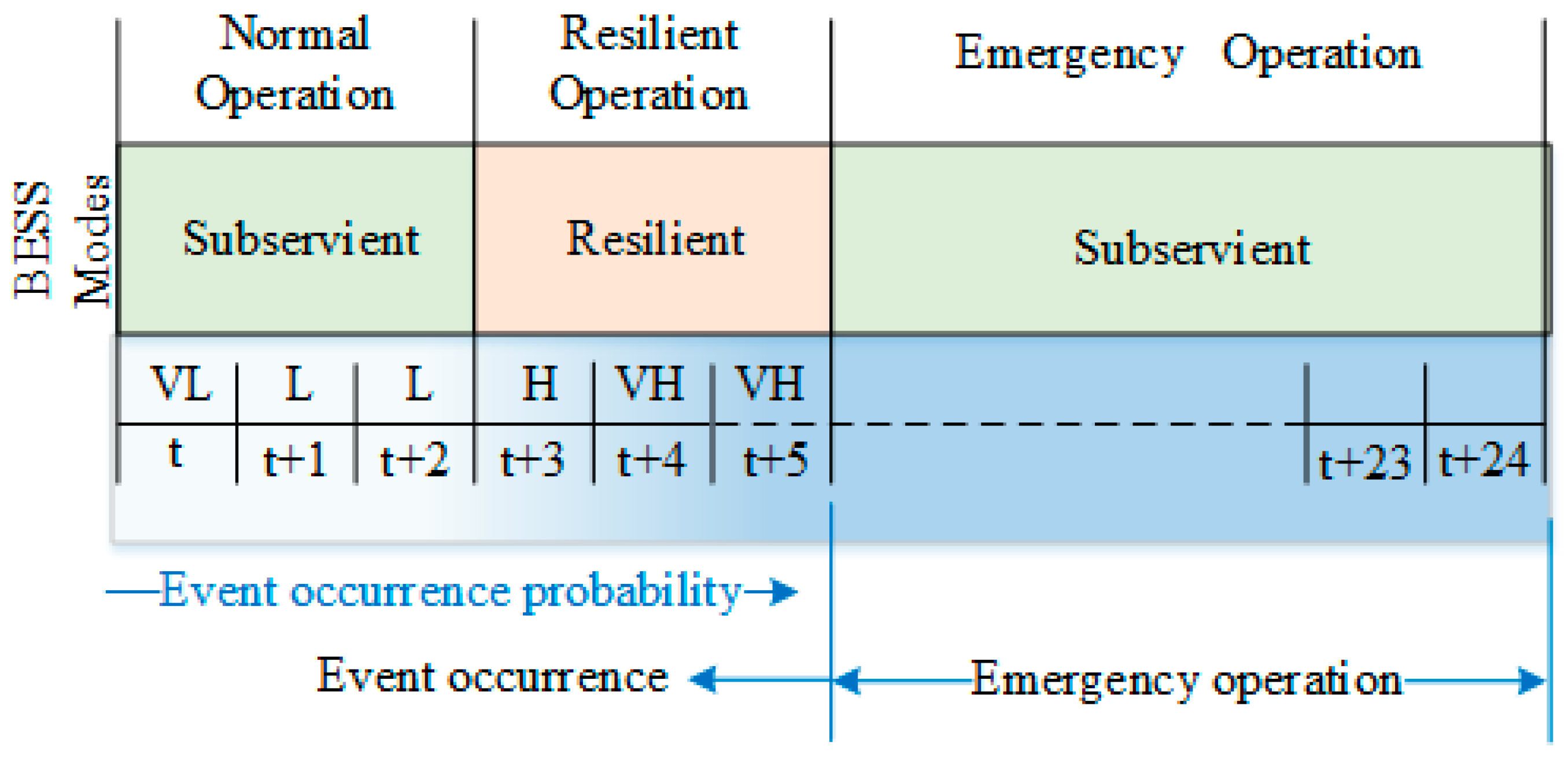
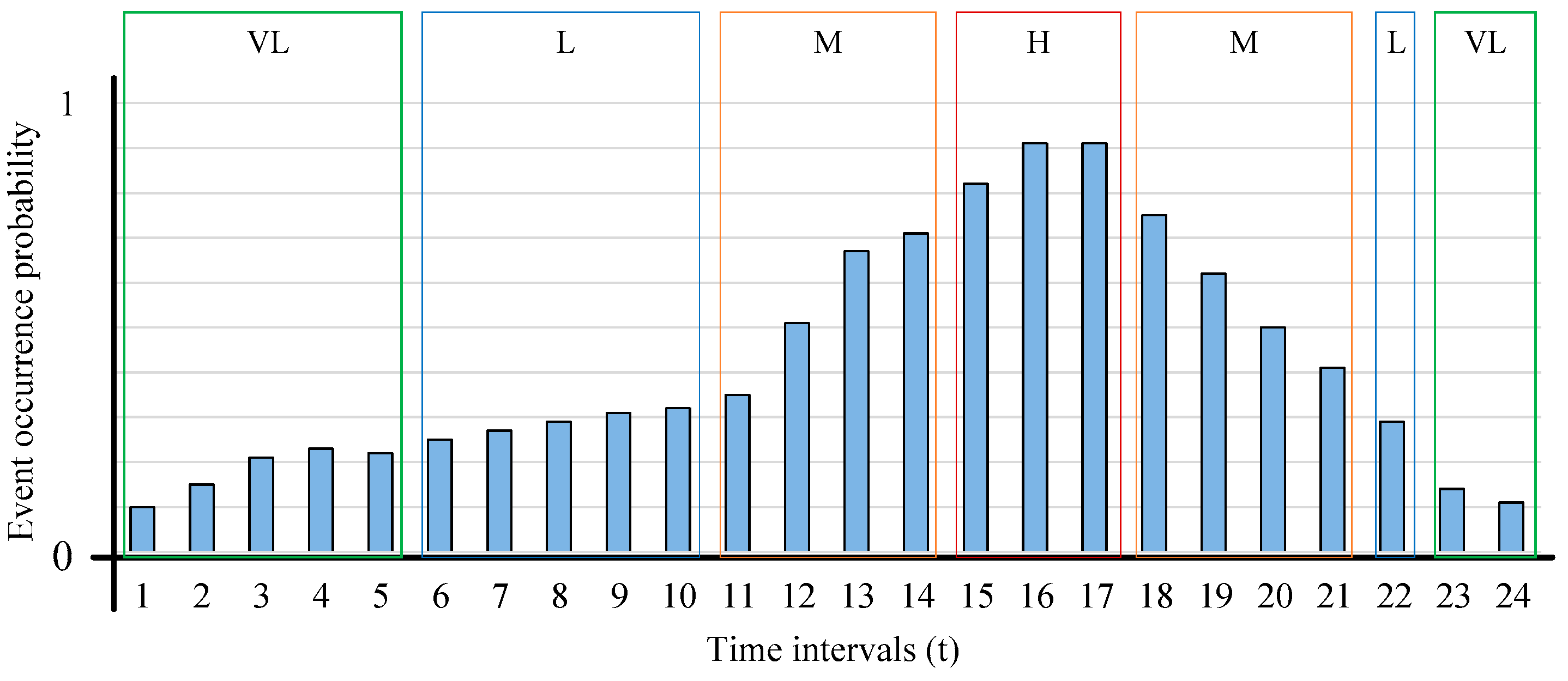
There are three inputs of the BESS operation controller, which is responsible for determining the operation mode of each BESS unit. Event occurrence probability plays a key role in determining the operation mode of BESS; therefore, the other two inputs are ignored in Figure 2. Weather-related events have increased in the past decade and are expected to increase in the future due to climate change. The prediction time regarding the occurrence of different natural/climate-related events is tabulated in [10]. National metrological agencies are responsible for initial warnings concerning weather-related events. Ground-based radars and satellite data are mostly used to monitor the global weather [23]. Once any warning is issued regarding a particular event, it is continuously monitored. Based on the speed and direction of the related parameters (wind, water, seismic activities, etc.), the probability of hitting a particular area at a given time can be expressed as very low (VL), low (L), medium (M), high (H), or very high (VH). BESS operation controller uses the membership level information of event occurrence probability along BESS SOC and market price signals to determine the operation modes of BESS units. The two possible modes suggested in this study for BESS are subservient mode and resilient modes. In subservient mode, the BESS is fully controlled by the EMS. The charging/discharging and rates are determined by the EMS and the BESS follows the commands of the EMS. However, in resilient mode, the BESS decides either to charge/discharge following certain charging/discharging rates and informs the EMS. The EMS accordingly considers the BESS as a resource if it is in discharging mode and considers as a load if it is in charging mode. It can be observed from Figure 2 that when the event occurrence probability is L or VL, the BESS operation controller has decided to be in subservient mode. However, when the event occurrence probability is H or VH, the BESS will switch to resilient mode. Finally, when the event occurs, the BESS will switch back to the subservient mode in order to minimize load shedding. The decision of the BESS operation mode does not only depend on event occurrence probability. Two other inputs also play a minor role in deciding BESS operation mode, which will be discussed in later sections.

2.3. Interaction between the EMS and the BESS Operation Controller

The interaction between the EMS and a fuzzy logic-based BESS operation controller is shown in Figure 3. The BESS operation controller receives market price signals, event occurrence probability, and BESS SOC as crisp inputs. Market price signals are provided by the utility grid, BESS SOC is obtained from the microgrid components, and event occurrence probability can be obtained by using the method described in the previous section. The fuzzifier transforms the inputs to membership functions and forwards the degree of membership related to their respective input parameters to the BESS operation controller engine (fuzzy inference engine). The inference engine evaluates the defined rules and decides the operation mode and charging/discharging with corresponding rates. If subservient mode is selected, only SOC information of the BESS is sent to the defuzzifier. However, in the case of resilient mode, charging/discharging mode and charging/discharging rates along with respective mode is sent to the defuzzifier. The defuzzifier receives the degree of membership of outputs from the inference engine, transforms them into output signals, and informs the EMS. Once the operation mode is decided by the BESS operation controller, the EMS schedules the remaining components accordingly and informs them as shown in Figure 3.
Figure 4 shows the flowchart of the proposed resiliency-oriented operation of hybrid microgrids. Each BESS unit can operate in either subservient mode or in resilient mode. The EMS can operate in one of the three modes, i.e., normal mode, emergency mode, and resilient mode. The step-by-step command/action follow of the proposed algorithm is as follows:
  • EMS receives the information about the components of the microgrid and shares the required information (market price and BESS SOC) with the BESS operation controller.
  • The BESS operation controller receives event occurrence information from a separate entity and also uses the information provided by the EMS and decides the operation modes of the BESS units.
  • The BESS operation controller informs the EMS about the decided operation modes of the BESS units and related information i.e., BESS SOC or charging/discharging rates.
  • In the subservient mode, the BESS follows the commands of the EMS while in the case of resilient mode, the EMS charges/discharges the BESS units according to the rates decided by the BESS operation controller.
  • The EMS evaluates the operation mode of microgrid and chooses one of the three optimization algorithms, as formulated in Section 3.
  • After optimization, all the components of the microgrid are informed with the optimal results by the EMS.
  • The same process is repeated till the end of the scheduling horizon.

2.4. Scheduling Horizons

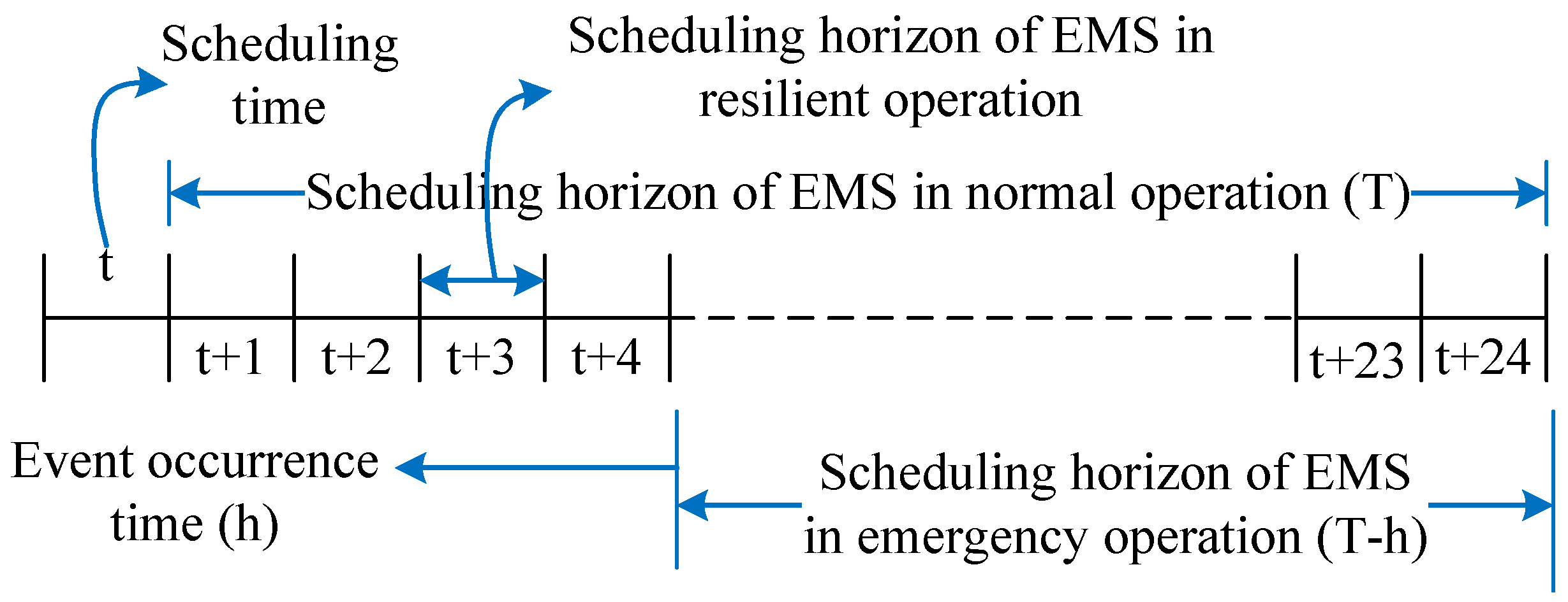
The three possible operation modes of the proposed hybrid microgrid are normal mode (grid-connected mode), resilient mode, and emergency mode (islanded mode). Each of the operation modes has a different scheduling horizon as depicted in Figure 5. The scheduling horizon for normal mode is 24 h (T) and operation is based on the day-ahead model. If the BESS operation controller decides to be in resilient mode, the EMS also switches its mode to resilient mode. The scheduling horizon for resilient mode is one hour (t). The BESS operation controller determines its operation mode at each time interval; therefore, scheduling horizon of the resilient mode is taken as one hour in this study. If any event occurs at time h, the EMS will switch its operation mode to emergency mode. The scheduling horizon of the emergency mode is from t = h to the end of the day (T), i.e., T-h. If the event is cleared, the EMS will switch back to normal/resilient operation mode depending on its input values. Generally, a scheduling horizon of 1 day is considered for scheduling of microgrids [6,8,21]. Therefore, in this study also, simulations are conducted for one day. However, the formulated mathematical models can be used to extend the simulations for longer durations by iterating the scheduling window.

3. Problem Formulation

In this section, mathematical models are developed for all the three operation modes of the EMS. All the developed models are based on mixed integer linear programming with respective scheduling horizons, as explained in the previous section.

3.1. Normal Operation

3.1.1. Objective Function

The objective of the normal operation is to minimize the operation cost of the hybrid microgrid. In addition to electricity transfer between the AC and DC microgrids, electricity can also be traded with the utility grid. The first term of the objective function contains generation cost, start-up cost, and shutdown cost of AC side CDGs. The second term contains generation cost, start-up cost, and shutdown cost of DC side CDGs. The third and fourth terms contain profit gained by trading electricity with the utility grid:
min t = 1 T g a c = 1 G a c ( C g a c C D G ( P g a c ,   t C D G ) + y g a c , t . C g a c S U + z g a c , t . C g a c S D ) +   t = 1 T g d c = 1 G d c ( C g d c C D G ( P g d c ,   t C D G ) + y g d c , t . C g d c S U + z g d c , t . C g d c S D ) +   t = 1 T P R t B U Y . P t B U Y       t = 1 T P R t S E L L . P t S E L L

3.1.2. Load Balancing Constraints

Equation (2) shows the power balance for AC side microgrid. The electricity generated by RDGs, AC side CDGs, power traded with the utility grid, power transferred between AC & DC microgrids, and BESS charging/discharging should be equal to the AC side load. Similarly, DC side load balancing is given by Equation (3). The total amount of electricity bought by both microgrids (AC and DC) can be computed by using (4) and the total amount of electricity sold to the utility grid by (5), where η I L C is the efficiency of the interlinking converter. The amount of electricity transferred between AC and DC side microgrids is given by (6) and it constrained by the capacity of interlinking converter, as given by Equation (7):
P t   A R G + g a c G a c P g a c ,   t   C D G + P t   A B U P t   A S E + P t   F D C . η I L C P t   T D C + P t   A B D P t   A B C = P t   A C L
P t   D R G + g d c G d c P g d c ,   t   C D G + P t   D B U P t   D S E + P t   F A C . η I L C P t   T A C + P t   D B D P t   D B C = P t   D C L
P t B U Y = P t A B U + P t D B U η I L C
P t S E L L = P t A S E + P t D S E . η I L C
P t   F D C = P t   T A C . η I L C ,   P t   F A C = P t   T D C . η I L C
P t   T D C , P t   T A C P c a p   I L C

3.1.3. Constraints for Controllable Generators

Equations (8)–(12) show the imposed constraints for distributed controllable generators. In Equation (8), u g , t is a binary variable and it shows the commitment status of gth CDG at time interval t . If CDG is committed to operate at time t , this binary variable takes the value of 1 and 0 otherwise. Power generation limits of gth CDG are given by Equation (8). Equation (9) shows the start-up indicator ( y g , t ) for gth CDG and Equation (10) shows the shutdown indicator ( z g , t ). If the gth CDG is started up at time t, start-up indicator will take the value of 1 and zero otherwise. Similarly, the shutdown indicator will take a value of 1, if the gth CDG is shut-down at time t and zero otherwise [24]. The ramp-up constraints for gth CDG unit are given by Equation (11) and ramp-down constraints are given by Equation (12):
u g , t .   P g , min   C D G   P g , t   C D G u g , t .   P g , max   C D G
y g , t = max { ( u g , t u g , t 1 ) ,   0 }
z g , t = max { ( u g , t 1 u g , t ) ,   0 }
P g , t   C D G P g , t 1   C D G R U g . ( 1 y g , t ) + P g , min   C D G . y g , t
P g , t 1   C D G P g , t   C D G R D g . ( 1 z g , t ) + P g , min   C D G . z g , t

3.1.4. Battery Constraints

The BESS models for both AC and DC microgrids can be represented by using Equations (13)–(16). X in the BESS model parameters/variables can be replaced by A for an AC microgrid and by D for a DC microgrid. Equation (13) shows that charging of BESS at any time t is constrained by the capacity of the BESS and amount of SOC obtained from a previous time step. Equation (14) shows that discharging amount is constrained by the SOC and capacity of the BESS [25]. Finally, the SOC of the BESS at any time interval t can be computed by using the amount of electricity charged to the BESS, amount of electricity discharged from BESS, and previous interval’s SOC, as given by (15). The SOC of the BESS at any time interval t is constrained by Equation (16):
0 P t X B C P c a p X B . ( 1 S O C t 1 X B ) . 1 1 P l o s s X B C
0 P t X B D P c a p X B . S O C t 1 X B . ( 1 P l o s s X B D )
S O C t X B = S O C t 1 X B 1 P c a p X B . ( 1 1 P l o s s X B D . P t X B D ( 1 P l o s s X B C ) . P t X B C )
S O C min X B S O C t X B S O C max X B

3.2. Resilient Mode

The resilient mode is also a grid-connected mode while the BESS is being controlled by the BESS operation controller. The BESS operation controller decides the charging and discharging rates for the current time interval and informs the EMS.

3.2.1. Objective Function

The objective of the resilient mode is to minimize the operation cost of the microgrid for the given time interval while fulfilling the BESS operation constraints provided by the BESS operation controller. The first term of the objective function contains generation cost, start-up cost, and shutdown cost of AC side CDGs. The second term contains generation cost, start-up cost, and shutdown cost of DC side CDGs. The third and fourth terms contain profit gained by trading electricity with the utility grid at given time interval t:
min g a c = 1 G a c ( C g a c C D G ( P g a c ,   t   C D G ) + y g a c , t . C g a c S U + z g a c , t . C g a c S D ) +   g d c = 1 G d c ( C g d c C D G ( P g d c ,   t   C D G ) + y g d c , t . C g d c S U + z g d c , t . C g d c S D ) + ( P R t B U Y . P t B U Y ) ( P R t S E L L . P t S E L L )

3.2.2. BESS Charging/Discharging Rate Constraints

In resilient mode, the major factor is to incorporate the charging and discharging rates determined by the BESS operation controller. The EMS follows the commands received from the BESS operation controller and schedules other resources accordingly. Charging and discharging rates of a battery are governed by the Coulomb rates (C-rates) [26,27]. The constraint for C-rate of charging ( κ C ) is given by Equation (18). The output of BESS operation controller could be very high (VH), high (H), low (L), or very low (VL). Inference engine transform these values into κ C values as shown below:
P t B C   κ C . P c a p B ,   where   κ C = { 1.0   :   Charging   rate   V H 0.75   :   Charging   rate   H 0.5   :   Charging   rate   L 0.25   :   Charging   rate   V L
Similarly, the C-rate for discharging ( κ D ) of BESS can be calculated by using Equation (19). EMS is informed with the C-rates by BESS operation controller in the resilient mode. Similar to charging case, VH, H, L, and VL is transformed to their corresponding κ D values, as shown below. If the BESS is already fully charged, the BESS operation controller will set the BESS mode to idle (neither charge nor discharge) to use it if any disturbance event occurs:
P t B D   κ D . P c a p B ,   where   κ D = { 1.0   :   Discharging   rate   V H 0.75   :   Discharging   rate   H 0.5   :   Discharging   rate   L 0.25   :   Discharging   rate   V L

3.2.3. Other Constraints

The resilient model is also constrained to the load balancing equations, Equations (2)–(7), and dispatchable generators constraints, Equations (8)–(12). In addition to the BESS constraints explained in the above section, the BESS model is also constrained by Equations (13)–(16).

3.3. Emergency Mode

The scheduling horizon of emergency operation is from the event occurrence time (h) to the end of the day (T). When the emergency is cleared, the EMS will switch back to normal/resilient operation mode depending on the decision of the BESS operation controller. The objective of the emergency mode operation is to minimize the load shedding during the emergency period. Therefore, the penalty for load shedding is considered as higher than the generation cost of the most expensive CDG unit.

3.3.1. Objective Function

The first term of the objective function (20) contains generation cost, start-up cost, and shutdown cost of AC side CDGs. The second term contains generation cost, start-up cost, and shutdown cost of DC side CDGs. The third term contains the penalty cost for shedding load. The total amount of load shed at a time interval t can be obtained by using Equation (21). Due to the inconvenience caused by the load shedding to the consumers, it is considered as a last resort in microgrids to satisfy load balancing. The objective of the emergency operation is to survive maximum possible loads to reduce discomfort and economic losses. Therefore, similar to [5], the penalty cost for curtailing loads is assumed higher than the generation cost of CDGs in this study. Due to this assumption, the priority of service reliability will be higher than the operation cost in the emergency mode:
min t = h T g a c = 1 G a c ( C g a c C D G ( P g a c ,   t C D G ) + y g a c , t . C g a c S U + z g a c , t . C g a c S D ) +   t = h T g d c = 1 G d c ( C g d c C D G ( P g d c , t   C D G ) + y g d c , t . C g d c S U + z g d c , t . C g d c S D )   +   t = h T C   P E N . P t   S H
P t   S H = P t   A S H + P t   D S H

3.3.2. Load Balancing Constraints

In emergency mode, the amount of power generated by AC side RDGs, AC side CGDs, the amount of power transferred between AC and DC microgrids, and amount of load shed should be balanced with total AC-side load, as given by (22). Similarly, DC side load balancing is determined by using Equation (23). In addition to these constraints, load balancing in emergency mode is also constrained to Equations (6) and (7):
P t   A R G + g a c G a c P g a c ,   t   C D G + P t   F D C . η I L C P t   T D C + P t   A B D P t   A B C + P t   A S H = P t   A C L
P t   D R G + g d c G d c P g d c ,   t   C D G + P t   F A C . η I L C P t   T A C + P t   D B D P t   D B C   +   P t   D S H = P t   D C L

3.3.3. Other Constraints

The emergency mode objective function is also constrained by dispatchable generators constraints, Equations (8)–(12). Similarly, the BESS constraints should also be met by the emergency mode operation as given by Equations (13)–(16).

4. Numerical Simulations

The test system considered for simulations, in this study, is similar to that of Figure 1. Two test cases are considered for evaluating the feasibility of the proposed resiliency-oriented optimization method. In the first case, normal operation mode is considered and performance of the proposed and conventional methods is compared. In the second case, emergency mode operation is considered and performance of the proposed and conventional approaches is compared.

4.1. Input Parameters

The hourly electric load of AC and DC microgrids along with output power of respective renewable energy sources are taken as inputs and are tabulated in Table 1. The time-of-use market price signals are also taken as inputs and are shown in Table 1. All the input parameters as mentioned in Table 1 and the system parameters tabulated in Table 2 are taken from [9].
The AC microgrid contains a BESS unit, two CDG units, a wind turbine, and AC loads. Similarly, the DC microgrid contains a BESS unit, two CDG units, PV, and DC loads. Similar to [9], both the AC and DC microgrids are linked via an interlinking converter having an efficiency of 98%. As shown in Figure 1, the AC microgrid is connected to the utility grid and EMS is responsible for scheduling the hybrid microgrid. The test system used for simulations in this study is same with that of Figure 1.
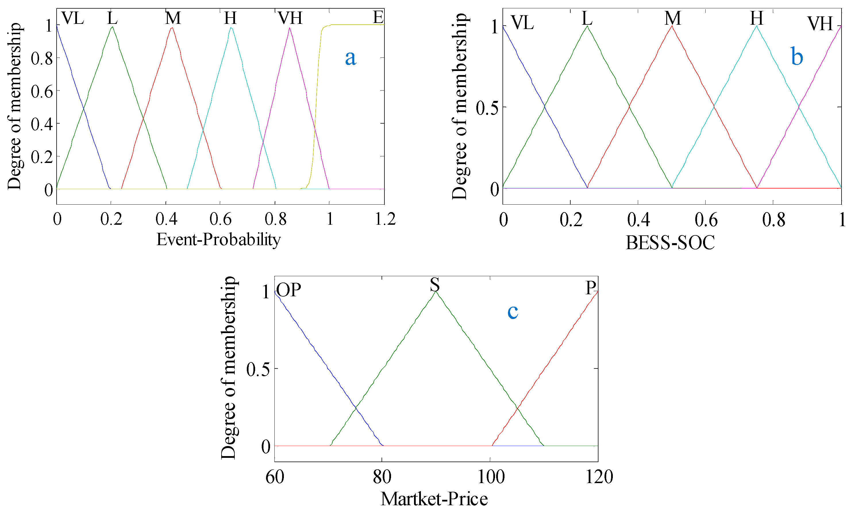
The input membership functions of the BESS operation controller are shown in Figure 6. In contrast to crisp/classical data sets, where either an element is fully a member of a set or fully not, fuzzy sets contain elements with varying degree of memberships [28]. Similarly, any element could be a member of different membership functions at the same time, i.e., 0.6 BESS SOC will belong to M and H by 0.5 degrees. The event probability is assigned into six membership sets listed as very low (VL), low (L), medium (M), high (H), very high (VH), and event (E). The event occurrence probability is shown up to 1.2 for the sake of visibility of the E membership function. However, this value cannot exceed one for all the cases. The actual SOC is taken as input and is assigned into VL, L, M, H, and VH membership sets. The time-of-use market price signals are assigned into three membership sets listed as off-peak (OP), shoulder (S), and peak (P) prices.

4.2. Control Surfaces for BESS Operation Controller

There are there input membership functions of the BESS operation controller, namely, event occurrence probability, BESS SOC, and market price. The output membership functions of the BESS operation controller are also three which are charging/discharging of BESS, charging/discharging rate, and the operation mode of BESS (subservient or resilient). The role of fuzzy logic inference engine is to map each input set to a corresponding output set. This mapping is based on the rules defined in the inference engine. The control surfaces depict the triggering of rules corresponding to different input combinations. Therefore, two of the inputs are selected at a time and control surfaces for all the three outputs are analyzed. The three inputs can make three possible combinational pairs which are shown if Figure 7, Figure 8 and Figure 9. The focus of this study is to prepare the microgrid for a feasible islanding. Therefore, discharging of BESS is not considered in this study.
It can be observed from Figure 7a that when the event probability is H or VH and BESS SOC is VL, L, or M, BESS charging mode is selected. However, with the same event occurrence probability, if the BESS SOC is H or VH, BESS is moving towards the idle mode. Figure 7b shows that when BESS SOC is VL, or L and event probability is M, H, or VH, higher charging rate is selected. However, if the event probability is VL or L, subservient mode is selected by the BESS operation controller as shown in Figure 7c. When the event probability is H or VH, resilient mode of BESS is selected irrespective of the BESS SOC. The control surface of event probability and market price, Figure 8a, is similar to that of BESS SOC and event probability, Figure 7a. If the event probability is M and market price is OP, higher charging rate is selected as shown in Figure 8b. If the event probability is H or VH, higher charging rate is selected irrespective of the market price signals. If the event probability is VL, L, or E, subservient mode is selected irrespective of the market price signal as shown in Figure 8c. However, if event occurrence probability is M, the effect of market price signal on operation mode is evident from Figure 8c. Charging mode is always selected for all possible combinations of market price and BESS SOC as shown in Figure 9a. When BESS SOC is H or VH and market price is H, charging rate is very low as shown in Figure 9b When BESS SOC is VL or L and market price is OP, higher charging rates are selected. For all other combinations, the charging rates are in-between. Only BESS SOC and market price cannot decide the mode of BESS; therefore, there is no change in the control surface for all possible combinations, as shown in Figure 9c.

4.3. Normal Operation Mode

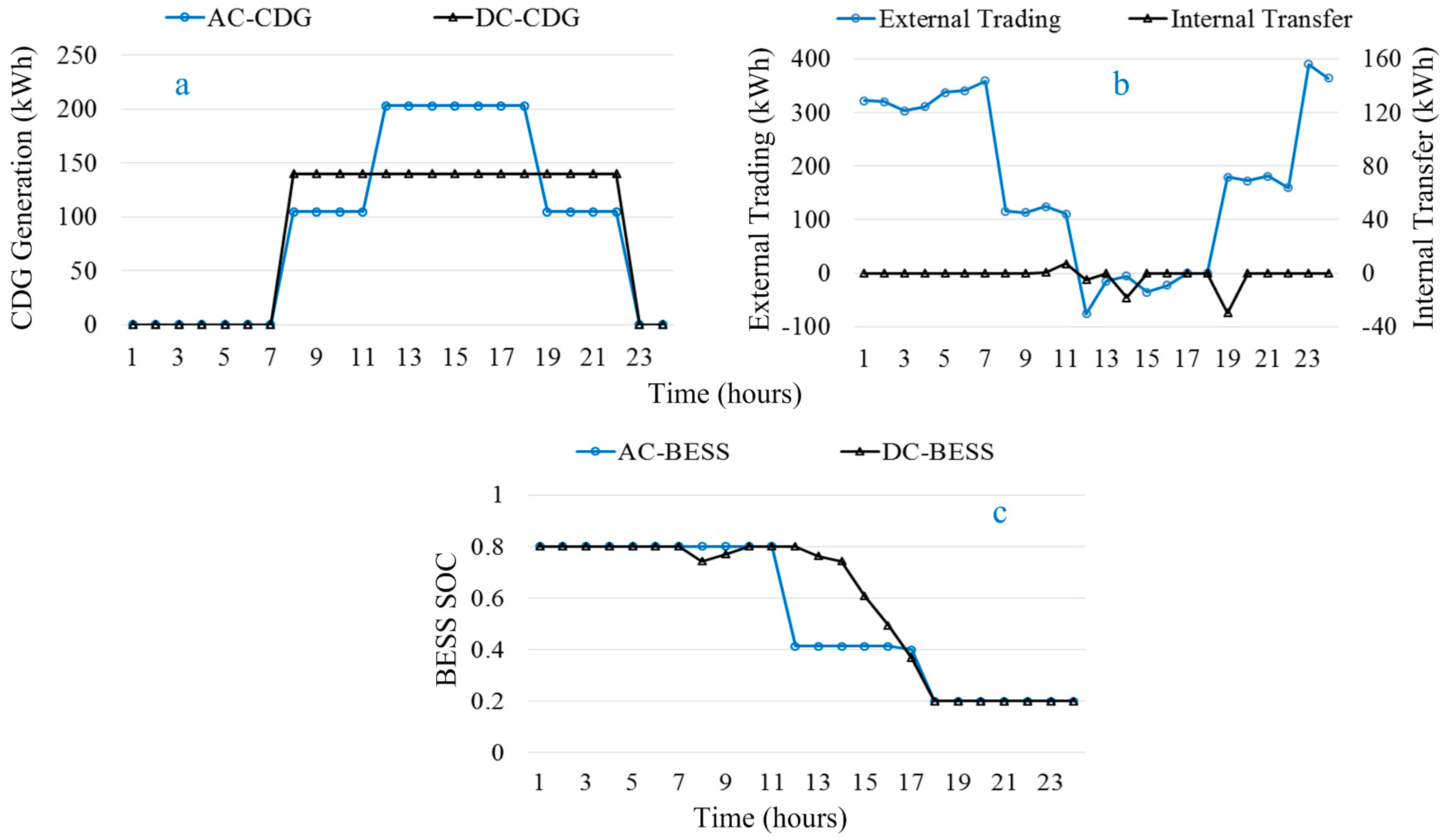
In normal operation mode, two cases are simulated. In the first case, the resilient operation mode of BESS is not considered and BESS is always fully controlled by EMS, which is named as conventional approach. In the second case, proposed method is implemented and BESS operation mode is decided by BESS operation controller, which is named as proposed strategy. The simulated scenario for evaluating the performance of proposed strategy is shown in Figure 10. Interval-wise event occurrence probability considered for this case is shown in Figure 10. Market price signals are taken from Table 1 and actual SOC is used for each time interval.
It can be observed from Figure 11a that the generation amount of CDGs is controlled by the market price signals. During off-peak intervals, CDGs are set to minimum and demand is fulfilled by buying electricity from the utility grid in order to minimize the microgrid’s operation cost. In peak price intervals, CDGs are set to maximum and surplus is sold to the utility grid to increase the profit. External trading is increasing during off-peak intervals due to buying of more electricity from the utility grid as depicted in Figure 11b. However, internal transfer (between AC and DC microgrids) can be seen during peak price intervals to avoid external trading. BESS units are charged during the off-peak intervals and are discharged during the peak price intervals as depicted in Figure 11c. The BESS is used either to fulfill the local demand of microgrid or to trade power with the utility grid.
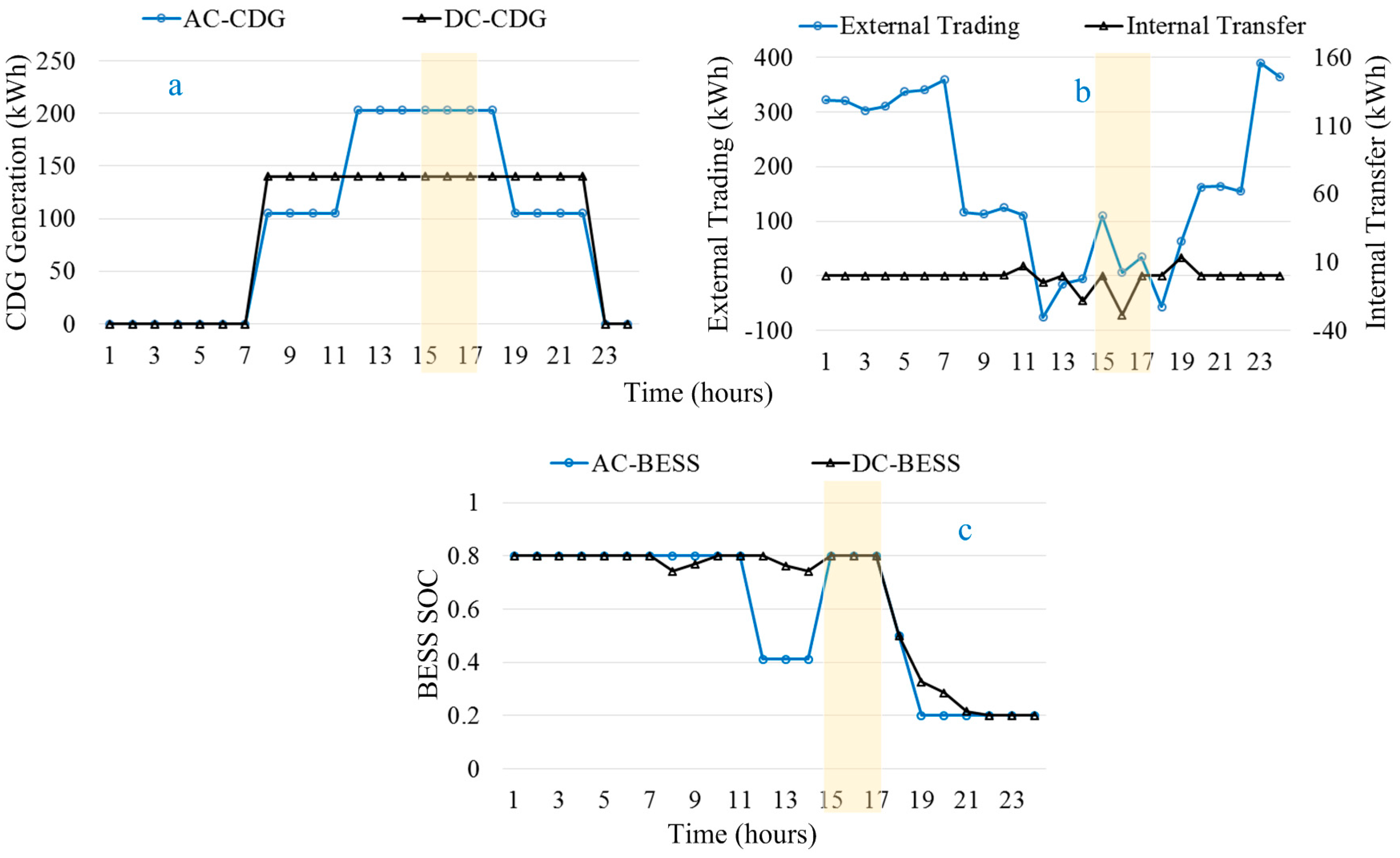
In the case of the proposed strategy, generation pattern of CDGs is identical to that of the conventional approach, as shown in Figure 12a. During time intervals 1–14, the event occurrence probability is VL, L, or M; therefore, subservient mode has been selected by the BESS operation controller. The operation results of the conventional approach and proposed strategy are same during those intervals. However, event occurrence probability has changed to H during time intervals 15–17. BESS operation controller has switched to resilient mode during these intervals. Electricity has been bought from the utility grid to charge the BESS units as depicted in highlighted part of Figure 12b. BESS has not been allowed to discharge during these time intervals as highlighted in Figure 12c. However, event occurrence probability has again dropped to M, L, and VL during time intervals 18–24. BESS operation controller has switched back to subservient mode during those time intervals. BESS is discharged during the remaining time intervals to fulfill the load demands of the microgrid.
A summary of the results for both the conventional case and the proposed strategy during the entire scheduling horizon are tabulated in Table 3. The amount of CDGs generation is same in both the cases while internal trading is increased in the case of the proposed strategy. External trading is similar while operation cost has increased for the proposed strategy due to consideration of the resilient mode operation.
Due to the consideration of resilient operation mode, more electricity has been bought from the utility grid during peak price intervals to charge the BESS units. Due to this consideration, operation cost has increased from 895,255.1 KRW to 898,796.7 KRW, which is an increase of 0.394%. However, it will result in the reduction of load shedding during system disturbances. Additionally, this increase in operation cost depends on the SOC of BESS units conceded from previous time interval.

4.4. Emergency Operation Mode

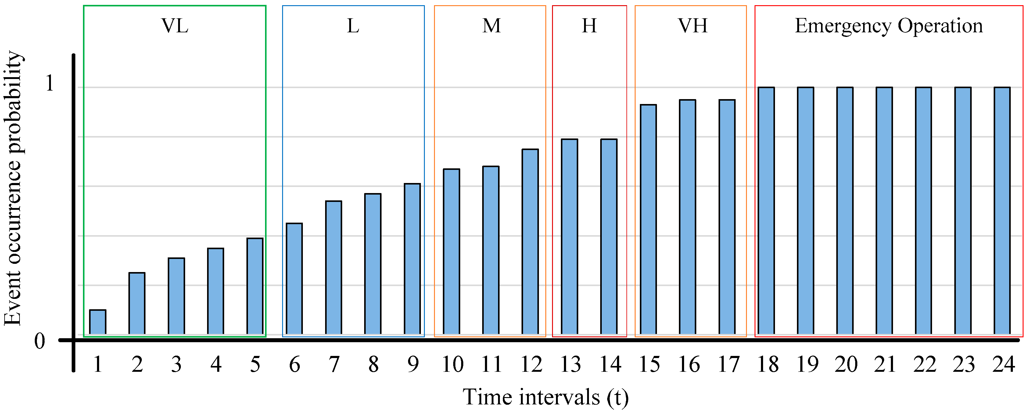
In emergency mode also, two cases are simulated. In the first case, The BESS is always fully controlled by the EMS, which is named the conventional approach. In the second case, the BESS operation controller decides the operation mode (resilient or subservient) of the BESS, which is named as proposed strategy. The simulated scenario for evaluating the performance of proposed strategy in emergency mode is shown in Figure 13, where interval-wise event occurrence probability is shown.
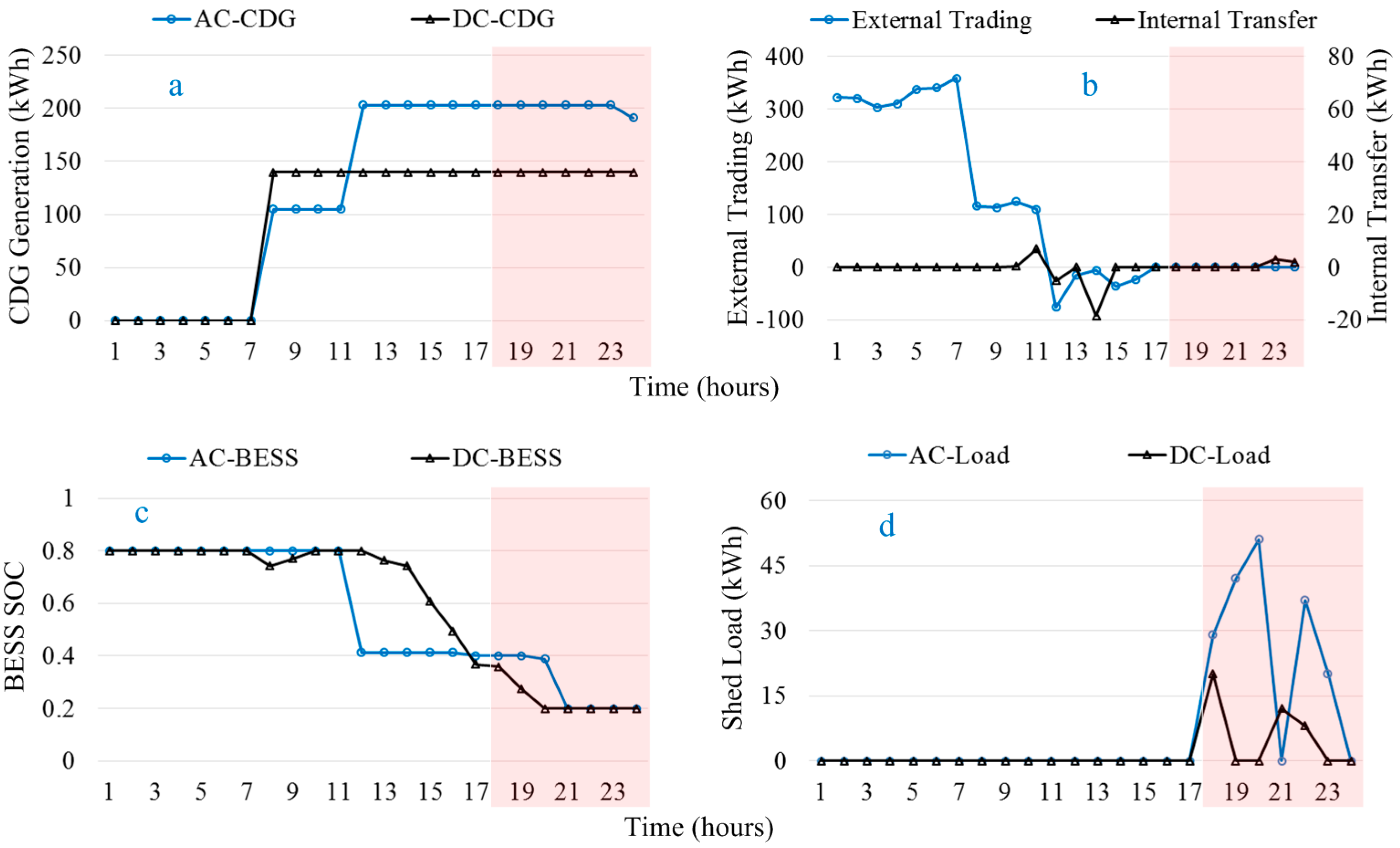
The system was in grid-connected mode during time intervals 1–17. Due to a system disturbance event, operation mode of the system has changed to islanded mode in time interval 18 and remained in islanded mode until the end of the day (24 h), as highlighted in Figure 14. During grid-connected mode, generation of CDGs is controlled by the market price signals as shown in Figure 14a. However, during emergency mode, CDGs generate maximum power to minimize load shedding. External trading is not possible during islanded mode as shown in highlighted portion of Figure 14b. In the case of conventional approach, system resiliency is not considered and the BESS is discharged during peak price intervals to increase profit as shown in Figure 14c. However, when the system is switched to emergency mode, load shedding is carried out in all the intervals in both AC and DC microgrids, as shown in Figure 14d.
The generation profile of CDGs in the proposed case is similar with that of the conventional approach, as shown in Figure 15a. In contrast to the conventional approach, the BESS operation controller has selected resilient mode during time intervals 13–17, due to H and VH event probability. During resilient operation mode, internal power exchange and external trading are increased, as shown in Figure 15b. The exchanged/traded power is used to charge the BESS units as shown in Figure 14c. It can be observed from Figure 15c that BESS units are not allowed to discharge during emergency mode. When the system is switched to emergency mode at time interval 18, the BESS operation controller has switched operation mode of BESS to subservient mode. EMS has utilized the BESS units to minimize load shedding during emergency period. DC side load shedding is reduced to zero during the emergency period and a limited load shedding is carried out during time intervals 18 and 20 on the AC side, as shown in Figure 15d. Load shedding is reduced from 219.12 kWh to 17.73 kWh by the proposed strategy, which is a decrease by 92%.
Table 4 shows the summary of the results of both the conventional approach and the proposed strategy during the emergency operation mode. The generation amount of CDGs remains same for both the cases. Internal trading is increased during the proposed strategy to minimize load shedding during emergency intervals. External trading is also increased to charge the BESS units during the resilient mode. Finally, load shedding is reduced and it resulted in a reduction of the operation cost due to avoidance of penalty costs.

5. Conclusions

A mathematical framework for enhancing the resiliency of hybrid microgrids is proposed. Fuzzy logic-based BESS operation controller is proposed for determining the operation mode of BESS units. In subservient mode, the BESS is fully controlled by the EMS but in resilient mode, the BESS operation controller decides the charging/discharging along with their respective rates. In normal operation mode, due to consideration of resilient operation mode, operation cost has increased by 0.394%. However, this consideration can mitigate the curtailment of the load during emergency operation. In emergency operation, BESS mode is switched to subservient mode and the EMS uses the stored energy for reducing load shedding. During emergency operation, load shedding can be reduced by 92% by using the proposed strategy. It can be concluded that the proposed strategy operation barely increases cost while load shedding is considerably reduced.

Acknowledgments

This work was supported by the Korea Institute of Energy Technology Evaluation and Planning (KETEP) and the Ministry of Trade, Industry & Energy (MOTIE) of the Republic of Korea (No. 20168530050030).

Author Contributions

The paper was a collaborative effort between the authors. The authors contributed collectively to the theoretical analysis, modeling, simulation, and manuscript preparation.

Conflicts of Interest

The authors declare no conflict of interest.

Abbreviations

t Index of time, running from 1 to T
g ,   g a c ,   g d c Index for total, AC side, and DC side CDGs, respectively ( g g a c ,     g d c )
u g , t ,   y g , t ,   z g , t Commitment, startup, and shutdown status identifier of gth CDG at t
C g C D G ( P g ,   t   C D G ) Generation cost of CDG unit g at t
C g S U , C g S d Start-up and shutdown cost of CDG unit at t
P R t B U Y , P R t S E L L Price for buying and selling power to/from the utility grid at t
P g ,   t   C D G Amount of power generated by CDG g at t
P t B U Y , P t S E L L Total amount of power bought from and sold to the utility grid at t
P t   A B U , P t   A S E Amount of power bought from and sold to the utility grid by AC microgrid at t
P t   D B U , P t   D S E Amount of power bought from and sold to the utility grid by DC microgrid at t
P t   A C L ,   P t   D C L Forecasted electric load of AC and DC side microgrids at t
P t   F D C ,   P t   F A C Amount of power transferred from DC to AC and AC to DC microgrids at t
P t   A R G ,   P t   D R G Amount of power generated by AC and DC side RDG units at t
P c a p   I L C ,   η I L C Capacity and efficiency of interlinking converter
P g ,   min   C D G ,   P g ,   max   C D G Minimum and maximum generation amount of gth CDG unit
R U g ,   R D g Ramp-up and Ramp-down time of gth CDG unit
P t X B C , P t X B D   Amount of electrical energy charged/discharged to/from BESS at t
P l o s s X B C , P l o s s X B D Charging and discharging losses of X-type BESS unit
P c a p X B ,   S O C t X B Capacity and SOC of BESS X-type BESS unit
S O C min X B ,   S O C max X B Lower and upper limits for SOC of X-type BESS unit
κ C ,   κ D C-rates for charging and discharging of BESS units
P t   A S H , P t   D S H Amount of load shed from AC and DC side microgrids at t
P t   S H ,   C   P E N Total amount of shed load and penalty cost for load shedding at t

References

  1. Khodaei, A. Resiliency-oriented microgrid optimal scheduling. IEEE Trans. Smart Grid 2014, 5, 1584–1591. [Google Scholar] [CrossRef]
  2. Arghandeh, R.; Von, M.A.; Mehrmanesh, L.; Mili, L. On the definition of cyber-physical resilience in power systems. Renew. Sustain. Energy Rev. 2016, 58, 1060–1069. [Google Scholar] [CrossRef]
  3. Simonov, M. Dynamic partitioning of DC microgrid in resilient clusters using event-driven approach. IEEE Trans. Smart Grid 2014, 5, 2618–2625. [Google Scholar] [CrossRef]
  4. Schneider, K.; Tuffner, F.; Elizondo, M.; Liu, C.C.; Xu, Y.; Ton, D. Evaluating the feasibility to use microgrids as a resiliency resource. IEEE Trans. Smart Grid 2016, 8. [Google Scholar] [CrossRef]
  5. Hussain, A.; Bui, V.H.; Kim, H.M. A resilient and privacy-preserving energy management strategy for networked microgrids. IEEE Trans. Smart Grid 2016, pp. [Google Scholar] [CrossRef]
  6. Wang, Z.; Chen, B.; Wang, J.; Chen, C. Networked microgrids for self-healing power systems. IEEE Trans. Smart Grid 2016, 7, 310–319. [Google Scholar] [CrossRef]
  7. Wang, Z.; Wang, J. Self-healing resilient distribution systems based on sectionalization into microgrids. IEEE Trans. Power Syst. 2015, 30, 3139–3149. [Google Scholar] [CrossRef]
  8. Balasubramaniam, K.; Saraf, P.; Hadidi, R.; Makram, E.B. Energy management system for enhanced resiliency of microgrids during islanded operation. Electr. Power Syst. Res. 2016, 137, 133–141. [Google Scholar] [CrossRef]
  9. Hussain, A.; Bui, V.H.; Kim, H.M. Optimal operation of hybrid microgrids for enhancing resiliency considering feasible islanding and survivability. IET Renew. Power Gener. 2017. [Google Scholar] [CrossRef]
  10. Wang, Y.; Chen, C.; Wang, J.; Baldick, R. Research on resilience of power systems under natural disasters—A review. IEEE Trans. Power Syst. 2016, 31, 1604–1613. [Google Scholar] [CrossRef]
  11. Panteli, M.; Mancarella, P. Influence of extreme weather and climate change on the resilience of power systems: Impacts and possible mitigation strategies. Electr. Power Syst. Res. 2015, 127, 259–270. [Google Scholar] [CrossRef]
  12. Mahmoud, M.S.; Fouad, M. Control and Optimization of Distributed Generation Systems; Springer: London, UK, 2015. [Google Scholar]
  13. García, P.; Torreglosa, J.P.; Fernández, L.M.; Jurado, F. Optimal energy management system for stand-alone wind turbine/photovoltaic/hydrogen/battery hybrid system with supervisory control based on fuzzy logic. Int. J. Hydrog. Energy 2013, 38, 14146–14158. [Google Scholar] [CrossRef]
  14. Li, S.G.; Sharkh, S.M.; Walsh, F.C.; Zhang, C.N. Energy and battery management of a plug-in series hybrid electric vehicle using fuzzy logic. IEEE Trans. Veh. Technol. 2011, 60, 3571–3585. [Google Scholar] [CrossRef]
  15. Chen, Y.K.; Wu, Y.C.; Song, C.C.; Chen, Y.S. Design and implementation of energy management system with fuzzy control for DC microgrid systems. IEEE Trans. Power Electron. 2013, 28, 1563–1570. [Google Scholar] [CrossRef]
  16. Kyriakarakos, G.; Dounis, A.I.; Arvanitis, K.G.; Papadakis, G. A fuzzy logic energy management system for polygeneration microgrids. Renew. Energy 2012, 41, 315–327. [Google Scholar] [CrossRef]
  17. Sayed, K.; Gabbar, H.A. Electric vehicle to power grid integration using three-phase three-level AC/DC converter and PI-fuzzy controller. Energies 2016, 9, 532. [Google Scholar] [CrossRef]
  18. Koirala, B.P.; Chaves, Á.J.P.; Gómez, T.; Hakvoort, R.A.; Herder, P.M. Local alternative for energy supply: Performance assessment of integrated community energy systems. Energies 2016, 9, 981. [Google Scholar] [CrossRef]
  19. Hosseinzadeh, M.; Salmasi, F.R. Power management of an isolated hybrid AC/DC micro-grid with fuzzy control of battery banks. IET Renew. Power Gener. 2015, 9, 484–493. [Google Scholar] [CrossRef]
  20. Aryani, D.R.; Song, H. Coordination control strategy for AC/DC hybrid microgrids in stand-alone mode. Energies 2016, 9, 469. [Google Scholar] [CrossRef]
  21. Baboli, P.T.; Shahparasti, M.; Moghaddam, M.P.; Haghifam, M.R.; Mohamadian, M. Energy management and operation modelling of hybrid AC–DC microgrid. IET Gener. Transm. Distrib. 2014, 8, 1700–1711. [Google Scholar] [CrossRef]
  22. Liu, Y.; Hou, X.; Wang, X.; Lin, C.; Guerrero, J.M. A coordinated control for photovoltaic generators and energy storages in low-voltage AC/DC hybrid microgrids under islanded mode. Energies 2016, 9, 651. [Google Scholar] [CrossRef]
  23. STI Policy Profiles: Facing New Challenges, Technology to Manage Natural Disasters and Catastrophes. Available online: http://www.wmo.int/pages/index_en.html (accessed on 22 February 2017).
  24. Hussain, A.; Bui, V.H.; Kim, H.M. Robust optimization-based scheduling of multi-microgrids considering uncertainties. Energies 2016, 9, 278. [Google Scholar] [CrossRef]
  25. Hussain, A.; Bui, V.H.; Kim, H.M.; Im, Y.H.; Lee, J.Y. Optimal operation of tri-generation microgrids considering demand uncertainties. Int. J. Smart Home 2016, 10, 131–144. [Google Scholar] [CrossRef]
  26. Battery University-C-Rates. Available online: http://batteryuniversity.com/learn/article/what_is_the_c_rate (accessed on 22 February 2017).
  27. Texas Instruments. Characteristics of Rechargeable Batteries; Texas Instruments: Dallas, TX, USA, 2011. [Google Scholar]
  28. Bai, Y.; Wang, D. Fundamentals of fuzzy logic control—Fuzzy sets, fuzzy rules and defuzzifications. In Advanced Fuzzy Logic Technologies in Industrial Applications; Springer: London, UK, 2006. [Google Scholar]
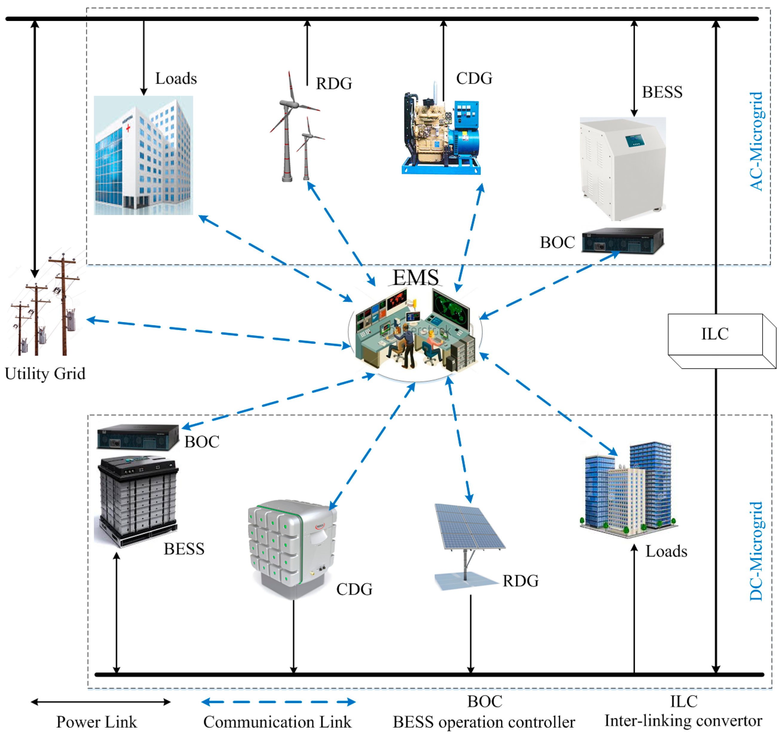
Figure 1. An illustration of a typical hybrid microgrid system.
Energies 10 00271 g001
Figure 2. Battery energy storage system (BESS) operation modes and event occurrence probability.
Energies 10 00271 g002
Figure 3. Fuzzy logic-based BESS operation controller.
Energies 10 00271 g003
Figure 4. Flowchart for interaction between the EMS and the BESS operation controller.
Energies 10 00271 g004
Figure 5. Scheduling horizons of different operation modes of the proposed hybrid microgrid.
Energies 10 00271 g005
Figure 6. Membership functions: (a) event probability; (b) BESS SOC; (c) market price signals.
Energies 10 00271 g006
Figure 7. Control surfaces for BESS operation controller corresponding to event occurrence probability and BESS SOC: (a) charging/discharging mode; (b) charging/discharging rate; (c) BESS operation mode.
Energies 10 00271 g007
Figure 8. Control surfaces for BESS operation controller corresponding to event occurrence probability and market price: (a) charging/discharging mode; (b) charging/discharging rate; (c) BESS operation mode.
Energies 10 00271 g008
Figure 9. Control surfaces for BESS operation controller corresponding to market price and BESS SOC: (a) charging/discharging mode; (b) charging/discharging rate; (c) BESS operation mode.
Energies 10 00271 g009
Figure 10. Simulated scenario for evaluating proposed strategy during normal mode operation.
Energies 10 00271 g010
Figure 11. Operation results of conventional case: (a) CDG generation; (b) power trading; (c) BESS SOC.
Energies 10 00271 g011
Figure 12. Operation results of proposed strategy: (a) CDG generation; (b) power trading; (c) BESS SOC.
Energies 10 00271 g012
Figure 13. Simulated scenario for evaluating proposed strategy during emergency mode operation.
Energies 10 00271 g013
Figure 14. Operation results of conventional case: (a) CDG generation; (b) power trading; (c) BESS SOC; (d) load shedding.
Energies 10 00271 g014
Figure 15. Operation results of proposed strategy: (a) CDG generation; (b) power trading; (c) BESS SOC; (d) load shedding.
Energies 10 00271 g015
Table 1. Forecasted values of load and renewable generations along with the market price.
Time (Hours)Electric Load (kWh)Renewable Power (kWh)Market Price Signals (KRW)
AC-MGDC-MGPVWTBuying PriceSelling Price
12151100510080
22061190710080
319711401010080
420911101210080
52161250610080
62121300410080
72191400310080
822815847115100
922714299115100
102421441212115100
112371471415115100
122341621717135125
132161692028135125
141991821920135125
151811891614135125
161901791110135125
1721417878135125
1825518433135125
1926116906115100
2027415007115100
21280157011115100
22275144015115100
2326514101910080
2423714802410080
Table 2. Parameters related to controllable distributed generators (CDGs) and BESS units of the hybrid microgrid.
MGsBESSCDG1CDG2
P l o s s X B C (%) P l o s s X B D (%) P min X B (kWh) P C a p X B (kWh) P 1 ,   min   C D G (kWh) P 1 ,   max   C D G (kWh) C 1 C D G (KRW/kWh) P 2 ,   min   C D G (kWh) P 2 ,   max   C D G (kWh) C 2 C D G (KRW/kWh)
AC MG2250 2500 105112098118
DC MG2250 250075106065103
Total44100 5000180-0163-
Table 3. Summary of results for the conventional case and the proposed strategy in normal mode.
CasesGeneration (kWh)Internal Trading (kWh)External Trading (kWh)Operation Cost (KRW) *
Conventional436160.484358.85895,255
Proposed436172.964358.1898,797
* Exchange rate.
Table 4. Summary of results for the conventional case and the proposed strategy in emergency mode.
CasesGeneration (kWh)Internal Trading (kWh)External Trading (kWh)Load Shed (kWh)Operation Cost (KRW) *
Conventional5427.0835.892912.73219.2981,143.4
Proposed5427.08169.232969.2617.73919,046.6
* Exchange rate.