Article

An Improved Multi-Infeed Effective Short-Circuit Ratio for AC/DC Power Systems with Massive Shunt Capacitors Installed

1
State Key Laboratory of Advanced Electromagnetic Engineering and Technology, School of Electrical and Electronic Engineering, Huazhong University of Science and Technology, 1037 Luoyu Road, Wuhan 430074, China
2
China Electric Power Research Institute, Haidian District, Beijing 100192, China
*
Author to whom correspondence should be addressed.
Energies 2017, 10(3), 396; https://doi.org/10.3390/en10030396
Submission received: 13 February 2017 / Revised: 11 March 2017 / Accepted: 16 March 2017 / Published: 20 March 2017
(This article belongs to the Section F: Electrical Engineering)

Abstract

:
The multi-infeed effective short-circuit ratio (MESCR) is widely used in indicating the strength of multi-infeed AC/DC power systems. However, when the widely used MESCR was adopted to evaluate the stability margin of the Eastern China Grid including three infeed ultra-high-voltage DC (UHVDC) and five high-voltage DC transmission lines in 2016, the MESCR result indicated the system was strong enough but in fact occasionally collapses after the N-1 contingency. To determine the reason for this conflict, this paper theoretically analyzes the limitations of the existing MESCR. The theoretical analysis reveals that when a large amount of capacitor compensations are concentratively installed in the system, the conventional MESCR will not be able to reflect the capacitor compensations’ influence on the system stability, and no matter how many capacitors are installed or where the capacitors are installed, the MESCR almost retains the same value; namely, the MESCR is saturated in such systems. To address the saturation problem of conventional MESCR, this paper proposes an improved multi-infeed effective short-circuit ratio (IMESCR) which considers the influences of all capacitor compensations by converting all capacitors installed throughout the system to virtual capacitors at the DC inverter station. Case studies are carried out based on the New England 39-bus system and the Eastern China Grid, respectively. The simulation results verify the theoretical analysis of the MESCR’s limitations in evaluating the stability of power systems with massive capacitors installed, and proves that the proposed IMESCR could accurately indicate the strength of AC/DC power systems. Therefore, the proposed IMESCR provides a new index for evaluating the stability margin of power systems with massive capacitor compensations installed.

1. Introduction

With three ultra-high voltage Direct Current (UHVDC, ±800 kV or higher voltage) transmission lines and five high voltage high voltage Direct Current (HVDC, ≤±500 kV) transmission lines fed into the Eastern China Grid (consisting of Shanghai, Jiangsu, Zhejiang, Anhui, and Fujian), the east load center and one of the most prosperous regions in China has inevitably become a typical multi-infeed AC/DC power system. With intensive DC placement and nearly 40 GW of its local load fed by UHVDC and HVDC transmission lines in 2016, the Eastern China Grid is facing significant challenges of maintaining the safe and stable operation of the AC/DC hybrid power system [1,2,3,4].
The short-circuit ratio (SCR) is widely used in the planning process of DC transmissions to evaluate the capability of the AC system in maintaining the stability of the AC/DC system. The effectiveness of SCR in determining the voltage stability and dynamic over-voltage of a single DC infeed system is analyzed in reference [5], and has been validated with enormous practical projects. However, in power systems with multiple DC infeeds, the interactions between DC rectifiers/inverters make the voltage stability analysis much more complex than that of single-DC-infeed systems [6,7,8,9]. When adopting the single-infeed SCR to evaluate the strength of multi-infeed systems, because the single-infeed SCR cannot consider the interactions between different DC transmission lines, the results tend to be too optimistic [10,11]. To provide a reasonable index to assess the strength of multiple DC infeed AC/DC systems, many studies on the SCR for multi-infeed DC systems have been carried out by scholars in various countries [12,13,14,15,16,17,18]. Reference [12] used the mutual impedance to reflect the DC interaction in a multi-infeed AC/DC system, and proposed the definition of Multi-infeed Short Circuit Ratio (MSCR) and Multi-infeed Effective Short Circuit Ratio (MESCR), and this research laid the foundation for adopting the MSCR for analyzing voltage stability in multiple DC infeed systems. In [13], a power-flow model was used as the mathematical framework to derive an analytical equivalent of MSCR, and to facilitate the rigorous analysis of voltage/power interactions in multi-infeed HVDC systems. Reference [14] analyzed the relationship between the MESCR and the DC maximum transmission power, and defined a new MESCR threshold value for the discrimination of the receiving system strength. This research also mentioned that the MESCR still needs to be improved to accurately reflect the system strength. Reference [15] analyzed the influencing factors of MESCR in a two HVDC infeed system, and found that the electrical distance between HVDC terminal stations, network structures, line impedance, and distribution of power resources all could have influences on the MESCR. Based on the MESCR defined in [12], reference [16] proposed a new definition of the MESCR considering different control modes of DC transmission lines. Reference [17] analyzed the influences of reactive compensations installed at the DC inverter stations and defined an extended MESCR that considers the influence in the calculation of the MESCR. However, due to the complexity of the multi-infeed DC system, the discussion and improvement of the MSCR is still in progress [18,19,20].
Until now, the MESCR proposed in [12] is still the most widely used index in multi-infeed DC system planning and analysis. The MESCR proposed in [12] defined a multi-infeed interaction factor (MIIF) to convert the capacity of all other DC transmission lines to the bus under investigation, so that it could consider the interaction between all DC rectifier/inverter stations. However, similar to single-infeed SCR, the MESCR subtracts only the capacity of capacitors installed at the DC rectifier/inverter bus being investigated, while all other reactive compensations including capacitors installed in other DC rectifier/inverter buses and shunt capacitors installed all over the system are ignored in the MESCR calculation.
In modern power systems, shunt capacitors are widely installed to maintain the voltage level of all buses. Due to the large amount of reactive power demanded by the line commutated converter based HVDC (LCC-HVDC), DC rectifier/inverter stations are always installed with a large capacity of capacitors as well. Thus, for the Eastern China Grid which has as many as eight DC transmission lines fed in, there are massive shunt capacitor compensations installed in the system. When adopting the widely used MESCR in evaluating the voltage stability of the Eastern China Grid in 2016, the system has a much higher MESCR index than the recommended threshold for strong systems [12]. However, the system collapsed several times during the N-1 contingency analysis. The conflict between the simulation results and calculated MESCR indicates the existing MESCR still need to be improved to correctly reflect the strength of practical power systems. By analyzing the characteristics of the Eastern China Grid, it is found that the widely installed reactive power compensation facilities heavily affect the voltage stability of the system. The conventional MESCR gets saturated in the Eastern China Grid; namely, the MESCR become insensitive to different capacities of capacitor compensation as well as different capacitor installation locations. Therefore, the existing MESCR might be incapable of accurately indicating the voltage stability in power systems like the Eastern China Grid, which has massive shunt capacitor compensations installed in the system.
In order to address the saturation problem of the existing MESCR in power systems installed with large amount of capacitors, this paper proposes an improved effective short-circuit ratio (IMESCR) that considers the influence of shunt capacitors in the evaluation of the system strength. The proposed IMESCR converts all capacitor compensations throughout the system to virtual capacitors at inverter buses, and then calculates the MESCR with both the virtual compensation and real compensation at the inverter buses considered. A modified New England 39-bus system is adopted for the case study. Through designing cases in different compensation capacities and different compensation locations, the case study results illustrate the saturation phenomenon of conventional MESCR and prove that the proposed IMESCR could correctly indicate the system strength in heavily compensated systems. After that, the feasibility and accuracy of the proposed IMESCR are also validated in the Eastern China Grid.
The major contributions of this paper are three fold:
(a)
The saturation phenomenon of the conventional MESCR in power systems installed with large amount of capacitor compensations is found through theoretical analysis.
(b)
An IMESCR which could overcome the saturation and correctly reflect the stability margin in systems with a large amount of capacitor concentratively installed is proposed.
(c)
The saturation of MESCR and the feasibility of the proposed IMESCR are verified through both the New England 39-bus system and the Eastern China Grid.

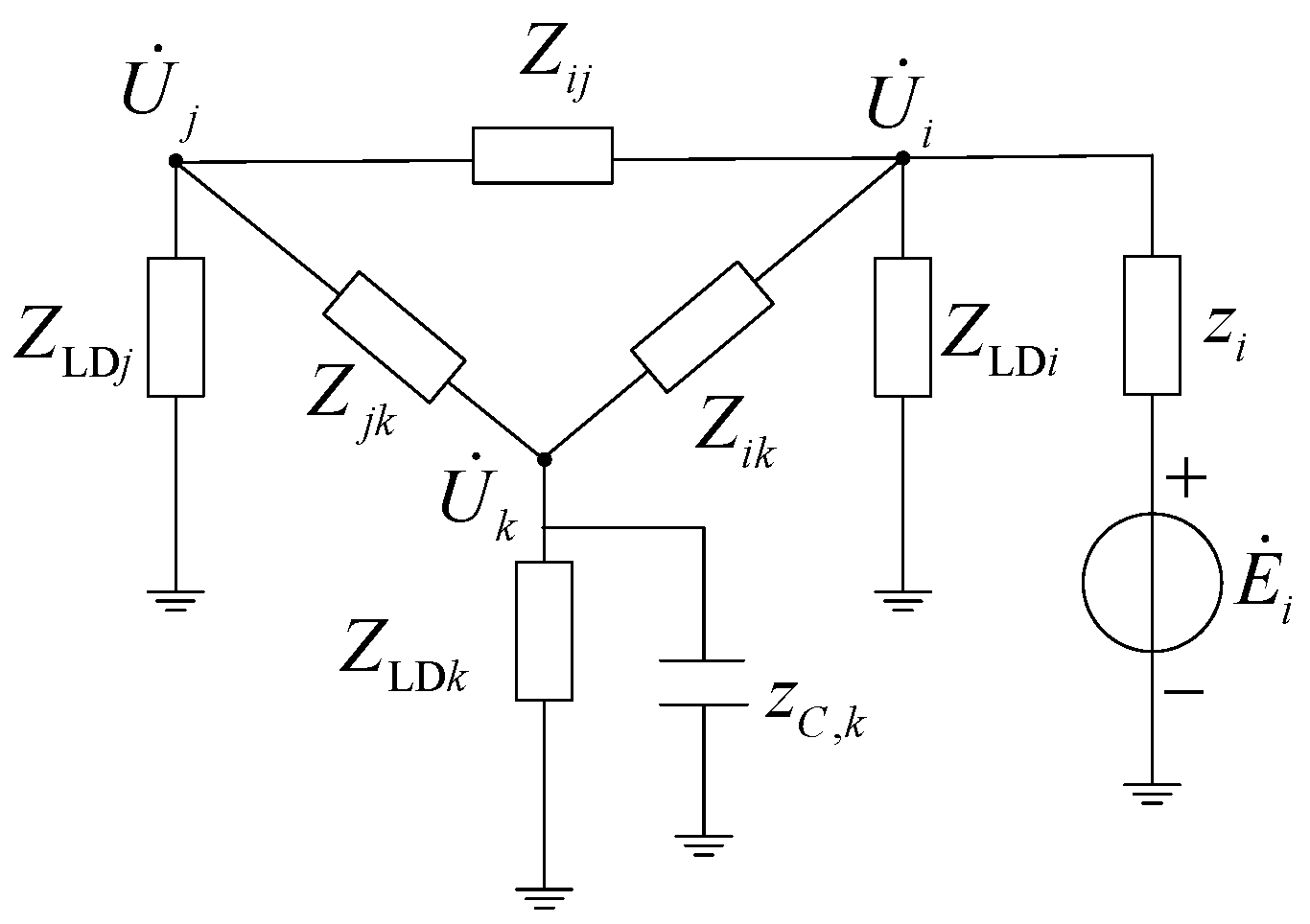
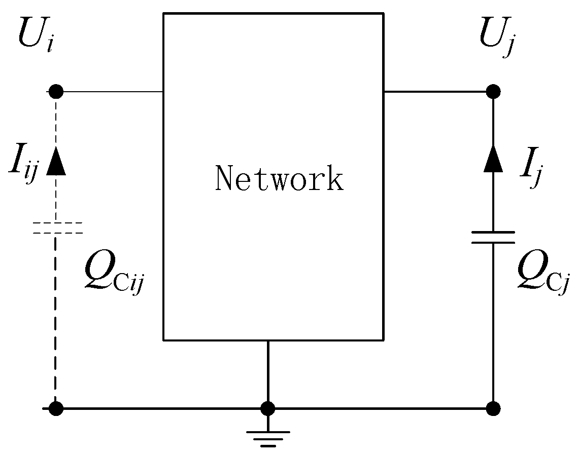
2. Short-Circuit Ratio of the Multi-Infeed DC System

For single-infeed AC/DC systems, SCR or ESCR are widely used to measure the strength of the AC system in maintaining the voltage stability. The SCR is defined as the ratio of the short-circuit capacity at rectifier/inverter station k to the DC rated terminal power PdN,k [5]:
K S C R , k = S c , k P d N , k
Since most HVDC transmission projects in China adopt line commutated converter based HVDC (LCC-HVDC), the inverter stations usually consume a lot of reactive power during operation. Thus, the inverter stations are usually installed with a large capacity of shunt capacitor compensations. The capacitive compensator will increase the short-circuit impedance of the DC-infeed system, thereby reducing its short-circuit capacity. Therefore, it is necessary to take into account the influence of the shunt capacitor compensations installed at the inverter station [21]. The ESCR is defined in [5] as:
K E S C R , k = S c , k Q C , k P d N , k
In the multi-infeed AC/DC system, since the conventional single-infeed SCR does not take the interaction between different DC transmissions into account, the evaluation results tend to be too optimistic [4]. In order to accurately evaluate the stability of the multi-infeed AC/DC system, the International Council on Large Electric Systems (in French: Conseil International des Grands Réseaux Électriques, abbreviated CIGRÉ) Direct Current (DC) Working Group proposed a multi-infeed effective short-circuit ratio (MESCR) in 2007 [12].
The calculation of MESCR integrates the interaction between the DC inverter buses through defining a multi-infeed interaction factor (MIIF) to quantify the interaction between DC inverter buses [12]. MIIF is designed to reflect the electrical coupling between the DC inverters, and it is defined as:
M I I F i j = Δ U i j Δ U j j = | Z j i Z j j |
Based on the ESCR in single infeed systems, after taking the interaction between multiple DC inverter buses into account, the MESCR of inverter bus j is defined as:
K M E S C R , j = S c , j Q C , j P d N , j + i = 1 , i j K M I I F i j P d N , i

3. Limitations of the Existing Multi-Infeed Short Circuit Ratio

When adopting the MESCR defined in [12] to evaluate the strength of the Eastern China Grid, the MESCR values are much higher than the threshold for strong systems recommended in [12]. However, the system collapses in several N-1 contingencies during the N-1 contingency analysis. Namely, the simulation results indicate that the Eastern China Grid is in fact not a strong system. Through empirical studies, we found that the MESCR is insensitive to variations of capacitor compensations in the Eastern China Grid. According to Equation (4), for a given DC rectifier/inverter bus, the capacitor compensations could only affect the MESCR through influencing the short-circuit capacity Sc,j and the multi-infeed interaction factor MIIFij. Therefore, the capacitor compensations’ influence on the short-circuit capacity and multi-infeed interaction factor will be theoretically analyzed in detail in this section.
At present, most reactive power compensation facilities installed in power systems are shunt capacitors [22]. The reactive power QC supplied by a shunt capacitor is proportional to the square of the bus voltage V, namely QC = V2/XC. When the bus voltage drops, the reactive power provided by the capacitor will also decrease, which will cause a further decrease of the bus voltage or even lead to a voltage collapse. Therefore, the shunt capacitor with poor reactive power regulation performance may have a negative influence on the transient voltage stability of power systems [23]. Considering the potential negative influence of capacitor compensations on voltage stability, reference [5] suggests the consideration of the shunt capacitors when calculating the SCR.

3.1. The Capacitor Compensation’s Influence on the Short-Circuit Capacity

The short circuit capacity is defined as the rated voltage of the short circuit bus times the short circuit current. The short circuit current can be calculated by dividing the electric potential of the voltage source i with the transfer impedance from voltage sources to the short-circuit point [24,25]. Therefore, for the demonstration system shown in Figure 1, the short-circuit capacity at bus j can be calculated as:
S C , j = U N , j | I ˙ S C , j | = 1 | I ˙ S C , j | = | E ˙ i z ˜ j i |
The transfer impedance can be easily calculated with the nodal impedance matrix, and can be expressed as follows:
z ˜ j i = Z j j Z j i z i
When a capacitor with capacity QC,k is installed at bus k, the self-impedance of bus j and the mutual impedance between j and i become:
z C , k = j U k 2 Q C , k = j 1 Q C , k
Z j j = Z j j Z j k 2 Z k k + z C , k
Z j i = Z j i Z j k Z k i Z k k + z C , k
Substituting Equations (8) and (9) into Equation (6), the transfer impedance between bus j and i after installing a capacitor at bus k can be expressed as:
z ˜ j i = Z k k Z j i + Z j i z C , k Z j k Z k i Z j j Z k k + Z j j z C , k Z j k 2 z i
After installing the shunt capacitor at bus k, the deviation of the short-circuit capacity at bus j can be expressed as:
Δ S C , j = | I ˙ S C , j | | I ˙ S C , j | | I ˙ S C , j I ˙ S C , j |
Substituting Equations (5), (6), and (10) into Equation (11), we have:
I ˙ S C , j I ˙ S C , j = E ˙ i Z j k ( Z j i Z j k Z k i Z j j ) Z j j [ Z j j ( Z k k + z C , k ) Z j k 2 ]
Thus, the capacitor compensation’s influence on the short circuit capacity can be expressed as:
Δ S C , j | E ˙ i Z j k ( Z j i Z j k Z k i Z j j ) Z j j [ Z j j Z k k Z j k 2 j Z j j / Q C , k ] |
From Equation (13), it can be seen that when the compensation capacity QC,k is relatively small or comparable to the self-impedance of bus j, the short circuit capacity will be significantly affected. However, when QC,k is much larger than the self-impedance of bus j, Δ S C , j will be saturated and almost retain the same value no matter how large QC,k is. The variation of Δ S C , 33 along with the increasing QC,20 in a standard New England 10-machine-39-bus system given in [26] is illustrated in Figure 2. As analyzed above, it can be concluded that the short circuit capacity would be saturated and incapable of reflecting the influence of the capacitor compensations when the compensation is relatively large compared with the self-impedance of the installation bus.

3.2. The Capacitor Compensation’s Influence on the Multi-Infeed Interaction Factor

Following the same routine of the analysis in Section 3.1, after a shunt capacitor with a capacity of QC,k is installed at bus k, the self-impedance and the transfer impedance of the DC inverter bus i and j will be:
Z i i = Z i i Z k i 2 Z k k + z C , k
Z j j = Z j j Z k j 2 Z k k + z C , k
Z j i = Z j i Z k j Z k i Z k k + z C , k
After the installation of the shunt capacitor, the MIIF of the inverter station j to the inverter station i will become:
M I I F i j = | Z j i Z j j | = Z j i ( Z k k + z C , k ) Z k j Z k i Z j j ( Z k k + z C , k ) Z k j 2
Before and after the installation of the shunt capacitor, the deviation of MIIF from the inverter station j to the inverter station i will be:
Δ M I I F i j = M I I F i j M I I F i j = Z j i ( Z k k + z C , k ) Z k j Z k i Z j j ( Z k k + z C , k ) Z k j 2 Z j i Z j j = Z k j ( Z j j Z k i Z j i Z k j ) Z j j [ Z j j Z k k j Z j j Q C , k Z k j 2 ]
As can be seen from Equation (18), the denominator of Δ M I I F i j is the same as in Equation (13), so Δ M I I F i j will have the same pattern as Δ S C , j . When QC,k is significantly greater than the self-impedance of the short circuit bus j, Δ M I I F i j will also saturate and retain the same value, no matter how large QC,k is. Therefore, when the capacitor compensations are concentratively installed in the system, the influence of the capacitor compensations on the multi-infeed interaction factor can hardly be observed.

3.3. The Capacitor Compensation’s Influence on the Multi-Infeed Effective Short Circuit Ratio

According to Equation (4), the MESCR could only be affected by the capacitor compensations though changing the short circuit capacity SC,i and the multi-infeed interaction factor MIIFji. However, with the theoretical analysis carried out above, if the capacity of the capacitor installed at bus k is sufficiently large, the deviations in both the short circuit capacity and the multi-infeed interaction factor can hardly be observed. This indicates that the short circuit capacity and MIIF both will be saturated in power systems with large amounts of capacitors concentratively installed. Therefore, the existing MESCR almost remains unchanged after installing a large capacitor in the system. In other words, when the capacitor compensation in the system is relatively concentrated, the existing MESCR will not be able to observably reflect the negative influence of the shunt capacitors on the voltage stability of the AC/DC system.

4. Improved MESCR Considering All Capacitor Compensations

To address the limitations of the conventional MESCR that saturates and cannot correctly indicate the system strength in power systems with massive shunt capacitors installed, this paper proposes an improved multi-infeed effective short circuit ratio (IMESCR) that takes the influence of shunt capacitor compensation into consideration so as to indicate the strength of power systems with large amount of reactive power compensations installed more accurately.
In order to consider the influence of all capacitor compensations in a multi-DC-infeed system during calculation of the MESCR, this paper proposes a method to convert the reactive power compensations installed at any bus in the system to a virtual capacitor installed at the DC rectifier/inverter bus. Assuming bus i is the DC rectifier/inverter bus, and bus j installs a capacitor with the capacity of QC,j, the simplified system is illustrated in Figure 3.
The method of converting the shunt capacitor QCj on bus j to a virtual compensation QCij on bus i is theoretically formulated as follows:
When injecting current Ij into bus j, the resulting voltage on bus i will be:
U i j = I j Z i j = ( I j Z i j Z i i ) Z i i
Meanwhile, Uij can also be expressed as the voltage on bus i when the current Iij is injected into bus i:
U i j = I i j Z i i
By substituting Equation (20) into Equation (19), the current Ij injected into bus j can be converted to the current Iij injected on bus i:
I i j = I j Z i j Z i i
With Equation (21), the reactive current provided by the shunt capacitor at bus j can be converted to the reactive current at bus i, therefore the compensation capacity QC,j on bus j can be converted to a virtual capacitor on bus i, and the capacity QCij of the converted virtual capacitor on bus i converted from bus j can be calculated as:
Q C i j = U i I i j * = U j I j * | Z i j Z i i | = Q C , j | Z i j Z i i |
In the equation, Zij/Zii is defined as the reactive power conversion factor from bus j to bus i, and it reflects the electrical coupling between these two buses.
With Equation (22), all reactive compensations in the system can be converted to the DC rectifier/inverter bus. Therefore, based on the definition of the ESCR, the IMESCR could be calculated as:
K I M E S C R , i = S c i j = 1 N Q C i j P d N , i + j = 1 , j i k M I I F j i P d N , j = S c i Q C , i + j = 1 , j i N Z i j Z i i Q C , j ) P d N , i + j = 1 , j i K M I I F j i P d N , j
Since the IMESCR proposed in this paper followed the same routine of conventional MESCR calculation, and only integrates the negative influences of the shunt capacitors, the IMESCR should keep using the same standard of MESCR for judging the strength of multi-infeed AC/DC power system [11]. So the recommended threshold for determining the system strength is as follows: (1) for strong systems, IMESCR > 2.5; (2) for weak systems, 1.5 < IMESCR ≤ 2.5; (3) for extremely weak systems, IMESCR ≤ 1.5.

5. Case Studies

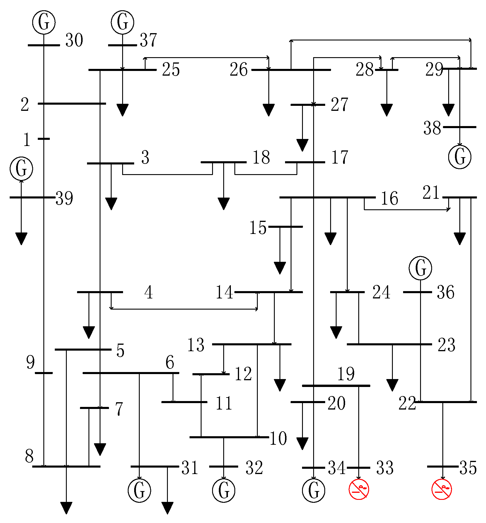
5.1. Case I: New England 10-Machine-39-Bus System

In order to demonstrate the limitations of the conventional MESCR and verify the accuracy of the IMESCR proposed in this paper, a modified New England 39-bus system is adopted for the case study. Based on the New England 39-bus system modified in [27,28] and the initiative of designing cases near the stability boundary, here we replace the generators on bus 33 and 35 with two DC inverter stations, the active power injected by the DC transmission line is the same as that generated by the generators being replaced, and the capacity of the capacitors installed at the inverter buses is half of the active power injected by the DC transmission. After the modification, the system becomes a 2-DC infeed system, and the modified New England system is illustrated in Figure 4. Besides the modifications, all other parameters are kept the same as the standard New England 39-bus system given in [26]. The simulation is carried out on the PSD-BPA platform, and the quasi-steady model of the DC transmission line is adopted to simulate the DC transients. By using the short circuit current calculation program (named PSD-SCCP) provided in the PSD-BPA, the short-circuit current at the DC inverter can be easily obtained.

5.1.1. Case Designs for the New England Test System

To demonstrate that the conventional MESCR is insensitive to shunt capacitor compensations installed in the system, and to verify that the IMESCR can correctly reflect the influences of the capacitor capacities and installed locations, here we design two series of cases to investigate the influences of different compensation capacities and compensated locations separately. The designed cases are listed in Table 1. In the compensation capacity cases, the capacity of the capacitor compensation installed at bus 22 is gradually increased. In the compensation location cases, the installation location of a 200 MVar capacitor is gradually moved closer to the inverter buses 33 and 35.

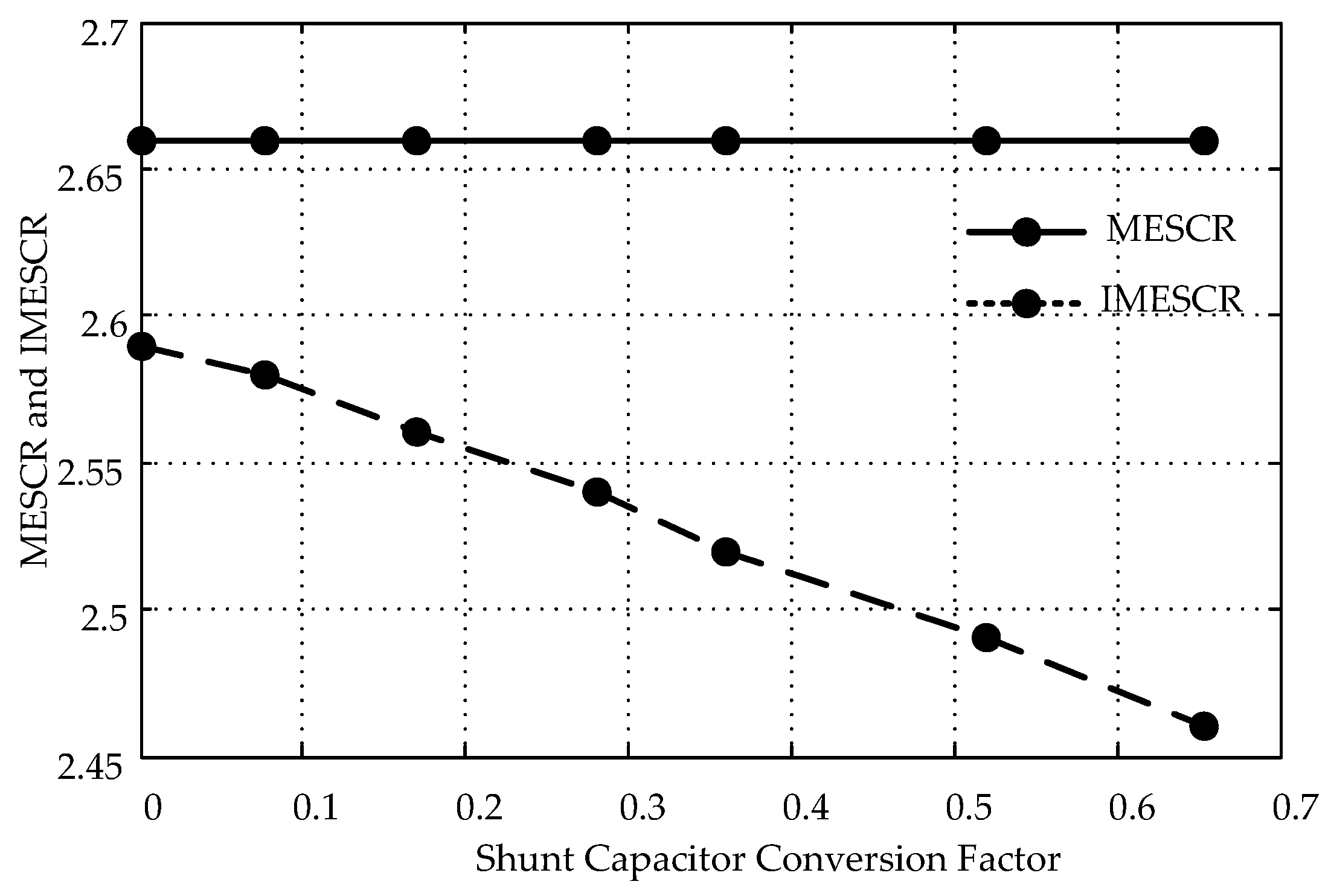
5.1.2. Compensation Capacity’s Influence on MESCR and IMESCR

In order to analyze the influence of compensation capacities on the MESCR, we calculated the MESCR, IMESCR, as well as the results of the N-1 contingency analysis for all compensation capacity cases designed in Section 5.1.1, and the results are listed in Table 2.
The MESCR and IMESCR of bus 33 and 35 for all compensation capacity cases are plotted in Figure 5. It can be easily seen from Table 2 and Figure 5 that,
(a)
After increasing the compensation capacity on bus 22, the number of system collapses in the N-1 contingency analysis increased gradually, which indicates that the strength of the system is decreasing with the increasing compensation capacity;
(b)
When increasing the capacity of the capacitor compensation, the MESCR and MIIF remain almost unchanged. Even when the shunt capacity reached 250 MVar, the MIIF only increased by 2.3%, and the MESCR only decreased by less than 0.4%. These results are consistent with the saturation phenomenon we found in Section 3;
(c)
The proposed IMESCR decreases with the increase of the capacity of the shunt capacitors, which is in accordance with the trend of the system strength reflected by the results of the N-1 contingency analysis, and after the IMESCR of bus 35 becomes lower than the threshold of a strong system (2.5), the system starts to collapse after the N-1 contingency.

5.1.3. The Compensation Location’s Influence on MESCR and IMESCR

After installing the 200 Mvar shunt capacitor at buses with different electrical distances from the DC inverter buses 33 and 35, the observed system collapses in the N-1 contingency analysis and the calculated MESCR and IMESCR are presented in Table 3. The conversion factors listed in the table are the ratios of the mutual-impedance between the compensation bus and the DC inverter bus 35 to the self-impedance of the DC inverter bus 35. Higher conversion factors denote closer electrical distances between the compensation bus and the DC inverter bus.
By plotting the MESCR and IMESCR of the DC inverter bus 35 of all compensation bus cases in Figure 6, it can be easily seen that:
(a)
When the same capacitor is installed closer to the DC inverter bus in terms of electrical distance, the system will be more vulnerable to N-1 contingencies. Which means that the negative influence of the capacitor compensations on the stability of the AC/DC power system is related to the distance between the compensation bus and the DC inverter bus;
(b)
Along with moving the capacitor closer to the inverter bus, the MESCR and MIIF are only slightly changed, which is consistent with the theoretical analysis and indicates that the MESCR cannot reflect the variations of system stability along with different capacitor installation buses;
(c)
After the capacitor is installed closer to the DC inverter bus, the IMESCR obviously decreases, which is consistent with the decreasing trend of the system strength, thus verifying that the proposed IMESCR can correctly reflect the influences of different reactive power compensation buses on the system strength.

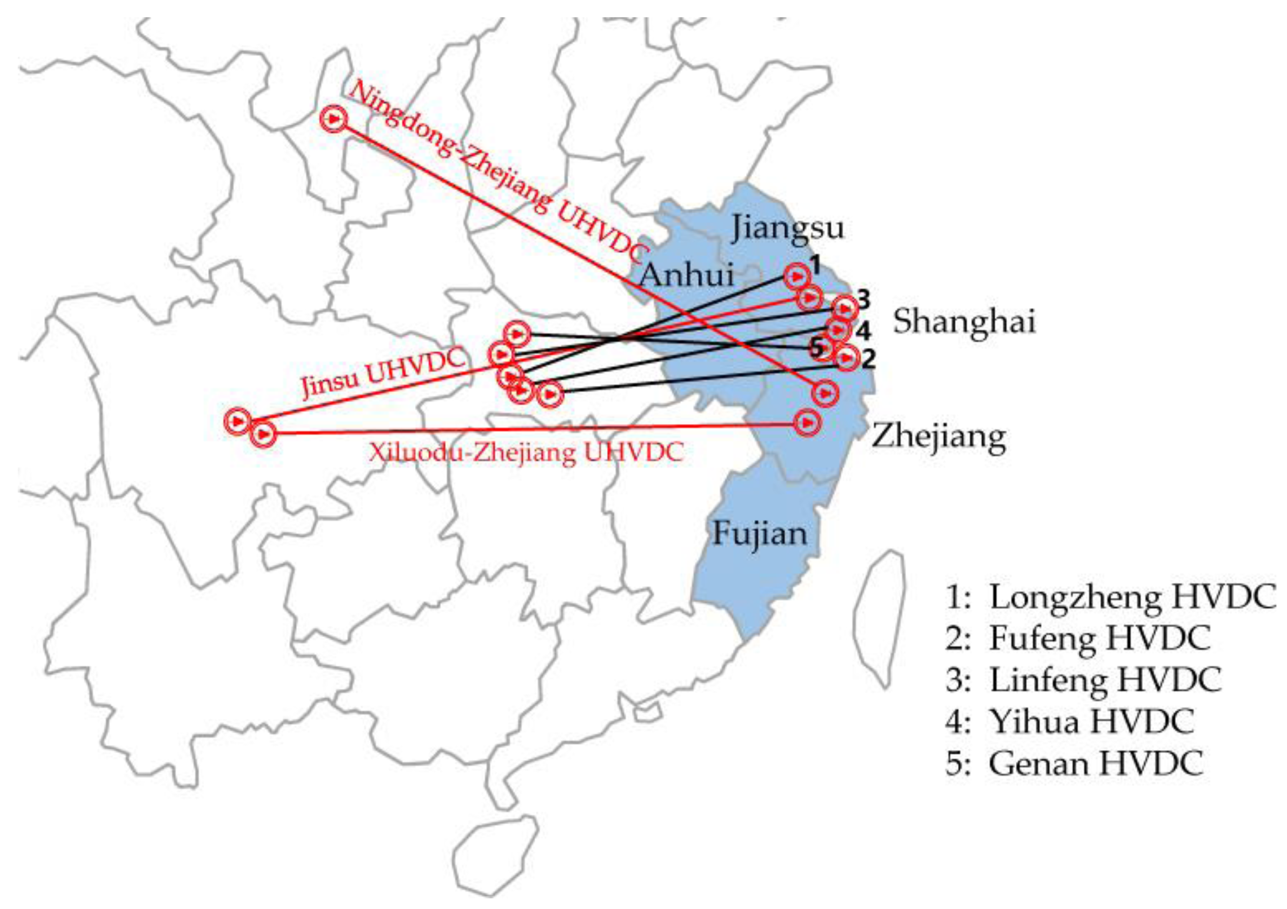
5.2. Case II: Eastern China Regional Power Grid

To verify the accuracy of the proposed IMESCR in practical power systems, this section designed a few cases based on the summer operation mode of the Eastern China Grid to compare the MESCR and IMESCR.

5.2.1. Brief Introduction of the Eastern China Grid

The Eastern China Grid is one of the largest demand centers in China which consists of the Shanghai City and four provinces of Jiangsu, Zhejiang, Anhui, and Fujian. By the end of 2016, it had 4357 buses with voltage levels higher than 220 kV and 5379 transmission lines. The number of generators installed in the Eastern China Grid reached 521 at the same year. Estimated by the State Grid Corporation of China, the peak load in the Eastern China Grid in 2016 reached 246.9 GW. Besides the huge electricity demand and large generation capacity, as illustrated in Figure 7, the Eastern China Grid had three UHVDC and five HVDC transmission lines fed into the system in 2016, making it the largest multi-infeed system in China. Here we adopt the summer operation mode of the Eastern China Grid in 2016 to verify the feasibility of the proposed IMESCR, and the power transmitted on all DC transmission lines in the summer operation mode are listed in Table 4. The simulation is also carried out on the PSD-BPA platform.

5.2.2. Cases Designs

In order to verify the accuracy of the proposed IMESCR in evaluating the strength of practical systems, this paper designs six cases based on the 2016 summer operation mode of the Eastern China Grid. All cases are designed with the following procedure: Firstly, keeping the power transmitted by DC transmission lines unchanged, we shut down the generators near the DC inverter station to reduce the voltage support near the inverter bus. Secondly, we start generators at buses far away from the inverter bus to keep the balance of active power. Thirdly, we install a certain number of shunt capacitors near the DC inverter bus to maintain the system voltage.
Following the same procedures, six cases are designed and listed in Table 5. In the six cases, case 3 and case 4 have the same generators shut down near the inverter station, and only differ in the capacity of the capacitor compensations installed in the system. Since the N-1 contingency analysis can directly reflect the strength of a system, here we adopt the number of system collapses in the N-1 contingency analysis to denote the actual system strength of each case, and the results of the N-1 contingency analysis for all cases are also listed in Table 5. The N-1 contingency set consisted of the permanent three-phase short-circuit on both sides of all 500 kV and 1000 kV lines in the Eastern China Grid. After the permanent three-phase short-circuit occurs, the near-end breaker switches off after 0.09 s and the far-end breaker switches off after 0.1 s. The generation capacity shuts down near the inverter bus and the reactive power compensation listed in the table are the relative deviations compared with case 1.
As can be seen from Table 5, after gradually shutting down generators near the DC inverter bus, the number of system collapses in the N-1 contingency analysis keeps increasing, which means the strength of the system is reducing case by case.

5.2.3. MESCR and IMESCR Comparison
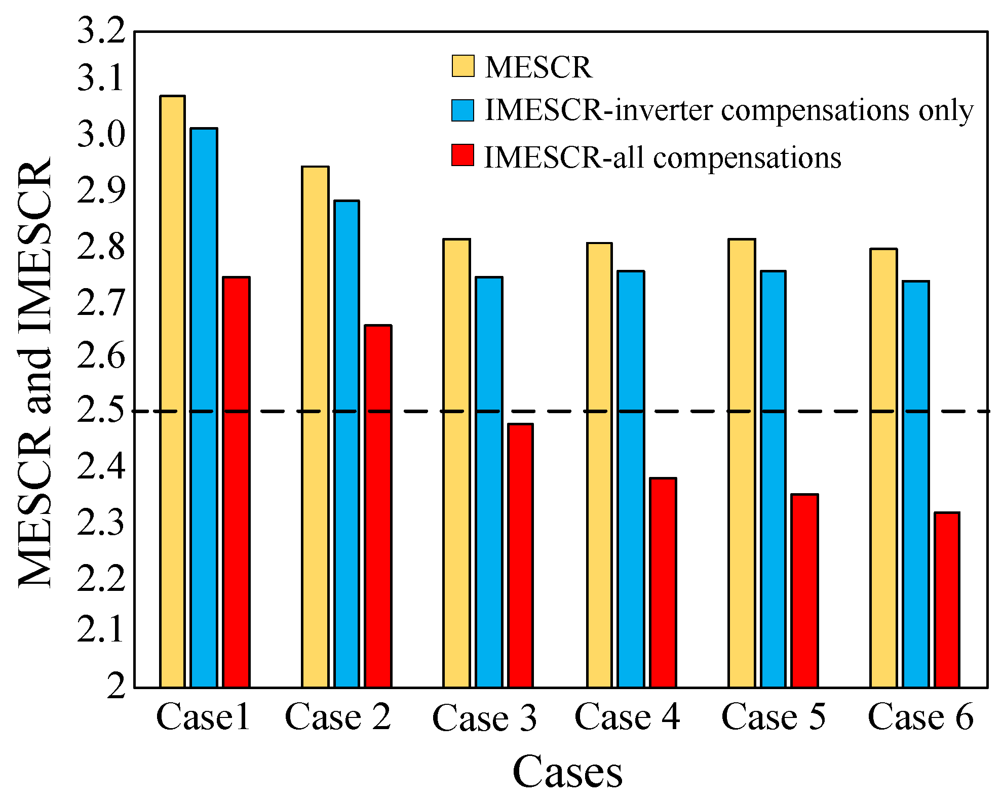
Calculating the MESCR and IMESCR of the inverter bus of the Xiluodu-Zhejiang UHVDC in all cases, the results are listed in Table 6.
The calculated MESCR and IMESCR of all cases are also illustrated in Figure 8. As can be seen from Table 6 and Figure 8, the following conclusions can be drawn:
(a)
The short-circuit capacity of the inverter bus will be reduced if nearby generators are shut down, thus leading to the decrease in MESCR and IMESCR;
(b)
The MESCR of all cases are obviously higher than the threshold for strong systems. However, in cases 4–6, the results of the N-1 contingency analysis indicate that these cases all have poor stability margins;
(c)
The MESCR of case 3 and case 4 are very close, which is in accordance with the conclusion drawn in Section 3: if a large amount of capacitors are already concentratively installed in the system, the MESCR will retain the same value regardless of how many capacitor compensations are installed;
(d)
The IMESCR with only the compensations installed at the inverter buses considered in case 5 and case 6 is still much larger than the threshold for strong systems, but actually these two cases have 15 and 17 collapses in the N-1 contingency analysis, which means that these cases in fact are not strong enough. Therefore, considering only the capacitor compensations installed at the inverter buses is not enough for an accurate stability evaluation;
(e)
After taking all shunt compensations in the system into consideration, the value of IMESCR is more than 15% less than the traditional MESCR, and it decreases much faster than the MESCR along with the increase of the compensation capacity. Especially for cases with a large amount of shunt capacitors installed, for example case 5 and case 6, their IMESCR becomes lower than the threshold for a weak system, which is in good accordance with the N-1 contingency analysis. Therefore, the results of the studied cases prove the accuracy of the proposed IMESCR in evaluating the strength of a practical power system.
Through the comparative study carried out in the Eastern China Grid, it can be further confirmed that MESCR will become saturated if a large amount of capacitor compensations are concentratively installed in the power system. For systems with massive installed capacitor compensations, the proposed IMESCR is in good accordance with the system strength indicated by the N-1 contingency analysis, thus verifying the proposed IMESCR as a promising index for evaluating the strength of massive installed capacitor compensation systems.

6. Conclusions

This paper analyzed the limitation of conventional MESCR in evaluating the strength of power systems with massive installed capacitor compensation, and proposed an improved multi-infeed effective short-circuit ratio which can take into consideration the influences of capacitor compensations installed throughout the system. The case studies carried out based on the New England 10-machine-39-bus system and the Eastern China Grid verified the accuracy of the proposed IMESCR in evaluating the stability of power systems with large amounts of reactive power compensations. The main conclusions of this paper are as follows:
(a)
Installing a large amount of shunt capacitor compensations in the AC system with infeed DC transmission lines will reduce the stability of the system. The greater the compensation capacity is and the closer the compensation bus is to the DC rectifier/inverter station, the greater the decrease in system strength will be.
(b)
The saturation of MESCR in large amount capacitor concentratively installed systems was theoretically proved, and the saturation phenomenon indicates that the conventional MESCR is incapable of reflecting the influence of shunt capacitor compensations on the system strength, as well as the influence of various compensation locations.
(c)
Through converting all the capacitor compensations installed in the system to virtual capacitors at the inverter bus, the proposed IMESCR could overcome MESCR’s limitation of insensitive to compensation capacity and compensation locations in heavily compensated systems, and thus could evaluate the strength of massive capacitor compensation installed systems more accurately then the MESCR.
(d)
The difference between the proposed IMESCR and MESCR will be more significant if a larger amount of capacitor compensations are installed in the system.
(e)
The proposed IMESCR could be a potential index for DC transmission planning in power systems installed with large amount of capacitor compensations.

Acknowledgments

This work is supported by the National Key Research and Development Program of China (2016YFB0900805, 2016YFB0900800).

Author Contributions

S.L., W.Y., J.W., and Q.L. designed the improved multi-infeed effective short-circuit ratio, S.L. and X.A. performed the experiments; Q.L. and Y.J. analyzed the data; J.Z. and J.T. provides the power grid data, simulation platform, and instructions for carrying out the simulation; All authors discussed the results and contributed to writing the paper.

Conflicts of Interest

The authors declare no conflict of interest.

Abbreviations

HVDCHigh Voltage Direct Current
UHVDCUltra-High Voltage Direct Current
SCRShort Circuit Ratio
MSCRMulti-infeed Short Circuit Ratio
MESCRMulti-infeed Effective Short Circuit Ratio
IMESCRImproved Multi-infeed Effective Short Circuit Ratio
MIIFMulti-Infeed Interaction Factor
LCCLine Commutated Converters

Nomenclature

Sc,iShort-circuit capacity of the DC rectifier/inverter bus i
PdN,iRated DC terminal power on the rectifier/inverter bus i
K S C R , i , K E S C R , i Short circuit ratio and effective short circuit ratio of bus i
Q C , i Capacity of shunt capacitors installed at bus i
Δ U j i , Δ U i i Voltage deviation at bus j and i caused by reactive perturbation at bus i
K MESCR i Multi-infeed short circuit ratio of bus i
E ˙ i Electric potential of voltage source i
z ˜ j i , z ˜ j i Transfer impedance from bus i to bus j before and after a shunt capacitor is installed at bus k
Z i j , Z i j Mutual impedance between bus j and i before and after a shunt capacitor is installed at bus k
Z j j , Z j j Self-impedance of bus j before and after a shunt capacitor is installed at bus k
z i Internal impedance of voltage source i
z C , k Impedance of the shunt capacitor installed at bus k
I ˙ S C , j , I ˙ S C , j Short-circuit current at bus j before and after a capacitor is installed at bus k
Δ S C , j Deviation of short-circuit capacity of bus j
M I I F i j , M I I F i j Multi-infeed interaction factor between bus i and j before and after a shunt capacitor is installed at bus k
I j Current injected into bus j
U i j Voltage on bus i when current Ij is injected into bus j
I i j Current injected into bus i to make the voltage on bus i equal to U i j
U i , U N , i Actual voltage and rated voltage of bus i
Q C i j Capacity of the virtual capacitor on bus i converted from real capacitor installed at bus j
NNumber of buses in the system
KNumber of DC transmission lines fed into the system

References

  1. Karawita, C.; Annakkage, U.D. Multi-infeed HVDC interaction studies using small-signal stability assessment. IEEE Trans. Power Deliv. 2009, 24, 910–918. [Google Scholar] [CrossRef]
  2. Long, W.; Nilsson, S. HVDC transmission: Yesterday and today. IEEE Power Energy Mag. 2007, 5, 22–31. [Google Scholar] [CrossRef]
  3. Yao, W.; Jiang, L.; Wen, J.Y.; Wu, Q.H.; Cheng, S.J. Wide-area damping controller for power system inter-area oscillations: A networked predictive control approach. IEEE Trans. Control Syst. Technol. 2015, 23, 27–36. [Google Scholar] [CrossRef]
  4. Sao, Y.; Tang, Y.; Guo, X.J.; Xiao, Q.Y. Transient voltage stability analysis of East China receiving-end power grid with multi-infeed HVDC transmission lines. Power Syst. Technol. 2011, 35, 50–55. (In Chinese) [Google Scholar]
  5. IEEE Guide for Planning DC Links Terminating at AC Locations Having Low Short-Circuit Capacities; IEEE Standard 1204-1997; The Institute of Electrical and Electronics Engineers: New York, NY, USA, 1997.
  6. Rahimi, E.; Gole, A.M.; Davies, J.B. Analysis of multi-infeed HVDC systems with inverter and rectifier connected to the same AC network. In Proceedings of the IET International Conference on AC and DC Power Transmission, London, UK, 19–21 October 2010.
  7. Chen, X.; Gole, A.M.; Han, M. Analysis of mixed inverter/rectifier multi-infeed HVDC systems. IEEE Trans. Power Deliv. 2012, 27, 1565–1573. [Google Scholar] [CrossRef]
  8. Lee, D.; Andersson, G. An Equivalent Single-Infeed Model of Multi-Infeed HVDC Systems for Voltage and Power Stability Analysis. IEEE Trans. Power Deliv. 2016, 31, 303–312. [Google Scholar] [CrossRef]
  9. Rahimi, E.; Gole, A.M.; Davies, J.B.; Fernando, I.T.; Kent, K.L. Commutation failures analysis in multi-infeed HVDC systems. IEEE Trans. Power Deliv. 2011, 26, 378–384. [Google Scholar] [CrossRef]
  10. Denis, L.H.A.; Andersson, G. Voltage stability analysis of multi-infeed HVDC systems. IEEE Trans. Power Deliv. 1997, 12, 1427–1437. [Google Scholar]
  11. Lin, W.F.; Tang, Y.; Bu, G.Q. Definition and application of short circuit ratio for multi-infeed AC/DC power systems. Proc. CSEE 2008, 28, 1–8. (In Chinese) [Google Scholar]
  12. CIGRÉ Working Group B4.41. Systems with Multiple DC Infeed. Available online: http://b4.cigre.org/Publications/Technical-Brochures/TB-364-2008-WG-B4.41-Systems-with-multiple-DC-Infeed (accessed on 18 March 2017).
  13. Lee, D.; Andersson, G. Analysis of voltage and power interactions in multi-Infeed HVDC systems. IEEE Trans. Power Deliv. 2013, 28, 816–824. [Google Scholar]
  14. Chen, X.W.; Guan, L. Research on limitation of the multi-infeed short circuit ratio. In Proceedings of the 2016 IEEE PES Asia-Pacific Power and Energy Engineering Conference (APPEEC), Xi’an, China, 25–28 October 2016; pp. 712–715.
  15. Lin, W.F.; Tang, Y. Analysis of influencing factors of short circuit ratio of multi-infeed AC/DC power systems. In Proceedings of the 2015 5th International Conference on Electric Utility Deregulation and Restructuring and Power Technologies (DRPT), Changsha, China, 26–29 November 2015; pp. 732–734.
  16. Kang, Z.; Yang, D.; Liu, Y. A new definition of multi-infeed short circuit ratio considering control modes of DC system. In Proceedings of the 2015 International Power, Electronics and Materials Engineering Conference, Dalian, China, 16–17 May 2015; pp. 551–556.
  17. Liu, D.; Shi, D.; Li, Y. A new definition of short-circuit ratio for multi-converter HVDC systems. J. Electr. Eng. Technol. 2015, 10, 1958–1968. [Google Scholar] [CrossRef]
  18. Zhang, F.; Xin, H.; Wang, Z.; Gan, D.; Xu, Q.; Dai, P.; Liu, F. A Generalized Short Circuit Ratio for Multi-Infeed LCC-HVDC System. arXiv 2017. [Google Scholar]
  19. Hwang, S.; Lee, J.; Jang, G. HVDC-System-Interaction Assessment through Line-Flow Change-Distribution Factor and Transient-Stability Analysis at Planning Stage. Energies 2016, 9, 1068. [Google Scholar] [CrossRef]
  20. Li, E.C.; Chu, X.D.; Yang, M.H. Static voltage stability analysis for multi-infeed HVDC systems based on multivariate regression. In Proceedings of the 2016 IEEE PES Asia-Pacific Power and Energy Engineering Conference (APPEEC), Xi’an, China, 25–28 October 2016; pp. 130–134.
  21. IEEE Guide for Application of Shunt Power Capacitors; IEEE Standard 1036™-2010; The Institute of Electrical and Electronics Engineers: New York, NY, USA, 2010.
  22. Kundur, P. Power System Stability and Control; McGraw-Hill: New York, NY, USA, 1994. [Google Scholar]
  23. Yuan, X.H.; Dai, X.B. Energy-saving analysis for power system reactive power compensation. Adv. Mater. Res. 2013, 608–609, 1151–1155. [Google Scholar] [CrossRef]
  24. He, Y.Z.; Wen, Z.Y. Power System Analysis; Huazhong University of Science and Technology Press: Wuhan, China, 2002. (In Chinese) [Google Scholar]
  25. Bird, J. Electrical Circuit Theory and Technology, 5th ed.; Routledge: Abingdon, UK, 2014. [Google Scholar]
  26. Pai, M.A. Energy Function Analysis for Power System Stability; Kluwer: Boston, MA, USA, 1989. [Google Scholar]
  27. Bueno, P.G.; Hernández, J.C.; Ruiz-Rodriguez, F.J. Stability assessment for transmission systems with large utility-scale photovoltaic units. IET Renew. Power Gener. 2016, 10, 584–597. [Google Scholar] [CrossRef]
  28. Yao, W.; Jiang, L.; Wen, J.Y.; Wu, Q.H.; Cheng, S.J. Wide-area damping controller of FACTS devices for inter-area oscillations considering communication time delays. IEEE Trans. Power Syst. 2014, 29, 318–329. [Google Scholar] [CrossRef]
Figure 1. Simplified Alternating Current (AC) system.
Energies 10 00396 g001
Figure 2. Relationship between the short-circuit capacity deviation and shunt compensation capacity.
Energies 10 00396 g002
Figure 3. Schematic diagram of converting the shunt capacitor’s capacity from bus j to bus i.
Energies 10 00396 g003
Figure 4. Two-infeed AC/DC New England test system.
Energies 10 00396 g004
Figure 5. MESCR and IMESCR of two DC inverter buses under different compensation capacities.
Energies 10 00396 g005
Figure 6. MESCR and IMESCR of the DC inverter bus 35 under different capacitor installation locations.
Energies 10 00396 g006
Figure 7. Schematic of the Eastern China Grid.
Energies 10 00396 g007
Figure 8. Comparison between the MESCR and IMESCR in the Eastern China Grid.
Energies 10 00396 g008
Table 1. Two case series designed for the New England 39-bus system.
Case SeriesControlled VariableCase 1Case 2Case 3Case 4Case 5Case 6Case 7
Compensation capacity casesCapacitor capacity installed at bus 22050100150200250×
Compensation bus casesCapacitor installation bus-Bus 1Bus 3Bus 15Bus 24Bus 23Bus 22
Table 2. Multi-infeed effective short circuit ratio and improved multi-infeed effective short circuit ratio of the DC inverter buses under different shunt capacitor capacities.
Capacitor Capacity/MVarNumber of System CollapsesMulti-Infeed Interaction Factor between Bus 33 and 35Bus 33Bus 35
MESCRIMESCRMESCRIMESCR
000.2582.712.622.672.59
5000.2582.712.602.672.55
10000.2592.712.582.672.51
15010.2602.712.562.662.48
20010.2622.702.542.662.46
25020.2642.702.532.662.42
Table 3. MESCR and IMESCR of the DC inverter bus-35 under different compensation buses.
Compensation BusConversion Factor from Compensation Bus to Inverter Bus 35Number of System CollapsesMIIF between Bus 33 and 35MESCRIMESCR
None-00.2582.662.59
Bus-10.07700.2582.662.58
Bus-30.17000.2602.662.56
Bus-150.28100.2632.662.54
Bus-240.36000.2642.662.52
Bus-230.51910.2622.662.49
Bus-220.65310.2622.662.46
Table 4. High voltage DC and ultra-high voltage DC transmission lines in the Eastern China Grid.
DC TransmissionVoltage Level/kVTransmitted Power/MWInverter Bus
Longzheng±5003000Changzhou, Jiangsu
Jinsu±8007200Suzhou, Jiangsu
Linfeng±5003000Shanghai
Yihua±5003000Shanghai
Genan±5001160Shanghai
Fufeng±5006400Shanghai
Xiluodu-Zhejiang±8008000Jinhua, Zhejiang
Ningdong-Shaoxing±8008000Shaoxing, Zhejiang
Table 5. Case Designs for the Eastern China Grid.
CasesGeneration Capacity Shut Down Near Inverter Bus (MW)Reactive Power Compensation (MVar)Number of System Collapses in N-1 Contingency Analysis
Case1000
Case231618950
Case350444010
Case4504418414
Case55966202115
Case66936256117
Table 6. MESCR and IMESCR for All Cases of the Eastern China Grid.
CasesShort Circuit CapacityMESCRIMESCR
Consider Compensations in Inverter Stations OnlyConsider All Compensations in the System
Case137,8033.083.022.75
Case236,3812.952.892.66
Case335,3782.822.752.48
Case435,2032.812.762.38
Case535,4692.822.762.35
Case635,2752.802.742.32

