Article

Research on the Axial Force of Conical-Rotor Permanent Magnet Synchronous Motors with Turbines

College of Electrical and Information Engineering, Hunan University, Changsha 410082, China
*
Author to whom correspondence should be addressed.
Energies 2018, 11(10), 2532; https://doi.org/10.3390/en11102532
Submission received: 20 August 2018 / Revised: 14 September 2018 / Accepted: 19 September 2018 / Published: 22 September 2018
(This article belongs to the Section I: Energy Fundamentals and Conversion)

Abstract

:
The general method to suppress the axial force of the permanent magnet synchronous motor (PMSM) direct-drive turbine is to increase the number of balance devices, such as balance disks and special bearings, to counteract its influence, but this also leads to complex system structure and higher mechanical losses. Aiming to solve the above issue, this paper presents a novel PMSM structure with a conical-rotor (CR). Due to its adaptive equilibrium of axial force and simple structure of rotor with turbine, the CR-PMSM can help improve the system efficiency. Both surface-type and interior-type motors are analyzed, and the axial magnetic force of CR-PMSM is studied in detail. The 3-D finite-element method (FEM) is used to model and simulate the machine, and the magnetic-field distribution, axial magnetic force and driving performance are obtained. Also, the control rule of d-axis current is analyzed to achieve the adaptive equilibrium of axial force. A 2.0 kW, 6000 r/min prototype motor is fabricated and tested to validate the theory.

1. Introduction

Thanks to their high energy transfer efficiency and high torque density, PMSM direct-drive high-speed turbines (such as turbo-compressors and turbo-expanders, etc.) have been widely accepted. However, to ensure the safe and reliable operation of the system, the axial force of the turbine under the impact of high-speed working-fluid flow (which could be as large as 145 N for a 1.5 kW, 6000 r/min small turbo-compressor, and 3100 N for a 350 kW, 8000 r/min large turbo-expander) should be balanced, which is usually accomplished by using mechanical devices such as balance disks, mechanical linkages, sliders and special bearings, which significantly increase the system complexity and bring more losses. Moreover, the axial force changes aperiodically due to the influence of temperature, pressure and flow of the working fluid, so the impeller blades will collide with the volute and experience vibration and friction, causing abnormal wear and tear of the bearings, balance plates and springs. As a result, air gap eccentricity faults often occur, which cause the distortion of the air gap magnetic flux, and then affect the spectral content of both the stator currents and the zero-sequence voltage component [1,2]. Especially when under load, the vibration caused by the rotor eccentricity can seriously affect the stable operation of the motor [3], so it is necessary to diagnose the air gap eccentricity, resulting in additional work efforts. Meanwhile, for designers, not only should the axial force be calculated accurately, but also the balanced device should be designed and selected strictly, which significantly increases the manufacturing cost and design difficulty. Practically, this traditional method cannot obtain a satisfactory balancing result. Similar issues can be found in different types of flow turbines such as turbomachinery, turbopumps, turbochargers and turbogenerators, etc. [4,5,6,7]. The common problem is the inability of balancing the device to quickly and adaptively suppress the axial forces under variable conditions, which results in shorter operating cycles.
Thus, this paper presents an axial force suppression method for motor-turbine systems by using a CR-PMSM instead of increasing the number of balance devices. The rotor of the CR-PSMSM can be moved outside in an axial direction which decreases the air-gap flux density and increases the effective space between the stator and the rotor, so the axial magnetic force of the motor can be adjusted by changing the current or the the air-gap length to balance the axial force of the turbine.
As a novel PMSM with special structure, the CR-PMSM has received the attention of researchers in recent years. For example, in [8] a 3-D finite element model was used to simulate the magnetic-field distribution of the air gap, flux weakening, and driving performance in CR-PMSM according to rotor axial displacement, instead of changing the current angle. The decrease of flux linkage can be achieved by moving the conical-rotor in the axial direction, however, the axial magnetic force was not analyzed. Reference [9] introduced a PMSM consisting of two conical air gap bearingless PM half-motors. The two half-motors are mounted on a single shaft, and each conical stator has two separate three-phase distributed windings with different magnetic pole pair counts. A 1 kW, 18,000 r/min prototype has been designed and built. However, the effect of q-axis current on axial force was not analyzed.
It must be also noted that the conical structure brings some additional serious challenges to the designer because the CR dimensions change axially. Research indicates that the value of the axial force depends on the PM air gap flux density and the d-axis current, besides the geometry. Equivalent magnetic circuit models under open circuit condition (OCC) are often used to investigate electric machines [10,11,12,13,14].
As there is almost no precedent for the use of conical-rotor machines in turbine systems, the study in this paper may provide a theoretical guide for the application of CR-PMSM in turbomachinery. In this paper, the performance of the CR-PMSM is studied in detail. First of all, the basic features of the motor, including surface-type and interior-type, are analyzed. In order to determine the specific method of the axial force suppression, an axial magnetic force changing ratio parameter is defined by theoretical analysis. Then, 3-D FEM is adopted to model the motor and analyze the electromagnetic field, axial magnetic force and driving performance with the axial displacement of the rotor. Finally, a 2.0 kW, 6000 r/min prototype CR-PMSM with a cone angle of 6.0° is designed and built, and tests of the motor-turbine system are carried out to validate the theory.

2. Theoretical Analysis of CR-PMSM

The stator winding structure of the CR-PMSM is almost the same as that of the conventional PMSM. However, the two ends of the CR have different diameters, and both the yoke height and tooth width along the axial direction change linearly with the rotor diameter [15].
A schematic drawing of CR-PMSM with the cone angle α is shown in Figure 1, in which Ls and Rin_av are defined as the length of iron core and the average radius of stator, respectively. The CR is supported by cylindrical roller bearings and can be easily moved in the axial direction. The air gap is minimal (shown by dashed lines in Figure 1 when the conical rotor is in alignment with the stator (Δz = 0). When the axial displacement of a CR is produced (shown by solid lines in Figure 1), the stator and the rotor are misplaced (Δz > 0), and the effective air-gap length (Δδ) can be calculated by:
Δ δ ( α , Δ z ) = δ + Δ z sin α
where, δ is the actual air-gap length, α is the cone angle of the rotor.

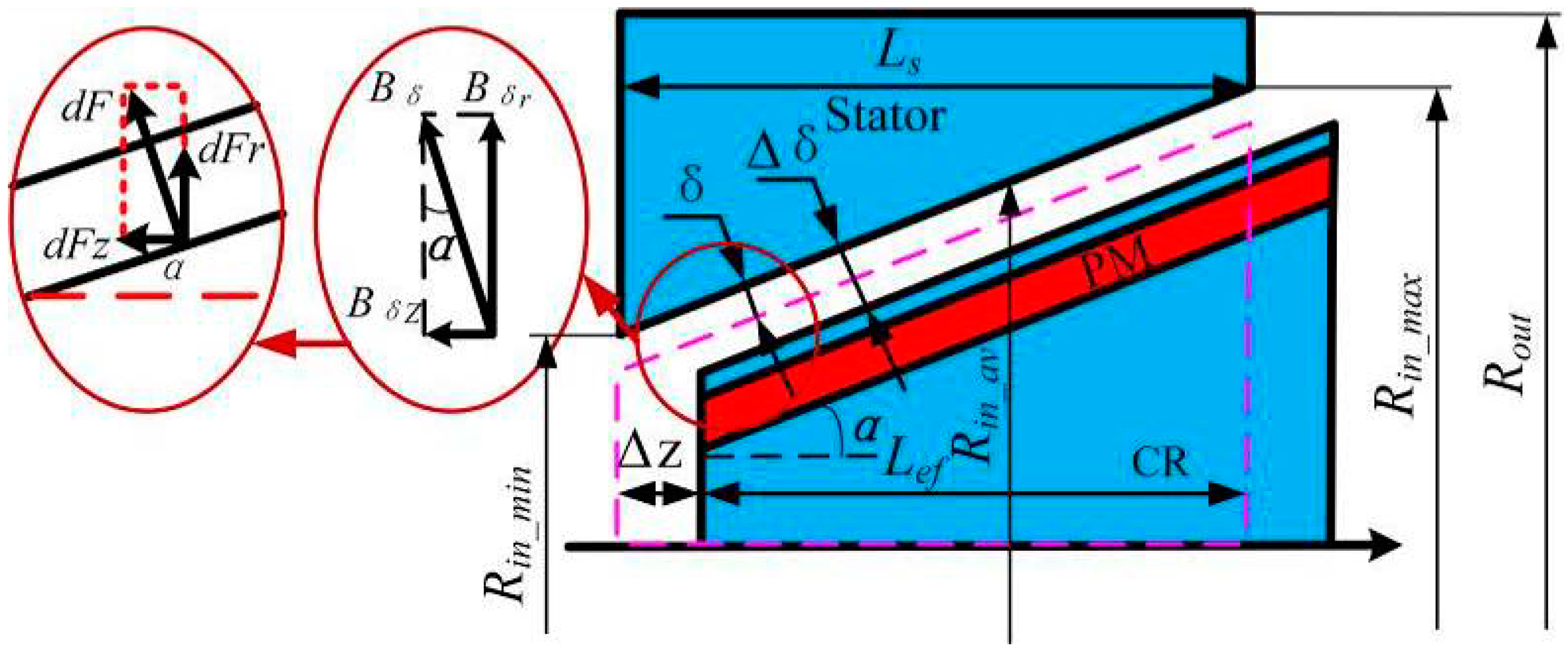
2.1. Theoretical Calculation for Magnetic Circuit

In order to obtain simple design principles, the following assumptions are proposed: Equation (1) the relative permeability of the iron cores is infinite and Equation (2) the leakage flux and the cogging effect are ignored. The air gap magnetic field is synthesized by PM magnetic field and armature reaction magnetic field if the saturation is not considered. According to the double reaction theory of synchronous motor, armature reaction can be equivalent to the superposition of the effect of the d-axis and the q-axis component [16].
According to the magnetic circuit method, the flux density Bδ under OCC can be expressed as:
B δ ( θ , Z ) = B δ 0 ( θ , Z ) + B 1 d ( θ , Z ) + B 1 q ( θ , Z )
where, Bδ0, B1d; B1q, θ and Z are the no-load air-gap flux density, the d-axis armature reaction flux density, the q-axis armature reaction flux density, the circumferential angle and the axial position of the rotor, respectively.
At a fixed axial position, the specific expressions of the flux densities are as follows:
{ B δ 0 ( θ ) = B r h m h m b δ b m + μ 0 ( δ + Δ z sin α ) sin ( p θ ) B 1 d ( θ ) = 3 μ 0 N s π ( δ + Δ z sin α ) I d K dp F 1 d sin ( p θ ) B 1 q ( θ ) = 3 μ 0 N s π ( δ + Δ z sin α ) I q K dp F 1 q sin ( p θ + π 2 )
where, μ0 is the permeability of vacuum (μ0 = 4π × 10−7 H/m); Br, hm, bδ and bm are the PM remanence, the PM thickness (length of the magnetization direction), the PM width and the width of air-gap per pole, respectively; Kdp, Ns, Id, Iq, F1d, F1q and p are the winding coefficient, turn numbers per phase, d-axis current, q-axis current, d-axis magnetic potential, q-axis magnetic potential and pole pairs, respectively.
When the motor carries load, B1d is of the same phase as Bδ0, enhancing or weakening the magnetic field. While, B1q is in the orthogonal phase of Bδ0, enhancing the magnetic field and causing waveform change, and no-load of CR-PMSM, Equation (3) could be approximately simplified to be:
B δ 0 = Φ δ 0 b δ L ef = B r h m h m b δ b m + μ 0 ( δ + Δ z sin α )
where, Φ δ 0 = F m R m + R δ , Fm is the magneto-motive force (MMF) in a closed magnetic circuit, Rm and Rδ are the reluctance in the PM and air gap, respectively.
Among various types of the rotor topologies, surface-type and interior-type CR-PMSM, as shown in Figure 2, are studied and compared in this paper.
For the surface-type CR-PMSM as shown in Figure 2a, the width of PM is equal to the width of air-gap per pole (bδ/bm = 1), and the flux passes through the PM twice in a closed magnetic circuit. For the interior-type CR-PMSM as shown in Figure 2b, the width of PM can be selected without regard of the air-gap width, and the flux passes through the PM once. If the width of the PM is bigger than that of air gap (bδ/bm < 1), the same rotor displacement will have a greater influence on the air-gap flux density, as shown in Figure 3.
In order to keep the stator slot width bslot and height hslot dimension the same in the axial direction (z axis), and a constant the radius of stator Rout. So, through the magnetic circuit method, the maximum and minimum radius of the stator Rin_m can be calculated by:
R in _ m = R in _ av ± L s 2 tan α
where, Rin_min take the value of “−” and Rin_max take the value of “+”.
Then, the stator slot width bslot, tooth width btooth_m and yoke height hyoke_m can be expressed as:
{ b slot = ( 1 k s ) π 2 R in _ av Q s b tooth _ m = 2 π R in _ m Q s b slot = 2 π ( R in _ av ± L s 2 tan α ) Q s h yoke _ m = R out R in _ m h slot = R out ( R in _ av ± L s 2 tan α ) h slot
where, ks and Qs are the ratio of tooth width to pitch and the stator slot number, respectively.
So, the flux density of stator tooth Btooth_m and yoke Byoke_m can be expressed as:
{ B tooth _ m = B δ 2 π R in _ av Q s b tooth _ m = B δ R in _ av ± L s 2 tan α k s R in _ av ± L s 2 tan α B yoke _ m = Φ δ 0 2 L s h yoke _ m = B δ b δ R out ( R in _ av ± L s 2 tan α ) h slot
As shown in Equation (7), the flux density of the stator tooth Btooth_m and yoke Byoke_m varies with the axial position and the cone angle of the rotor. Inevitably, the torque density of CR-PMSM will be reduced slightly indicated by the parameter (Lstan α). The flux density of yoke Byoke_m can be adjusted by the outer radius Rout independently. The relationship between the flux density of tooth Btooth_m and the length-to-diameter is:
L s 2 R in _ av = ± B r k s B tooth _ m B δ B δ B tooth _ m
In order to maintain a rational magnetic loading (such as Bδ = 0.7 T, Btooth_max = 1.54 T, and ks = 0.4), the ratio of length to diameter should meet the condition that Lstanα/Rin_av < 0.15.

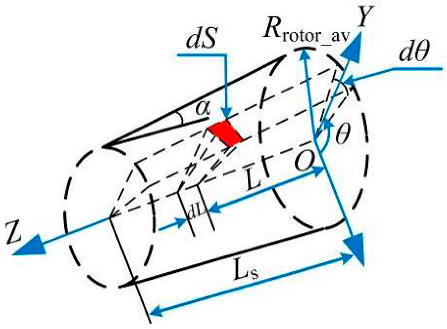
2.2. Modeling of Axial Magnetic Force Produced for CR-PMSM

In general, the flux lines in the air gap length δ of a low saturated PMSM are nearly perpendicular to the surface of the stator [17]. Unlike general cylindrical motors, the flux density Bδ in the conical air gap can be decomposed into a radial and an axial component. If no rotor eccentricity occurs, the sum of the radial forces acting between the stator and the rotor is zero. Only the axial force is acting on the stator and the rotor, respectively [18]. The axial magnetic force can be calculated by the virtual displacement method [19] or the Maxwell stress tensor method [20]. The latter is employed in this paper for investigating the magnetic force, and the force components per air gap area element can be determined by:
f = [ f r f t f z ] = 1 2 μ 0 [ ( B δ n 2 B δ t 2 ) cos α 2 B δ n B δ t ( B δ n 2 B δ t 2 ) sin α ]
where fr, ft and fz are respectively the radial, tangential and axial component of the force, of which fr and fz compose to the normal component; Bδn and Bδt are the normal and tangential component of the air gap flux density.
As can be seen from Figure 4, the unit area dS on the rotor surface can be modeled and analyzed by:
d S = 0 2 π L s 2 L s 2 ( R rotor _ av δ L tan α ) sin α tan α d θ
In a low saturated PM machine, the flux lines in the air gap are nearly perpendicular to the outer surface of the rotor, which implies that Bδt << Bδn, so the force densities could be further simplified to:
f = [ f r f t f z ] 1 2 μ 0 [ B δ n 2 cos α 2 B δ n B δ t B δ n 2 sin α ]
Substituting Equations (2), (3) and (10) into (11), yields:
F z = 1 2 μ 0 [ B ˙ δ 0 + B ˙ 1 d + B ˙ 1 q ] 2 sin α d S
Terms with ‘·’ on head in Equation (12) mean that they are vector quantities. Since the q-axis flux is in theory perpendicular to the d-axis flux, Equation (12) could be approximately simplified to be
F z 1 2 μ 0 [ B ˙ δ 0 + B ˙ 1 d ] 2 sin α d S
According to Equations (12) and (13), once the CR-PMSM rotates, an axial magnetic force will be produced, and it will change with the stator current.
When the CR-PMSM under no-load, Equation (13) could be approximately simplified to be:
F z 1 2 μ 0 B δ 0 2 S sin α
In conclusion, the axial magnetic force, no-load back EMF and electromagnetic torque are mainly relevant to the air gap magnetic field, air gap length, outer diameter of the CR, core length and cone angle, etc. [21] From Equations (2) and (13), once the geometry of the CR-PMSM is fixed, the axial force Fz can be magnetically enhanced or weakened by changing the amplitudes of the dq-axis currents [22,23]. Thus, the analysis of Bδ will be necessary for the calculation of Fz.
In order to determine the axial magnetic force performance of CR-PMSM, when the CR moved outside in axial direction Δz and enhanced (or weakened) by changing the amplitudes of the d-axis current, a parameter of axial magnetic force ratio FΔz should be expressed as:
{ F Δ z ( α , Δ z ) = F Δ z = 0 F Δ z _ max F Δ z = 0 × 100 % F i d ( α , i d ) = F i d = 0 F i d _ max F i d = 0 × 100 %
where, FΔz = 0 and FΔz_max are the no-load axial magnetic force at the rated speed when Δz = 0 and Δz = max, Fid = 0 and Fid_max are the load axial magnetic force at the rated speed when id = 0 and id = max.
As can be seen from Equation (15), when the cone angle of CR-PMSM is set, the axial magnetic force is only related to the axial displacement Δz of the CR and the id current of the stator, so Equation (15) could be approximately simplified to be:
F Δ z , i d ( Δ z , i d ) = 1 ( 1 C B ) ( 1 C s )
The axial magnetic force changing ratio FΔz,id can be decomposed to the air gap flux density changing ratio CB and the effective air gap space decrease ratio CS:
{ C B ( Δ z , i d ) = ( 1 B δ 0 B δ ) × 100 % C S ( Δ z ) = Δ z L s × 100 %
Equation (17) shows the relationship between the axial magnetic force changing ratio FΔz,id and the CR axial displacement Δz under the id current of the stator. Meanwhile, 6° is an appropriate cone angle, which not only keeps FΔz,id an approximately linear relation with wide range of Δz, but also results in the balance point of good f axial magnetic force changing ratio and not quite a large displacement.

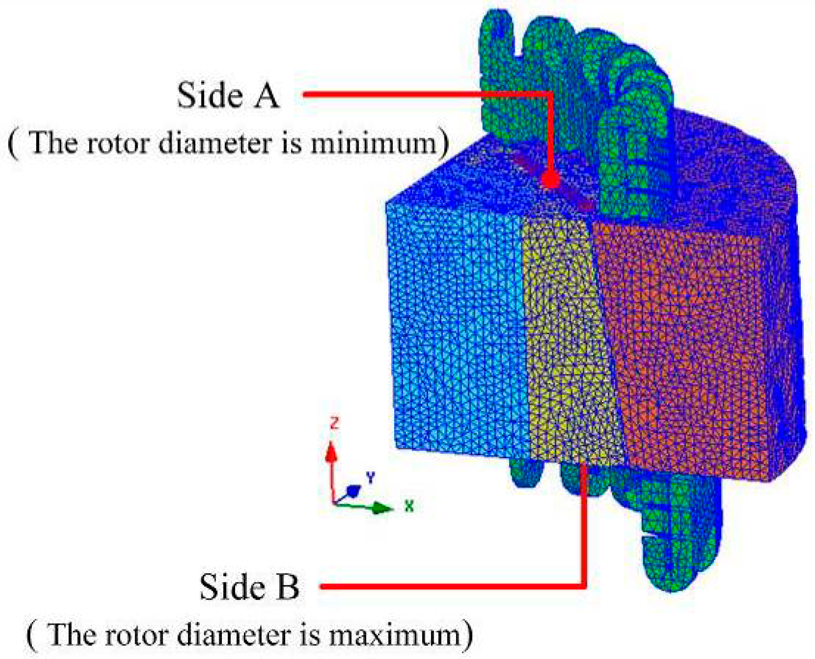
3. 3-D FE Analysis of CR-PMSM

The axial magnetic force can be obtained by 3-D FEM when the armature winding is with different d, q-axis currents [18]. The main geometry and electrical parameters of the prototype machine are provided in Table 1.
In order to save calculation time, according to the structural symmetry of the motor, a quarter of 3-D model is established by manual modeling using ANSYS software (ANSYS 16.0, Ansys Inc., Canonsburg, PA, USA), as shown in Figure 5. For distinction, the end surface with the minimum rotor diameter of the machine is defined as side A, and the other end surface of the machine (with the maximum rotor diameter) is defined as side B.

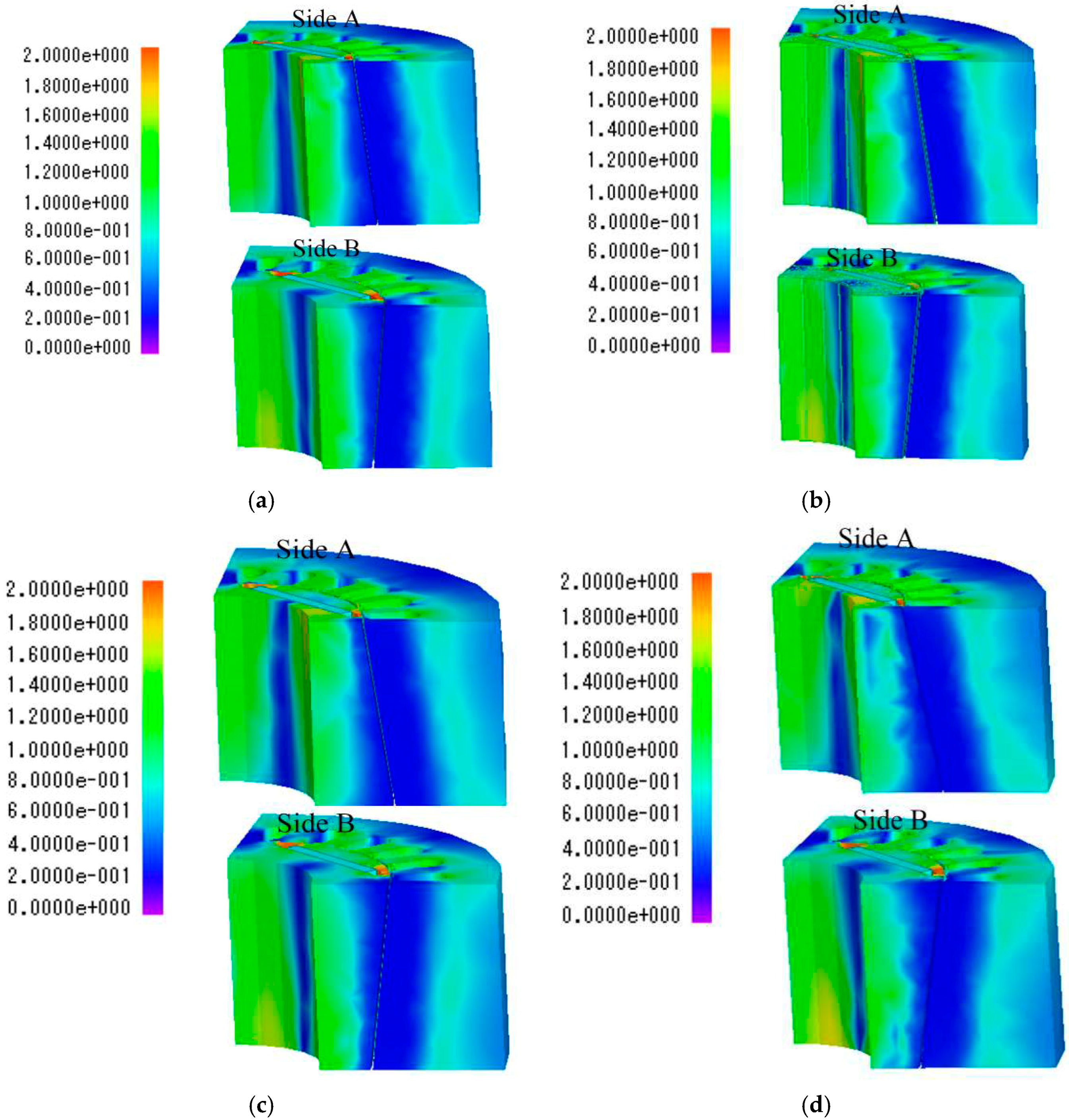
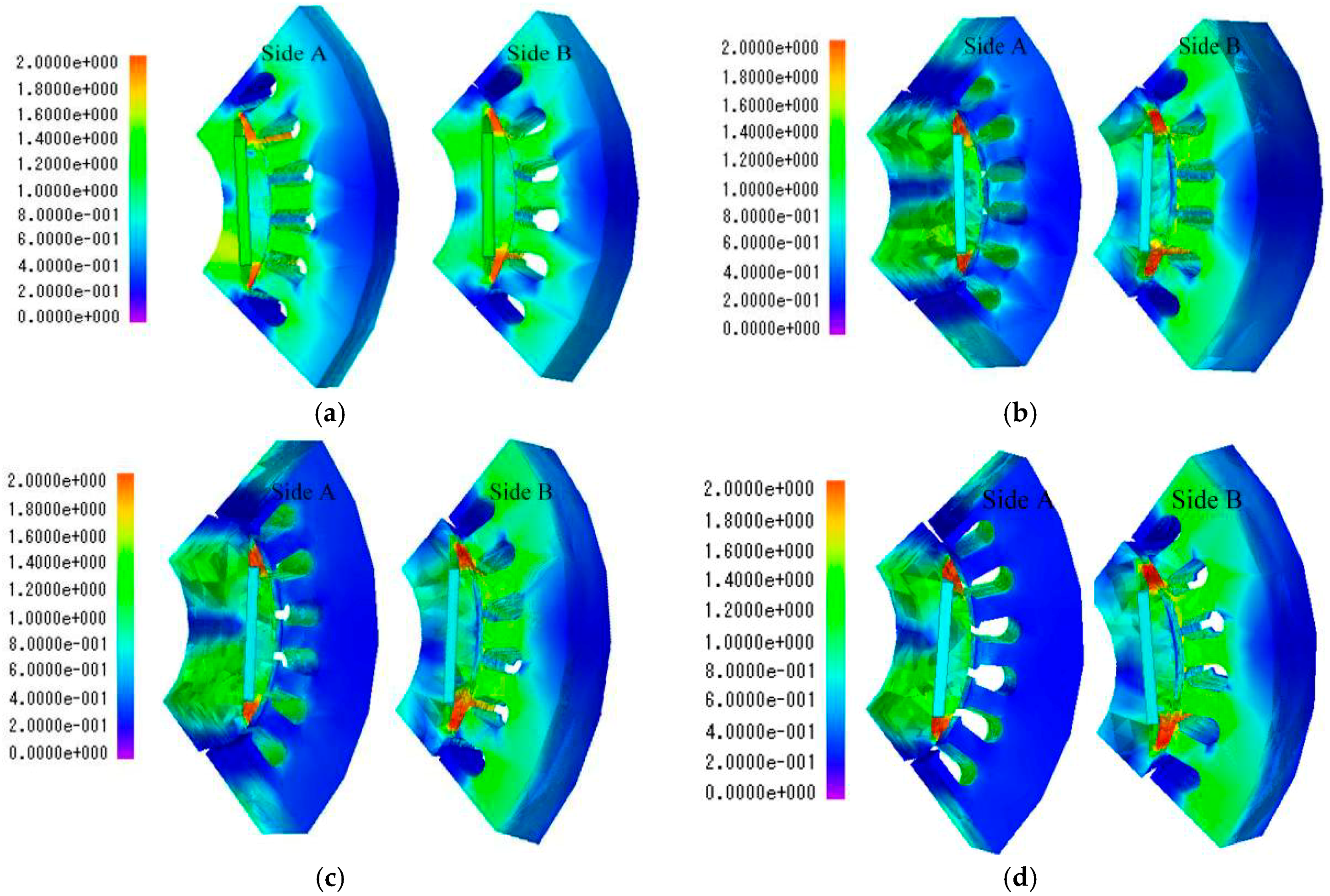
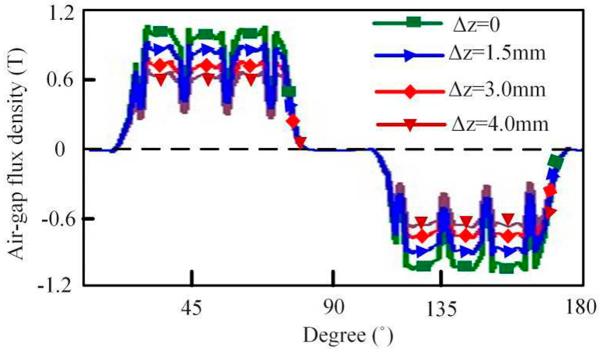
3.1. Magnetic Field Distribution

By using 3-D FE simulation, the magnetic field of the motor with cone angle from 4°–8° is analyzed, as shown in Figure 6a–d.
It can be seen from Figure 6 that the presence of the cone angle will make the end CR magnetically dense. When the cone angle is 8°, the degree of stator saturation is obvious, so it is necessary to properly design the cone angle to prevent the CR-PMSM from operating in an over-saturated state. When the cone angle is fixed, the longer the axial length of the core, the larger the diameter of the stator and rotor changes, and the more prone to saturation. Therefore, the core should not be designed too long.
Figure 7 shows the 3-D magnetic-field distribution of the air-gap magnetic density Bδ, which is decomposed into the radial component Bδr and the axial component Bδz. As the cone angle increases, the radial magnetic density amplitude decreases slightly, and the axial magnetic density rises slightly. This tendency can be clearly seen when the cone angle is 6° and the cone angle is 8°.
The flux density distribution with different axial displacement of CR is shown in Figure 8. At the larger end of the stator bore, the magnetic density on the top of the stator tooth appears to be partially saturated, and the magnetic density on the top of the stator tooth is obviously reduced at the smaller end of the stator core.
Figure 9 shows the magnetic-field distribution of the air-gap flux density under OCC with different CR axial displacement, including the radial component Bδr and the axial component Bδz.
The amplitudes of air-gap flux density Bδ along the axial direction are shown in Figure 10. It can be seen that the amplitude of Bδ will be decreased accordingly as the CR axial displacement, but the change gradient is smaller and smaller. Although the amplitude of the axial component Bδz is small. Thus, the calculation of Bδ will be necessary for the calculation of the magnetic axial force.

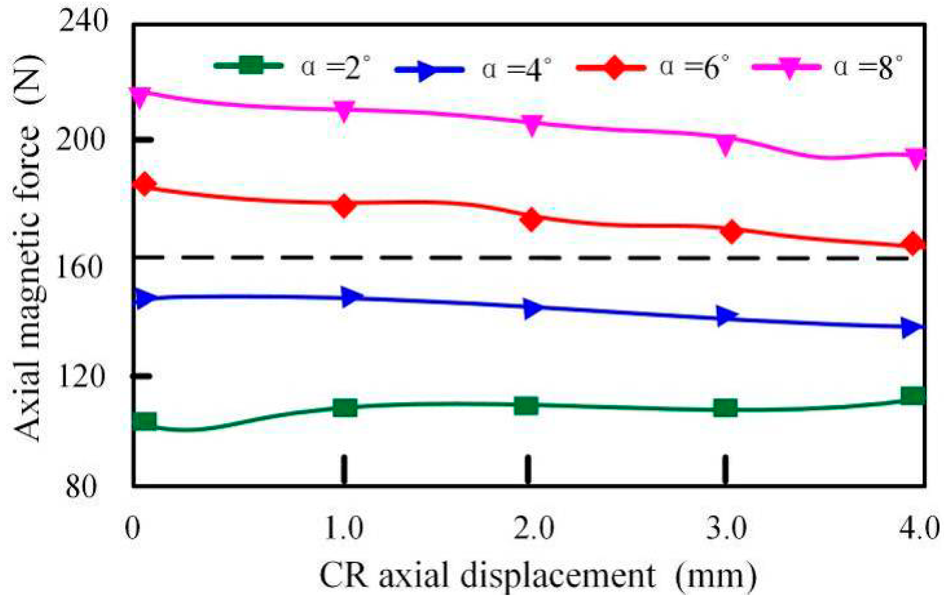
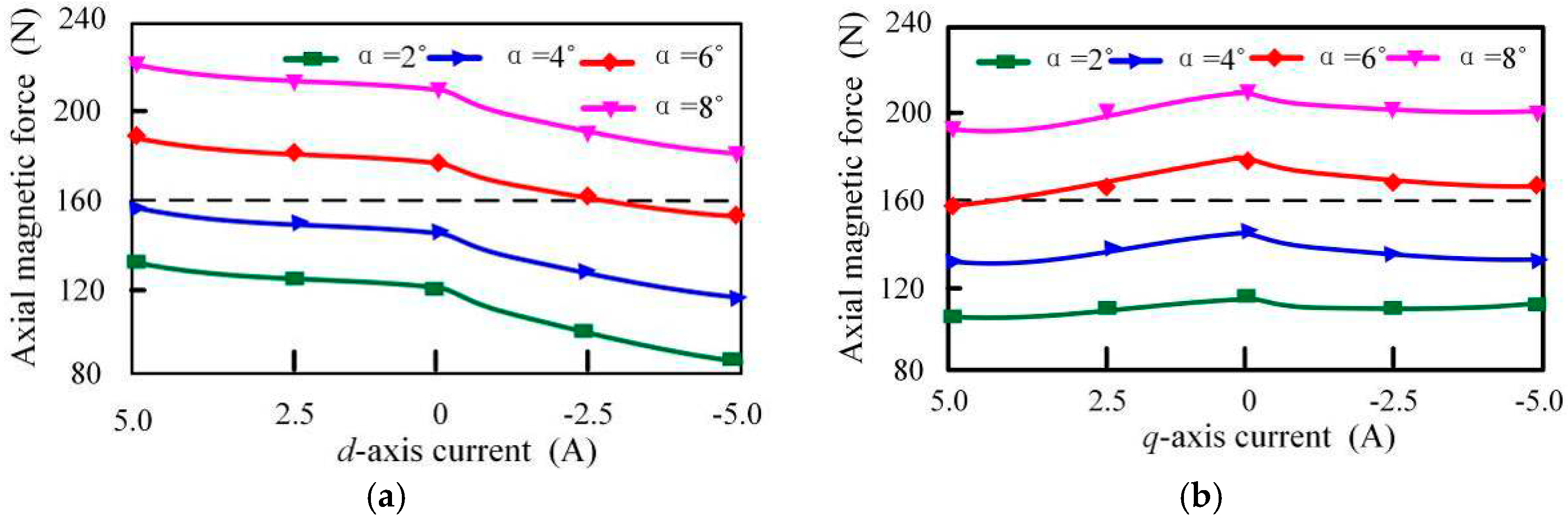
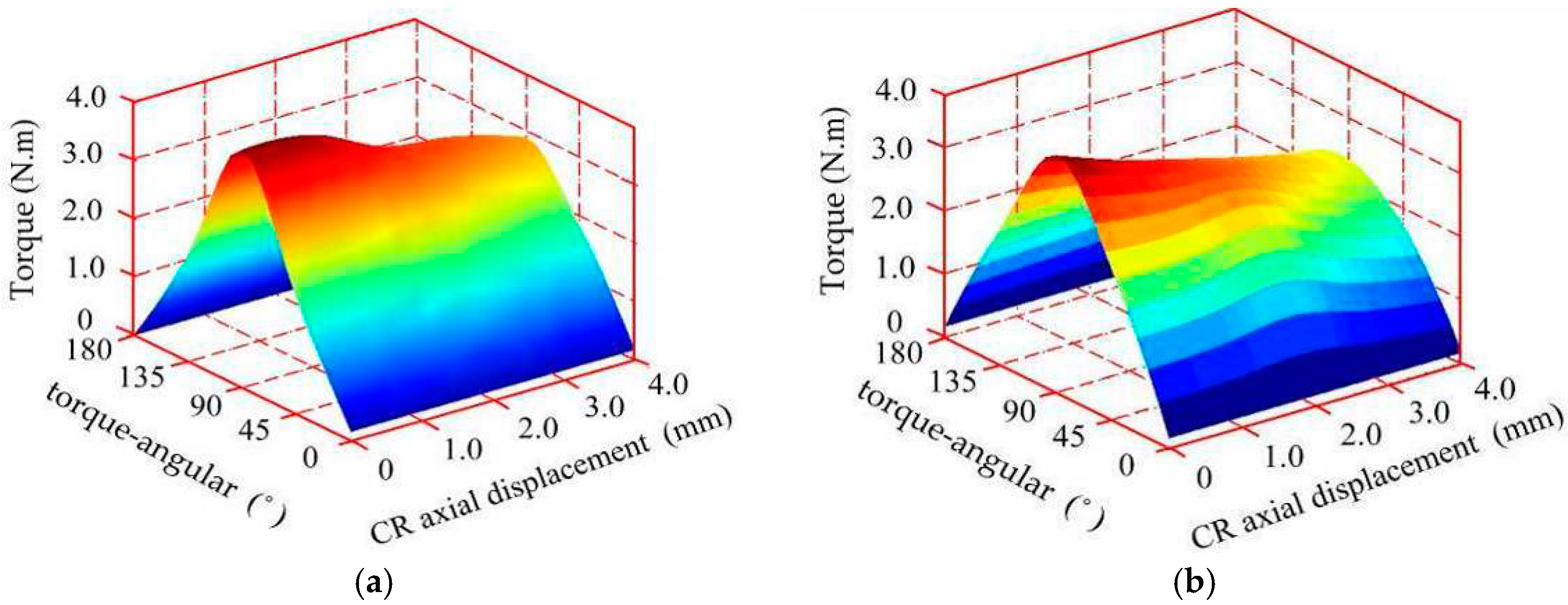
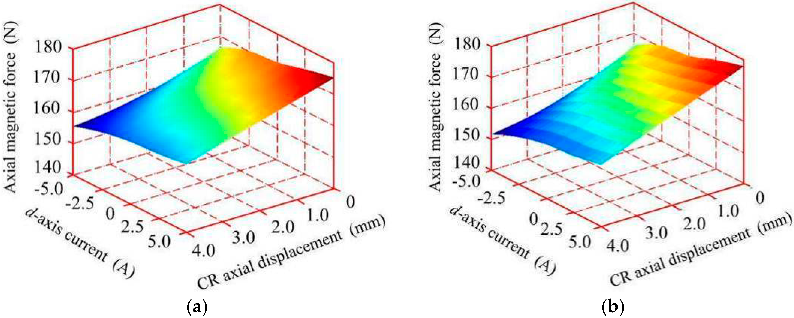
3.2. Analysis of the Axial Magnetic Force

It can be seen from Figure 11 that when α is small, FZ increases slowly with a small axial displacement, and when α is larger, FZ decreases linearly with the axial displacement.
As can be seen from Figure 12, the axial magnetic force has only a quite slight increase with the increase of q-axis current, which confirms the previous analysis and conclusion in Equations (12) and (13). In addition, the magnetic axial force will increase with id.
Based on the simulation model, the operating performance curves of the CR-PMSM can be obtained, as shown in Figure 13. The x-coordinate is the ratio of output power (Pout) to rated power (PN), and the y-coordinate is normalized, including the power factor (cosφ), efficiency (η), the ratio of current (I) and the ratio of torque (Te).
More simulation results are presented in Section 4, comparing with the experimental results, to verify the design rationality.

4. Experimental Validation and Analysis

The technique flowchart for design, analysis and validation of the proposed CR-PMSM is described in Figure 14, which contains four steps. Steps 1 to 3 mainly focus on the design and simulation of the motor, which all belong to theoretical research and have been discussed in detail in the sections above. In this section, the operation of the prototype experiment and the related analysis results in detail will be introduced.

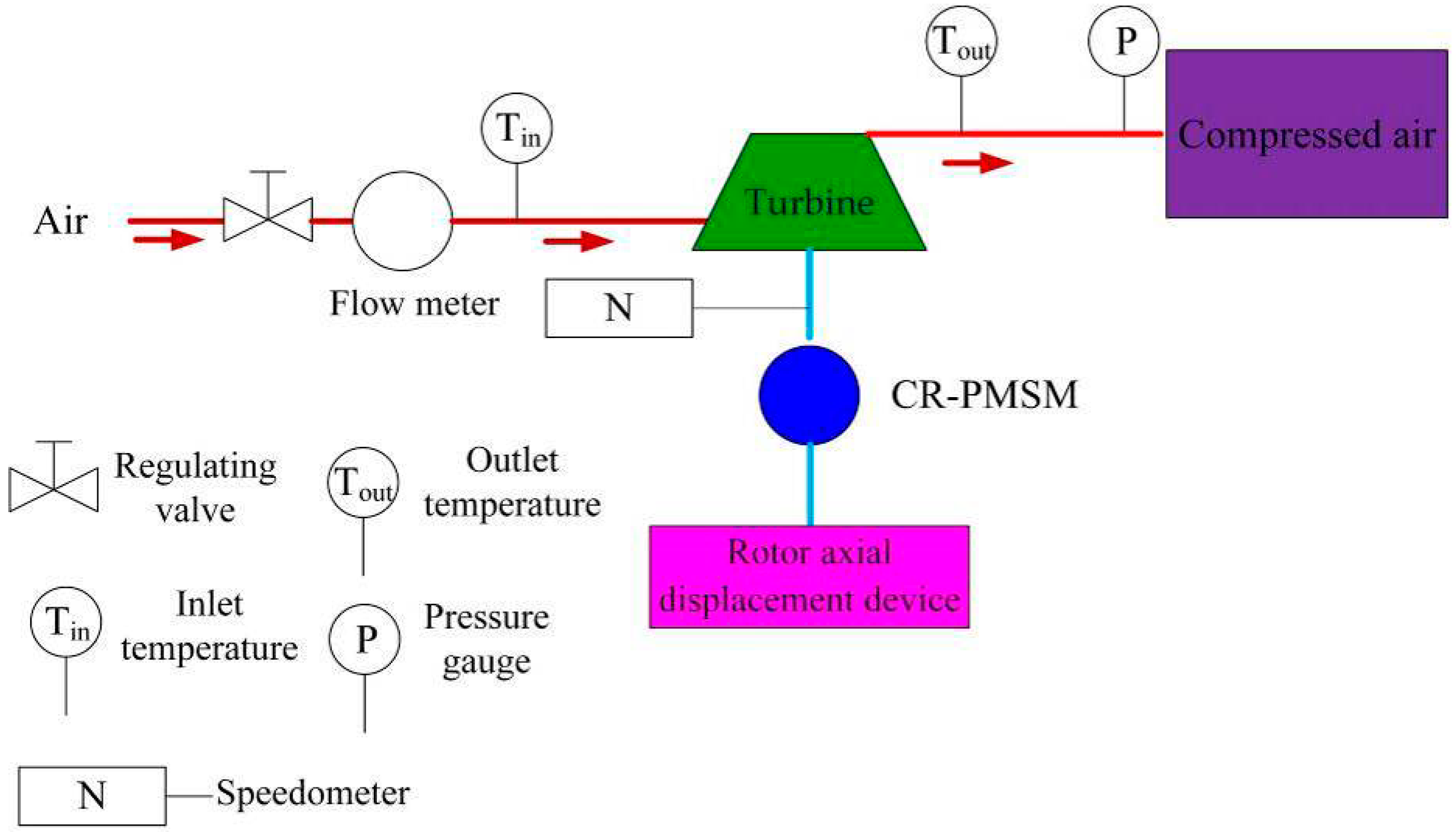
4.1. Test Rig of Prototype Machine

In order to evaluate the performance of developed CR-PMSM, experimental system is designed and built. As shown in Figure 15, the parameters that can be adjusted on experimental platform are the flow and the pressure of compressed air. The inlet of the turbocompressor is connected to the air source, and the flow rate of normal air into the turbine-compressor can be controlled by adjusting the valve. The inlet pipeline is equipped with a thermal resistance and mass flowmeter to measure the temperature and flow parameters of the air at the inlet. While, the outlet pipeline is equipped with a thermal resistance and a high-precision pressure gauge to measure the temperature and pressure of the compressed air. The compressed air is injected into the pressure tank, and under rated condition the output flow rate is 250 kg/h and the pressure is 0.15 MPa. The turbocompressor is directly connected to the shaft of the conical motor, driven by a special frequency converter, and the other end of the motor shaft is equipped with a rotor axial displacement device.
A 2.0 kW, 6000 r/min prototype machine with a cone angle of 6° was fabricated. The whole prototype test rig, which is composed of a CR-PMSM prototype, an oscilloscope, a turbo-compressor, a volute and a controller is shown in Figure 16. Firstly, the rotor of the CR-PMSM will rotate, and due to the connection of the shaft and the turbine, the turbo-compressor starts to rotate, converting the electricity power into mechanical energy. According to the flowchart shown in Figure 14, when the motor-turbine system runs at a steady speed, the valve size is adjusted to change the load, which will cause the changes of the axial force of the turbine; at this time, the axial position of the rotor and the stator current should be controlled to change the axial electromagnetic force of the CR-PMSM, thereby suppressing the axial force of the turbine as the pressure changes.
It should be noted that the thimble of the axial displacement device is closely attached to the shaft end of the motor. Restricted by the experimental conditions, the axial length of the thimble can only be adjusted by manual manipulation of the rotary handle, to drive the motor to move axially and obtain the required axial position of the rotor. Meanwhile, the maximum axial displacement is 4.5 mm, which is measured by the displacement sensor.

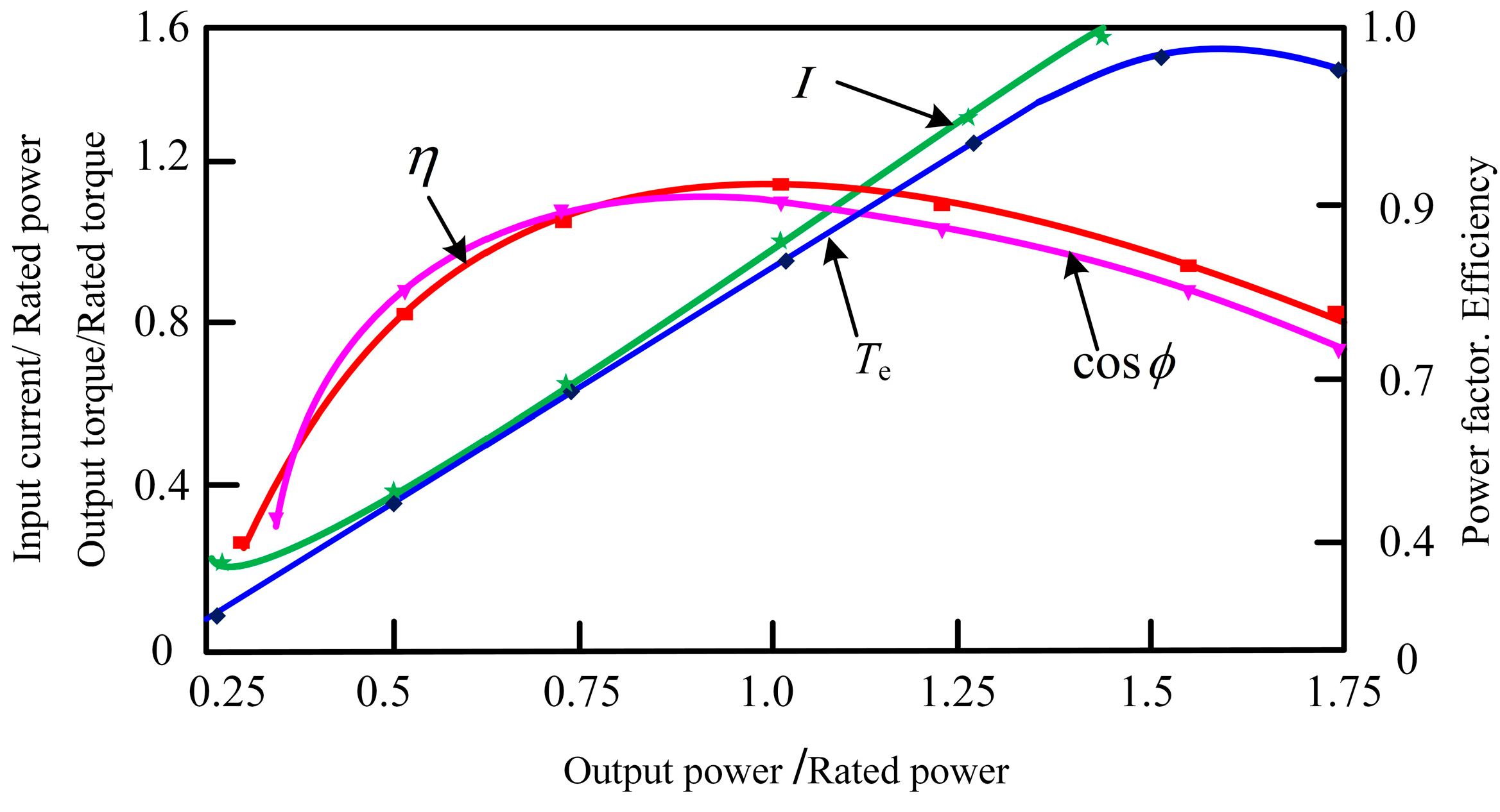
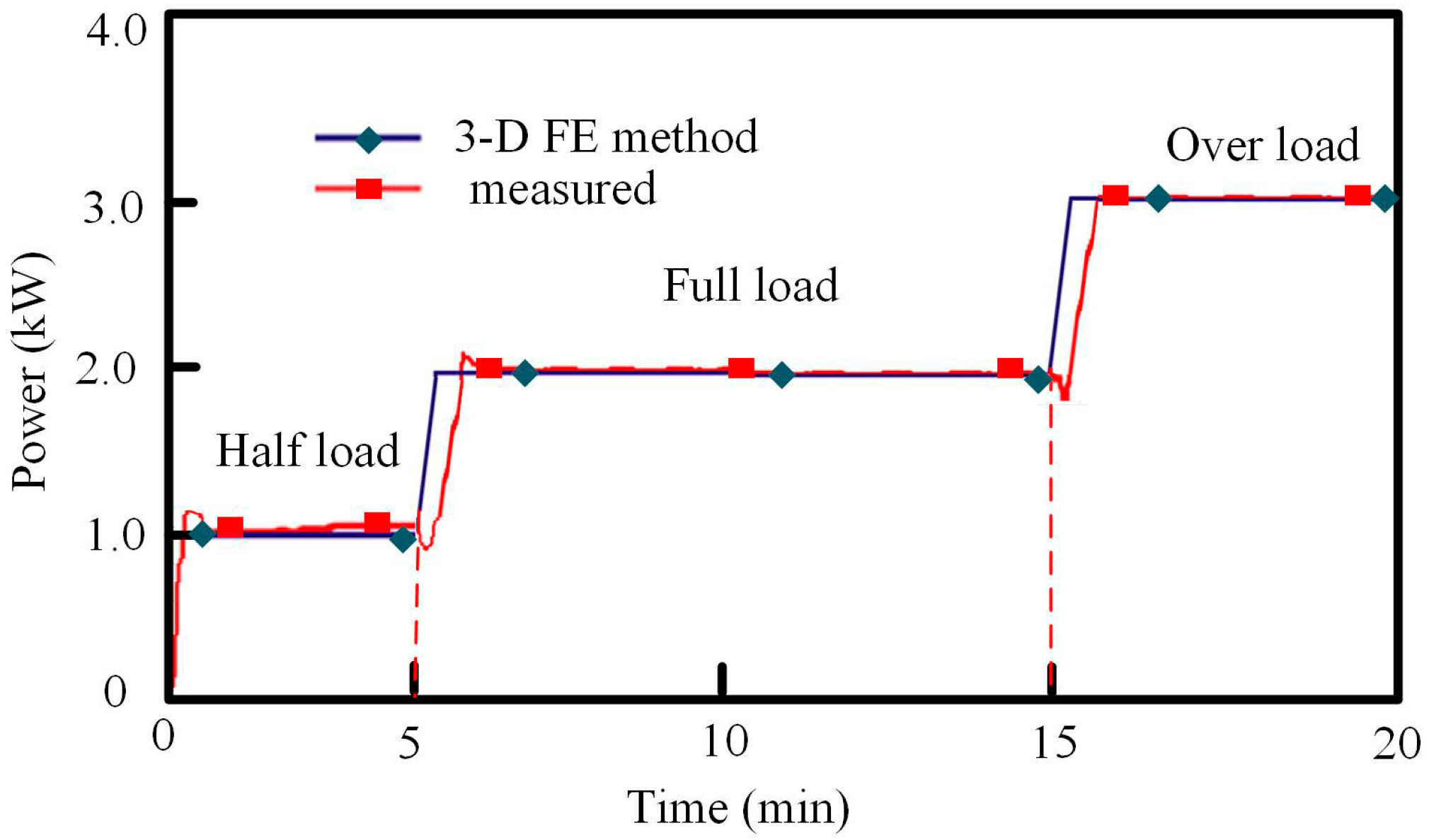
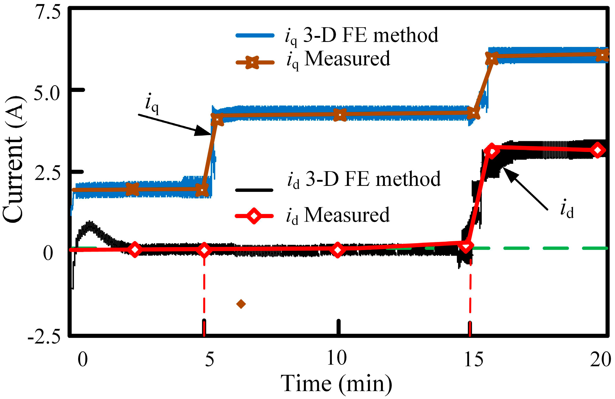
4.2. Analysis of Results

The no-load back EMF is measured and depicted in Figure 17a, of which the RMS value is about 238.2 V. Compared with the 3-D FEM result, it has a quite slight difference (3%). As shown in Figure 17b, with the increase of CR axial displacement, the no-load back EMF of the motor basically decreases linearly.
The back EMF by theoretical analysis with 3-D FEM is also given in Figure 16. Because of the material parameter differences between the actual prototype and the simulation, and the influence of the manufacturing process, the calculated back EMF is larger, especially at the initial stage of the CR axial displacement. The match among the three methods is nevertheless quite good. Note that the decreasing slopes of the back EMF for all three methods are the same, this proving the exactness and validity of the analytic calculation.
During the test process, the outlet pressure should be set to adapt to 50% (half load), 100% (full load) and 150% (over load) of rated load, respectively, so the output power curve should be set and adjusted according to the 3-D FE simulation curve shown in Figure 18 to carry out the corresponding load test verification, but of course, the actual tested output power curve deviates slightly from the simulation curve, because the response to load changes is somewhat delayed, and the curve shows transient fluctuations due to disturbances caused by the load change.
According to Figure 12, the d-axis current has a greater influence on the axial magnetic force, while the q-axis current mainly affects the output power. In order to verify the influence of current on axial force, adjust the input current of the motor while keeping the rotor axial displacement unchanged (Δz = 0), and the d, q-axis currents and the axial magnetic force can be measured. On this basis, the current curves and axial force curve can be obtained, as shown in Figure 19 and Figure 20, which are basically consistent with the simulation results.
Tests of the axial magnetic force are also carried out when both the rotor axial displacement and the input current are changed. The test results are organized into a 3-D curved surface, as shown in Figure 21b, which is similar to the simulated results shown in Figure 21a. It can be seen that when the d-axis current is enhancing the flux (id > 0), the greater the axial magnetic force, when the straight axis current is demagnetization (id < 0), the reverse is the case.
The overall change trend of the torque-angular (β) characteristics of the prototype is shown in Figure 22. It can be seen that the torque decreases monotonically with the increase of the axial position of the rotor under the condition of a certain rotor angle. Compared with the 3-D FE method result, it has a quite slight difference (2%), which confirms the accuracy of developed 3-D model.
It should be noted that since the rotor axial displacement is manually adjusted, the continuity of the test data is not good, thus the graphics shown in Figure 21b and Figure 22b are not smooth. The axial force of the rotor shaft with a turbine (axial force resultant) is tested, and the result curve is shown in Figure 23, where it can be seen that the axial force of the turbine is well counteracted by the axial magnetic force generated by the CR-PMSM, and the average value of total axial force is strictly constrained around zero, but unlike the ideal curve obtained by simulation, which is always zero, there are small disturbances in the test curve, which occur at those load change moments.
The efficiency of the CR-PMSM direct-drive turbine system is calculated by using the measured data including the input power, outlet pressure and flow rate of the turbine. Based on the turbine load characteristic, the efficiency curve varying with different load conditions can be obtained, as shown in Figure 24. A conventional PMSM direct-drive turbine system with the same power is also tested for comparison. It can be seen that the efficiency of the CR-PMSM direct-drive turbine system is about 1.5 percentage points higher at different load conditions.
The main comparison parameters of the two motors are listed in Table 2. The motor constant (CA) of the CR-PMSM is basically close to but slightly lower than that of the conventional PMSM. Meanwhile, because the inner diameter of each stamping sheet of the stator core is different and the outer diameter of each stamping sheet of the rotor core is also different, the stamping dies and the laminating dies are more complicated than that of conventional machines. So, the manufacturing cost of the CR-PMSM is higher than that of conventional PMSM.
For this prototype, the manufacturing cost of the main components is listed also in Table 2, which indicates that manufacturing cost of this prototype CR-PMSM is about 16.7% higher than that of a conventional PMSM with the same power level and almost the same volume. Of course, if large-scale production is carried out, the cost of each motor will be reduced. How much reduction is related to the scale of production and the power of the motor, cannot be generalized.
Figure 25 shows the measured line voltage (Ua) and current (Ia and Ib) at half load, full load and over load conditions, and the waveform presents a quite good sinusoidal.
The output performances at different load conditions is listed in Table 3, which shows there is a quite small difference (≤5%) between the simulated and measured results.
Based on the above analysis, the axial magnetic force only has a greater increase with the increase of d-axis current, which confirms the previous analysis and conclusions in Equations (12) and (13). As shown in Figure 17 and Table 3, the air gap flux density changing ratio CB and the effective air-gap space decrease ratio CS is listed in Table 4.

5. Conclusions

In this paper, the CR-PMSM is proposed to realize the axial force suppression of the motor-turbine system, without balance devices. The magnetic field characteristics, no-load back EMF and axial magnetic force of the motor were analyzed. The change regulations were obtained, which indicates that the air gap magnetic field weakens with the increase of the CR axial displacement and the d-axis current demagnetization current has a greater influence on the axial magnetic force. The parameter of the axial magnetic force changing ratio FΔz,id was defined to calculate the axial magnetic force performance. The results of theoretical calculation and experiment research show that the maximum axial displacement of the CR Δz_max and d-axis current are the key parameters which influence the flux weakening ratio FΔz,id. The above conclusions can be applied to both surface-type and interior-type PMSMs. In the motor design process, an interior-type rotor and a small length to diameter ratio are appropriate properties for CR-PMSM. However, there are still some additional research work to be done and perfected in the future. It is quite challenging to derive the expression of axial force with respect to d-axis current and cone angle, as well as to analyze the efficiency in a wide speed range, which will be the priority of future work.

Author Contributions

Conceived the theory and built the model, J.W., S.H.; Performed the experiments and analyzed the data, J.W., C.G., Y.F.; Wrote the paper, C.G., Y.F.; Funding acquisition, S.H., Y.F.

Funding

This work was supported in part by the National Natural Science Foundation of China under Grant 51737004, 51407064 and in part by the Natural Science Foundation of Hunan Province, China under Grant 2018JJ2044.

Conflicts of Interest

The authors declare no conflict of interest.

References

  1. Lopez-Torres, C.; Riba, J.R.; Garcia, A.; Romeral, L. Detection of Eccentricity Faults in Five-Phase Ferrite-PM Assisted Synchronous Reluctance Machines. Appl. Sci. 2017, 7, 565. [Google Scholar] [CrossRef]
  2. Oumaamar, M.E.; Maouche, Y.; Boucherma, M.; Khezzar, A. Static air-gap eccentricity fault diagnosis using rotor slot harmonics in line neutral voltage of three-phase squirrel cage induction motor. Mech. Syst. Signal Process. 2017, 84, 584–597. [Google Scholar] [CrossRef]
  3. Glowacz, A. Fault diagnostics of acoustic signals of loaded synchronous motor using smofs-25-expanded and selected classifiers. Tehnicki Vjesnik-Technical Gazette 2016, 23, 1365–1372. [Google Scholar]
  4. Kurokawa, J.; Toykokura, T. Study on the axial thrust of the radial flow turbomachinery. In Proceedings of the 2nd International JSME Symposium Fluid Machinery and Fluidics, Tokyo, Japan, 4–9 September 1972; pp. 31–40. [Google Scholar]
  5. An, Y.; Liu, G.; Meng, Z.; Wang, P.; Wen, H. Analysis and experiment of magnetic force in permanent magnet axial thrust balance structure for canned motor pump. In Proceedings of the International Conference on Intelligent Control and Information Processing, Dalian, China, 12 August–15 August 2010; pp. 732–734. [Google Scholar]
  6. Wang, K.; Sun, J.; He, Z.; Song, P. Prediction of axial thrust load acting on a cryogenic liquid turbine impeller. In Proceedings of the ASME Turbo Expo, Vancouver, BC, Canada, 6–11 June 2011; pp. 487–498. [Google Scholar]
  7. He, Y.L.; Deng, W.Q.; Peng, B.; Ke, M.Q.; Tang, G.J.; Wan, S.T.; Liu, X.Y. Stator Vibration Characteristic Identification of Turbogenerator among Single and Composite Faults Composed of Static Air-Gap Eccentricity and Rotor Interturn. Shock Vib. 2016, 2016, 5971081. [Google Scholar] [CrossRef]
  8. Chai, F.; Zhao, K.; Li, Z.; Gan, L. Flux weakening performance of permanent magnet synchronous motor with a conical rotor. IEEE Trans. Magn. 2017, 53, 536–545. [Google Scholar] [CrossRef]
  9. Munteanu, G.; Binder, A.; Dewenter, S. Five-axis magnetic suspension with two conical air gap bearingless PM synchronous half-motors. In Proceedings of the International Symposium Power Electronics, Electrical Drives, Automation and Motion, Sorrento, Italy, 20–22 June 2012; pp. 1246–1251. [Google Scholar]
  10. Chen, Q.; Liu, G.; Zhao, W.; Shao, M. Nonlinear adaptive lumped parameter magnetic circuit analysis for spoke-type fault tolerant permanent-magnet motors. IEEE Trans. Magn. 2013, 49, 5150–5157. [Google Scholar] [CrossRef]
  11. Raminosoa, T.; Rasoanarivo, I.; Meibody-Tabar, F.; Sargos, F.M. Time-stepping simulation of synchronous reluctance motors using a nonlinear reluctance network method. IEEE Trans. Magn. 2008, 44, 4618–4625. [Google Scholar] [CrossRef]
  12. Immonen, P.; Ruuskanen, V.; Pyrhonen, J. Moving magnet linear actuator with self-holding functionality. IET Electr. Syst. Transp. 2018, 8, 182–187. [Google Scholar] [CrossRef]
  13. Kano, Y.; Kosaka, T.; Matsui, N. Simple nonlinear magnetic analysis for permanent-magnet motors. IEEE Trans. Ind. Appl. 2005, 41, 1205–1214. [Google Scholar] [CrossRef]
  14. Tangudu, J.K.; Jahns, T.M.; El-Refaie, A.; Zhu, Z.Q. Lumped parameter magnetic circuit model for fractional-slot concentrated-winding interior permanent magnet machines. In Proceedings of the IEEE Energy Conversion Congress and Exposition, San Jose, CA, USA, 20–24 September 2009; pp. 2423–2430. [Google Scholar]
  15. Feng, X.H. Taper Asynchronous Motor, 1st ed.; Huazhong University of Science & Technology Press: Wuhan, China, 1996; pp. 15–21. (In Chinese) [Google Scholar]
  16. Ruuskanen, V. Effect of armature reaction on the core losses of the permanent magnet synchronous motor. Electr. Eng. 2017, 99, 85–92. [Google Scholar] [CrossRef]
  17. Bernard, N.; Missoum, R.; Dang, L.; Bekka, N.; Ahmed, H.B.; Zaim, M.E.H. Design methodology for high-speed permanent magnet synchronous machines. IEEE Trans. Energy Convers. 2017, 31, 477–485. [Google Scholar] [CrossRef]
  18. Xu, S.; Fang, J. A novel conical active magnetic bearing with CLAW structure. IEEE Trans. Magn. 2014, 50, 8101108. [Google Scholar]
  19. Sugimoto, H.; Tanaka, S.; Chiba, A.; Asama, J. Principle of a novelsingle-drive bearingless motor with cylindrical radial gap. IEEE Trans. Ind. Appl. 2015, 51, 3696–3706. [Google Scholar] [CrossRef]
  20. Meessen, K.J.; Paulides, J.J.H.; Lomonova, E.A. Force calculations in 3-D cylindrical structures using Fourier analysis and the Maxwell stress tensor. IEEE Trans. Magn. 2013, 49, 536–545. [Google Scholar] [CrossRef]
  21. Dutta, R.; Rahman, M.F. A comparative analysis of two test methods of measuring d- and q-axes inductances of interior permanent-magnet machine. IEEE Trans. Magn. 2006, 42, 3712–3718. [Google Scholar] [CrossRef]
  22. Chai, F.; Ou, L.; Pei, Y.T. Research on flux-weakening of dual-stator conical permanent magnet synchronous motors. Trans. China Electro-Tech. Soc. 2013, 28, 12–18. [Google Scholar]
  23. Gysen, B.L.J.; Meessen, K.J.; Paulides, J.J.H.; Lomonova, E.A. General formulation of the electromagnetic field distribution in machines and devices using Fourier analysis. IEEE Trans. Magn. 2010, 46, 39–52. [Google Scholar] [CrossRef]
Figure 1. Profile of the conical-rotor permanent magnet synchronous motor (CR-PMSM).
Energies 11 02532 g001
Figure 2. Alternatives of the rotor topologies in this paper: (a) surface-type; (b) interior-type.
Energies 11 02532 g002
Figure 3. Air-gap flux density of surface-type and interior-type rotor.
Energies 11 02532 g003
Figure 4. The CR structure and parameters.
Energies 11 02532 g004
Figure 5. 3-D finite-element (3-D FE) model of CR-PMSM.
Energies 11 02532 g005
Figure 6. 3-D FE results at different cone angle: (a) Flux density at α = 2°, (b) Flux density at α = 4°, (c) Flux density at α = 6°, (d) Flux density at α = 8°.
Energies 11 02532 g006
Figure 7. The 3-D magnetic-field distribution of the radial and the axial component at different cone angle: (a) Bδr at α = 4°, (b) Bδz at α = 4°, (c) Bδr at α = 6°, (d) Bδz at α = 6°, (e) Bδr at α = 8°, (f) Bδz at α = 8°.
Energies 11 02532 g007
Figure 8. 3-D FE results with different CR axial displacement: (a) Flux density at Δz = 0, (b) Flux density at Δz = 1.5 mm, (c) Flux density at Δz = 3.0 mm, (d) Flux density at Δz = 4 mm.
Energies 11 02532 g008
Figure 9. Distribution of air gap flux density with different CR axial displacement: (a) Bδr at Δz = 1.5 mm, (b) Bδz Δz = 1.5 mm, (b) Bδr at Δz = 4 mm, (c) Bδz Δz = 4 mm.
Energies 11 02532 g009
Figure 10. Distribution of air gap flux density at different CR axial displacement.
Energies 11 02532 g010
Figure 11. Relationship between the axial magnetic force and axial displacement at different cone angle.
Energies 11 02532 g011
Figure 12. Relationship between the axial magnetic force and (a) d-axial current at different cone angle (b) q-axial current at different cone angle.
Energies 11 02532 g012
Figure 13. The simulated operating performance curves of the CR-PMSM.
Energies 11 02532 g013
Figure 14. Technique flowchart of the proposed CR-PMSM.
Energies 11 02532 g014
Figure 15. Performance test flowchart of CR-PMSM direct-driven turbo-compressor.
Energies 11 02532 g015
Figure 16. Experimental platform of CR-PMSM direct-driven turbo-compressor.
Energies 11 02532 g016
Figure 17. No-load EMF at different CR axial displacement: (a) waveform of no-load back EMF at Δz = 0, (b) peak value of no-load back EMF versus displacement when Δz > 0 (1.5 mm, 3.0 mm, 4.0 mm).
Energies 11 02532 g017
Figure 18. Comparison of the output power curves between simulated and experimental results.
Energies 11 02532 g018
Figure 19. Comparison of the input d, q-axis current curves between simulated and experimental results.
Energies 11 02532 g019
Figure 20. Comparison of the axial magnetic force curves between simulated and experimental results when keeping the rotor axial displacement unchanged (Δz = 0).
Energies 11 02532 g020
Figure 21. The axial magnetic force result under various d-axial currents and CR axial displacement: (a) 3-D FEM, (b) Measured.
Energies 11 02532 g021
Figure 22. The torque-angular characteristics at 5 A of the CR-PMSM: (a) Calculation results of torque, (b) Experimental results of torque.
Energies 11 02532 g022
Figure 23. Comparison of the axial force resultant curves between simulated and experimental results.
Energies 11 02532 g023
Figure 24. Comparison of system efficiency characteristics under turbine load.
Energies 11 02532 g024
Figure 25. Measured waveforms of CR-PMSM direct-driven turbine system at different load conditions.
Energies 11 02532 g025
Table 1. Design parameters of the 2.0 kW conical-rotor permanent magnet synchronous motor (CR-PMSM).
SymbolParametersValue
PNRated power2.0 kW
nRated speed6000 r/min
pPole pairs2
INRated current4.2 A
LsCore length52 mm
RoutRadius of stator83.5 mm
Rin_avAverage inner radius of rotor52.75 mm
δAir-gap0.7 mm
αCone angle
QsStator slot number24
Δz_max.Maximum axial displacement of rotor4 mm
Table 2. Parameters comparison between the proposed CR-PMSM and the conventional PMSM.
ParametersSymbolProposed CR-PMSMConventional PMSM
Speedn6000 r/min6000 r/min
Outer radius of statorRout83.5 mm83.5 mm
Average inner radius of rotorRin_av52.75 mm53.5 mm
Length of iron coreLs52 mm50 mm
Out powerPN2.0 kW2.1 kW
Motor constantCA0.573 N.m/Sqrt(W)0.601 N.m/Sqrt(W)
Manufacturing and materials costStator-45.2 $37.9 $
Rotor-37.1 $30.7 $
PM-20.3 $19.3 $
Total-102.6 $87.9 $
Table 3. Parameter comparison between simulated and experimental results.
SymbolMethodLoad Conditions
Half LoadFull LoadOver Load
FZ3-D FEM91.6 N171.5 N225.6 N
Measured89.5 N168.2 N221.9 N
IN3-D FEM1.9 A
(id = 0, iq = 1.9)
4.18 A
(id = 0, iq = 4.18)
6.8 A
(id = 3.2, iq = 6.03)
Measured1.88 A
(id = 0, iq = 1.88)
4.25 A
(id = 0, iq = 4.25)
7.0 A
(id = 3.5, iq = 6.08)
PN3-D FEM1.1 kW1.9 kW2.9 kW
Measured0.9 kW1.85 kW2.88 kW
Table 4. The back-EMF and axial magnetic force changing ratio.
SymbolCalculation3-D FEMMeasured
Back-EMF under Δz = 0241.6 V240.5 V238.2 V
Back-EMF under Δz = 4.0 mm193.3 V192.4 V190.5 V
The air gap flux density changing ratio CB17.8%17.2%
The effective air-gapspace decrease ratio CS4.8%4.5%
The axial magnetic force changing ratio FΔz,id34.1%32.5%29.4%

