Real-Time Implementation of Robust Control Strategies Based on Sliding Mode Control for Standalone Microgrids Supplying Non-Linear Loads

École de Technologie Supérieure, University of Quebec, Montreal, QC H3C 1K3, Canada
*
Author to whom correspondence should be addressed.
Energies 2018, 11(10), 2590; https://doi.org/10.3390/en11102590
Submission received: 31 July 2018
/
Revised: 17 September 2018
/
Accepted: 24 September 2018
/
Published: 28 September 2018
(This article belongs to the Special Issue Power Quality in Microgrids Based on Distributed Generators)
Abstract
:In this paper enhanced control strategies for standalone microgrids based on solar photovoltaic systems (SVPAs) and diesel engine driven fixed speed synchronous generators, are presented. Single-phase d-q theory-based sliding mode controller for voltage source converter voltage source converter (VSC) is employed to mitigate harmonics, balance diesel generator (DG) current, and to inject the generated power by SVPA into local grid. To achieve fast dynamic response with zero steady-state error during transition, sliding mode controller for inner control loop is employed. To achieve maximum power point tracking (MPPT) from SVPA without using any MPPT method, a DC-DC buck boost converter supported by battery storage system is controlled using a new control strategy based on sliding mode control with boundary layer. In addition, modeling and detailed stability analysis are performed. The performance of the developed control strategies, are validate by simulation using MATLAB/Simulink and in real-time using hardware prototype.
1. Introduction
Most of remote areas in the world are not connected to the main grid. Generally, conventional diesel generators (DGs) are employed as the energy source to provide electricity to the connected loads in these areas [1,2,3]. Considering the transport and fuel costs, electricity in these isolated areas is costly. In addition, the performance of a DG is reduced when it is operated at light load, as well as, when connected to balanced and unbalanced nonlinear loads [4]. Many solutions are proposed in the literature to solve these issues and to reduce CO2 emissions [5,6,7,8]. In [9], a hybrid wind-diesel system-based solution is proposed, and in [10,11] solar-wind-diesel hybrid systems are suggested. These solutions are effective from the point of view of fuel consumption but hard to implement in practice. Recently, in [12], many technical solutions with reduced number of power converters, are suggested to reduce the complexity of hybrid standalone system and achieve high performance from the available energy sources (ESs) in isolated localities.
Solar is the most abundant renewable energy source (RES) in the world. This RES is stochastic, not available at night, and it cannot dispatch power directly to the load. To ensure uninterruptible power supply to connected isolated loads, DG and storage elements, such as batteries, are required as reliable ESs. In a standalone system configuration proposed in [13], a solar photovoltaic system (SPVA) is connected to the DC bus through a DC-DC boost converter and a battery is connected directly to the DC bus without using any power converter. However, in [14], SPVA and batteries are connected to the DC bus through power converters. This configuration is costly and hard to implement in a real situation. In addition, operating many power converters, which are connected to the same DC bus using different switching frequency is challenging and can damage the batteries, and affect the system stability. In [13,14], the DC-DC boost converter and the DC-DC buck boost converter, are controlled using simple control algorithms based on a linear proportional integral (PI) controller, which is not robust and cannot perform well under large variations of the system parameters or loading conditions. To overcome these problems and achieve high performance without saturation issues, sliding mode control is proposed in [15]. The obtained simulation results showed satisfactory performance. Unfortunately, in [15] the chattering issue is not considered. To overcome this issue, terminal sliding mode control (SMC), and high-order SMC, are proposed in [16,17]. The obtained experimentally results show satisfactory performance without any chattering issues. Compared to the classical SMC proposed in [15], terminal and high-order SMCs are robust but complex and require more compilation time, which is hard to implement using simple microprocessors.
Generally, in the conventional grid, power quality issues at the point of common coupling (PCC), such as voltage sag and swell, harmonics, etc. can be solved using filters [18]. This solution is also adopted in standalone microgrid to improve the power quality at the point of common coupling (PCC).
In standalone microgrids based on SPVA and DG, the interfacing power electronic converter is mostly controlled to achieve various tasks, such as regulation of the voltage and frequency, as well as improve the power quality at PCC [19,20]. Regarding the harmonics mitigation and to balance the source current at PCC, many control strategies are proposed in the literature such as the synchronous reference frame (SRF) control strategy applied in [21], or the instantaneous p-q theory developed first by Akagi and applied to improve the power quality in standalone microgrid in [18]. In [18], direct and indirect controls are suggested. In the control strategies proposed in [18,21], the authors have used a conventional proportional integral (PI) controller to track the errors in outer and inner loops. This controller is simple but requires tuning to achieve optimal regulation, which is hard to achieve, especially if the proposed control strategy requires more than one PI controller. Furthermore, PI controllers can saturate during transition and when input signals are polluted. To solve this issue, a proportional integral based artificial neural network fuzzy interference system (PI-ANFIS) controller is proposed in [22], and in [23] an adaptive controller is suggested. These controllers are robust compared to simple PI controllers but require more computation time, which is hard to implement in real time using simple microprocessor chips. To overcome the issue of the linear PI controller, a fuzzy sliding mode controller is proposed in [24], in [25] a neural global SMC using a fuzzy approximator is employed, and in [26], an adaptive fractional fuzzy SMC, is suggested. The solutions proposed in [24,25,26], are effective but complex to implement, especially if the inner and outer loop control requires more than one controller. Sliding mode (SM)-based control is proposed in [27] for the inner loop control in order instead of the conventional PI controller to ensure a fast-time and optimal tracking control. The obtained experimental and simulation results show satisfactory performance. Unfortunately, the proposed concept is dedicated to controlling an interfacing voltage source converter, which is connected to the grid, where the frequency and voltage regulation are not achieved by the control system, and synchronization between the interfacing converter and the grid is not a big challenge. In addition, DC link voltage regulation is ensured by a PI controller, where saturation issues are not considered.
To solve these issues, which are related to the cost of energy in isolated areas, power quality and stable operation of standalone microgrids based on SPVA and DG, the following solutions are proposed:
- (1)
- Standalone microgrid -microgrid configurations with less power converters where SPVA and battery energy storage system are controlled using only one DC-DC buck-boost converter to connect and control the lead acid battery pack.
- (2)
- Using only one PI controller with anti-windup for the outer control loop for DC-link voltage regulation.
- (3)
- Replacing the PI controller by a SMC with boundary layer in the inner control loop for single-phase d-q control strategy, which is proposed for power quality improvement.
- (4)
- Developing a new control strategy based on sliding mode control for DC-DC buck boost converter where the system parameters are taken on consideration in equivalent control.
- (5)
- Achieving maximum power point tracking (MPPT) from SPVA by controlling only the DC link voltage.
- (6)
- Employing the boundary layer in SMC to reduce the chattering phenomena.
2. System Description and Operation Mode
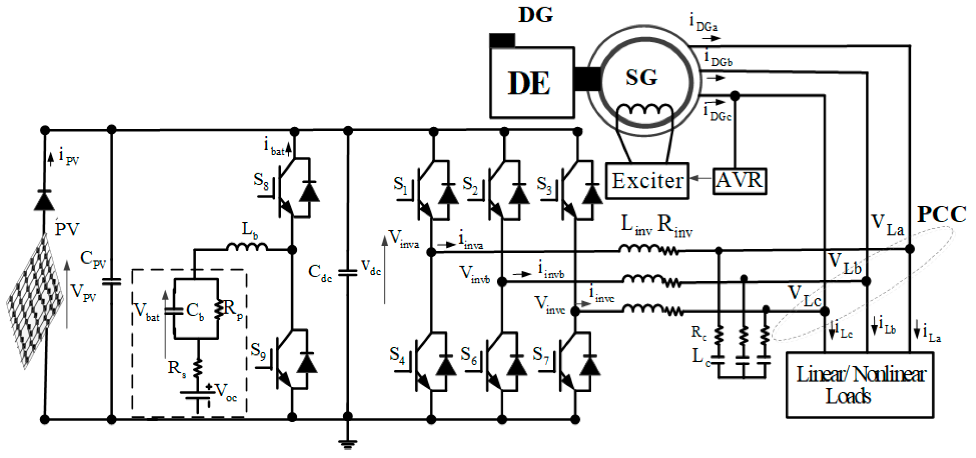
Figure 1 shows a standalone microgrid-based configuration for remote areas. It consists of two energy sources: (1) a fixed speed diesel engine driven synchronous generator, and (2) a SPVA. The DG is connected directly to the PCC and the SPVA is connected directly to the common DC bus and to the PCC through a three-phase voltage source converter (VSC). A lead acid battery pack is connected to the common DC bus through a controller DC-DC buck boost converter. For the proposed configuration, the AC voltage and system frequency are regulated by the governor and automatic voltage regulator (AVR) of the DG. For power quality improvement at the PCC and injection of the generated power from SPVA, the VSC is controlled using a single-phase d-q theory based-sliding mode control strategy. Regarding the power balance in the system and for achieving MPPT from SPVA, an enhanced control strategy based on sliding mode control is used to control the DC-DC buck boost converter. To reduce the ripple voltage due to high switching frequency of VSC, a resistance-inductor-capacitor (RLC) passive filter is employed.
3. Control System
In this section, the developed control strategies for the DC-DC buck boost converter and for three-phase voltage source converter (VSC), are detailed.
3.1. Control of the DC-DC Buck-Boost Converter
As shown in Figure 1 the lead acid battery is connected to the common DC-link through a controlled DC-DC buck-boost converter, which consists of two continuous systems. To balance the power in the system and achieve MPPT from SPVA, sliding mode control (SMC) with boundary layer is used.
3.1.1. Modeling of the DC-DC Buck-Boost Converter
The DC-DC buck-boost converter shown in Figure 1 consists of battery voltage (Vbat) controlled switches (S8 and S9), inductor (Lb), output voltage (Vdc) and a capacitor (Cdc). Depending on the state of the switches, the state-space equations of the DC-DC buck boost converter when the switch is ON are written as:
where R is load resistance, and when the switch is OFF the state-space equations are expressed as:
Replacing, x1 by ibat, and x2 by Vdc, then; , . The state-space equations, which are expressed in (1) and (2) are written as:
where and
where and
The average state-space equation of the DC-DC buck-boost converter is obtained using (3) and (4) as,
where .
3.1.2. Sliding Mode Control for the DC-DC Buck-Boost Converter
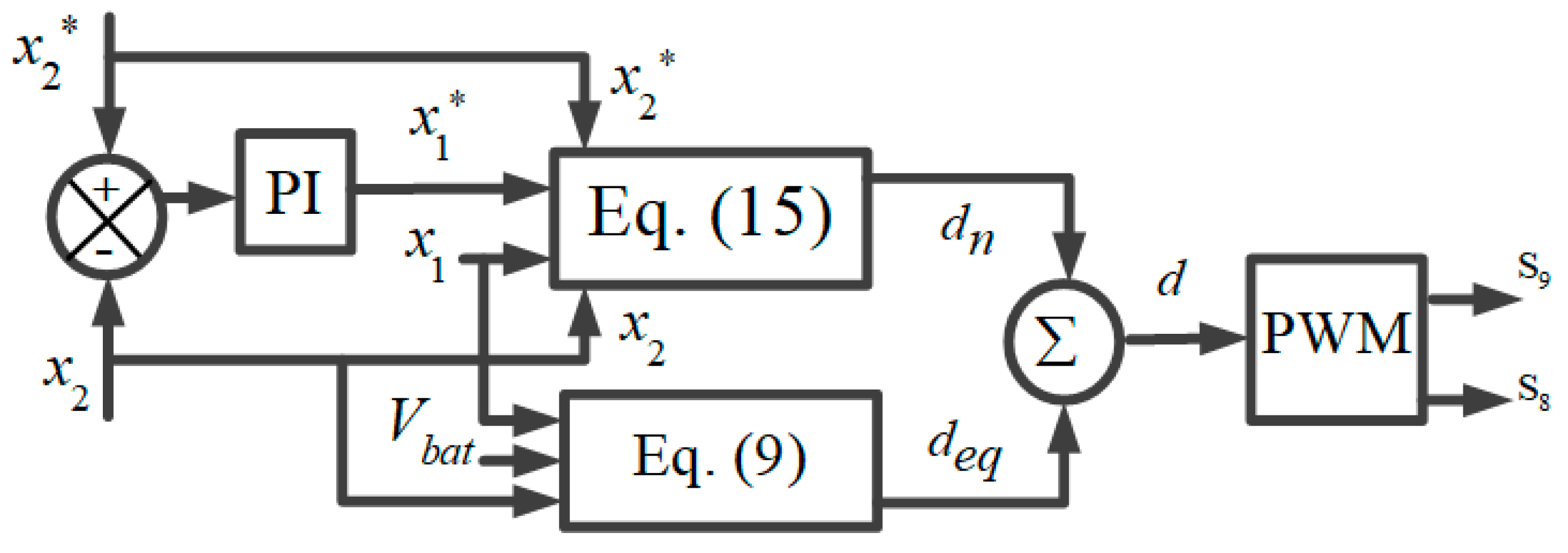
Figure 2 shows the block diagram of the developed control strategy for the DC-DC buck boost converter. Based on (6), the model of the DC-DC buck-boost converter is nonlinear. However, for achieving high dynamic performance during transition with optimal accuracy regulation and robust trajectory tracking in presence of uncertain parameters, the SMC approach is employed. The control design of the general control (d) for the DC-DC buck boost converter is obtained using the following steps:
3.1.3. Selection of the Sliding Surface
The sliding surface (σ) as expressed in (6) is selected to ensure reaching the surface with desiring dynamics of the corresponding sliding motion [28,29,30]:
where β1 and β2 represent the sliding gains and they should be positive.
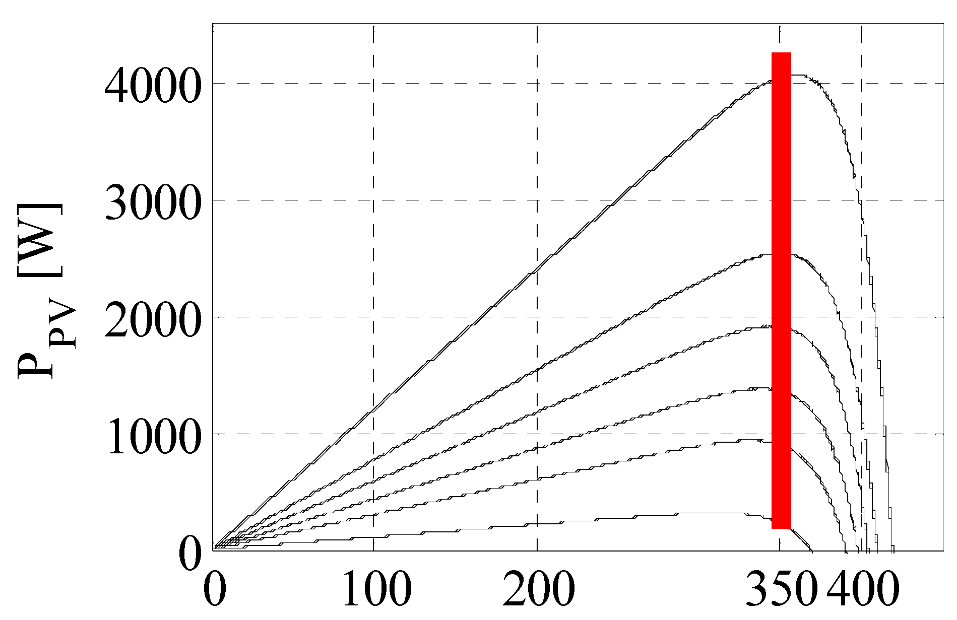
The and denote the battery current and DC-link voltage references, respectively. The value of the DC-link voltage reference is equal to output PV voltage (VPV), which is selected equal to 350 V. As presented in Figure 3, VPV corresponds to the maximum extracted power from the SPVA for different solar irradiations. Therefore, by controlling the DC-link voltage, one can easily extract the maximum of power without using any MPPT method.
3.1.4. Equivalent Control
The structure of the desired control (d) is obtained as:
where represents the nonlinear control and is the equivalent control, which is obtained using (5), (6) and by setting the derivative of (6) to zero as:
By replacing and by their equality, one obtains the following expression as:
3.1.5. Stability Analysis
The objective of the approach using SMC is to ensure the convergence of the operating points to define the sliding boundary. Therefore, for assuring the stability of the control, Lyapunov stability function. According to Lyapunov theorem, a non-linear time variant system is globally and uniformly stable if satisfies the following conditions as [31,32]:
The system is considered asymptotically stable as detailed in (10), the derivative of (11) should be negative:
Replacing (6) and (8) in (12), one gets:
where the and denote the references of the battery current, which represents the output of the PI controller with anti-windup DC link voltage regulator, and DC-link voltage, which is equal to the 350 V, respectively
Substituting terms , , , , and by their equivalences in (12) gives the following expression:
Replacing the parameters , , , , as well as the optimal gains of the SMC and by their value given in Table 1, the first term with negative sign in (14) is larger than the second term. This leads that condition given in (13) is satisfied, which confirms that the system is asymptotically stable.
To ensure the robustness, the second of the desired control , which represents the discontinuous control is written as [35,36,37]:
where is positive control gain.
To reduce the chattering of the control signal, saturation function with boundary conditions is defined as:
where denotes the sliding layer, which is selected between 0.5 and −0.5 [11].
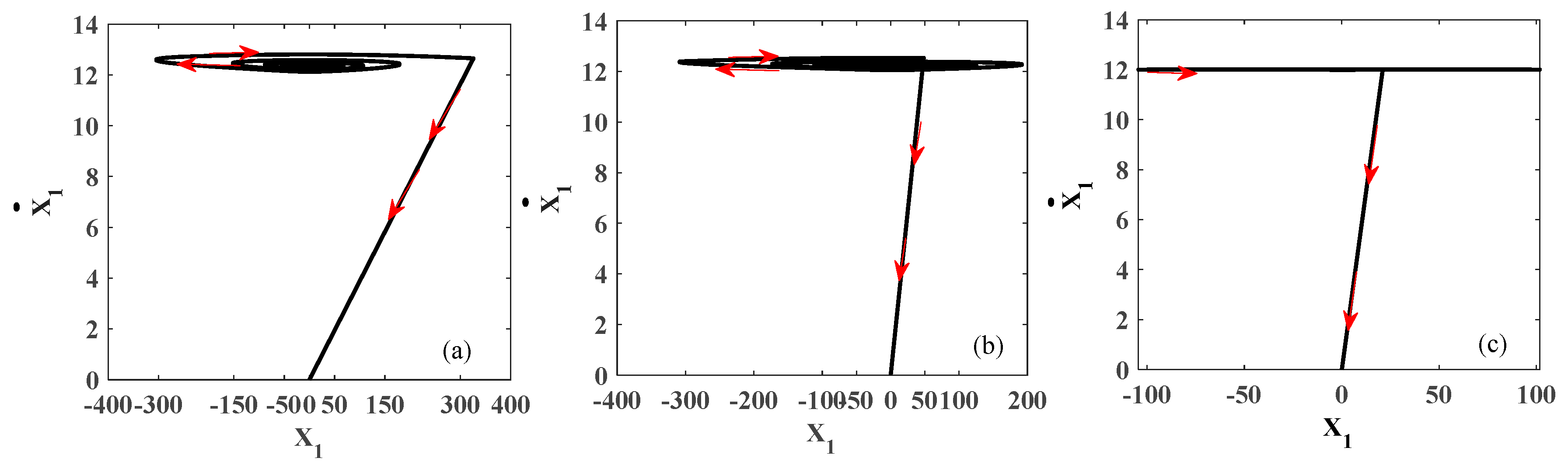
The optimal gains () of the SMC, are selected equal to , and , respectively. One observes in Figure 4c, that based on the optimal values of the signal reaches the origin rapidly.
3.2. Control of Three-Phase Voltage Source Converter
In Figure 5 the single-phase d-q theory-based sliding mode controller for VSC to improve the power quality and inject the generated power from the solar photovoltaic system into PCC, is presented. Regarding the DC link voltage regulation, is ensured by controlling the DC-DC buck boost converter. Inverter voltage () and current (), load current () and voltage are used to determine the inverter voltage references (). The d-q rotating frame and (α-β) stationary frame are employed to transform all time-varying signals to DC quantities with time-invariant.
The rotating angle of d-q frame is calculated using the in-phase and quadrature united vectors as in [18]. The amplitude of the PCC voltage (Vp) is calculated as:
The in-phase unit templates of the PCC voltage, are calaculted as follows:
and the quadrature unit templates of the PCC voltages are expreesed as:
The cosθ and sinθ, are defined as:
The obtained dq-axis load current consist of the fundamentals () and harmonics components ():
Regarding the harmonics (), which are extracted using high pass filter (HPF) represent the output inverter currents, they are transformed into the (α-β) stationary frame., and are used after to determine the reference inverter voltages.
3.2.1. Sliding Mode Current Controller
A sliding mode current controller (SMCC) is proposed for the inner current control loop to achieve high performance during transition with a fast-dynamic response. To design the controller, the following steps are used.
3.2.2. Selecting the Switching Surface
Switching surface for SMCC is selected to ensure fast dynamic response during transition with zero steady-state [38]:
where , and are positive gains. The , represent the obtained errors between measured and reference output VSC currents, which are defined as:
Applying the Kirchhoff current and voltage law at the output of the VSC, one obtains the following expression in stationary (α-β) frame:
where and denote the inductor and resistor of the output filter of VSC.
Using (24), (22) and (23) and its derivative, one obtains the following expression:
The structure of the desired control (, and ), are expressed as:
where , , , and represent the equivalent controls and nonlinear control in the stationary (α-β) frame.
Regarding, the equivalent controls are obtained by set the sliding switching equal to zero:
From (25), one obtains the equivalent controls stationary (α-β) frame:
The nonlinear control is selected equal to:
where represents the controller gain and is positive.
3.2.3. Stability Analysis
The system is considered globally stable only if the derivative of (10) is negative. Using (26) and (22), one gets the following expression:
Equation (28) can be written as:
To determine the sign of (31), one determines first the sign of each term independently. Considering the first term (), which represents the derivative of the reference inverter current, is equal to zero and regarding, that DG ensures the regulation of the voltage at PCC, one assumes that the PCC voltage and the voltage at the output of the VSC are equal, which leads that the second term () being equal to zero, and . As known the integral is always positive, so the sign of the sixth term () is positive. The error between the inverter current and its reference is smaller, so, the fifth term () is smaller than the sixth term. Based on this analysis, one concludes that the sign of is always negative, which implies that the system is asymptotically stable.
4. Results and Discussion
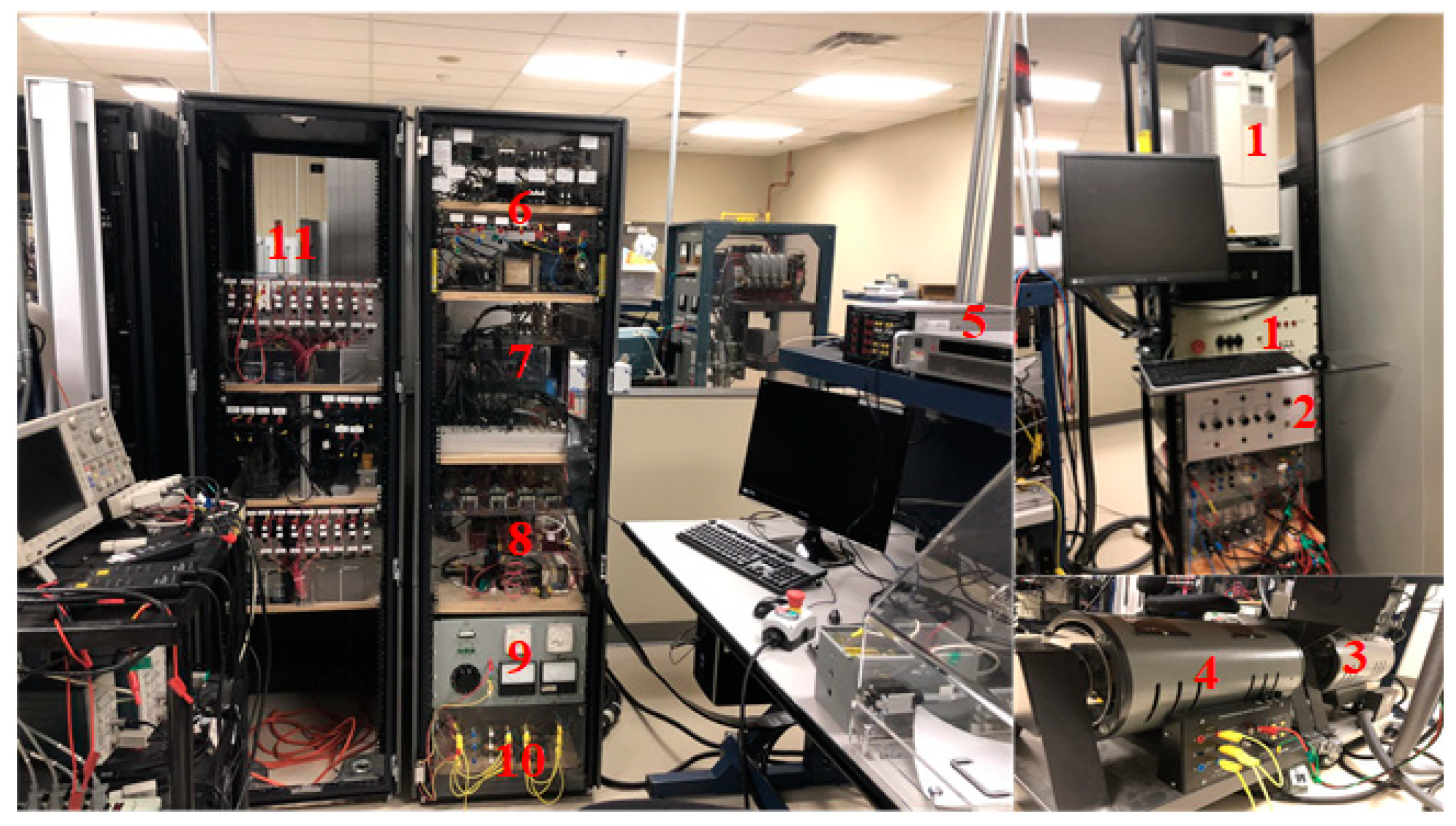
The performance of the developed control strategies for the VSC and DC-DC buck-boost converter, was tested through a simulation using MATLAB/Simulink and in real-time using a hardware prototype. In Figure 6 the hardware prototype of a standalone microgrid is presented. It consists of: (1) ABB drive, (2) synchronizer of DG, (3) induction motor, (4) synchronous generator, (5) SPVA simulator, (6) loads, (7) Protections cards, dSPACE and SEMIKRON power converter, (8) sensors, (9) step down transformer, (10) RC passive filter, and (11) lead acid battery pack.
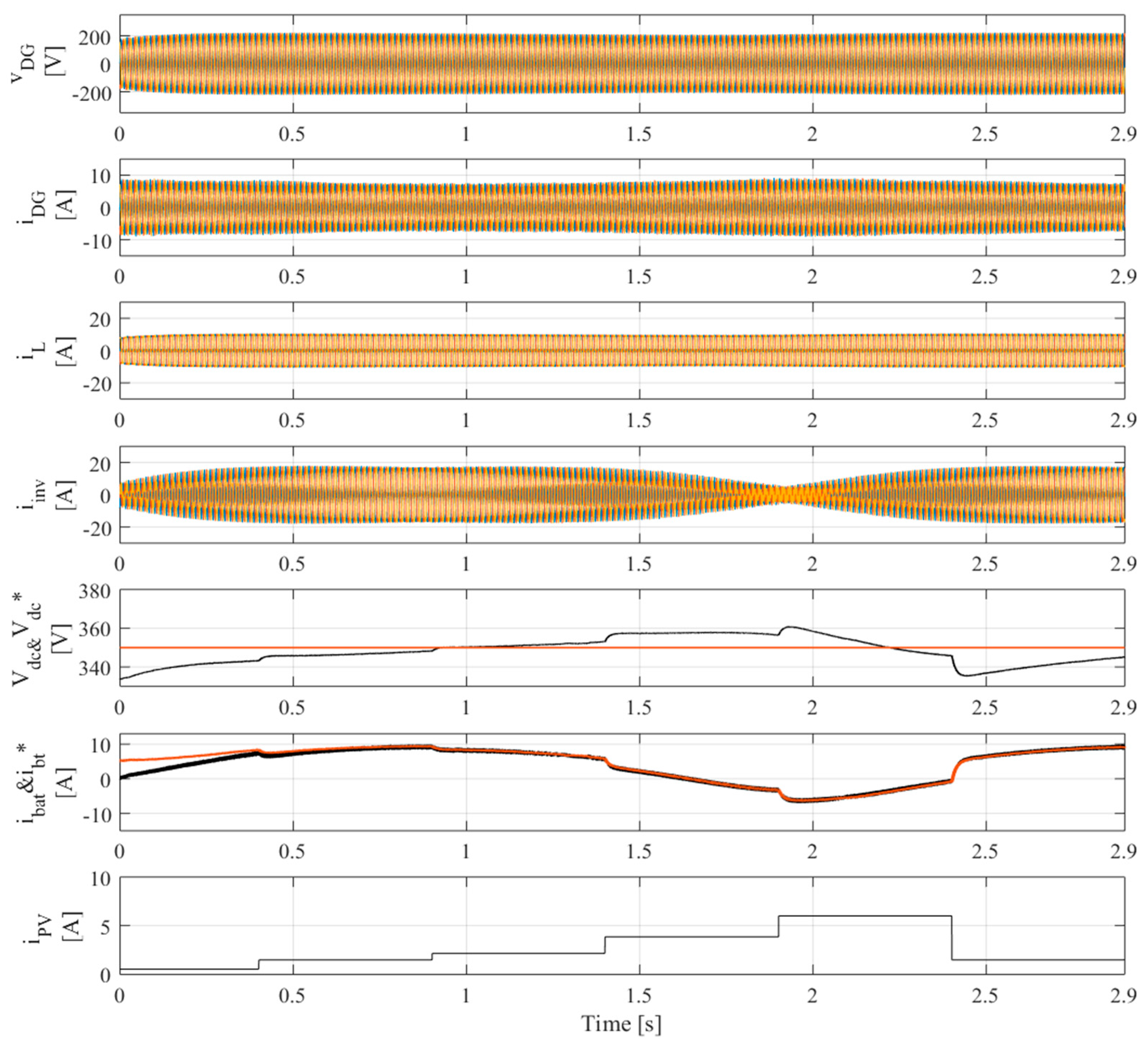
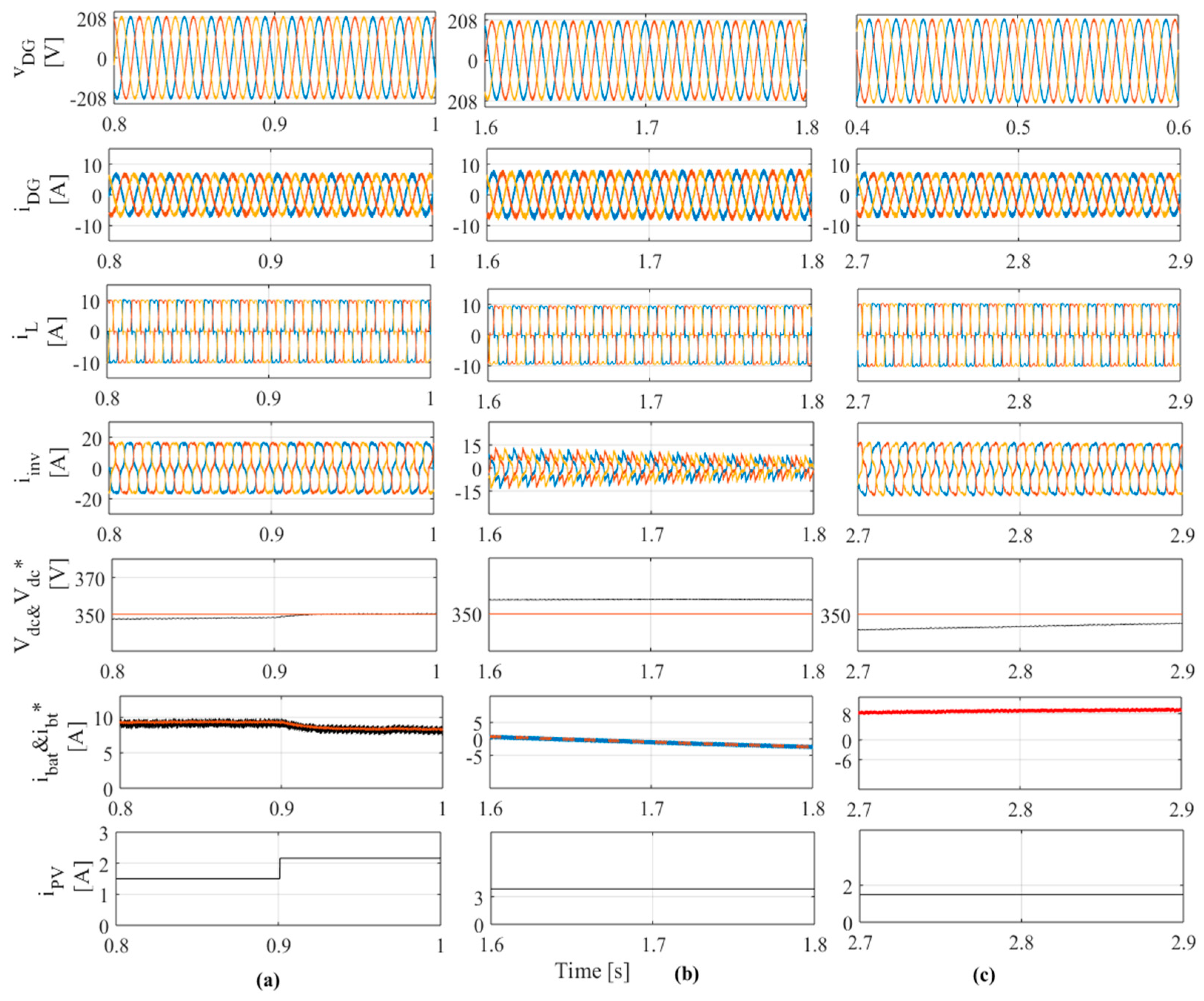
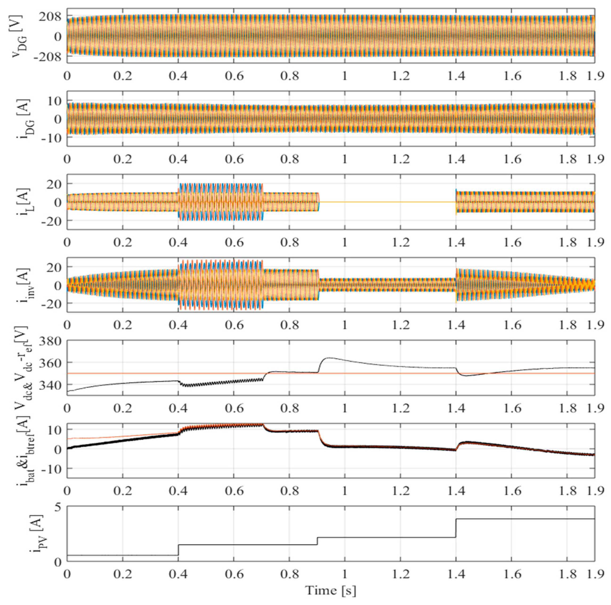
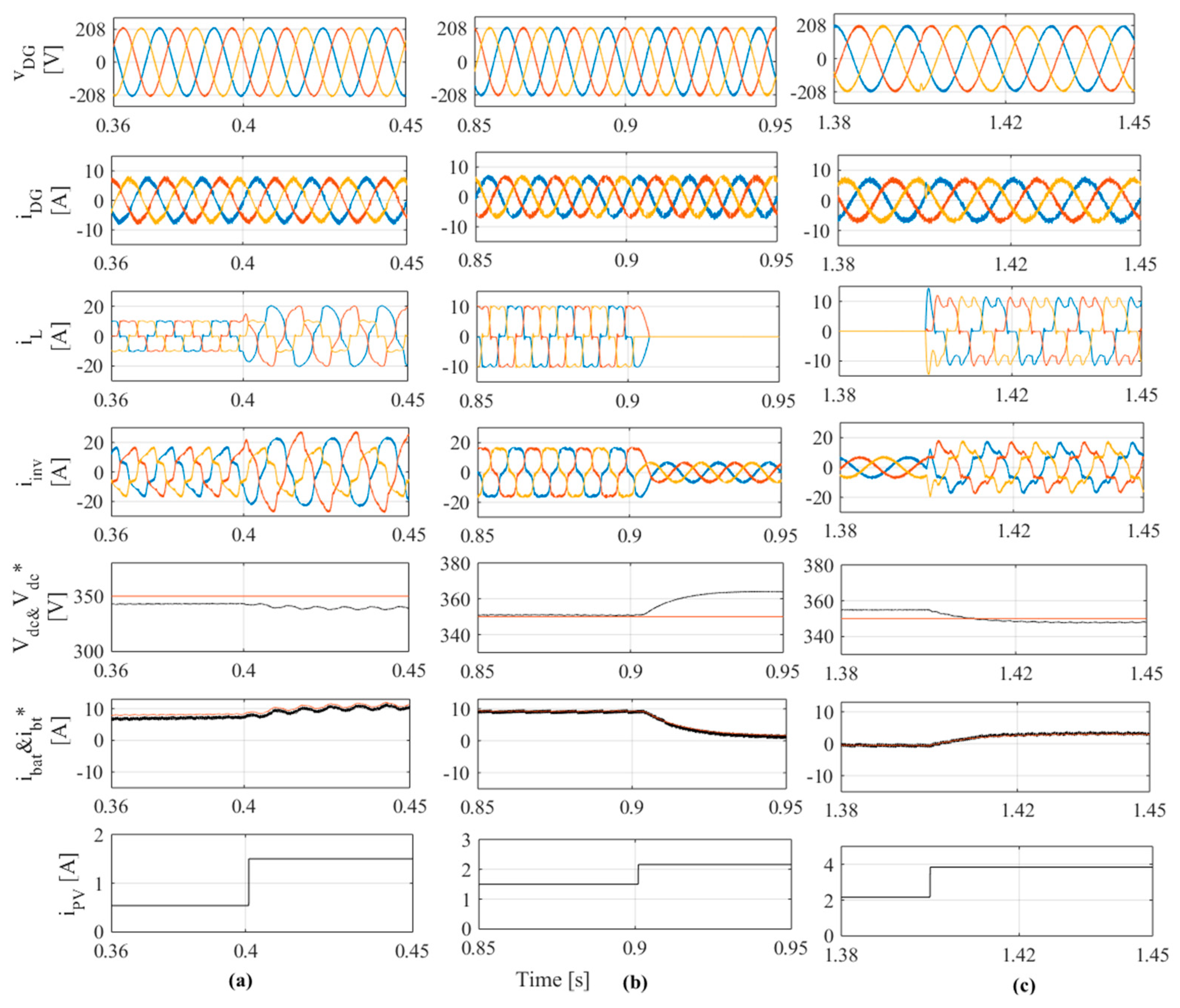
In Figure 7 the dynamic performances of the terminal voltage () and current of synchronous generator, load current , inverter current (), DC-link voltage () and its reference (), battery current () and its reference (), and output SPVA current () are shown. The zoomed waveforms presented in Figure 6 are shown in Figure 8. It is observed that the AC voltage at the PCC and the frequency are regulated at their rated values, which confirms that the governor and the automatic voltage regulator of the DG are working well. One can see clearly in the zoomed waveforms presented in Figure 8a–c, that the DG currents are balanced and sinusoidal, which confirms that the single-phase d-q control-based sliding mode controller performs well in the presence of balanced nonlinear loads. One observes that the DC-link voltage and battery current follow their references during solar irradiation changes, which confirms the robustness of the developed control strategy-based sliding mode control with boundary layer. One observes from the obtained results shown in Figure 8a–c that during transitions when solar irradiation changes the battery current follows its reference, which represents the output of the DC-link voltage regulator without saturation and with zero steady state error. The output SPVA current, which represents the maximum of SPVA current and DC-link voltage varies with variation of solar irradiation as shown in Figure 3, which confirms that it is possible to achieve MPPT without using any MPPT method.
In Figure 9 and Figure 10, the waveforms and the zoomed of terminal voltage () and current of synchronous generator, load current , inverter current (), DC-link voltage () and its reference (), battery current () and its reference (), and output SPVA current (), are presented. To test the performance of the developed control strategies, the system is subjected to severe conditions, such as the presence of balanced and unbalanced nonlinear RL and RC load types as well as during solar irradiation changes. It is observed that in the presence of different loads, the DG current is balanced and sinusoidal.
In addition, DC-DC buck boost can extract the maximum of power from the SPVA and balance the power in the system by charging and discharging the battery, which confirms the robustness of the proposed control strategies based on sliding mode control for the standalone microgrid system. In Figure 11 the harmonics spectrum of the PCC voltage, DG current, and load currents when RL and RC nonlinear load, are presented. It is observed that in the both cases the total harmonic distortion (THD) of the load current is high (THD = 24% with RL nonlinear and 27% with RC nonlinear load), and the THD of the source current, which represents in the standalone microgrid shown in Figure 1, the output current of the DG is less than 5% (THD = 4.07% with RL nonlinear and 4.28% with RC nonlinear load). This respects the norms of IEEE standard 519-1992. One sees clearly that the THD of the PCC voltage is less than to 5% in the presence of the both nonlinear loads, which confirms the robustness of the proposed Single-phased d-q theory-based on SMC for power quality improvement.
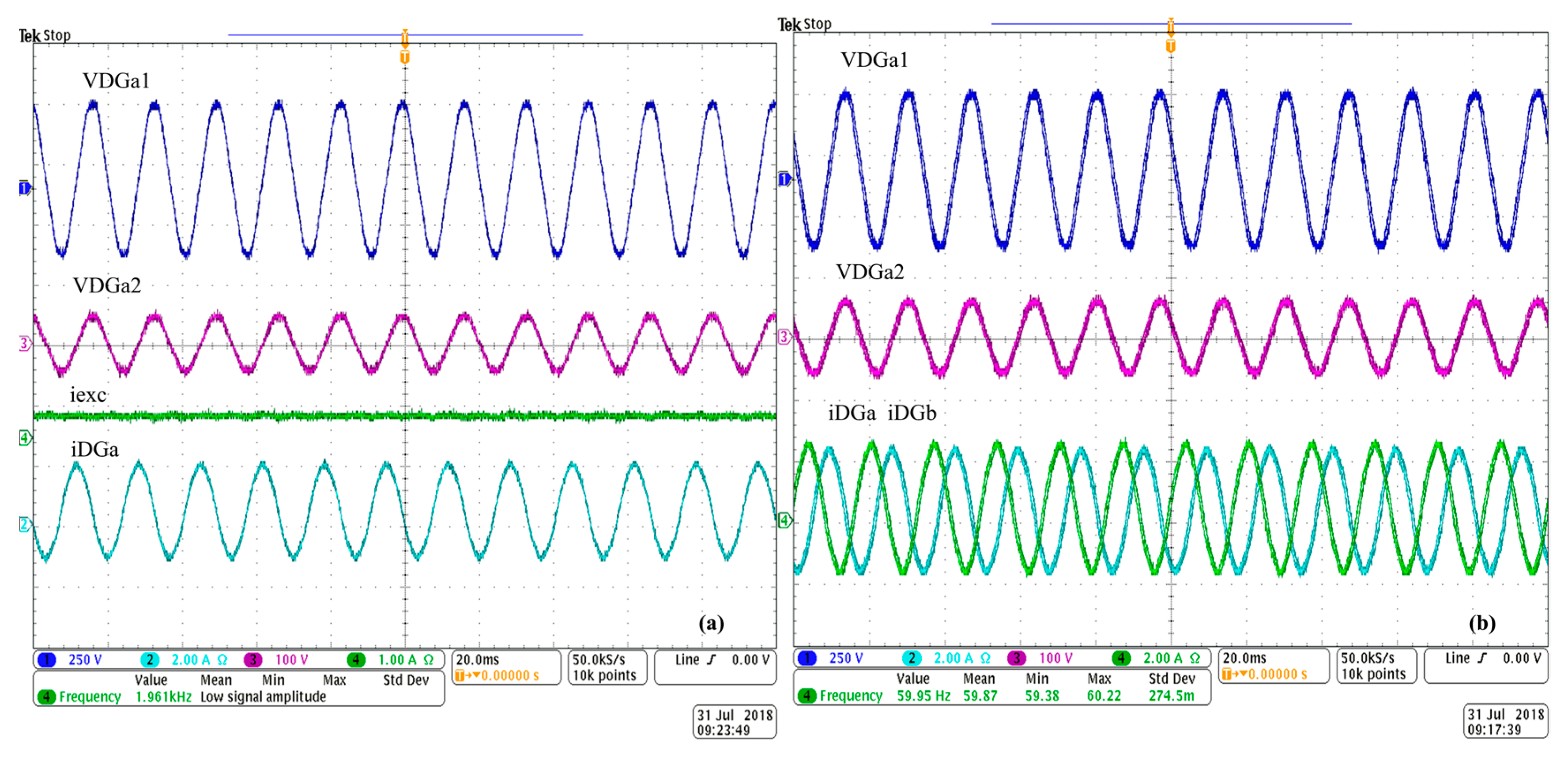
In Figure 12a,b, the steady-state performance of the DG is presented. One observes that the terminal voltage before step down transformer () and at the secondary of transformer are regulated constant and sinusoidal. Seeing that DG operates at fixed speed, excitation current () is constant, one can observe that the system frequency is constant, and the stator current are sinusoidal.
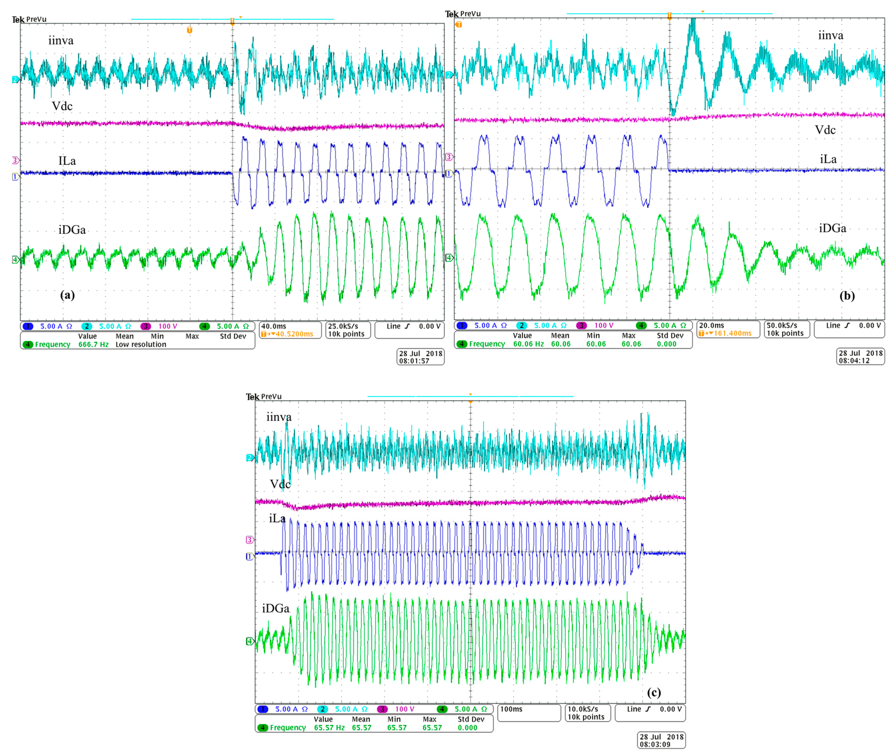
To test the performance of the developed control strategies-based sliding mode control, the system is subjected to load variations as presented in Figure 13a–c. It is observed in Figure 13a that at t = 0.2 ms the system is subjected to a sudden variation of nonlinear load type RL. One observes that VSC operates as a shunt active filter, and it compensates the harmonics and balances the DG current. One observes that the DC-link voltage is well regulated. In Figure 13b, the system is subjected to sudden switching off the nonlinear load type RC at t = 0.2 ms. It is observed that the VSC acts as a shunt filter and compensates the harmonics as well as balances the DG current. One sees that DC-link voltage is increased when the load is switched off, because the battery starts charging. In Figure 13c, the system is subjected to sudden switching on and off at t = 0.1 ms and at t = 1 s, and one observes that the DC-link voltage is well regulated and the VSC acts as a shunt active filter and injects the power into the PCC. One sees clearly in Figure 13a–c, that the both developed control strategies perform well in the presence of severe conditions.
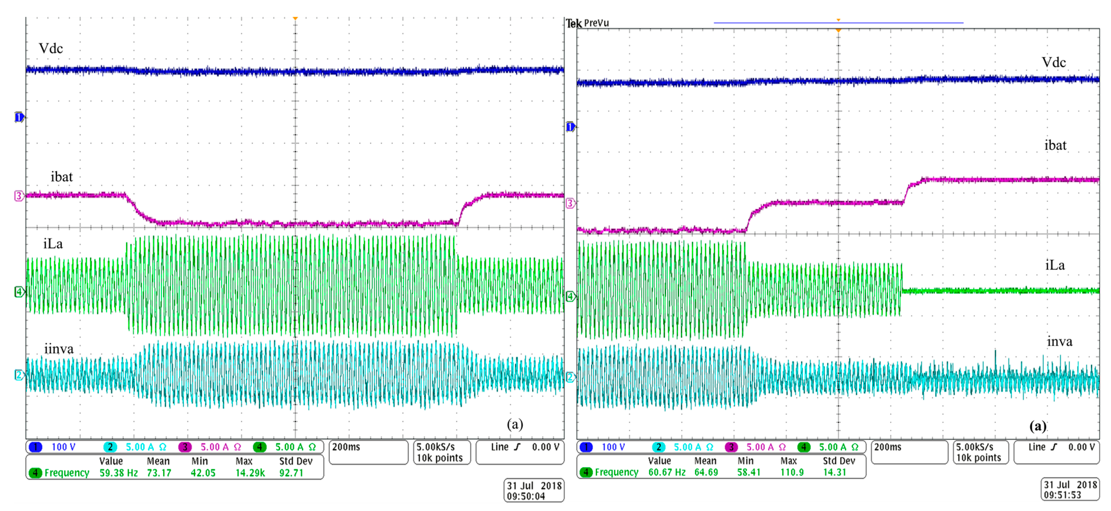
The performance of DC-link voltage (), battery current (), load current () and inverter current (), are presented in Figure 14a,b. It is observed that the DC-link voltage is regulated at their rated value when the system is subjected to load variations at t = 0.4 s and t = 0.8 s in Figure 14a, and at t = 0.3 s, and t = 0.8 s in Figure 14b. One observes that the battery current varies with load variation, balancing the power in the system. This leads that the system performing well during all conditions, which confirms the robustness of the developed control strategy-based sliding mode control.
5. Conclusions
In this paper, a real-time implementation of robust control strategies based on sliding mode control for a standalone microgrid has been presented. Single-phase d-q theory based on sliding mode controller for fast inner control loop for three-phase voltage source converter was studied and analyzed. Furthermore, modeling and stability analyses are given in detail. Sliding mode control with boundary layer is developed for DC-DC buck boost. It has been proven that the developed control strategies perform well during severe conditions, such as load variation and solar irradiation changes. The obtained simulation, as well as, experimental results show satisfactory performance.
Author Contributions
This paper was a collaborative effort between the authors. The authors under supervision of A.C. contributed collectively in all steps of this research work including validation in real-time.
Funding
This research received no external funding.
Acknowledgments
Validation in real time is realized at École de technologie supérieure in laboratory of Power Electronics and Industrial Control Research Group (GREPCI), at Montreal, Quebec, Canada.
Conflicts of Interest
The authors declare no conflict of interest.
References
- Kaldellis, J.K. Stand-Alone and Hybrid Wind Energy Systems: Technology, Energy Storage and Applications, 1st ed.; Woodhead Publishing: Cambridge, MA, USA, 2010; pp. 7–10. [Google Scholar]
- Sreekumar, P.; Khadkikar, V. Adaptive power management strategy for effective volt–ampere utilization of a photovoltaic generation unit in standalone microgrids. IEEE Trans. Ind. Appl. 2018, 54, 1784–1792. [Google Scholar] [CrossRef]
- Rezkallah, M.; Chandra, A.; Tremblay, M.; Ibrahim, H. Experimental Implementation of an APC with Enhanced MPPT for Standalone Solar Photovoltaic based Water Pumping Station. IEEE Trans. Sustain. Energy 2018. [Google Scholar] [CrossRef]
- Shi, R.; Zhang, X. VSG-Based dynamic frequency support control for autonomous PV–diesel microgrids. Energies 2018, 11, 1814. [Google Scholar] [CrossRef]
- Rezkallah, M.; Singh, S.; Chandra, A.; Saad, M.; Singh, B.; Tremblay, M.; Geng, H. Real-time hardware testing, control and performance analysis of hybrid cost-effective wind-PV-diesel standalone power generation system. In Proceedings of the 2017 IEEE Industry Applications Society Annual Meeting, Cincinnati, OH, USA, 1–5 October 2017; pp. 1–8. [Google Scholar]
- Gan, L.K.; Shek, J.K.; Mueller, M.A. Analysis of Tower Shadow Effects on Battery Lifetime in Standalone Hybrid Wind-Diesel-Battery Systems. IEEE Trans. Ind. Electron. 2017, 64, 6234–6244. [Google Scholar] [CrossRef] [Green Version]
- Nguyen, N.H.; Nguyen-Duc, H.; Nakanishi, Y. Optimal sizing of energy storage devices in wind-diesel systems considering load growth uncertainty. IEEE Trans. Ind. Appl. 2018, 54, 1983–1991. [Google Scholar] [CrossRef]
- Rezkallah, M.; Chandra, A.; Rousse, D.R.; Ibrahim, H.; Ilinca, A.; Ramdenee, D. Control of small-scale wind/diesel/battery hybrid standalone power generation system based on fixed speed generators for remote areas. In Proceedings of the IEEE, IECON 2016, Florence, Italy, 23–26 October 2016; pp. 4060–4065. [Google Scholar]
- Kamal, E.; Aitouche, A.; Oueidat, M. Fuzzy fault-tolerant control of wind-diesel hybrid systems subject to sensor faults. IEEE Trans. Sustain. Energy 2013, 4, 857–866. [Google Scholar] [CrossRef]
- Adefarati, T.; Bansal, R.C.; Justo, J.J. Techno-economic analysis of a PV–wind–battery–diesel standalone power system in a remote area. J. Eng. 2017, 13, 740–744. [Google Scholar] [CrossRef]
- Rezkallah, M.; Hamadi, A.; Chandra, A.; Singh, B. Design and implementation of active power control with improved P&O method for wind-PV-battery-based standalone generation system. IEEE Trans. Ind. Electron. 2018, 65, 5590–5600. [Google Scholar]
- Rezkallah, M.; Chandra, A.; Singh, B.; Singh, S. Microgrid: Configurations, Control and Applications. IEEE Trans. Smart Grid 2017. [Google Scholar] [CrossRef]
- Wies, R.W.; Johnson, R.A.; Agrawal, A.N.; Chubb, T.J. Simulink model for economic analysis and environmental impacts of a PV with diesel-battery system for remote villages. IEEE Trans. Power Syst. 2005, 20, 692–700. [Google Scholar] [CrossRef]
- Nejabatkhah, F.; Li, Y.W.; Nassif, A.B.; Kang, T. Optimal design and operation of a remote hybrid microgrid. CPSS Trans. Power Electron. Appl. 2018, 3, 3–13. [Google Scholar] [CrossRef]
- Mokhtar, M.; Marei, M.I.; El-Sattar, A.A. An adaptive droop control scheme for DC microgrids integrating sliding mode voltage and current controlled boost converters. IEEE Trans. Smart Grid 2017. [Google Scholar] [CrossRef]
- Yazici, İ.; Yaylaci, E.K. Fast and robust voltage control of DC–DC boost converter by using fast terminal sliding mode controller. IET Power Electron. 2016, 9, 120–125. [Google Scholar] [CrossRef]
- Chincholkar, S.H.; Jiang, W.; Chan, C.Y. An improved PWM-based sliding-mode controller for a DC-DC cascade boost converter. IEEE Trans. Circ. Syst. II Express Br. 2017. [Google Scholar] [CrossRef]
- Singh, B.; Chandra, A.; Al-Haddad, K. Power Quality: Problems and Mitigation Techniques; John Wiley & Sons: Hoboken, NJ, USA, 2014; pp. 2–10. [Google Scholar]
- Dong, H.; Yuan, S.; Han, Z.; Ding, X.; Ma, S.; Hana, X. A Comprehensive strategy for power quality improvement of multi-inverter-based microgrid with mixed loads. IEEE Access 2018, 6, 30903–30916. [Google Scholar] [CrossRef]
- Ko, H.S.; Jang, M.S.; Ryu, K.S.; Kim, D.J.; Kim, B.K. Supervisory Power Quality Control Scheme for a Grid-Off Microgrid. IEEE Trans. Sustain. Energy 2018, 9, 1003–1010. [Google Scholar] [CrossRef]
- Kesler, M.; Ozdemir, E. Synchronous-reference-frame-based control method for UPQC under unbalanced and distorted load conditions. IEEE Trans. Ind. Electron. 2011, 58, 3967–3975. [Google Scholar] [CrossRef]
- García, P.; García, C.A.; Fernández, L.M.; Llorens, F.; Jurado, F. ANFIS-based control of a grid-connected hybrid system integrating renewable energies, hydrogen and batteries. IEEE Trans. Ind. Inform. 2014, 10, 1107–1117. [Google Scholar] [CrossRef]
- Seifi, K.; Moallem, M. An adaptive PR controller for synchronizing grid-connected inverters. IEEE Trans. Ind. Electron. 2018. [Google Scholar] [CrossRef]
- Wang, T.; Fei, J. Adaptive neural control of active power filter using fuzzy sliding mode controller. IEEE Access 2016, 4, 6816–6822. [Google Scholar] [CrossRef]
- Fei, J.; Chu, Y.; Hou, S. A backstepping neural global sliding mode control using fuzzy approximator for three-phase active power filter. IEEE Access 2017, 5, 16021–16032. [Google Scholar] [CrossRef]
- Cao, D.; Fei, J. Adaptive fractional fuzzy sliding mode control for three-phase active power filter. IEEE Access 2016, 4, 6645–6651. [Google Scholar] [CrossRef]
- Guzman, R.; de Vicuña, L.G.; Morales, J.; Castilla, M.; Miret, J. Model-based control for a three-phase shunt active power filter. IEEE Trans. Ind. Electron. 2016, 63, 3998–4007. [Google Scholar] [CrossRef]
- Tsai, J.F.; Chen, Y.P. Sliding mode control and stability analysis of buck DC-DC converter. Int. J. Electron. 2007, 94, 209–222. [Google Scholar] [CrossRef]
- Reitz, M.A.; Wang, X. Robust Sliding Mode Control of Buck-Boost DC-DC Converters. In Proceedings of the ASME 2016 Dynamic Systems and Control Conference, MN, USA, 12–14 October 2016. [Google Scholar]
- Guldemir, H. Modeling and sliding mode control of DC-DC buck-boost converter. In Proceedings of the 6th International Advanced Technologies Symposium (IATS’11), Elazığ, Turkey, 16–18 May 2011; pp. 475–480. [Google Scholar]
- Slotine, J.J.; Li, W. Applied nonlinear Control; Prentice Hall: Englewood Cliffs, NJ, USA, 1991; pp. 105–116. [Google Scholar]
- Gavagsaz-Ghoachani, R.; Phattanasak, M.; Martin, J.P.; Pierfederici, S.; Nahid-Mobarakeh, B.; Riedinger, P. A lyapunov function for switching command of a DC–DC power converter with an LC input filter. IEEE Trans. Ind. Appl. 2017, 53, 5041–5050. [Google Scholar] [CrossRef]
- Rezkallah, M.; Sharma, S.K.; Chandra, A.; Singh, B.; Rousse, D.R. Lyapunov function and sliding mode control approach for the solar-PV grid interface system. IEEE Trans. Ind. Electron. 2017, 64, 785–795. [Google Scholar] [CrossRef]
- Rezkallah, M.; Hamadi, A.; Chandra, A.; Singh, B. Real-time HIL implementation of sliding mode control for standalone system based on PV array without using dumpload. IEEE Trans. Sustain. Energy. 2015, 6, 1389–1398. [Google Scholar] [CrossRef]
- Wai, R.J.; Shih, L.C. Design of voltage tracking control for DC–DC boost converter via total sliding-mode technique. IEEE Trans. Ind. Electron. 2011, 58, 2502–2511. [Google Scholar] [CrossRef]
- Saghafinia, A.; Ping, H.W.; Uddin, M.N. Fuzzy sliding mode control based on boundary layer theory for chattering-free and robust induction motor drive. Int. J. Adv. Manuf. Technol. 2014, 71, 57–68. [Google Scholar] [CrossRef]
- Wang, W.J.; Chen, J.Y. A new sliding mode position controller with adaptive load torque estimator for an induction motor. IEEE Trans. Energy Convers. 1999, 14, 413–418. [Google Scholar] [CrossRef]
- Boum, A.T.; Djidjio Keubeng, G.B.; Bitjoka, L. Sliding mode control of a three-phase parallel active filter based on a two-level voltage converter. Syst. Sci. Control Eng. 2017, 5, 535–543. [Google Scholar] [CrossRef] [Green Version]
Figure 1.
The standalone microgrid configuration under study.

Figure 2.
Control of the DC-DC buck boost converter.

Figure 3.
with fixed temperature and solar irradiation change.

Figure 4.
Diagram of with: (a) , and , (b) , and , and (c) , and .

Figure 5.
Single-phased d-q theory-based on SMC.
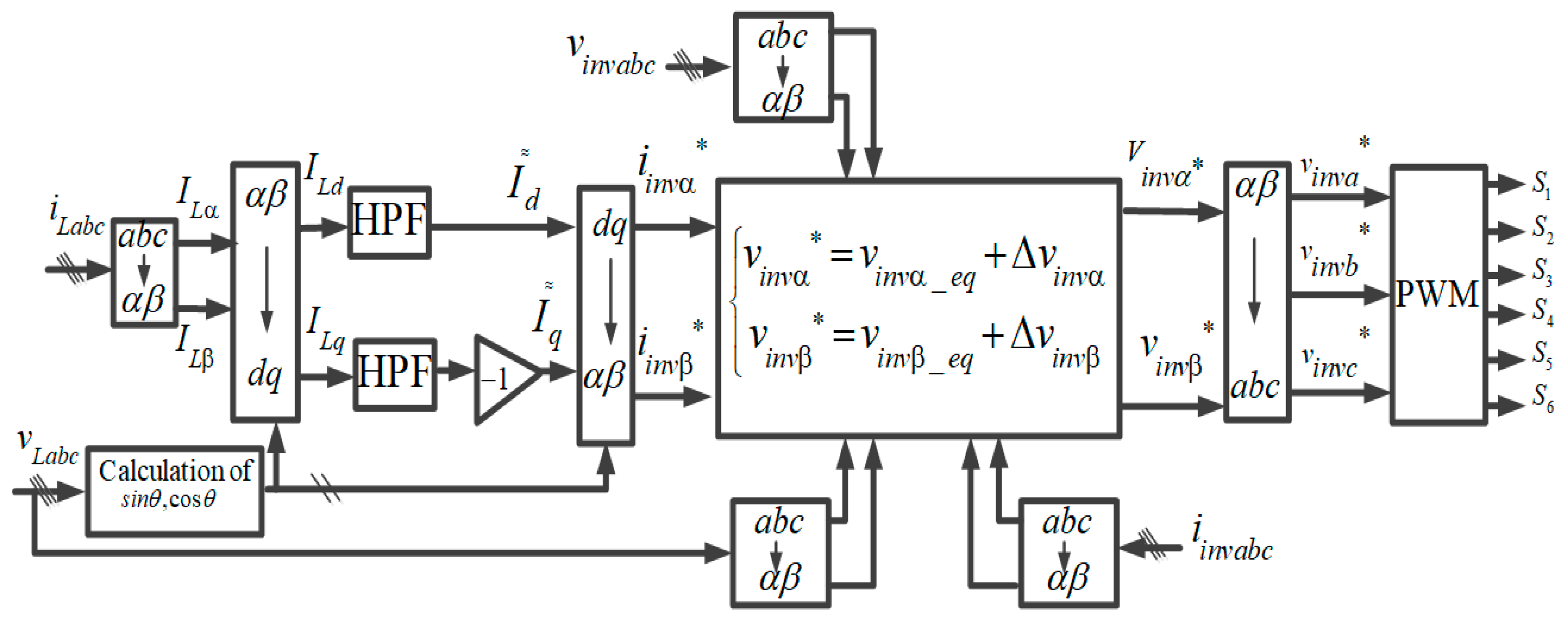
Figure 6.
Hardware prototype of a standalone microgrid.

Figure 7.
Dynamic performance under presence of balanced RL nonlinear load and solar irradiation change.
Figure 7.
Dynamic performance under presence of balanced RL nonlinear load and solar irradiation change.

Figure 8.
Zoom of waveforms of Figure 6 between (a) t = 0.8 s to t = 1 s, (b) t = 1.6 s to t = 1.8 s and (c) between t = 2.7 s to t = 2.9 s.
Figure 8.
Zoom of waveforms of Figure 6 between (a) t = 0.8 s to t = 1 s, (b) t = 1.6 s to t = 1.8 s and (c) between t = 2.7 s to t = 2.9 s.

Figure 9.
Dynamic performance under presence of balanced and unbalanced nonlinear load (diode bridge +RL and RC loads) and solar irradiation change.
Figure 9.
Dynamic performance under presence of balanced and unbalanced nonlinear load (diode bridge +RL and RC loads) and solar irradiation change.

Figure 10.
Zoom of the waveforms of Figure 6 between (a) t = 0.8s to t = 1 s, (b) t = 1.6 s to t = 1.8 s and (c) between t = 2.7 s to t = 2.9 s.
Figure 10.
Zoom of the waveforms of Figure 6 between (a) t = 0.8s to t = 1 s, (b) t = 1.6 s to t = 1.8 s and (c) between t = 2.7 s to t = 2.9 s.

Figure 11.
Harmonics spectrum of the PCC voltage, DG current and load current with RL and RC nonlinear loads.
Figure 11.
Harmonics spectrum of the PCC voltage, DG current and load current with RL and RC nonlinear loads.

Figure 12.
Steady-state performance in the presence of linear loads.

Figure 13.
Dynamic performance under sudden variation of: (a) balanced RL nonlinear load, (b) balanced RC nonlinear load, and (c) under switching on and off of RL nonlinear load.
Figure 13.
Dynamic performance under sudden variation of: (a) balanced RL nonlinear load, (b) balanced RC nonlinear load, and (c) under switching on and off of RL nonlinear load.

Figure 14.
Dynamic performance under fixed solar irradiation and load change. (a) sudden increase and decrease of load; and (b) sudden decrease and disconnect of load.
Figure 14.
Dynamic performance under fixed solar irradiation and load change. (a) sudden increase and decrease of load; and (b) sudden decrease and disconnect of load.


Table 1.
System parameters.
| Parameters | Value | Parameters | Value |
|---|---|---|---|
| 208 V | , , | 0.1, 25 | |
| 60 Hz | VSC | 10 kHz | |
| 350 V | 1000 µF | ||
| 100 µF | 5 mH | ||
| 1.5 mH | 0.01 Ω | ||
| DC-DC Converter | 10 kHz | 5 Ω | |
| 0.001, 0.8 and 5 | 10 µF |
© 2018 by the authors. Licensee MDPI, Basel, Switzerland. This article is an open access article distributed under the terms and conditions of the Creative Commons Attribution (CC BY) license (http://creativecommons.org/licenses/by/4.0/).
Share and Cite
MDPI and ACS Style
Benhalima, S.; Miloud, R.; Chandra, A. Real-Time Implementation of Robust Control Strategies Based on Sliding Mode Control for Standalone Microgrids Supplying Non-Linear Loads. Energies 2018, 11, 2590. https://doi.org/10.3390/en11102590
AMA Style
Benhalima S, Miloud R, Chandra A. Real-Time Implementation of Robust Control Strategies Based on Sliding Mode Control for Standalone Microgrids Supplying Non-Linear Loads. Energies. 2018; 11(10):2590. https://doi.org/10.3390/en11102590
Chicago/Turabian StyleBenhalima, Seghir, Rezkallah Miloud, and Ambrish Chandra. 2018. "Real-Time Implementation of Robust Control Strategies Based on Sliding Mode Control for Standalone Microgrids Supplying Non-Linear Loads" Energies 11, no. 10: 2590. https://doi.org/10.3390/en11102590
Note that from the first issue of 2016, this journal uses article numbers instead of page numbers. See further details here.