Control-Loop-Based Impedance Enhancement of Grid-Tied Inverters for Harmonic Suppression: Principle and Implementation


College of Mechatronics Engineering and Automation, Shanghai University, Shanghai 200444, China
*
Author to whom correspondence should be addressed.
Energies 2018, 11(11), 2874; https://doi.org/10.3390/en11112874
Submission received: 10 September 2018
/
Revised: 10 October 2018
/
Accepted: 18 October 2018
/
Published: 23 October 2018
(This article belongs to the Special Issue Power Quality in Microgrids Based on Distributed Generators)
Abstract
:To understand different control loops that have been proposed to improve the quality of current into grid from the perspective of output impedance, control-loop-based output impedance enhancement of grid-tied inverters for harmonic suppression is proposed in this paper. The principle and generalized control loop deduction are presented for reshaping the output impedance. Taking a traditional LCL (Inductor-Capacitor-Inductor)-type inverter with dual-loop control as an example, different kinds of control loop topologies are derived step by step and further optimized for the implementation of the proposed principle. Consequently, the improved control consists of a filtering-capacitor voltage loop, and a grid current loop is found which can remove the existing inner capacitor current loop and therefore simplify the control. Finally, the effectiveness of the proposed control method is compared with the existing method and both are verified by simulations and experiments.
1. Introduction
This paper considers the suppression of current harmonics from the perspective of output impedance reshaping. In this section, the background of harmonic suppression, literature review, formulation of the problem of interest for this investigation, scope and contribution of this study, and organization of the paper are provided.
1.1. Background and Significance
With the wide application of power-electronics-based distributed generator equipment, the quality of current into grid is partly polluted with the harmonics caused by the process of switching and the distorted grid voltage [1]. The loss on the cables will increase and some sensitive loads will work abnormally or even break if large harmonic contents of current exist, leading to the low economy of a power system. Therefore, to suppress the current harmonics as well as to achieve the goal of grid-tied requirements for inverters, different kinds of schemes for harmonic suppression have been proposed, including different regulators, topologies, and control loops [2].
1.2. Literature Review
Originally, the L-type grid-tied inverter is usually employed in a distributed generation system with a single grid-current feedback control loop. To satisfy the grid-tied requirements on the harmonics current, a large inductor is generally adopted to mainly suppress the harmonics at the switching frequency. However, the scale of the inverters is large and the effect of harmonic suppression is not sufficient. Therefore, to reduce the scale of inverters as well as achieve a better effect on suppressing current harmonics, an LCL filter is employed [3]. However, as the LCL filter has a resonance peak, the inverter will become unstable if the grid voltage or the inverter has an excitation source at the resonant frequency. To damp the resonant peak, the dual-loop control strategy with capacitor current and grid current has been proposed [4]. The positive resonance peak is compensated by a negative resonance peak which is introduced though an additional compensator [5,6]. However, since the capacitor current contains a large amount of high-frequency harmonics, it is difficult to compensate them accurately. Therefore, instead of using a capacitor current, the weighted average current flowing through the two inductors of an LCL filter is used. This method is a split formation of capacitor current because the capacitor current is equal to the difference of an inverter-side current and grid-side current for an LCL filter [7,8].
Besides the harmonics caused by switches, the background harmonics of grid voltage also affect the grid current [9,10]. To compensate the harmonics in the grid voltage, the grid voltage is directly feedforward (FF), i.e., an equivalent voltage source which has the same magnitude and phase with grid voltage is generated to attenuate the impact of grid voltage disturbance. This method is called the partial feedforward control strategy. It is more suitable for the L-type structure, although for the LCL-type structure, due to the role of the capacitor, partial feedforward control cannot fully compensate the background harmonics of grid voltage [11,12]. The magnitude and phase of the generated equivalent voltage will not be equal to the grid voltage through an LCL filter if partial feedforward control strategy is used. Therefore, the coefficient of feedforward should be modified to get full compensation, that is, a full feedforward control strategy [13]. Other control loops, such as in [14,15], which employ the combination of current feedback and grid voltage feedforward also achieve the effect of suppressing the current harmonics. In addition, some advanced control algorithms such as repetitive control and the adjoint method can be taken into consideration for harmonic suppression [16,17].
1.3. Formulation of the Problem of Interest for This Study
It is necessary that the guideline of harmonic suppression from the perspective of reshaping output impedance should be summarized since the different kinds of control loops which have been proposed in previous literatures are intrinsically enhancing the output impedance. Generally, the equivalent model of grid-tied inverter systems is equal to a current source in parallel with an output impedance [18]. If the output impedance is large enough within the control bandwidth, the current source will become as ideal as possible. Therefore, based on the idea of infinite output impedance enhancement, this paper investigates the principle regarding reshaping the output impedance and optimizing the control loops.
1.4. Scope and Contribution of This Paper
In this paper, through summarizing the prior different control loops, the concept of output impedance enhancement is put forward, thus providing an understanding of different control loops. An optimized control loop is derived from the grid voltage feedforward control strategy, which can remove the existing inner capacitor current loop and therefore simplify the control loop. Meanwhile, the capability of output impedance enhancement is identical to the grid voltage feedforward control strategy. Besides, the cost of the system is reduced and its practical implementation is more convenient.
1.5. Organization of the Mauscript
The rest of this paper is organized as follows: by reshaping the output impedance based on the concept of output impedance enhancement, the grid voltage feedback and grid current feedback methods of reshaping output impedance are obtained in Section 2. The impact of two basic methods on output impedance enhancement is analyzed in detail in Section 3. To simplify the control loop for the convenience of realization, a method of splitting is adopted to optimize the grid voltage feedforward control loop. Then, a novel control loop is proposed in Section 4. The correctness of the proposed control loop is verified in simulation and experiment in Section 5. Finally, a conclusion is made in Section 6.
2. Principle of Control-Loop-Based Impedance Enhancement
2.1. Reshaping Principle Based on Output Impedance Models
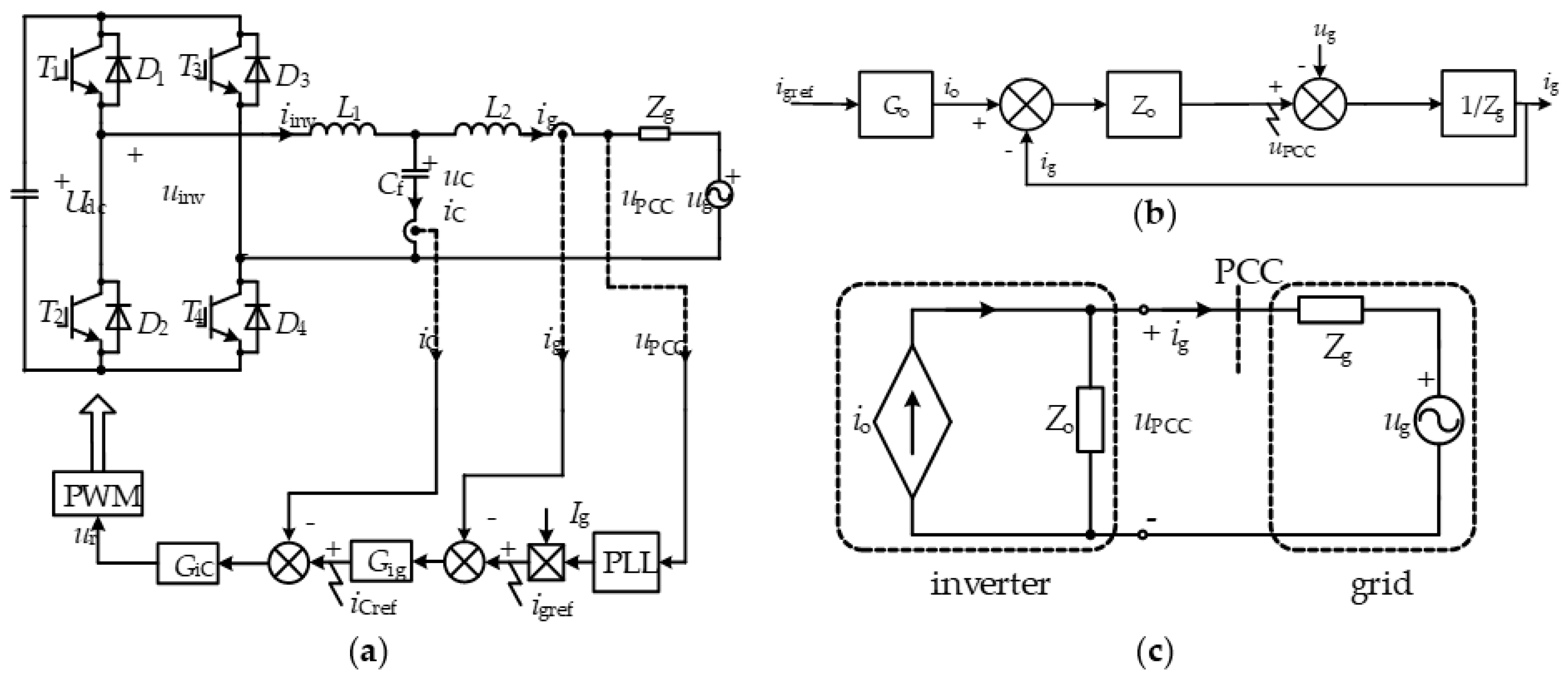
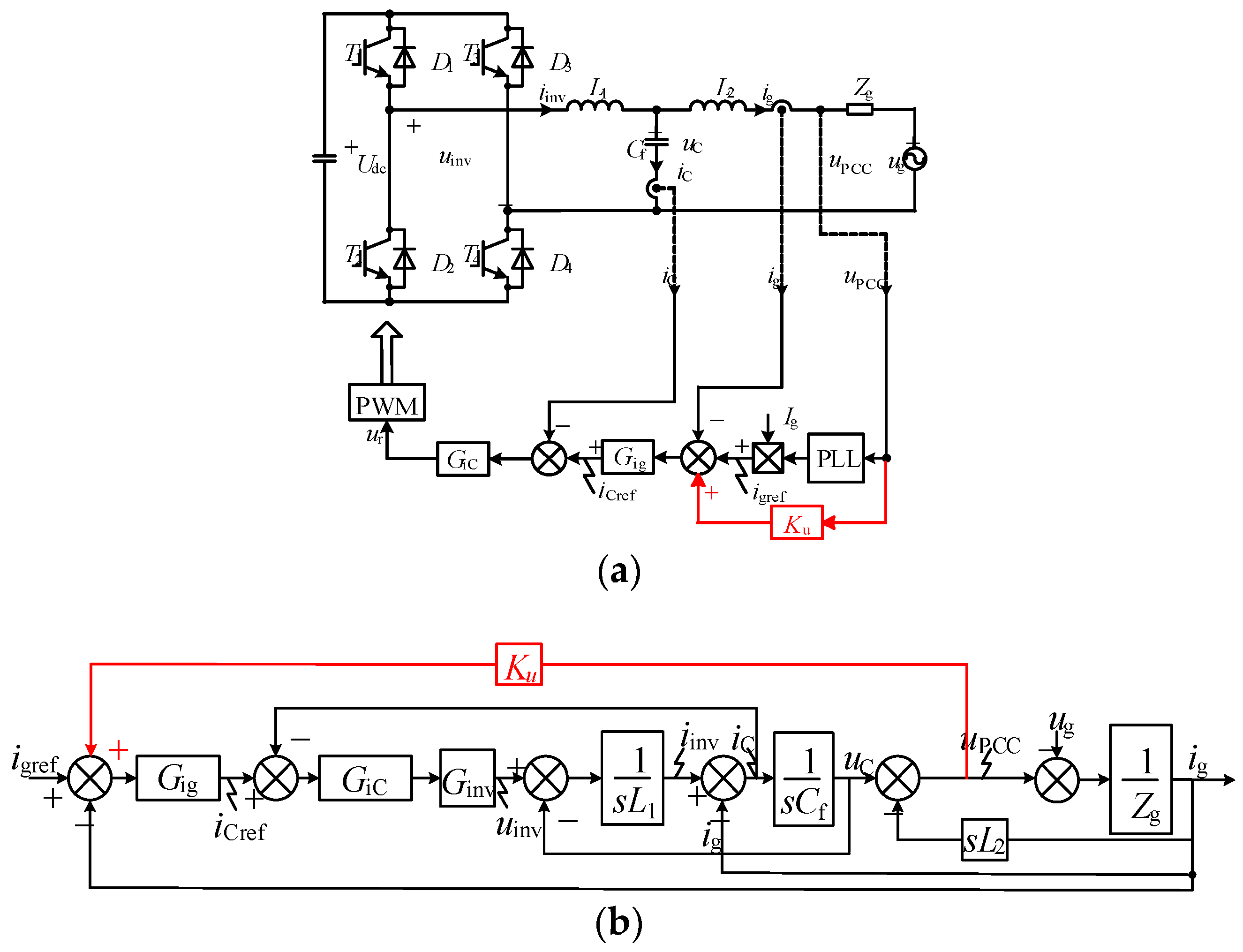
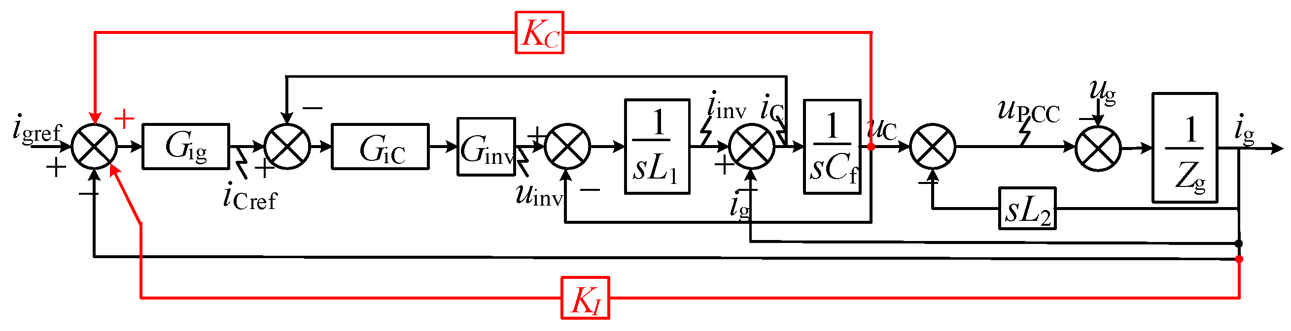
The LCL-type grid-tied inverter with dual loop of capacitor current and grid current is employed. The structure is shown in Figure 1a, where Udc, uinv, uC, uPCC, and ug, represent DC voltage, voltage at inverter side, capacitor voltage, voltage at point of common coupling, and grid voltage, respectively. iinv, iC, ig, iref, Ig, and iCref represent current at inverter side, capacitor current, grid current, reference current, the magnitude of the reference current, and the reference capacitor current, respectively. L1, L2, Cf, and Zg represent the filter inductor at the inverter side, filter inductor at grid side, filter capacitor, and grid impedance, respectively. Gig and Gic represent the grid current regulator and the capacitor current regulator, respectively.
iref and io are satisfied with io = igrefGo, where Go is a transfer function of current gain. Figure 1c shows the equivalent circuit model. It consists of a controlled current source in parallel with an output impedance and a voltage source in series with a grid impedance [6].
It is found in (1) that ig is affected by io, ug, Zo, and Zg. If Zo is increased, the second item of (1) will be decreased. Therefore, the impact of ug on ig will be reduced by enhancing Zo. If Zo is increased to be much larger than Zg, that is, Zo >> Zg, (1) will be simplified to
It can be found that the impact of grid voltage disturbance on grid current can be reduced by increasing the output impedance, thereby improving the quality of current into grid. Therefore, ig is approximately affected by io but not affected by ug and Zg.
2.2. Deduction Principle Based on Output Impedance Models
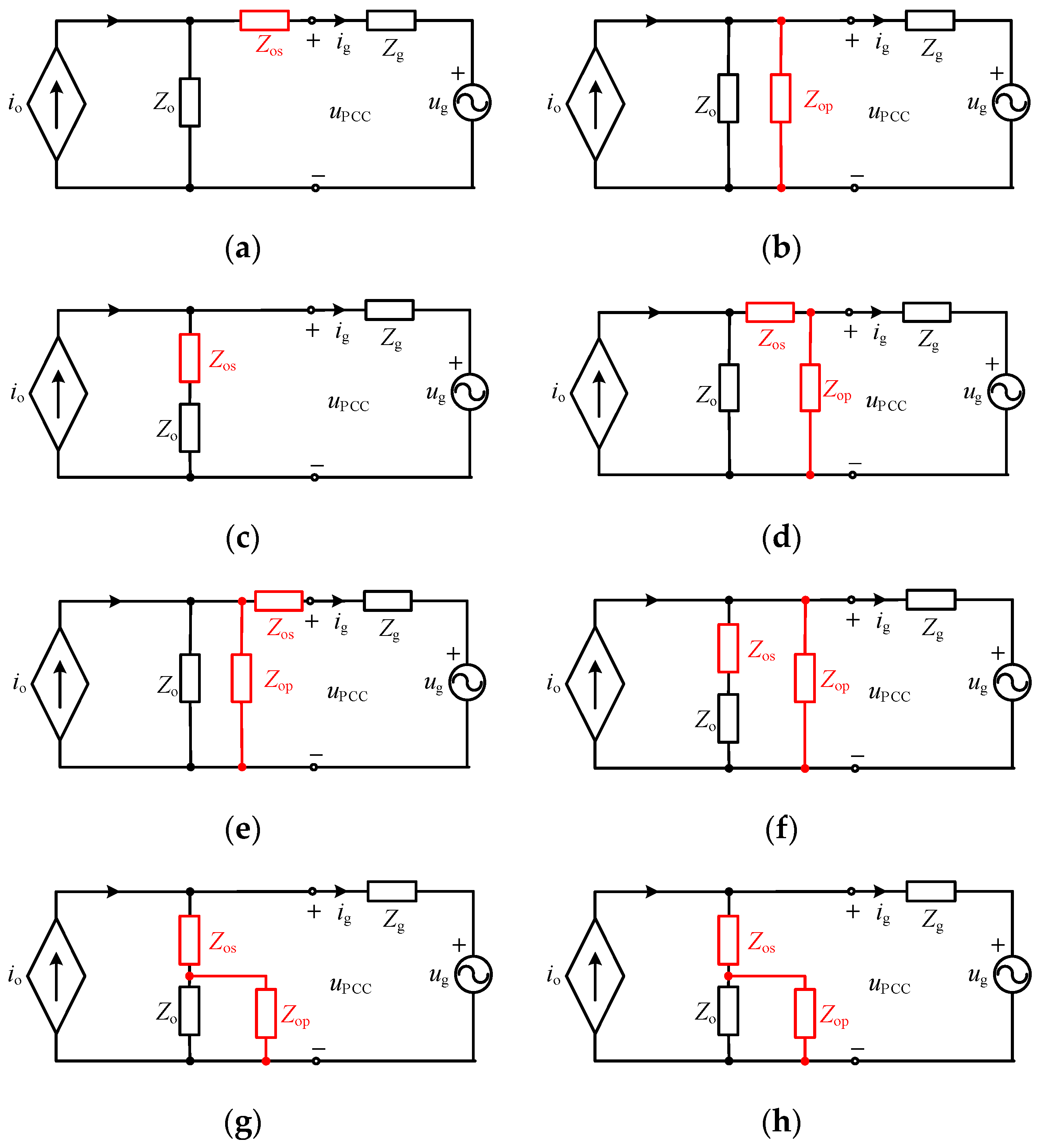
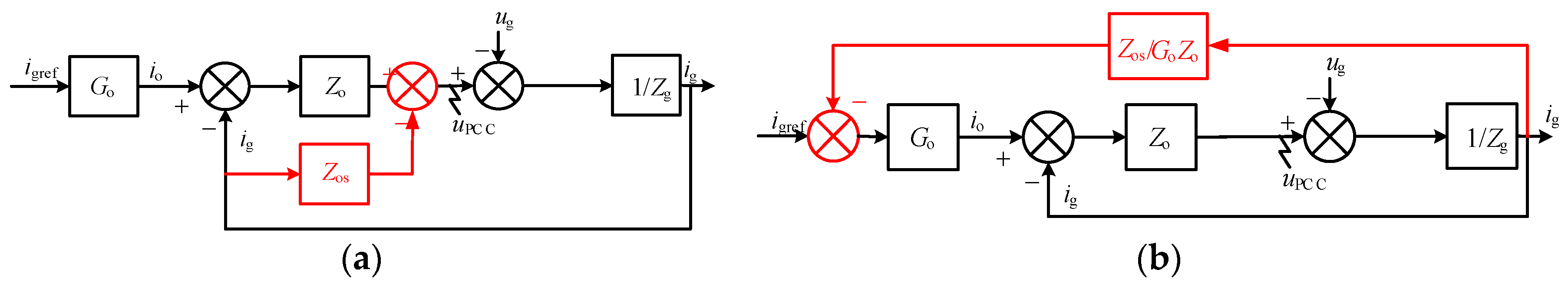
If an extra impedance Zos is added to the grid side (shown in Figure 2a), the control structure will be changed into Figure 3a. Compared to Figure 1b, a grid current feedback loop is added to the control loop. To conveniently make a further control, the reference current iref is chosen, since a single point that has physical meaning is needed. Then, Figure 3a can be transferred to Figure 3b. It is obvious that the two structures are an equivalent formation. Similarly, the other reshaping ways shown in Figure 2b–h can be transferred to Figure 4b–h, respectively.
Figure 4b,c,f,g, are grid voltage feedback control loops which feed grid voltage back to the reference current point. Figure 4a is a grid current feedback control loop which feeds the grid current back to the reference current, and Figure 4d,e,h are the combinations of grid voltage and grid current feedback control loops.
From Figure 4a–h, two basic methods are obtained which can be employed to reshape output impedance: (a) grid voltage feedback control strategy and (b) grid current feedback control strategy. In the next section, the impact of output impedance based on two basic methods will be analyzed.
3. Analysis of Impact on Output Impedance of Various Control
3.1. Impact on Output Impedance Using Voltage Feedback Control
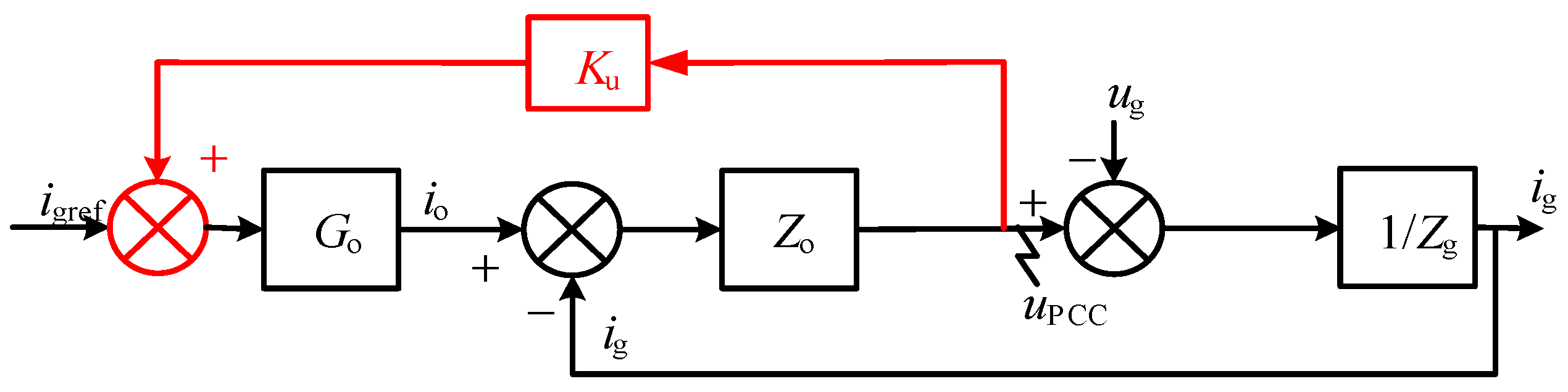
For convenience, Ku is adopted to uniformly represent the feedback coefficient when the grid voltage feedback control is employed. Ku can be expressed either as a constant value or a transfer function. Its control diagram is shown in Figure 5.
The new output impedance Zou is
Considering G0 is positive in general within the control bandwidth, Zou can be enhanced when Ku is positive.
3.2. Impact on Output Impedance Using Current Feedback Control
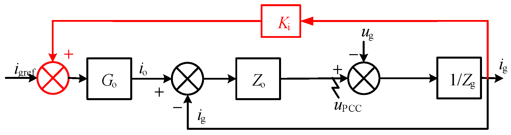
Ki represents the feedback coefficient when the grid current feedback control is employed. The control diagram is shown in Figure 6.
The new output impedance Zoi is
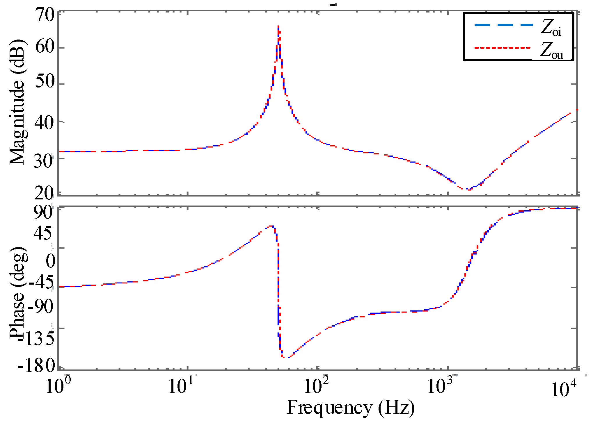
As indicated in (4), Zoi will be enhanced when Ki is negative. If (5) is satisfied, the two basic methods will have an identical ability to enhance output impedance. Bode plots are given in Figure 7 to verify the enhancement effectiveness of the output impedance.
- (a).
- As indicated in (4), Zoi will be enhanced when Ki is negative. If (5) is satisfied, the two basic methods will have an identical ability to enhance output impedance. Bode plots are given in Figure 7 to verify the enhancement effectiveness of the output impedance. The output impedance will be enhanced when Ku is positive for voltage feedback control, while Ki is negative for current feedback control.
- (b).
- The capacity of the two basic methods to reshape the output impedance is identical and they are equivalent when (5) is satisfied except in one circumstance, that is, when Ku is equal to 1/GoZo, Ki will trend to be infinite.
To obtain the largest gain of output impedance in order to prove that the basic impedance reshaped methods have the instructive significance for the enhancement of output impedance, a specific example is illustrated.
3.3. Impedance Enhancement Control Loop Based on Basic Impedance Reshaped Methods
Take the dual loop with capacitor current and grid current feedback as an example. When a grid voltage feedback control loop is added to the reference current, as shown in Figure 8a, the control diagram can be obtained (Figure 8b).
According to Figure 8b, the original output impedance without grid voltage feedback control loop is
Go can be calculated as
The reshaped output impedance can be calculated according to
If the denominator of (8) is zero, the output impedance can be enhanced as much as possible. Then, Ku is
Simplify (9) and the deformed feedback coefficient K’u is
In order to reduce high-frequency noise introduced by the second-order differential item K’u, a first-order low pass filter is employed. The output impedance will turn into
where TLPF is the time constant of the low-pass filter. The voltage harmonics are mainly considered about less than 40th, and the cut-off frequency of the low-pass filter should be larger than 2 kHz in order to enhance output impedance as much as possible. So, TLPF = 40 μs. (Cut-off frequency is 3980 Hz, approximately).
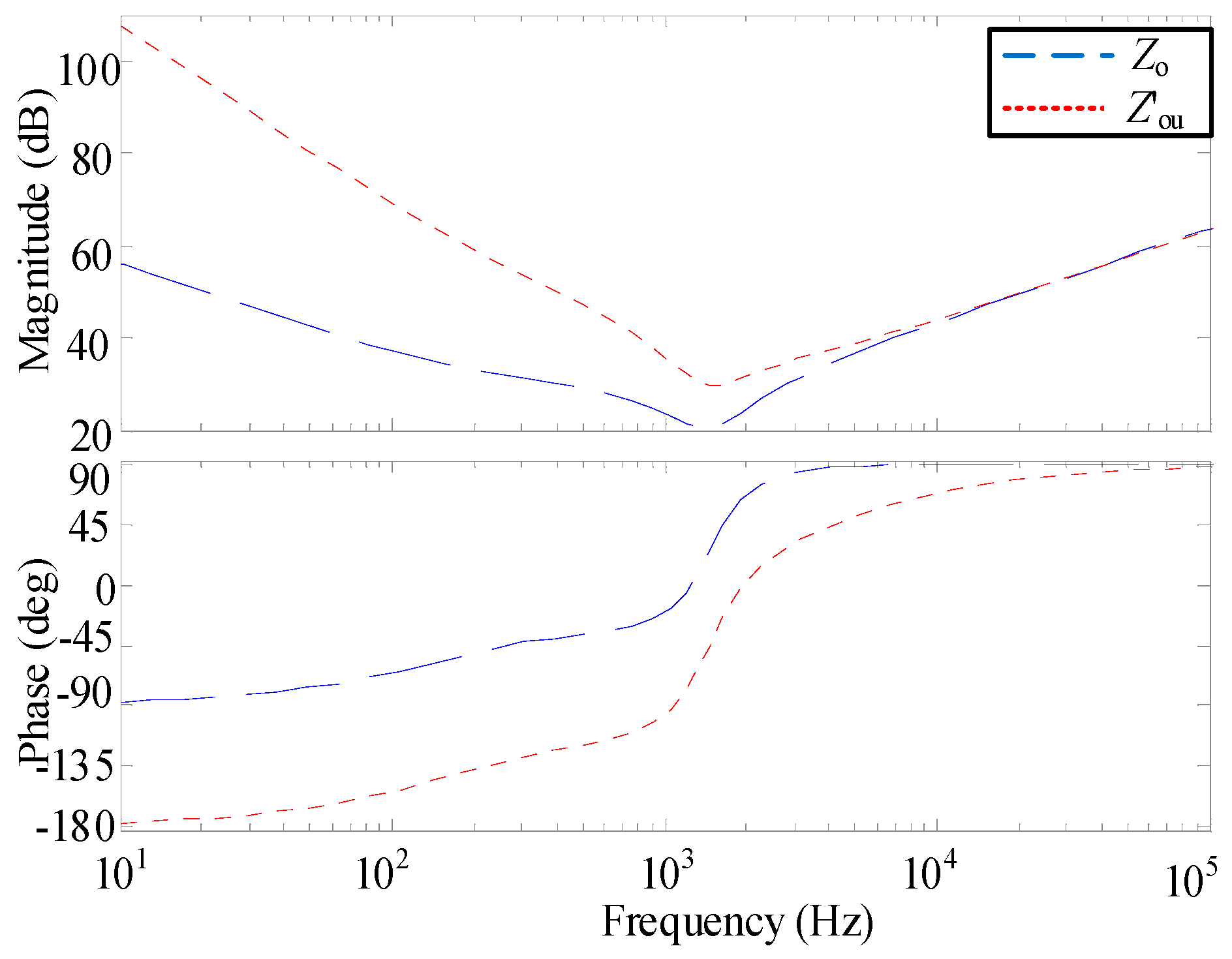
The parameters of an LCL inverter system are given in Table 1. According to (8), (11), and Table 2, the original output impedance and reshaped output impedance can be obtained, as shown in Figure 9. Figure 9 shows that the reshaped output impedance is obviously enhanced under the cut-off frequency, and the highest gain is about 1000 times greater than before.
Actually, this method is also called the full feedforward control strategy [9]. The principle of reshaped output impedance is elaborately described in previous sections. Based on the impedance model, two basic methods of reshaping output impedance are obtained, and a specific example is illustrated to prove the effectiveness of the basic methods. Further, it is necessary to apply the methods to engineering implementation.
4. Implementation and Optimization of Control-Loop-Based Impedance Enhancement
According to the Kirchhoff voltage law, grid voltage is equal to the difference between capacitor voltage and grid-side inductor voltage, and the expression of the feedback branch can be transformed to
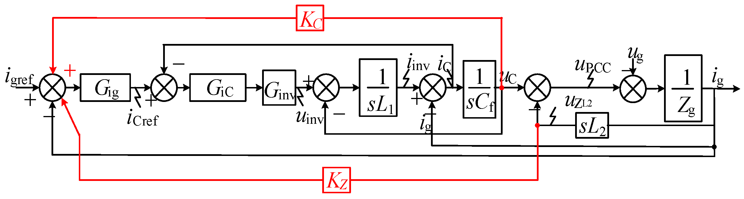
The expression of the feedback branch turns from uPCCKu to (uC − uL2) Ku, which means the control loop turns from a single loop of grid voltage to a dual loop of capacitor voltage and inductor voltage. If the feedback coefficient is equal to Ku, the capacity of reshaping output impedance is identical to the grid voltage feedforward control. The control structure is shown in Figure 10. KZ is the feedback coefficient of the grid-side inductor voltage. A new control loop structure is created through a split. Similarly, the inductor voltage at grid side is also equal to the grid current multiplied by the inductor impedance, and then the grid voltage also can be transformed to
where ZL2 represents inductor impedance. The control structure is shown in Figure 11. KI is the feedback coefficient of the grid current.
To obtain a simpler control loop, continue to simplify to
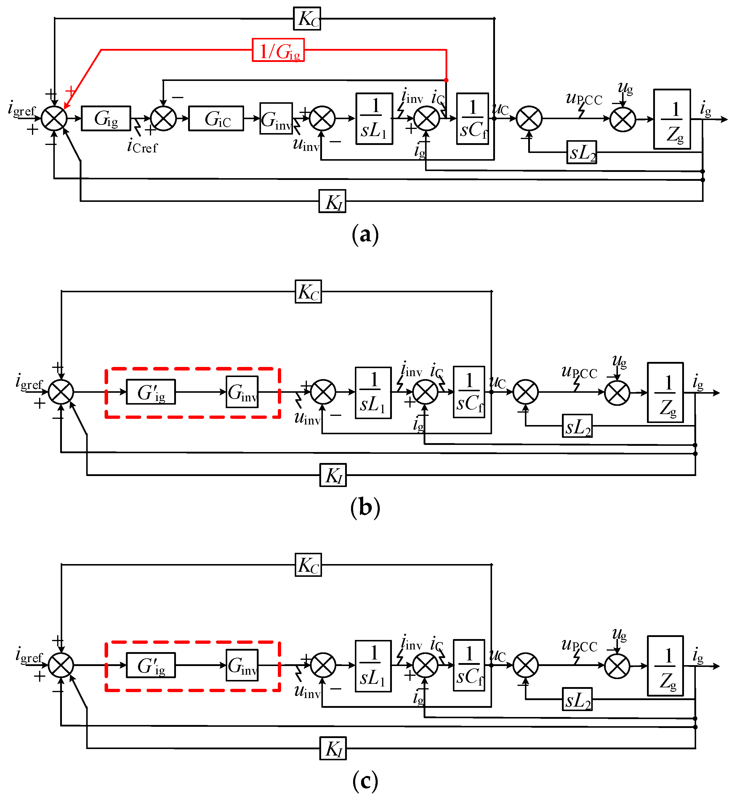
Compared to the FF control strategy, the capacitor voltage, capacitor current, and grid current feedback control loops are employed instead of the grid voltage feedback control loop as shown in Figure 12a. The control structure in Figure 12a can be optimized to Figure 12b through simplifying the control loops where the new controller G’ig equals GigGiC. G’ig is a proportional-resonant controller similar to Gig in the FF control strategy. Otherwise, the proposed control method is derived from the FF control strategy, and the capability of enhancing output impedance regarding the two methods is identical, as is the control bandwidth. The specific control structure of the proposed method is shown in Figure 12c. It shows that the inner capacitor current loop is eliminated and the capacitor current is no longer needed compared to the FF control strategy. Therefore, the cost will be reduced and the implementation in practice will be convenient.
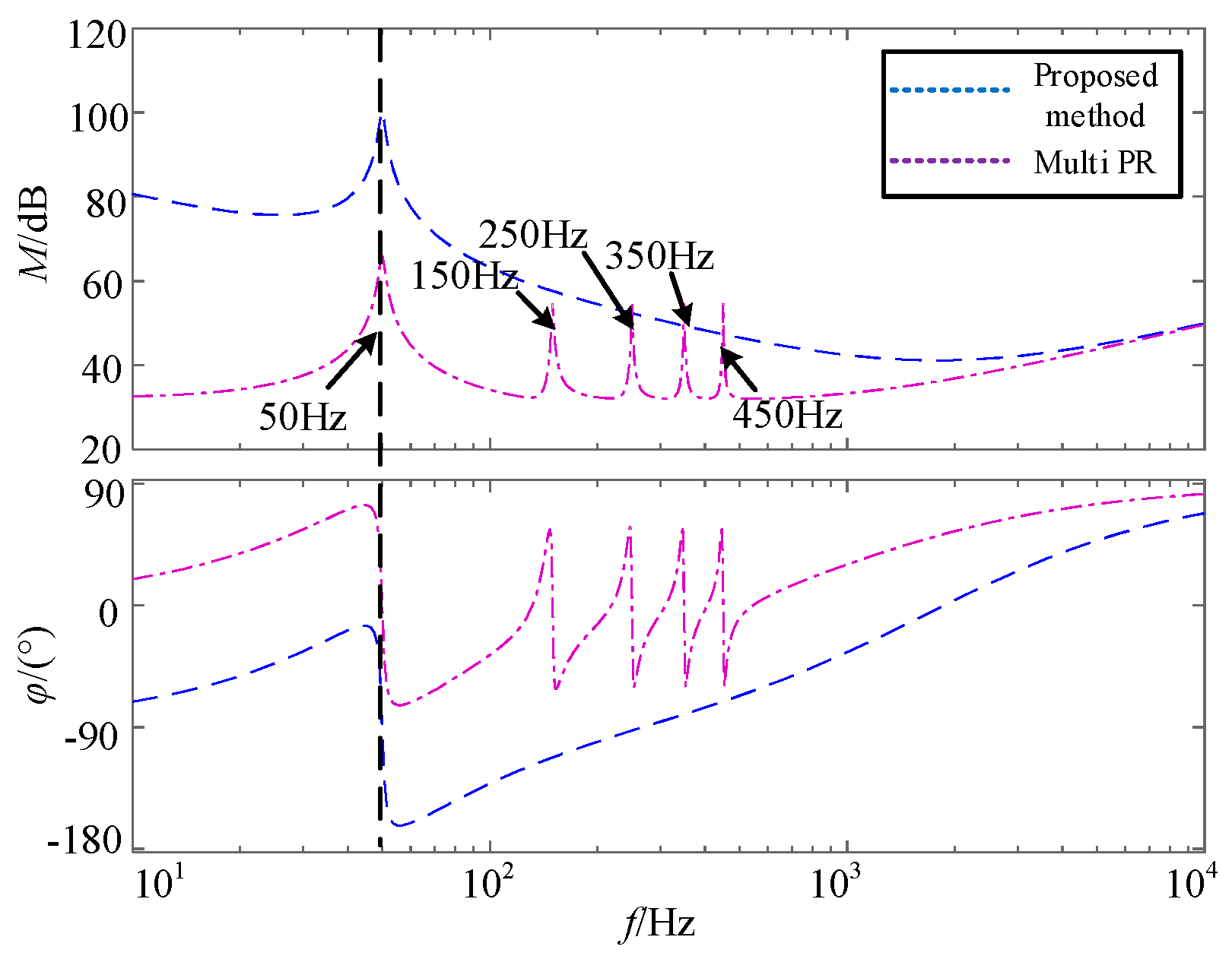
To deal with harmonic influences of the grid voltage on the grid current, the capacitor feedforward control loop is proposed from the perspective of enhancing output impedance. The output impedance is enhanced in the full bandwidth compared to the multiple PR (Proportional Resonance) controller which enhances the output impedance only at the selected frequency, as shown in Figure 13. As mentioned in [18], the repetitive control is equivalent to a combination of a proportional controller and multiple parallel resonant controller. The effectiveness of enhancing output impedance is similar to the multiple PR controller. Meanwhile, the repetitive control is a relative complex for implementation. Therefore, the proposed control strategy with the capacitor feedforward control loop is convenient to enhance the output impedance.
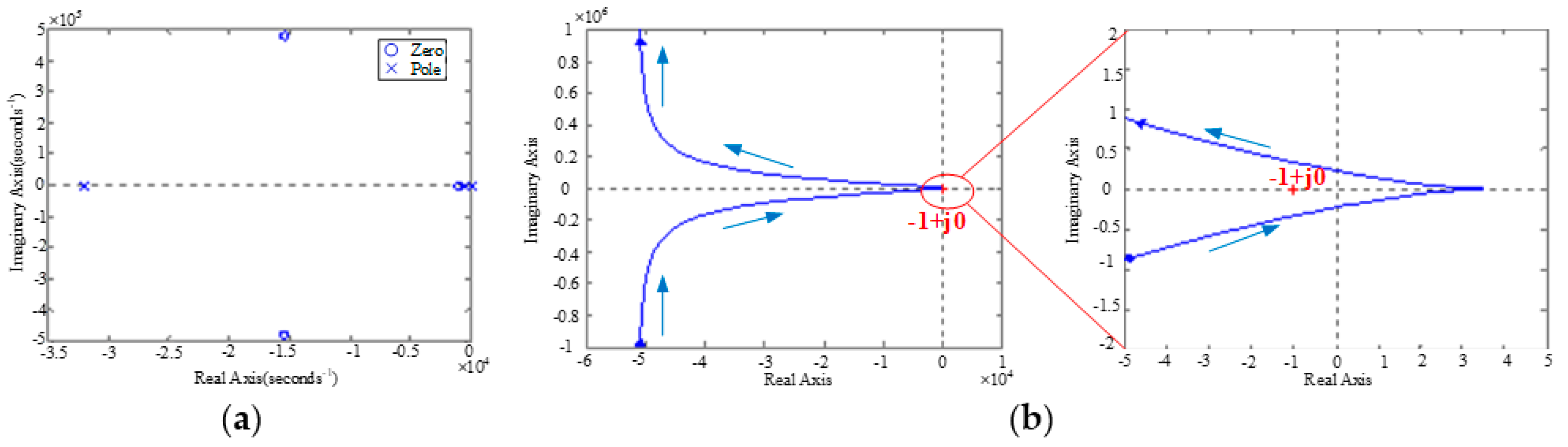
The stability of the proposed control strategy can be determined by the ratio of the grid impedance and output impedance, that is, Zg/Z’ou should be satisfied with the Nyquist criterion [18]. Here, the grid impedance is 0.2 Ω/0.08 mH, and Z’ou is shown in (11).
It can be found that in Figure 14, there is no pole at the right side of the s plane, and its Nyquist curve does not circle the point −1 + j0. According to the Nyquist criterion, this system is stable.
5. Simulations and Experimental Verifications
To verify the proposed control strategy, a single-phase grid-tied inverter with an LCL filter was established in PSIM (Power Simulation), and the parameters are shown in Table 1. The 3rd, 5th, 7th, 9th, 11th, and 13th harmonics were injected into grid voltage, and the magnitude of each harmonic was 5%, 6%, 1%, 1.5%, 3.5%, and 3%, respectively.
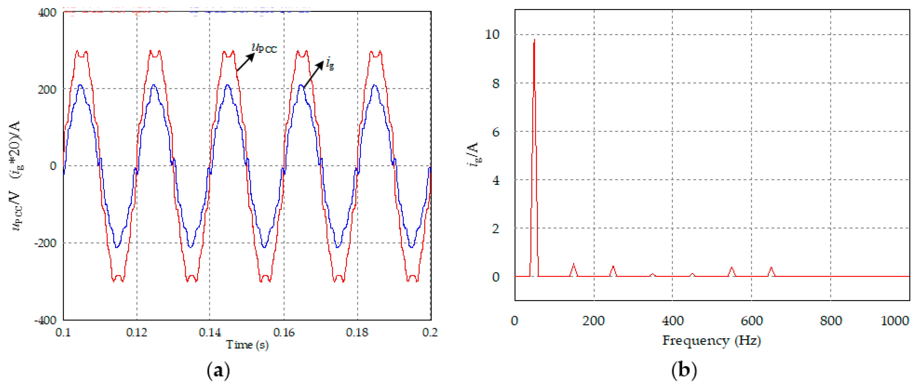
In order to be more realistic, a 0.5 Ω resistor was concatenated on the DC side to simulate the true DC voltage source in this paper. Figure 15a shows the simulation results of a dual-loop control strategy with capacitor current and grid current. It can be seen that both the voltage and current are heavily distorted. The THD (total harmonic distorted) of the grid current was 7.4%, as shown in Figure 15b. (ig*20)/A in Figure 15a, Figure 16a and Figure 17a indicates that the grid current is 20 times greater than the original value.
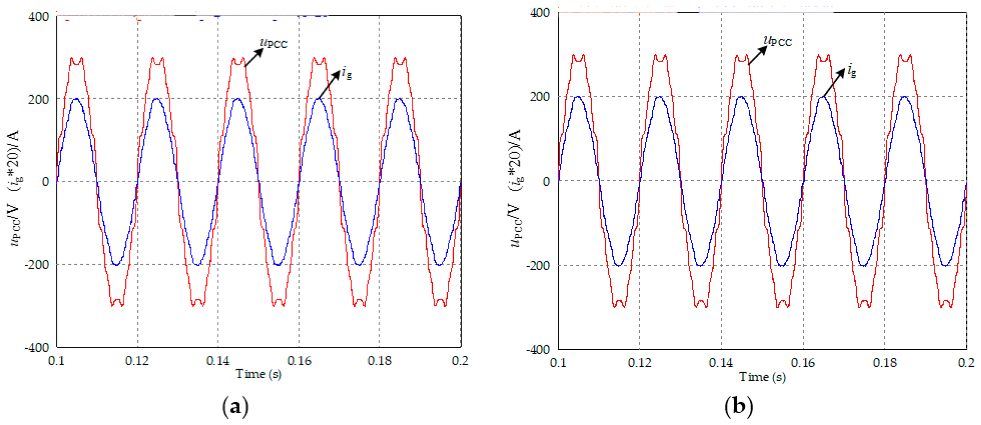
By introducing the grid voltage feedforward control loop, the impact of distorted grid voltage on the grid current is smaller. The current wave in Figure 16a is approximately sinusoidal and the THD of the grid current reduces to 3.3% in Figure 16b. It is suggested that by enhancing the output impedance, the current harmonics are suppressed, and the grid voltage feedforward control strategy is effective at suppressing the grid voltage disturbance.
The simulation results in Figure 17a indicate that the proposed control strategy employing the capacitor voltage and grid current is also effective at suppressing current harmonics. It is suggested that the proposed control strategy also has an identical ability of enhancing output impedance with the grid voltage feedforward control strategy. The THD of the grid current is 2.8% in Figure 17b and it achieves the requirements of grid connectedness.
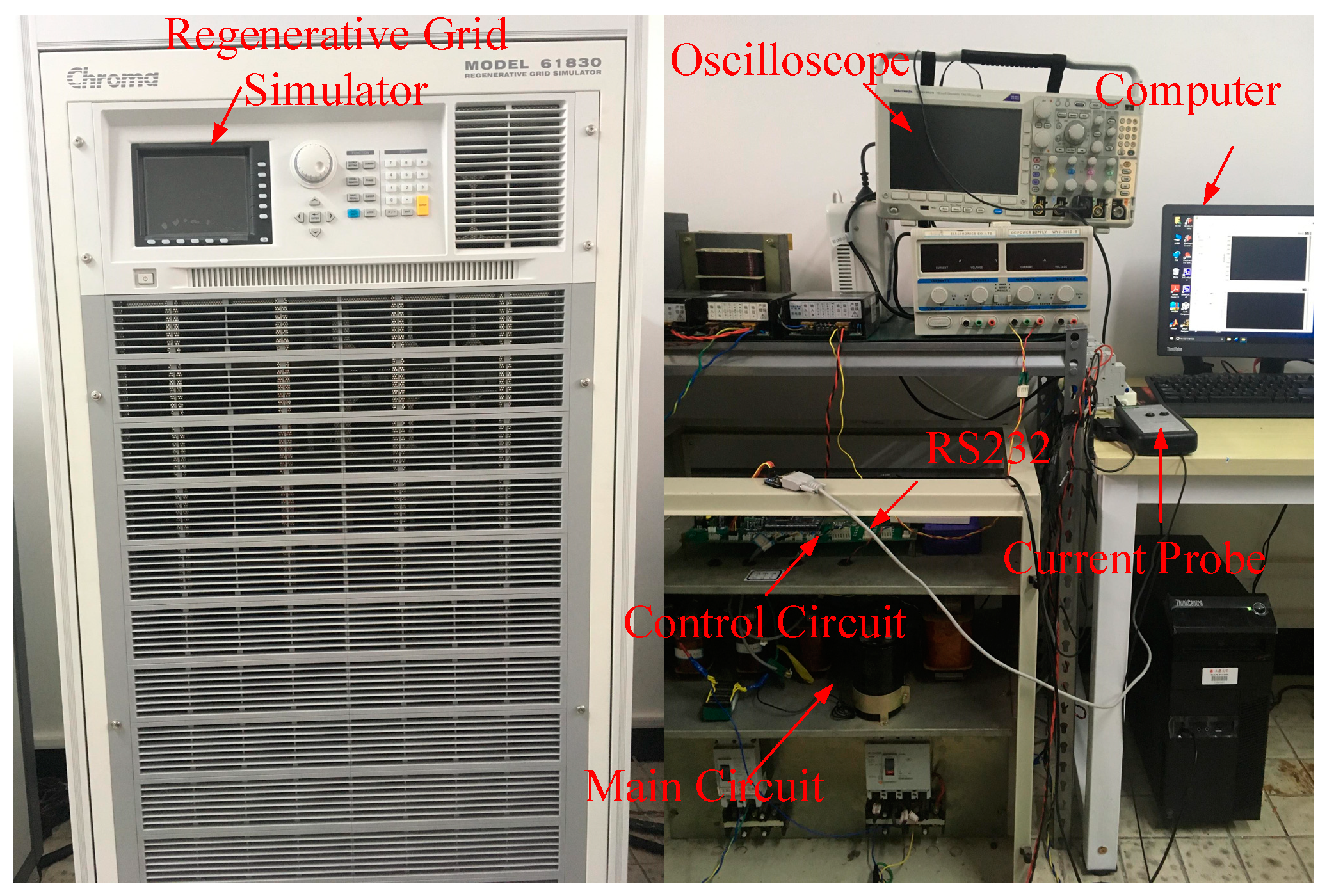
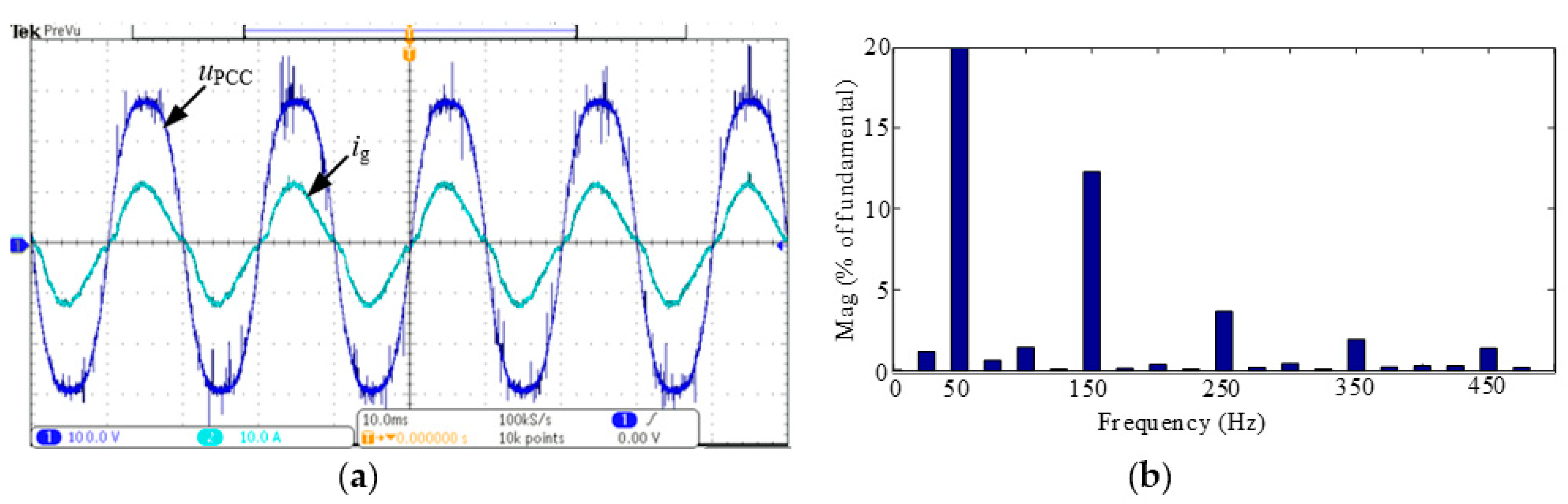
In order to further verify the proposed control strategy, a prototype was designed and established in the laboratory, as shown in Figure 18. The parameters were identical to the simulation as shown in Table 2. The experimental results of the dual-loop control strategy with the capacitor current and grid current feedback, the grid voltage feedforward control, the proposed control strategy of capacitor voltage, and the grid current are shown in Figure 19, Figure 20 and Figure 21 respectively.
The current harmonics are well suppressed when the grid voltage feedforward control is employed, as shown in Figure 19 and Figure 20. The proposed control strategy achieves the same ability of suppressing current harmonics with the FF as shown in Figure 21. The THDs of the grid current with different harmonic suppression schemes are shown in Table 2.
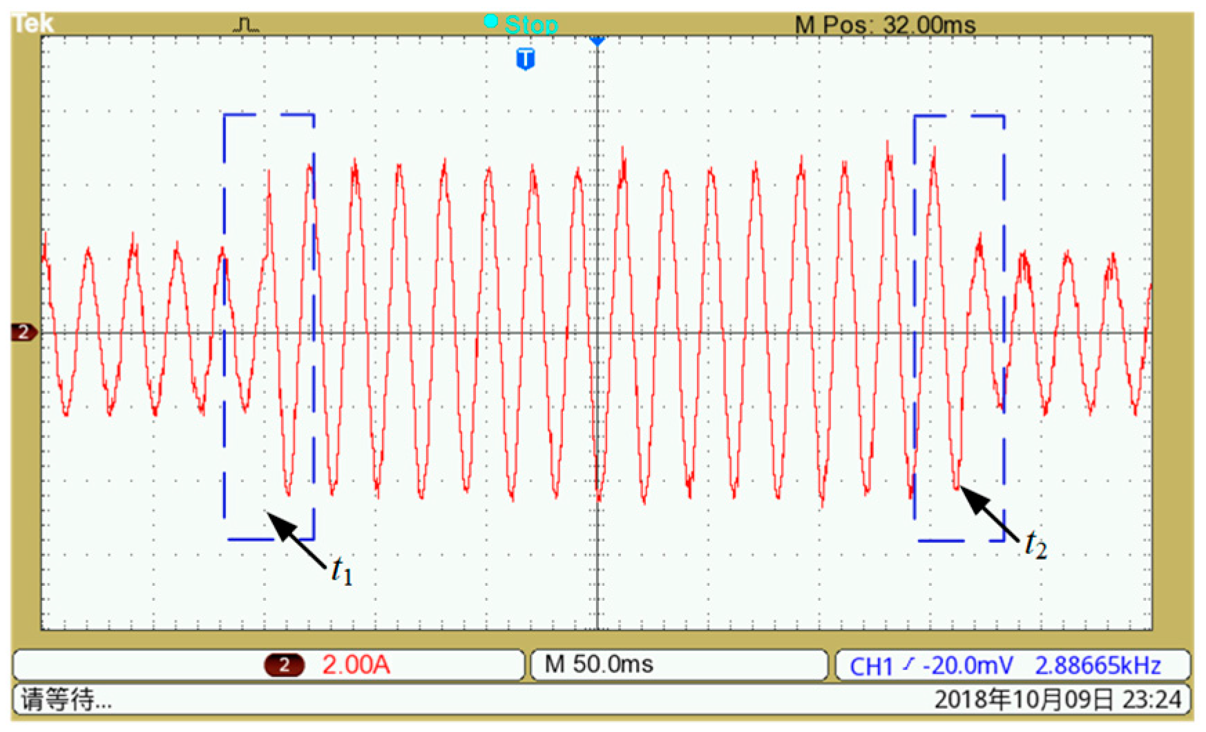
To show the good transient performances, dynamic experiments were carried out in which the reference current was given from 2 to 4 A at t1 and from 4 to 2 A at t2, respectively. The experimental results are shown in Figure 22 and indicate that dynamic performance can be guaranteed when the proposed control method is adopted.
6. Conclusions
The principle and implementation of control-loop-based impedance enhancement of grid-tied inverters for harmonic suppression was proposed in this paper in detail. Based on the idea of reshaping output impedance, two basic methods of impedance reshaping were obtained. It was found that the grid voltage feedback control has an infinite impedance enhancement ability which can eliminate the influences of the distorted grid voltage in theory. A specific example was illustrated to prove the effectiveness of the basic methods of reshaping impedance. Based on the idea of infinite impedance reshaping, the implementation of control loops was made step by step. To find an optimized control loop, a novel control loop that can eliminate the inner capacitor current loop and reduce the number of sensors was proposed through splitting the grid voltage. Finally, the simulation and experimental results were illustrated to verify the effectiveness of the proposed control strategy.
Author Contributions
F.W. and L.Z. provided the original idea of this paper and organized the manuscript. H.G. and X.F. attended the discussions when the simulations and experiments were carried out. All the authors gave the comments and suggestions on the writing and descriptions on the manuscript.
Funding
This work is supported by National Key R&D Program of China (2017YFE0112400) and National Natural Science Foundation of China (51577113).
Conflicts of Interest
The authors declare no conflict of interest.
References
- Blaabjerg, F.; Teodorescu, T.; Liserre, M.; Timbus, A.V. Overview of control and grid synchronization for distributed power generation systems. IEEE Trans. Ind. Electron. 2006, 51, 1398–1409. [Google Scholar] [CrossRef]
- IEEE Standards Coordinating Committee. IEEE Standard for Interconnecting Distributed Resources with Electric Power Systems; IEEE Std 1547-2003; IEEE: Piscataway, NJ, USA, 2018. [Google Scholar]
- Xin, Z.; Loh, P.C.; Wang, X.; Blaabjerg, F.; Tang, Y. Highly accurate derivatives for LCL-filtered grid converter with capacitor voltage active damping. IEEE Trans. Power Electron. 2016, 31, 3612–3625. [Google Scholar] [CrossRef]
- Tang, Y.; Loh, P.C.; Wang, P.; Choo, F.H.; Gao, F. Exploring inherent damping characteristic of LCL-filters for three-phase grid-connected voltage source inverters. IEEE Trans. Power Electron. 2012, 27, 1433–1443. [Google Scholar] [CrossRef]
- Chenlei, B.; Xinbo, R.; Xuehua, W.; Weiwei, L.; Donghua, P.; Kailei, W. Step-by-step controller design for LCL-type grid-connected inverter with capacitor–current-feedback active-damping. IEEE Trans. Power Electron. 2014, 29, 1239–1253. [Google Scholar] [CrossRef]
- Wang, F.; Duarte, J.L.; Hendrix, M.A.M. Modeling and analysis of grid harmonic distortion impact of aggregated DG Inverters. IEEE Trans. Power Electron. 2011, 26, 786–797. [Google Scholar] [CrossRef]
- Guoqiao, S.; Xuancai, Z.; Jun, Z.; Dehong, X. A new feedback method for PR current control of LCL-filter-based grid-connected invertir. IEEE Trans. Ind. Electron. 2010, 57, 2033–2041. [Google Scholar] [CrossRef]
- Guoqiao, S.; Dehong, X.; Luping, C.; Xuancai, Z. An improved control strategy for grid-connected voltage source inverters with an LCL filter. IEEE Trans. Power Electron. 2008, 23, 1899–1906. [Google Scholar] [CrossRef]
- Wang, X.; Ruan, X.; Liu, S.; Tse, C.K. Full feedforward of grid voltage for grid-connected inverter with LCL filter to suppress current distortion due to grid voltage harmonics. IEEE Trans. Power Electron. 2010, 25, 3119–3127. [Google Scholar] [CrossRef]
- Li, W.; Ruan, X.; Pan, D.; Wang, X. Full-feedforward schemes of grid voltages for a three-phase LCL-type grid-connected invertir. IEEE Trans. Ind. Electron. 2013, 60, 2237–2250. [Google Scholar] [CrossRef]
- Abeyasekera, T.; Johnson, C.M.; Atkinson, D.J.; Armstrong, M. Suppression of line voltage related distortion in current controlled grid connected inverters. IEEE Trans. Power Electron. 2005, 20, 1393–1401. [Google Scholar] [CrossRef]
- Park, S.Y.; Chen, C.L.; Lai, J.S.; Moon, S.R. Admittance compensation in current loop control for a grid-tie LCL fuel cell inverter. IEEE Trans. Power Electron. 2005, 23, 1716–1723. [Google Scholar] [CrossRef]
- Yang, D.; Ruan, X.; Wu, H. Impedance shaping of the grid-connected inverter with LCL filter to improve its adaptability to the weak grid condition. IEEE Trans. Power Electron. 2014, 29, 5795–5805. [Google Scholar] [CrossRef]
- Xu, J.; Tang, T.; Xie, S. Evaluations of current control in weak grid case for grid-connected LCL-filtered invertir. IET Power Electron. 2013, 6, 227–234. [Google Scholar] [CrossRef]
- Yi, L.; Wei, X.; Chaoxu, M.; Zhengming, Z.; Hongbing, L.; Zhiyong, L. New hybrid damping strategy for grid-connected photovoltaic inverter with LCL filter. IEEE Trans. Appl. Supercond. 2014, 24. [Google Scholar] [CrossRef]
- Pappalardo, C.M.; Guida, D. Use of the Adjoint Method for Controlling the Mechanical Vibrations of Nonlinear Systems. Machines 2018, 6, 19. [Google Scholar] [CrossRef]
- Yang, Y.; Zhou, K.; Wang, H.; Blaabjerg, F.; Wang, D.; Zhang, B. Frequency adaptive selective harmonic control for grid-connected inverters. IEEE Trans. Power Electron. 2015, 30, 3912–3924. [Google Scholar] [CrossRef]
- Sun, J. Impedance-based stability criterion for grid-connected inverters. IEEE Trans. Power Electron. 2011, 26, 3075–3078. [Google Scholar] [CrossRef]
Figure 1.
LCL (Inductor-Capacitor-Inductor)-type grid-tied inverter for single phase: (a) structure of main circuit; (b) structure of impedance model; (c) structure of equivalent circuit model.
Figure 1.
LCL (Inductor-Capacitor-Inductor)-type grid-tied inverter for single phase: (a) structure of main circuit; (b) structure of impedance model; (c) structure of equivalent circuit model.

Figure 2.
Methods of reshaping output impedance based on equivalent circuit: (a,c) series reshaping; (b) parallel reshaping; (d–h) combination of series and parallel reshaping.
Figure 2.
Methods of reshaping output impedance based on equivalent circuit: (a,c) series reshaping; (b) parallel reshaping; (d–h) combination of series and parallel reshaping.

Figure 3.
Block diagram of reshaping output impedance: (a) impedance model; (b) deformed impedance model.
Figure 3.
Block diagram of reshaping output impedance: (a) impedance model; (b) deformed impedance model.

Figure 4.
Methods of reshaping output impedance based on control loops: (a,c) series reshaping; (b) parallel reshaping; (d–h) combination of series and parallel reshaping.
Figure 4.
Methods of reshaping output impedance based on control loops: (a,c) series reshaping; (b) parallel reshaping; (d–h) combination of series and parallel reshaping.
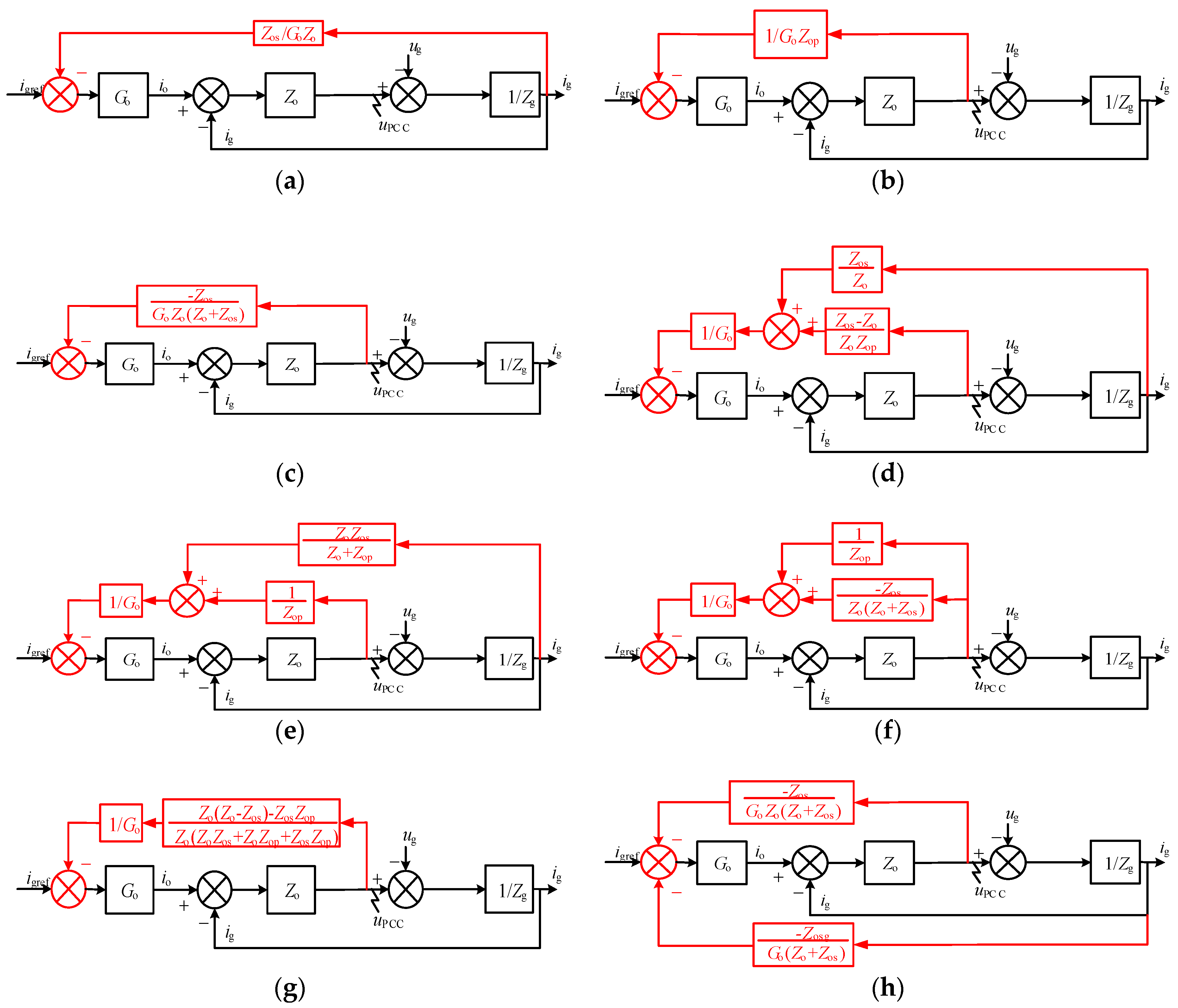
Figure 5.
The structure of grid voltage feedback control.

Figure 6.
The structure of grid current feedback control.

Figure 7.
Bode plots of output impedance with two basic impedance reshaped methods.

Figure 8.
LCL-type grid-tied inverter for single-phase: (a) the main circuit structure with grid voltage feedback control loop; (b) control loop.
Figure 8.
LCL-type grid-tied inverter for single-phase: (a) the main circuit structure with grid voltage feedback control loop; (b) control loop.

Figure 9.
Bode plot of output impedance based on voltage feedback control.

Figure 10.
The structure of capacitor voltage and grid-side inductor voltage feedback control loop.

Figure 11.
The structure of capacitor voltage and grid current feedback control loop.

Figure 12.
Proposed control loop of capacitor voltage and grid current feedback. (a) Optimization step I; (b) optimization step II; (c) proposed control structure, respectively.
Figure 12.
Proposed control loop of capacitor voltage and grid current feedback. (a) Optimization step I; (b) optimization step II; (c) proposed control structure, respectively.

Figure 13.
Comparison of the output impedance with the proposed method and multiple PR (Proportional Resonance) controller.
Figure 13.
Comparison of the output impedance with the proposed method and multiple PR (Proportional Resonance) controller.

Figure 14.
Pole-zero plot and Nyquist curve of Zg/Z’ou. (a) Pole-zero plot; (b) Nyquist curve, respectively.
Figure 14.
Pole-zero plot and Nyquist curve of Zg/Z’ou. (a) Pole-zero plot; (b) Nyquist curve, respectively.

Figure 15.
Simulation results of dual-loop control strategy. (a) Waveforms of grid voltage and current. (b) FFT (Fast Fourier Transformation) analysis of grid current (THD = 7.4%).
Figure 15.
Simulation results of dual-loop control strategy. (a) Waveforms of grid voltage and current. (b) FFT (Fast Fourier Transformation) analysis of grid current (THD = 7.4%).

Figure 16.
Simulation results of grid voltage feedforward control strategy. (a) Waveforms of grid voltage and current. (b) FFT analysis of grid current (THD = 3.3%).
Figure 16.
Simulation results of grid voltage feedforward control strategy. (a) Waveforms of grid voltage and current. (b) FFT analysis of grid current (THD = 3.3%).
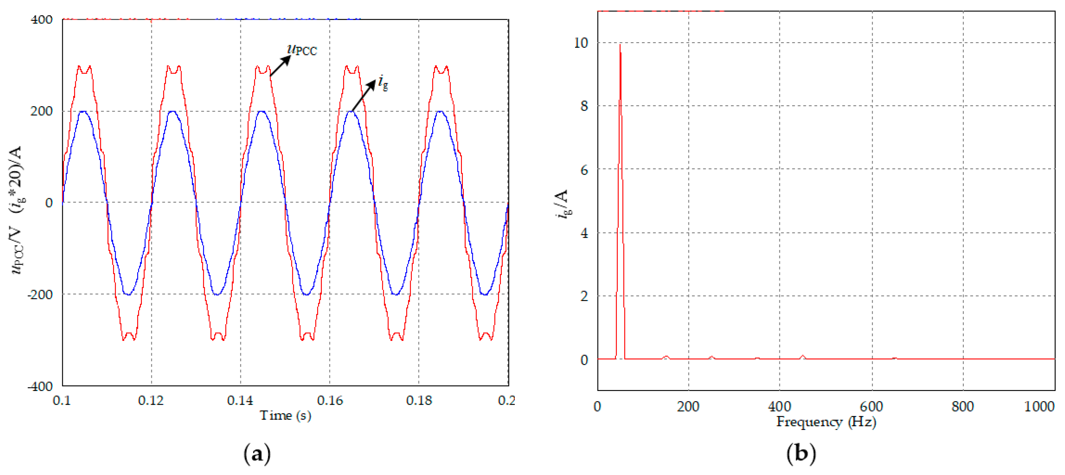
Figure 17.
Simulation results of the proposed control strategy. (a) Waveforms of grid voltage and current. (b) FFT analysis of grid current (THD = 2.8%).
Figure 17.
Simulation results of the proposed control strategy. (a) Waveforms of grid voltage and current. (b) FFT analysis of grid current (THD = 2.8%).

Figure 18.
Platform of the grid-tied inverter for single phase.

Figure 19.
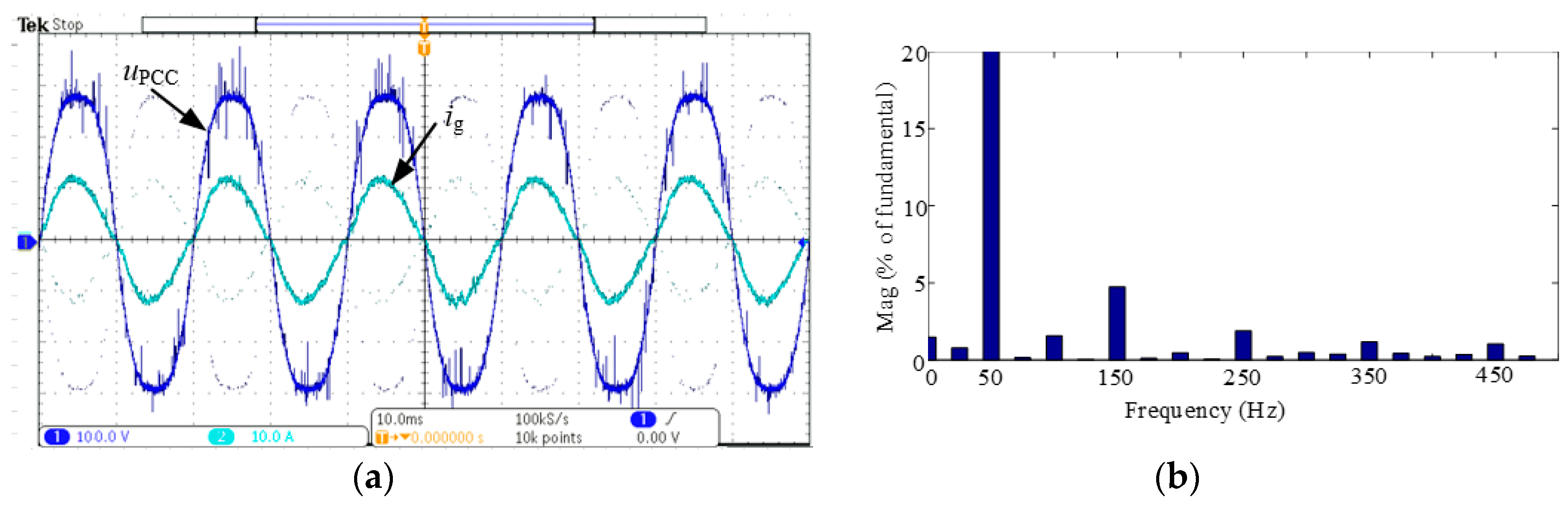
The experimental results of conventional dual-loop control strategy. (a) Waveforms of grid voltage and current. (b) The FFT analysis of grid current (THD = 13.17%).
Figure 19.
The experimental results of conventional dual-loop control strategy. (a) Waveforms of grid voltage and current. (b) The FFT analysis of grid current (THD = 13.17%).

Figure 20.
The experimental results of the FF (Feed Forward) strategy. (a) Waveforms of grid voltage and current, and (b) the FFT analysis of grid current (THD = 5.78%).
Figure 20.
The experimental results of the FF (Feed Forward) strategy. (a) Waveforms of grid voltage and current, and (b) the FFT analysis of grid current (THD = 5.78%).

Figure 21.
The experimental results of the proposed control strategy. (a) Waveforms of grid voltage and current, and (b) the FFT analysis of grid current (THD = 5.75%).
Figure 21.
The experimental results of the proposed control strategy. (a) Waveforms of grid voltage and current, and (b) the FFT analysis of grid current (THD = 5.75%).
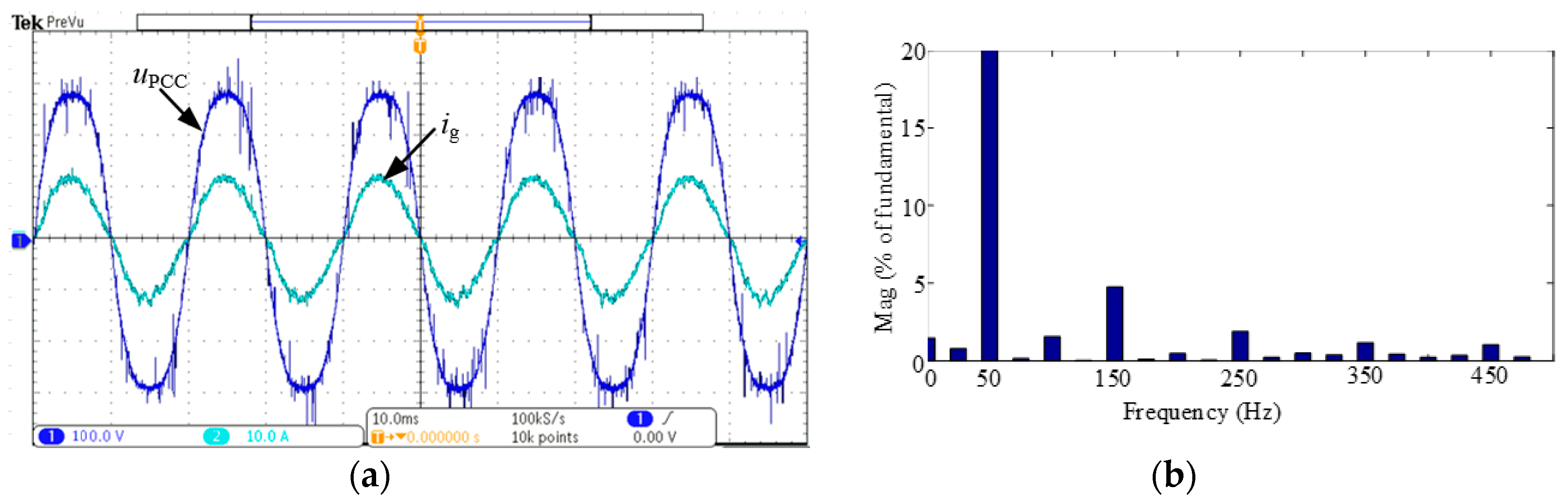
Figure 22.
Dynamic performances when the proposed control strategy is employed.


Table 1.
Parameters of single phase inverters with LCL filter.
| Symbol | Quantity | Value |
|---|---|---|
| ug | Grid voltage | 220 V |
| fg | Frequency | 50 Hz |
| Udc | DC voltage | 400 V |
| L1 | Filter inductor at inverter side | 2.4 mH |
| L2 | Filter inductor at grid side | 2.4 mH |
| Zg | Grid impedance | 0.2 Ω/0.08 mH |
| Cf | Filter capacitor | 4 μF |
| fs | Switch frequency | 16 kHz |
| Gic | Capacitor current regulator | 30 |
| Ginv | Gain of the inverter | 1 |
| Kp | Proportional coefficient | 1 |
| KR | Resonance regulator coefficient | 50 |
| ωc | Band frequency | 10 rad s−1 |
| TLPF | Time constant of low pass filter | 40 μs |
| iref | Reference current | 10 A |
Table 2.
THD of grid current under different harmonic suppression schemes.
| Control Strategy | THD of Grid Current/% |
|---|---|
| Dual-loop control strategy | 13.17 |
| Grid voltage feedforward control strategy | 5.78 |
| Proposed control strategy | 5.75 |
© 2018 by the authors. Licensee MDPI, Basel, Switzerland. This article is an open access article distributed under the terms and conditions of the Creative Commons Attribution (CC BY) license (http://creativecommons.org/licenses/by/4.0/).
Share and Cite
MDPI and ACS Style
Wang, F.; Zhang, L.; Guo, H.; Feng, X. Control-Loop-Based Impedance Enhancement of Grid-Tied Inverters for Harmonic Suppression: Principle and Implementation. Energies 2018, 11, 2874. https://doi.org/10.3390/en11112874
AMA Style
Wang F, Zhang L, Guo H, Feng X. Control-Loop-Based Impedance Enhancement of Grid-Tied Inverters for Harmonic Suppression: Principle and Implementation. Energies. 2018; 11(11):2874. https://doi.org/10.3390/en11112874
Chicago/Turabian StyleWang, Fei, Lijun Zhang, Hui Guo, and Xiayun Feng. 2018. "Control-Loop-Based Impedance Enhancement of Grid-Tied Inverters for Harmonic Suppression: Principle and Implementation" Energies 11, no. 11: 2874. https://doi.org/10.3390/en11112874
Note that from the first issue of 2016, this journal uses article numbers instead of page numbers. See further details here.