An Enhanced Control Strategy for Doubly-Fed Induction Generators Based on a Virtual Harmonic Resistor and Capacitor under Nonlinear Load Conditions

School of Electrical Engineering and Automation, Hefei University of Technology, Hefei 230009, China
*
Author to whom correspondence should be addressed.
Energies 2018, 11(10), 2613; https://doi.org/10.3390/en11102613
Submission received: 31 July 2018
/
Revised: 28 August 2018
/
Accepted: 21 September 2018
/
Published: 1 October 2018
Abstract
:Harmonic amplification for doubly-fed induction generator wind turbine systems (DFIG WTSs) will occur due to the existence of non-linear loads and reactive power compensation installation, and grid voltage and total grid current at the point of common coupling (PCC) will be distorted. An impedance model is established to analyze the interaction between DFIG WTS, non-linear loads and weak grids. Harmonic current impact factor and harmonic voltage impact factor is proposed to analyze the impact of harmonic current source on total grid current and voltage at the PCC with different control strategies. A virtual harmonic resistor and capacitor method is adopted to reduce the harmonic voltage. An impedance-based analysis method is adopted to analyze the stability of the DFIG system. To achieve optimal control of harmonic voltage and harmonic current, a coordination factor is proposed to adjust the dynamic allocation for harmonic voltage and harmonic current at PCC. The experimental results demonstrate the effectiveness of the proposed control strategy.
1. Introduction
Renewable energy technologies, especially wind power technology, have won widespread attention and seen rapid development due to the grim energy and environmental issues, and DFIG wind power systems are the most widely used [1,2,3,4,5,6]. DFIG can not only operate at variable speed constant frequency (VSVF), but also adjust a large amount of reactive power. Using a grid-side converter (GSC) and rotor-side converter (RSC) together, one can achieve the stable operation of control DFIG, and the converter only accounts for 30% of the total power-generating capacity. A GSC is used to keep dc voltage constant and adjust the power factor, so that the RSC can regulate the output stator active and reactive power independently [7,8,9,10,11]. DFIG control has been maturely researched under the ideal grid voltage conditions, but non-linear loads are often linked to the grid, which will inject harmonics into the grid, especially when parallel capacitors and line impedance are contained in weak grids, and a harmonic amplification will occur in double-fed wind power systems due to their interaction with the DFIG impedance, this leads to distortion in the total grid current and voltage at the PCC. If a conventional control strategy is adopted, distorted stator and rotor currents, fluctuating stator active and reactive power and torque are produced, which is harmful for the DFIG WTS and the grid [12,13]. There are some regulations about total harmonic distortion (THD) for grid-connected current and voltage at the PCC in grid codes [14].
Consequently, some theories have recently been developed to analyze the impact of voltage harmonics and current harmonics on the DFIG. In [15,16], an integrated mathematical model of DFIG was presented in a positive synchronous reference fame (d-q frame) under distorted grid voltage conditions, where the pulsations of electromagnetic torque and instantaneous stator active/reactive powers were fully described. Besides, harmonic references instruction of rotor currents is proposed to ensure system operations. Multiple controllers are adopted to achieve specified control targets. A stator current harmonic compensation adopted by multiple PI controllers through rotor voltage control in d-q frame has been proposed in [17], but a lot of d-q frame transformations, reverse transformations and filters are necessary in this method, which requires a large number of calculations that cause serious control delays. Proportional and resonant (PR) current regulators can be used in a stationary αβ reference frame, in which the proportional part is responsible for improving the system dynamic response, and the resonant part is responsible for regulating the harmonic components which behave as ac signals in the stationary frame [18,19]. Each regulator can only deal with a corresponding single harmonic component; therefore the PR regulator structure becomes increasingly complex if more grid voltage harmonic components are involved. A harmonic voltage control strategy based on a PIR regulator in d-q frame that was used to suppress stator output voltage of a stand-alone DFIG is discussed in [20]. The effect of nonlinear loads that connect with the stator of a stand-alone DFIG are investigated in [20], where a PIR controller can eliminate both the seventh positive and fifth negative harmonic components of the stator voltage since they would behave as ac ± 300 Hz in the d-q frame without decomposing the rotor current. However, the control strategy is applied in stand-alone mode.
In [21], to suppress the high-frequency resonance phenomenon between the DFIG system and a parallel compensated weak network, an active damping control strategy is introduced by inserting a virtual impedance into the stator branch through stator current feedforward control
In this paper, an impedance-based mathematical model which contains the DFIG, GSC, RSC, harmonic current sources and the weak grid are established, and harmonic voltage impact factor and harmonic current impact factor are introduced to analyze the impact of harmonic current source on harmonic voltage and total grid current at PCC. Then total grid harmonic current suppression and harmonic voltage suppression are discussed alongside the proposed harmonic impact factor. The total grid harmonic current is suppressed with the PIR regulator in the GSC and RSC adopts a closed-loop control strategy of stator harmonic current based on the rotor current loop with a PIR regulator, respectively. A virtual harmonic resistor and capacitor strategy is proposed to suppress the harmonic voltage at the PCC. It is not optimal for grid harmonic current and voltage at the PCC to be suppressed extremely in weak grids, so a coordination factor is proposed to adjust the dynamic allocation for the harmonic voltage and harmonic current. The proposed impedance model can be further used to analyze system stability, so virtual harmonic resistor and capacitor parameters are analyzed to ensure DFIG system operate steady. Finally, a 11 kW DFIG system is established to verify the validity of the proposed control strategy.
The model and analysis of DFIG is given in Section 2. Section 3 presents our harmonic impact factor analysis under different control strategy conditions, and the stability analysis of the system is given in the Section 4. Finally, experimental verification and conclusions are presented in Section 5 and Section 6 respectively.
2. Impedance-Based Model of a DFIG System
2.1. System Description
The structure of a doubly-fed wind power generation system under harmonic current source load conditions is shown in Figure 1, in which io, ig, is and ir are the total output grid-connected current, grid-side converter output current, stator current and rotor current, respectively. VPCC is the voltage at the PCC, and n is the speed of the rotor. The stator is directly connected to the PCC, and the rotor is connected to the PCC through RSC, dc capacitors and GSC. The grid is usually far from the PCC, and the line impedance cannot be neglected due to the weak grid. Shunt capacitors are used for reactive power compensation and power factor correction on the line. The system is prone to harmonic amplification due to the presence of non-linear loads, and severe distortions in the grid voltage and current will be produced. The stator is directly connected to the grid, therefore, the DFIG is more sensitive to harmonic grid voltages.
2.2. Double-Fed Wind Power System Impedance Mode
Figure 2 shows the equivalent model of series L + shunt C weak grid with nonlinear load, where Lg is the grid line impedance, Cf is the shunt capacitors, Ih is the harmonic current source.
According to Figure 2, the grid impedance is given by:
A nonlinear load is achieved by a three-phase uncontrolled rectifier bridge. According to [22,23], a nonlinear load can simulate a harmonic current source Ih. The harmonic spectrum of a harmonic current source is shown in Figure 3, and the harmonic order is 6k ± 1 (k = 1, 2, 3…). The higher the harmonic order is, the smaller the harmonic amplitude is, so the 5th and 7th harmonics currents are the main components of the harmonic current, and this paper therefore focuses on the 5th and 7th harmonics. The 11th, 13th and even higher order harmonic components are neglected for their lower harmonic amplitude.
Excessive harmonic current in the grid will result in torque pulsations and increased copper and iron losses in the generator, and there are regulations limiting total harmonic distortion (THD) for grid-connected currents. Therefore it is essential to restrict the harmonic currents in the grid. The grid-side converter output harmonic current and stator harmonic current are suppressed, respectively, to reduce the total output grid-connected harmonic current.
According to [24], the dc-link capacitor that is connected between RSC and GSC can make the dc-link voltage remain constant and decouple the control of RSC and GSC in normal operation circumstances. Thus, RSC and GSC can work independently and we do not need to consider dc-link coupling between RSC and GSC in the impedance modeling. Since the dc-link capacitance has much longer time constant with the dc-link voltage control loop bandwidth lower than 100 Hz, the influence of dc-link voltage control at the high frequency range (>250 Hz) can be neglected. Besides, the grid synchronization has the similar dynamic characteristic as the dc-link voltage control, which can also be neglected.
Since the harmonic components are the 5th and 7th harmonic, they turns into six times the grid frequency in the synchronous rotating reference frame (d-q frame). As a resonance regulator can regulate positive and negative sequence signals with the same frequency simultaneously, a PIR regulator is adopted to control the fundamental and harmonic currents.
Figure 4 shows the control structure of grid-side inverter with PIR regulator in d-q frame, where ig* is the reference instruction of grid-side current, KPWM is the modulation gain of pulse-width modulation (KPWM = 1 in SVPWM mode) and L is the filter inductor of GSC. GPIR (s) is a proportional integral regulator in d-q reference frame, Gd (s) is a digital delay of 1.5 sampling period.
Based on Figure 4, ig can be expressed as:
where GPIRGd = GPIR(s)*Gd(s) to make the equation concise, Equations in this paper are all simplified in this way, so no further explanation will be given.
where Ts is the sampling period, Kr is the gain of the resonance regulator, ωc is the width, and ω0 is the resonance frequency.
The GSC with PIR regulator is equivalent to a parallel structure of current source and impedance according to Norton’s theorem. The equivalent impedance model of GSC and L filter is shown in Figure 5. Current source i1(s) is the output short-circuit current for the Norton equivalent circuit of GSC. Zog(s) is the output impedance for the Norton equivalent circuit of GSC and L filter when independent sources all stop working.
Zog(s) can be expressed as follows:
In order to suppress the stator harmonic current, the closed-loop control strategy of stator harmonic current is adopted based on the rotor current loop with PIR regulator. The equivalent structure diagram of DFIG rotor-side current close-loop control in d-q reference frame is shown in Figure 6.
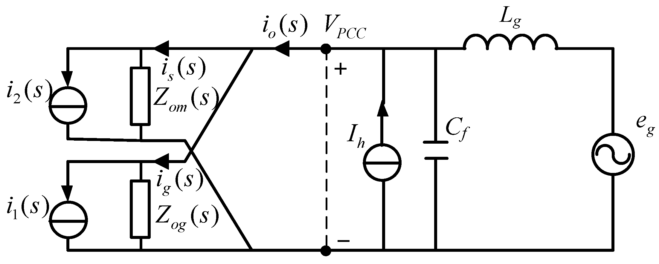
The equivalent impedance model of RSC and DFIG is similar to Figure 5. Zom(s) is the output impedance for the Norton equivalent circuit of RSC and DFIG. The equivalent circuit of DFIG WTS which use current suppression strategy that GSC adopting PIR regulator and RSC adopting the closed-loop control strategy of stator harmonic current based on the rotor current loop with PIR regulator is shown in Figure 7.
3. Harmonic Impact Factor Analysis under Different Control Strategy Conditions
3.1. Harmonic Impact Factor Analysis under Current Suppression Control Conditions
A harmonic current impact factor is defined to analyze the effect of harmonic current source on the total grid-connected current of DFIG WTS. This can be expressed as Equation:
where ZLg is the impedance of the grid inductance, and ZCf is the impedance of the shunt capacitor.
A harmonic voltage impact factor is defined to analyze the effect of harmonic current source on the voltage at PCC, which can be expressed as Equation:
As can be seen from Equations (10) and (11), the harmonic impact factor is not only related to the line impedance and shunt capacitance, but also related to the GSC output impedance and RSC and DFIG output impedance, so when the control strategy changes, the corresponding harmonic factor will change, and the effects of harmonic current sources on DFIG WTS can be changed.
The real harmonic current source is achieved by three-phase uncontrolled rectifier bridge, and the main harmonic order is six times grid frequency in d-q reference frame. Figure 8a shows the bode diagram for harmonic current impact factor of the DFIG WTS in conventional harmonic current suppression mode. The gain at 300 Hz is diminished sharply due to adopting of stator current feedback resonant regulator, which means that 5th and 7th (ABC reference frame) harmonic in the harmonic current source has no effect on total grid-connected current. Figure 8b shows the Bode diagram of harmonic voltage impact factor of DFIG WTS. The gain at 300 Hz is amplified significantly due to the adopted resonant regulator, which means that 5th and 7th harmonics in the harmonic current source has great influence on the voltage at PCC and causes a higher harmonic voltage.
3.2. Harmonic Impact Factor Analysis under Harmonic Voltage Suppression Conditions
The grid code has some requirements governing harmonic voltage at PCC. Harmonic voltage is generated from the interaction between line impedance and harmonic current source. If the converter output harmonic impedance is changed rationally, the harmonic voltage will be diminished. To analyze the influence of impedance ZIH(s) on harmonic voltage and a simplified circuit is shown in Figure 9.
The output total impedance Zo(s) with impedance ZIH(s) connected can be expressed as:
A gain curve for Zo(s) is shown in Figure 10 with different impedances of the resistor Rh and capacitor Ch. As can be seen from Figure 10a, Zo(s) is gradually diminished due to the decreased resistor, and the harmonic voltage caused by the harmonic current source is reduced as follows, which means that the suppression ability of the harmonic voltage is increased. Figure 10b shows that the resonant frequency is dropped with increased capacitor Ch, the gain is attenuated more obviously at the frequencies far away from resonance, which means that the suppression ability of harmonic voltage is also increased. Above all, the resistor can eliminate the resonance peak, the capacitor has a high frequency attenuation ability, so the combination can have a better effect.
The high-frequency components of the voltage at PCC point are extracted by a high-pass filter (HPF in the figures) and divided by virtual harmonic resistor and capacitor as superposition current reference given to ir*. The method used to decrease harmonic voltage is achieved through stator-side virtual harmonic resistor and capacitor, the grid-side converter still retains conventional PIR control. The rotor-side control structure is shown in Figure 11.
The RSC and DFIG equivalent impedance in Figure 11 can be expressed as:
where GHP is the transfer function of high-pass filter:
The equivalent impedance model of DFIG WTS based on the virtual harmonic resistor and capacitor is shown in Figure 12.
According to Figure 12, the harmonic impact factors Equations (10) and (11) are rewritten as follows Equations:
Based on Equations (17) and (18), Figure 13a depicts three amplitude-frequency characteristic curves for the harmonic voltage impact factor with different G4(s) (virtual harmonic resistor, virtual harmonic capacitor and virtual harmonic resistor and capacitor). As can be seen, the harmonic voltage impact factor decreases at 300 Hz with the added virtual harmonic resistor, but the harmonic voltage suppression frequency around 300 Hz is very small and it produces a high amplitude near 300 Hz (slightly larger than 300 Hz). A virtual capacitor can enlarge the frequency range of harmonic voltage suppression at 300 Hz, but meanwhile, it produces a high amplitude near 300 Hz (slightly lower than 300 Hz). The high amplitude of harmonic voltage impact factor near 300 Hz may cause the amplification of the harmonic voltage at the PCC, even causing system instability.
Therefore, a virtual harmonic resistor and capacitor are adopted to enlarge the frequency range of harmonic voltage suppression and decrease the amplitude of the harmonic voltage impact factor near 300 Hz. However, Figure 13b show that the harmonic current impact factor is increased with lower harmonic voltage impact factors, which means that diminished harmonic voltage is achieved by injecting harmonic currents into the grid.
3.3. Harmonic Impact Factor Analysis under Coordinated Suppression Conditions
In summary, if the harmonic voltage is suppressed, the harmonic current will increase, and if the harmonic current is suppressed, the harmonic voltage rise correspondingly. An appropriate state that harmonic voltage and current component will both not too high can be chosen to achieve optimal output grid voltage and grid current to meet the grid code if coordinated factor λ is adopted in Figure 14. The stator equivalent impedance can be rewritten as follows:
Figure 15 shows the overall control block diagram of a coordinated control system, where the grid-side converter works in PIR current suppression mode, and the rotor-side converter remains as the stator harmonic voltage suppression structure while the rotor current reference contains the fundamental current and harmonic current used to change the harmonic voltage. λ is the coordinated factor coefficient, if Rh and Ch is designed to limited harmonic voltage to the bottom, λ can be adjusted to balance the harmonic voltage and harmonic current.
In Figure 16, the virtual harmonic resistor and capacitor will be in the on-state if λ = 1, and harmonic voltage can be suppressed to a minimum, but the harmonic current impact factor gain at 300 Hz is high. Harmonic voltage impact factor gain is increased with decreased coefficient λ, which means that harmonic voltage suppression ability is decreased. Harmonic current impact factor gain is decreased with a decreased coefficient λ, meaning that harmonic current suppression ability is enhanced. When λ = 0.5, the gain of harmonic current and voltage impact factor at 300 Hz are both not too high, thus meeting the grid code.
4. System Stability Analysis
An impedance-based system stability analysis is reported in [25,26], the frequency of the intersection between DFIG converter output impedance of a double-fed wind power generation system and grid impedance in the Bode diagram is the resonant frequency of the whole system, the phase margin can be determined by calculating the phase angle difference between system impedance and grid impedance, so the stability of the system can be obtained.
The output impedance of a double-fed wind power generation system can be expressed as:
The grid impedance is given by:
Figure 17a depicts the Bode diagram of ZDFIG and Zgrid with different virtual harmonic resistors. The phase-differences at the left amplitude-frequency characteristic curves intersection are gradually increased between the system output impedance and grid impedance when the virtual harmonic resistor is diminished. Phase-differences are less than 90°, so the phase margin is large enough to ensure the system stability. As for the right intersection, the phase-difference is 139.6° with virtual harmonic resistor of 1 pu; and the phase-difference is 178.4° with a virtual harmonic resistor of 0.1 pu, which means that the stability of the system is bad, so the value of virtual harmonic resistor should not exceed 0.1 pu. As shown in Figure 17b, when a virtual harmonic capacitor is adopted, the phase-differences at the left of impedance intersection frequency are proportional to the value of the virtual harmonic capacitor. The phase-difference is 87° with a virtual harmonic capacitor of 0.0001 pu; the phase-difference is 145° with a virtual harmonic capacitor of 0.001 pu; and the phase-difference is 173° with a virtual harmonic capacitor of 0.01 pu, which means that the system is no longer stable and the value of virtual harmonic capacitor should not exceed 0.01 pu. In Figure 17c, the virtual harmonic resistor and capacitor have the same characteristics at low frequencies like the virtual harmonic resistor and the same characteristics at high frequencies like the virtual harmonic capacitor. Phase-differences at the left intersection frequency between system output impedance and grid impedance are smaller with a virtual harmonic resistor and capacitor than with a virtual harmonic resistor alone, which means that virtual harmonic resistor and capacitor together have better stability.
5. Experimental Validation
Experimental tests were conducted on a laboratory setup of a 11 kw DFIG system, as shown in Figure 18, where the DFIG is driven by a squirrel cage induction motor working as a wind turbine. A non-linear load is built up to simulate the harmonic grid conditions. The control strategy is implemented on the TI TMS320F28335 (Texas Instruments, Dallas, TX, USA) and the sampling frequency is 8 kHz. Parameters of the tested DFIG are shown in Table 1. All the waveforms are acquired by a YOKOGAWA DL750 scope reader (Yokogawa Electric China Corporation, Suzhou Industrial Park, Jiangsu, China) and DPO3034 (Tektronix, Beaverton, OR, USA), and a Fluke 434 power quality analyzer (Fluke Industrial B.V, Almelo, The Netherlands) is used to measure the contents of each harmonic voltage and current.
The effective value of the rated stator current is 10 A and the total output grid current is 8.9 A. Figure 19a shows the steady performance of the conventional harmonic current suppression. As can be seen in Table 2, the harmonic component of the total harmonic grid current is very low, in which the 5th harmonic component and 7th harmonic component are only 1.8% and 0.4%. On the contrary, the harmonic voltage at PCC is amplified to achieve the current suppression target and 9.5% 5th harmonic component and 2.3% 7th harmonic component form the main harmonic voltage components. In Figure 19b, torque oscillation at 300 Hz is low due to the sinusoidal stator current.
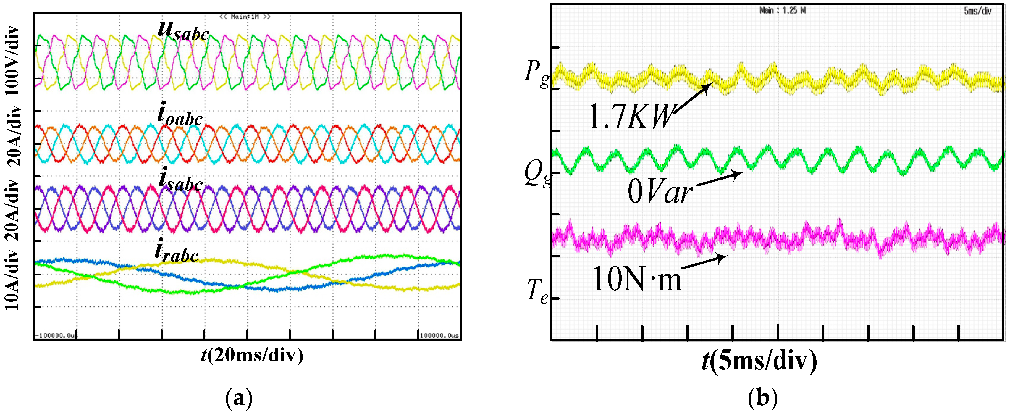
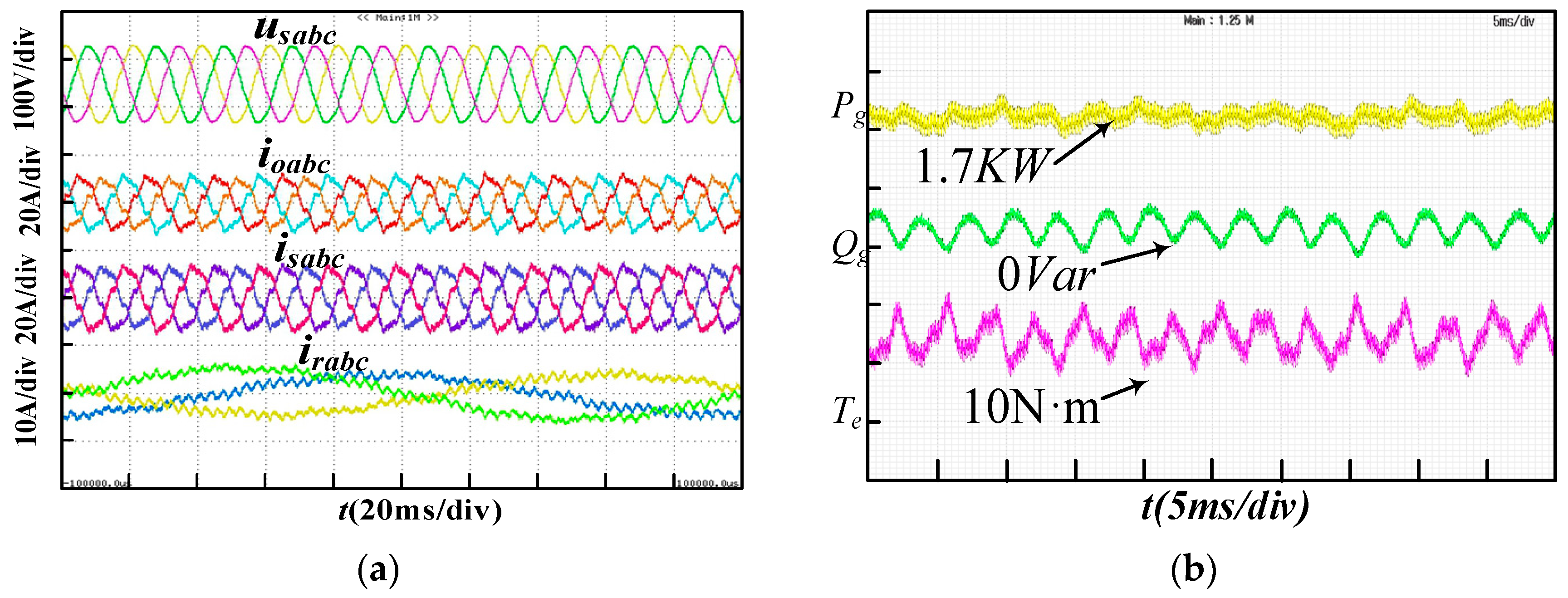
To suppress harmonic voltage at the PCC, a stator-side virtual harmonic resistor and capacitor ares adopted to conduct experiments and generate waveforms as shown in Figure 20, and the harmonic component can be seen in Table 3. The voltage at PCC contains only 2.4% 5th and 0.9% 7th harmonic component which means the harmonic voltage can be damped with the proposed strategy. On the other hand, a harmonic current is generated to achieve less harmonic voltage, so the rotor current and stator current are both high in harmonic components, resulting in a high harmonic total grid current. The total active power Pg and total reactive power Qg oscillation at 300 Hz are low, but torque Te oscillation is high due to the harmonic current.
The coordination factor is adopted to adjust the distribution of harmonic voltage component and harmonic current component, as shown in Figure 21 and Table 4, the THD of voltage and current at PCC are both in a reasonable range. The system performance status can be restructured through coordinated control and the system performance is enhanced.
A virtual harmonic resistor is adopted to suppress harmonic voltages in Figure 22a, a distorted voltage with 4.3% 5th harmonic component and 3.4% 7th harmonic component. The total output grid current is prone to be unstable and a large amount of harmonics are included. In Figure 22b harmonic voltage is further suppressed by use of a virtual harmonic resistor and capacitor. The content of the 5th harmonic voltage only reaches 2.7%, and that of the 7th reaches 0.9%, the voltage at PCC is almost sinusoidal, which means that the virtual harmonic resistor and capacitor can damp harmonic voltages more obviously.
As shown in Figure 23a, with the driving speed increasing from 1450 rpm to 1550 rpm, the rotor current changes from a positive sequence to a negative sequence. Wind speed changes have little impact on the stator voltage and current, and the DFIG WTS can operate stably using the proposed control strategy. In Figure 23b, when the reference instruction of rotor current increases, the current in the stator and rotor increase relevantly and the stator voltage is constant. This verifies that the DFIG WTS can operate steadily when power reference instruction is changed in the proposed control strategy.
6. Conclusions
An impedance-based model of a DFIG system is established, in which a harmonic current source and weak grid are included. A harmonic current impact factor and a harmonic voltage impact factor are introduced to analyze the effect of a harmonic current source on power quality with a capacitive load. Harmonic current sources will cause harmonic current amplification and voltage distortion in double-fed wind power generation systems with capacitive loads, the harmonic current suppression mode exacerbates the harmonic voltage amplification. A stator-side virtual harmonic resistor and capacitor control strategy is adopted to achieve harmonic voltage suppression. Using harmonic voltage suppression, the harmonic voltage at the PCC is evidently decreased but harmonic current amplification is exacerbated. In order to coordinate the harmonic voltage and harmonic current, a coordination factor is proposed to the balance harmonic voltage and current at the PCC. Finally, this paper verified that DFIG WTS can operate steadily when the power setpoint or wind speed change.
Author Contributions
The proposed method and results were carefully discussed by all authors. Z.X. and X.Z. are both the advisors of L.N.
Funding
The authors would like to thank the financial support from the National Key R&D Program of China (2018YFB0904000) and National Nature Science Foundation of China (51877063).
Conflicts of Interest
The authors declare no conflict of interest.
Nomenclature
| io, ig | total output current, grid-side converter output current |
| is, ir | stator current, rotor current |
| VPCC, Usabc | voltage at PCC, stator voltage |
| Lg, Cf, L | grid line impedance, shunt capacitors, filter inductor of GSC |
| Ih | harmonic current source |
| Ts, KPWM | sampling period, modulation gain of pulse-width modulation |
| Kr, ωc, ω0 | the gain of the resonance regulator, the width and the resonance frequency |
| ZLg, ZCf | the impedance of the grid inductance, the impedance of the shunt capacitor |
| ZDFIG, Zgrid | output impedance of DFIG, grid impedance |
| λ | coordinated factor coefficient |
| Pg, Qg, Te | total active power, total reactive power and torque |
| d, q | subscript for component of d and q axis |
References
- Nian, H.; Song, Y. Direct Power Control of Doubly Fed Induction Generator under Distorted Grid Voltage. IEEE Trans. Power Electron. 2014, 29, 894–905. [Google Scholar] [CrossRef]
- Hu, J.; Xu, H.; He, Y. Coordinated Control of DFIG’s RSC and GSC under Generalized Unbalanced and Distorted Grid Voltage Conditions. IEEE Trans. Ind. Electron. 2013, 60, 2808–2819. [Google Scholar] [CrossRef]
- Geng, H.; Liu, C.; Yang, G. LVRT capability of DFIG-Based WECS under asymmetrical grid fault condition. IEEE Trans. Ind. Electron. 2013, 60, 2495–2509. [Google Scholar] [CrossRef]
- Yao, J.; Li, Q.; Chen, Z.; Liu, A. Coordinated Control of a DFIG-Based Wind-Power Generation System with SGSC under Distorted Grid Voltage Conditions. Energies 2013, 6, 2541–2561. [Google Scholar] [CrossRef] [Green Version]
- Zheng, Z.; Yang, G.; Geng, H. Coordinated Control of a Doubly-Fed Induction Generator-Based Wind Farm and a Static Synchronous Compensator for Low Voltage Ride-through Grid Code Compliance during Asymmetrical Grid Faults. Energies 2013, 6, 4660–4681. [Google Scholar] [CrossRef] [Green Version]
- Li, J.; Yao, J.; Zeng, X.; Liu, R.; Xu, D.; Wang, C. Coordinated Control Strategy for a Hybrid Wind Farm with DFIG and PMSG under Symmetrical Grid Faults. Energies 2017, 10, 669. [Google Scholar] [CrossRef]
- Zhou, L.; Liu, J.; Zhou, S. Improved demagnetization control of a doubly-fed induction generator under balanced grid fault. IEEE Trans. Power Electron. 2015, 30, 6695–6705. [Google Scholar] [CrossRef]
- Xiao, S.; Yang, G.; Zhou, H.; Geng, H. An LVRT control strategy based on flux linkage tracking for DFIG-based WECS. IEEE Trans. Ind. Electron. 2013, 60, 2820–2832. [Google Scholar] [CrossRef]
- Sun, D.; Wang, X. Low-Complexity Model Predictive Direct Power Control for DFIG under Both Balanced and Unbalanced Grid Conditions. IEEE Trans. Ind. Electron. 2016, 63, 5186–5196. [Google Scholar] [CrossRef]
- Yao, J.; Li, H.; Chen, Z.; Xia, X.; Chen, X.; Li, Q.; Liao, Y. Enhanced control of a DFIG-based wind-power generation system with series grid-side converter under unbalanced grid voltage conditions. IEEE Trans. Power Electron. 2013, 28, 3167–3181. [Google Scholar] [CrossRef]
- Huang, Q.; Zou, X.; Zhu, D.; Kang, Y. Scaled Current Tracking Control for Doubly Fed Induction Generator to Ride-Through Serious Grid Faults. IEEE Trans. Power Electron. 2016, 31, 2150–2165. [Google Scholar] [CrossRef]
- Song, Y.; Nian, H. Modularized control strategy and performance analysis of DFIG system under unbalanced and harmonic grid voltage. IEEE Trans. Power Electron. 2015, 30, 4831–4842. [Google Scholar] [CrossRef]
- Liu, C.; Blaabjerg, F.; Chen, W.; Xu, D. Stator current harmonic control with resonant controller for doubly fed induction generator. IEEE Trans. Power Electron. 2012, 27, 3207–3220. [Google Scholar] [CrossRef]
- IEEE Recommended Practices and Requirements for Harmonic Control in Electric Power Systems. Available online: https://ieeexplore.ieee.org/document/6826459/ (accessed on 23 September 2018).
- Xu, H.; Hu, J.; He, Y. Operation of Wind-Turbine-Driven DFIG systems under distorted grid voltage conditions: Analysis and Experimental Validations. IEEE Trans. Power Electron. 2012, 27, 2354–2366. [Google Scholar] [CrossRef]
- Xu, H.; Hu, J.; He, Y. Integrated Modeling and Enhanced Control of DFIG under Unbalanced and Distorted Grid Voltage Conditions. IEEE Trans. Energy Convers. 2012, 27, 725–736. [Google Scholar] [CrossRef]
- Phan, V.; Lee, H. Performance Enhancement of Stand-Alone DFIG Systems with Control of Rotor and Load Side Converters Using Resonant Controllers. IEEE Trans. Ind. Appl. 2012, 48, 199–210. [Google Scholar] [CrossRef]
- Hu, J.; He, Y. Reinforced Control and Operation of DFIG-Based Wind-Power-Generation System under Unbalanced Grid Voltage Conditions. IEEE Trans. Energy Convers. 2009, 24, 905–915. [Google Scholar] [CrossRef]
- Lascu, C.; Asiminoaei, L.; Boldea, I.; Blaabjerg, F. High performance current controller for selective harmonic compensation in active power filters. IEEE Trans. Power Electron. 2007, 22, 1826–1835. [Google Scholar] [CrossRef]
- Phan, V.; Lee, H. Control Strategy for harmonic elimination in stand-alone DFIG applications with nonlinear loads. IEEE Trans. Power Electron. 2011, 26, 2662–2675. [Google Scholar] [CrossRef]
- Song, Y.; Wang, X.; Blaabjerg, F. Doubly Fed Induction Generator System Resonance Active Damping through Stator Virtual Impedance. IEEE Trans. Ind. Electron. 2017, 64, 125–137. [Google Scholar] [CrossRef] [Green Version]
- Stratford, R.P. Rectifier Harmonics in Power Systems. IEEE Trans. Ind. Appl. 1980, IA-16, 271–276. [Google Scholar] [CrossRef]
- Peng, F.Z. Harmonic sources and filtering approaches. IEEE Ind. Appl. Mag. 2001, 7, 18–25. [Google Scholar] [CrossRef]
- Song, Y.; Wang, X.; Blaabjerg, F. Impedance-Based High Frequency Resonance Analysis of DFIG System in Weak Grids. IEEE Trans. Power Electron. 2017, 32, 3536–3548. [Google Scholar] [CrossRef]
- Sun, J. Impedance-based stability criterion for grid-connected inverters. IEEE Trans. Power Electron. 2011, 26, 3075–3078. [Google Scholar] [CrossRef]
- Song, Y.; Wang, X.; Blaabjerg, F. High-Frequency Resonance Damping of DFIG-Based Wind Power System Under Weak Network. IEEE Trans. Power Electron. 2017, 32, 1927–1940. [Google Scholar] [CrossRef]
Figure 1.
Block diagram of the DFIG control system under nonlinear load conditions.

Figure 2.
Equivalent model of weak grid with nonlinear load.
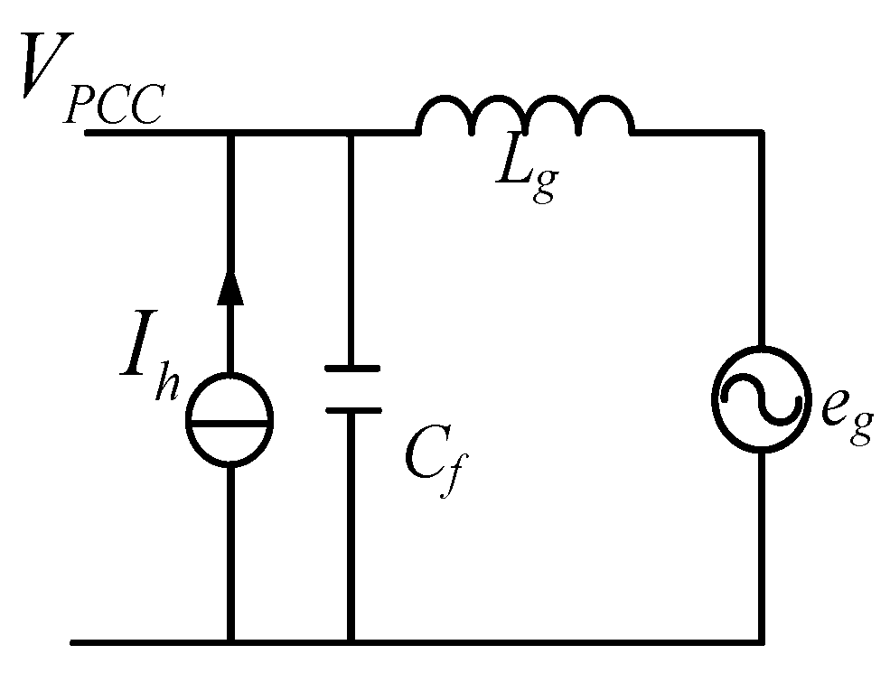
Figure 3.
Harmonic spectrum of a harmonic current source based on Fast Fourier Transformation (FFT) analysis.
Figure 3.
Harmonic spectrum of a harmonic current source based on Fast Fourier Transformation (FFT) analysis.

Figure 4.
The equivalent structure diagram of GSC with PIR regulator.

Figure 5.
Equivalent impedance model of GSC and L-filter.
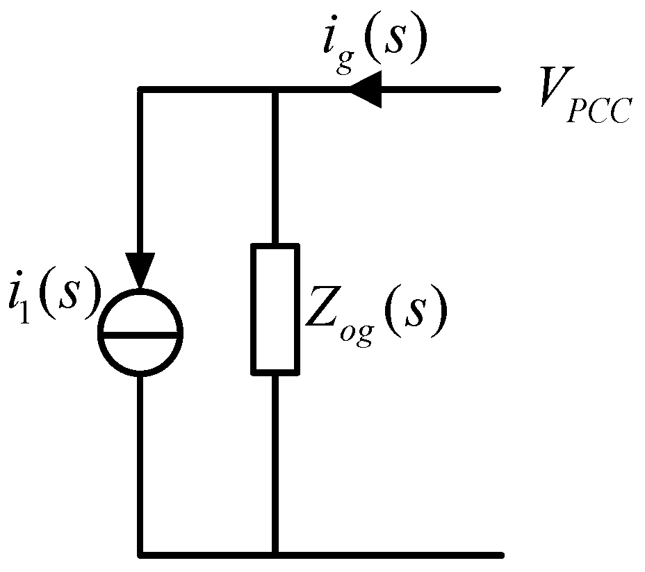
Figure 6.
The equivalent structure diagram of stator harmonic current closed-loop control strategy.

Figure 7.
Equivalent impedance model of DFIG WTS.

Figure 8.
Harmonic impact factor of DFIG WTS under harmonic current suppression conditions. (a) Harmonic current impact factor of DFIG WTS; (b) Harmonic voltage impact factor of DFIG WTS.
Figure 8.
Harmonic impact factor of DFIG WTS under harmonic current suppression conditions. (a) Harmonic current impact factor of DFIG WTS; (b) Harmonic voltage impact factor of DFIG WTS.
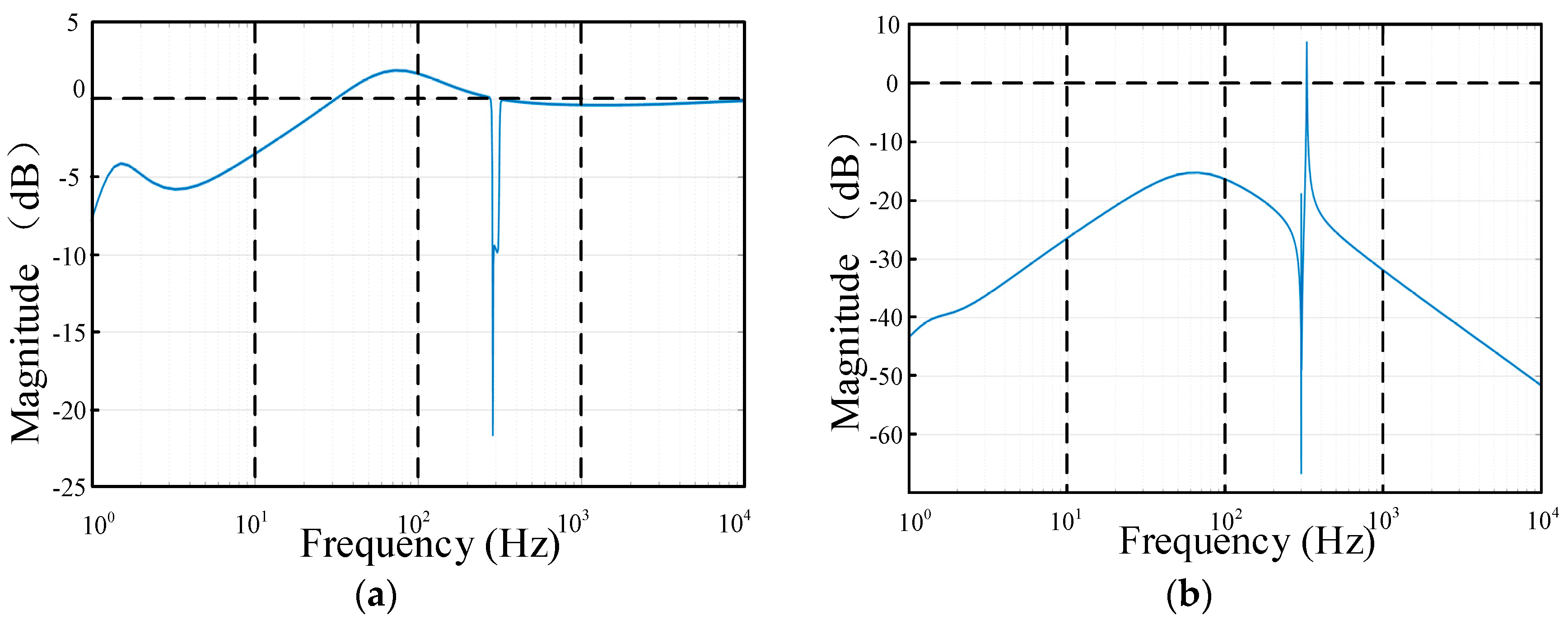
Figure 9.
Simplified circuit diagram with the impedance changed.

Figure 10.
Bode diagram of Zo(s) with impedance changed. (a) Zo(s) with different resistors; (b) Zo(s) with different capacitors.
Figure 10.
Bode diagram of Zo(s) with impedance changed. (a) Zo(s) with different resistors; (b) Zo(s) with different capacitors.
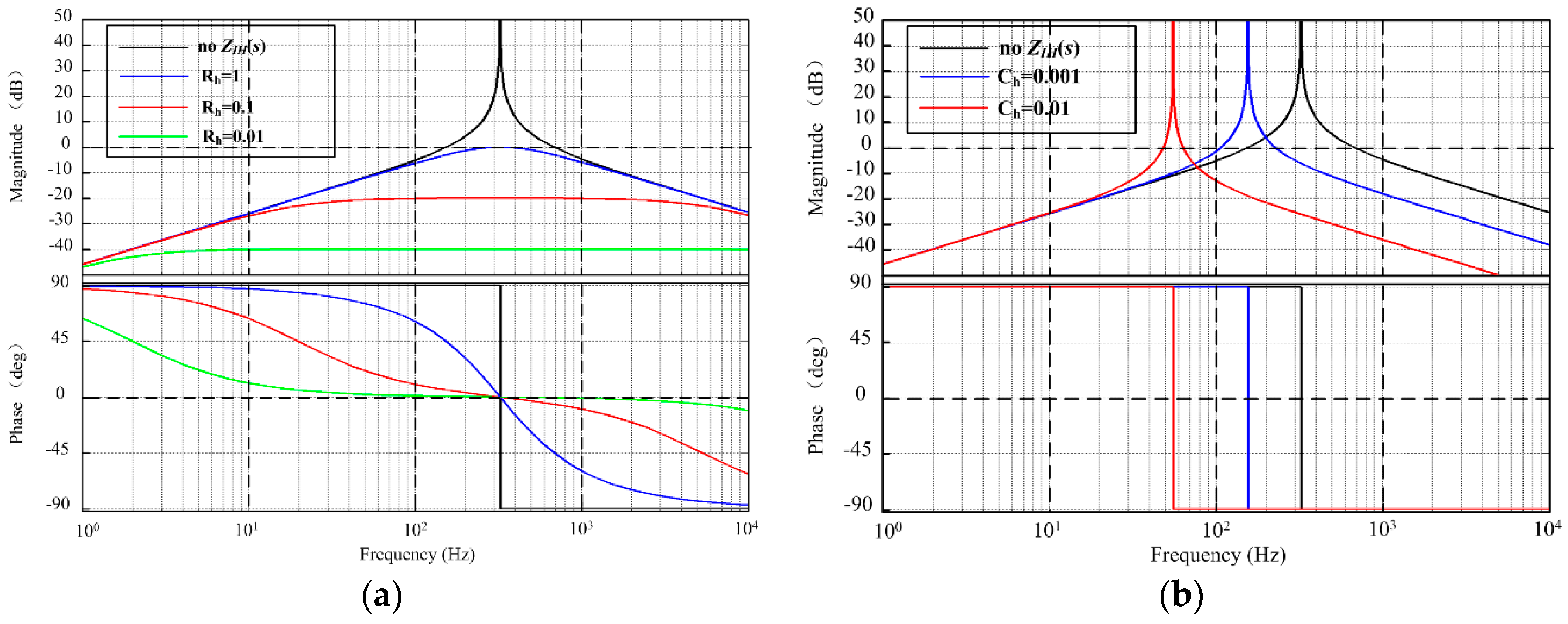
Figure 11.
Block diagram of the closed-loop control system for RSC and DFIG based on the virtual harmonic resistor and capacitor.
Figure 11.
Block diagram of the closed-loop control system for RSC and DFIG based on the virtual harmonic resistor and capacitor.

Figure 12.
Equivalent impedance model of DFIG WTS based on the virtual harmonic resistor and capacitor.
Figure 12.
Equivalent impedance model of DFIG WTS based on the virtual harmonic resistor and capacitor.

Figure 13.
Harmonic impact factor with stator-side virtual harmonic impedance. (a) Harmonic voltage impact factor; (b) Harmonic current impact factor.
Figure 13.
Harmonic impact factor with stator-side virtual harmonic impedance. (a) Harmonic voltage impact factor; (b) Harmonic current impact factor.
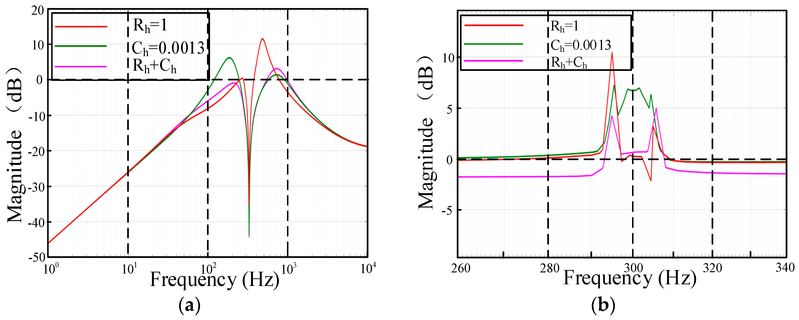
Figure 14.
Block diagram of the closed-loop control system for RSC and DFIG based on the virtual harmonic resistor and capacitor with coordinated factor.
Figure 14.
Block diagram of the closed-loop control system for RSC and DFIG based on the virtual harmonic resistor and capacitor with coordinated factor.

Figure 15.
Block diagram of DFIG control system based on coordinated control.

Figure 16.
Harmonic impact factor with coefficient λ changed. (a) Harmonic voltage impact factor with coefficient λ changed; (b) Harmonic current impact factor with coefficient λ changed.
Figure 16.
Harmonic impact factor with coefficient λ changed. (a) Harmonic voltage impact factor with coefficient λ changed; (b) Harmonic current impact factor with coefficient λ changed.

Figure 17.
The Bode diagram of ZDFIG and Zgrid at different virtual harmonic impedances. (a) The bode diagram for different virtual harmonic resistors; (b) The bode diagram for different virtual harmonic capacitors; (c) The bode diagram with virtual harmonic resistor and capacitor group.
Figure 17.
The Bode diagram of ZDFIG and Zgrid at different virtual harmonic impedances. (a) The bode diagram for different virtual harmonic resistors; (b) The bode diagram for different virtual harmonic capacitors; (c) The bode diagram with virtual harmonic resistor and capacitor group.

Figure 18.
Simplified experimental set-up: the DFIG system.

Figure 19.
The experimental waveform under harmonic current suppression conditions. (a) Waveform of stator line voltage usabc, total grid current ioabc, stator current isabc and rotor current irabc; (b) Waveform of total active power Pg, total reactive power Qg and torque Te.
Figure 19.
The experimental waveform under harmonic current suppression conditions. (a) Waveform of stator line voltage usabc, total grid current ioabc, stator current isabc and rotor current irabc; (b) Waveform of total active power Pg, total reactive power Qg and torque Te.

Figure 20.
The harmonic voltage suppression experimental waveform on the rotor side. (a) Waveform of stator line voltage usabc, total grid current ioabc, stator current isabc and rotor current irabc, (b) Waveform of total active power Pg, total reactive power Qg and torque Te.
Figure 20.
The harmonic voltage suppression experimental waveform on the rotor side. (a) Waveform of stator line voltage usabc, total grid current ioabc, stator current isabc and rotor current irabc, (b) Waveform of total active power Pg, total reactive power Qg and torque Te.

Figure 21.
The experimental waveform under coordinated control conditions. (a) Waveform of stator line voltage usabc, total grid current ioabc, stator current isabc and rotor current irabc; (b) Waveform of total active power Pg, total reactive power Qg and torque Te.
Figure 21.
The experimental waveform under coordinated control conditions. (a) Waveform of stator line voltage usabc, total grid current ioabc, stator current isabc and rotor current irabc; (b) Waveform of total active power Pg, total reactive power Qg and torque Te.

Figure 22.
The experimental waveform with virtual harmonic impedance changed. (a) Waveform of virtual harmonic resistor; (b) Waveform of virtual harmonic resistor and capacitor.
Figure 22.
The experimental waveform with virtual harmonic impedance changed. (a) Waveform of virtual harmonic resistor; (b) Waveform of virtual harmonic resistor and capacitor.

Figure 23.
The experimental waveform with speed and power changed under the proposed control strategy. (a) Waveform of wind speed changed; (b) Waveform of stator power changed.
Figure 23.
The experimental waveform with speed and power changed under the proposed control strategy. (a) Waveform of wind speed changed; (b) Waveform of stator power changed.


Table 1.
Parameters of the DFIG system.
| Parameter | Value |
|---|---|
| Rated power | 11 kW |
| Rated speed | 1475 r/min |
| Stator and rotor rated voltage | 380 V, 858 V |
| Stator and rotor rated current | 17.6 A, 8.1 A |
| Stator and rotor resistance | 0.2858 Ω, 0.2983 Ω |
| Stator and rotor inductance | 0.068923 H, 0.069381 H |
| Mutual inductance | 0.0676 H |
| Number of pole pairs | 2 |
| Simulation grid impedance | 0.8 mH, 300 μF |
| Filter inductor L | 4 mH |
| Filter inductor Lr | 0.5 mH |
Table 2.
THD of voltage and current at PCC under conventional harmonic current suppressions condition.
Table 2.
THD of voltage and current at PCC under conventional harmonic current suppressions condition.
| Harmonic Voltage at PCC | Component (%) | Harmonic Current at PCC | Component (%) |
|---|---|---|---|
| THD | 9.9 | THD | 4.3 |
| 5th harmonics | 9.5 | 5th harmonics | 1.8 |
| 7th harmonics | 2.3 | 7th harmonics | 0.4 |
Table 3.
THD of voltage and current at PCC under harmonic voltage suppression condition.
| Harmonic Voltage at PCC | Component (%) | Harmonic Current at PCC | Component (%) |
|---|---|---|---|
| THD | 3.3 | THD | 10.6 |
| 5th harmonics | 2.4 | 5th harmonics | 9.0 |
| 7th harmonics | 0.9 | 7th harmonics | 2.8 |
Table 4.
THD of voltage and current at PCC under coordinated control condition.
| Harmonic Voltage at PCC | Component (%) | Harmonic Current at PCC | Component (%) |
|---|---|---|---|
| THD | 6.6 | THD | 7.0 |
| 5th harmonics | 6 | 5th harmonics | 5.6 |
| 7th harmonics | 1.7 | 7th harmonics | 1.0 |
© 2018 by the authors. Licensee MDPI, Basel, Switzerland. This article is an open access article distributed under the terms and conditions of the Creative Commons Attribution (CC BY) license (http://creativecommons.org/licenses/by/4.0/).
Share and Cite
MDPI and ACS Style
Xie, Z.; Niu, L.; Zhang, X. An Enhanced Control Strategy for Doubly-Fed Induction Generators Based on a Virtual Harmonic Resistor and Capacitor under Nonlinear Load Conditions. Energies 2018, 11, 2613. https://doi.org/10.3390/en11102613
AMA Style
Xie Z, Niu L, Zhang X. An Enhanced Control Strategy for Doubly-Fed Induction Generators Based on a Virtual Harmonic Resistor and Capacitor under Nonlinear Load Conditions. Energies. 2018; 11(10):2613. https://doi.org/10.3390/en11102613
Chicago/Turabian StyleXie, Zhen, Lifan Niu, and Xing Zhang. 2018. "An Enhanced Control Strategy for Doubly-Fed Induction Generators Based on a Virtual Harmonic Resistor and Capacitor under Nonlinear Load Conditions" Energies 11, no. 10: 2613. https://doi.org/10.3390/en11102613
Note that from the first issue of 2016, this journal uses article numbers instead of page numbers. See further details here.