Distributed Control Strategy for DC Microgrids of Photovoltaic Energy Storage Systems in Off-Grid Operation


School of Automation Science and Electrical Engineering, Beihang University, Beijing 100191, China
*
Author to whom correspondence should be addressed.
†
These authors contributed equally to this work.
Energies 2018, 11(10), 2637; https://doi.org/10.3390/en11102637
Submission received: 27 August 2018
/
Revised: 27 September 2018
/
Accepted: 27 September 2018
/
Published: 2 October 2018
Abstract
:DC microgrid systems that integrate energy distribution, energy storage, and load units can be viewed as examples of reliable and efficient power systems. However, the isolated operation of DC microgrids, in the case of a power-grid failure, is a key factor limiting their development. In this paper, we analyze the six typical operation modes of an off-grid DC microgrid based on a photovoltaic energy storage system (PV-ESS), as well as the operational characteristics of the different units that comprise the microgrid, from the perspective of power balance. We also analyze the key distributed control techniques for mode transformation, based on the demands of the different modes of operation. Possible reasons for the failure of PV systems under the control of a voltage stabilizer are also explored, according to the characteristics of the PV output. Based on this information, we propose a novel control scheme for the seamless transition of the PV generation units between the maximum PV power tracking and steady voltage control processes, to avoid power and voltage oscillations. Adaptive drooping and stabilization control of the state of charge of the energy storage units are also considered, for the protection of the ESS and for reducing the possibilities of overcharging and/or over-discharging. Finally, various operation conditions are simulated using MATLAB/Simulink, to validate the performance of the proposed control strategy.
1. Introduction
Microgrid structures consisting of multiple intelligently coordinated heterogeneous networks have greatly improved the operation of power grids [1]. These structures have been widely studied as basic units that can be integrated into a larger overall network [2,3,4,5]. DC microgrids, as an alternative option, have been attracting increasing interest in the recent years, owing to their advantages of high system power quality and easy control with neither reactive power nor AC harmonic concerns.
However, the power quality of microgrids is influenced by the fluctuation and intermittence of renewable distributed micro-power. A potential solution is utilizing energy storage systems (ESSs) in order to alleviate the problem in microgrids. Hence, research on control and management technologies relevant to DC microgrids has become increasingly prevalent.
Most of the DC microgrid research conducted so far has focused on the control, operation and power sharing of DGs in an DC microgrid during and subsequent to islanding. A control strategy was developed for autonomous DC microgrids, applicable to low-voltage applications such as remote telecommunication power systems; experimental tests on changing the mode conditions showed seamless transitions between system-level modes [2]. The control technique proposed in [3] enabled maximum utilization of photovoltaic (PV) power during the different operating conditions of the microgrid and provided a seamless transfer between the grid-connected and islanded modes. PV energy storage DC microgrids comprising distributed PV generation units, energy storage batteries, power electronic conversion devices, and load devices, typically have two stable modes of operation, the grid-connected mode and the off-grid mode [6,7,8]. System control for dc microgrids with variable generations and energy storage is proposed in this paper in [9], an autonomous control strategy based on the DC voltage variations in a DC microgrid with various sources and loads was proposed. In this strategy, the system control was divided into three levels according to the DC voltage variation. The operational modes and control strategies for distributed generators (DGs) and ESSs were analyzed, and the flexibility and reliability of the control strategy for a hybrid microgrid was verified. A modified distributed control method for mesh and radial configurations was proposed and analyzed in [10], in which a low-bandwidth communication controller was used to exchange voltage and current information between different converters in the DC microgrid. The influence of communication delay on the stability was also analyzed, and it was demonstrated that the designed controller had a plug-and-play function. A set of feasible energy management and control strategies for the stable operation of DC/AC microgrids was proposed, based on the typical topologies of microgrids of renewable energy sources. The ESS was utilized to maintain the power balance between the PV power supply and load demand in the off-grid mode [11]. In [12], a master–slave-based control strategy for a PV energy storage microgrid system was studied. An improved low-bandwidth communication (LBC)-based droop control method and a load current sharing control strategy for parallel DC/DC converters was proposed, to solve the current sharing control problem during the interconnected communication between power generators in a DC microgrid in [13,14].
The operating modes of DC microgrid are generally divided into grid-connected and off-grid mode. PV power sources are expected to work in maximum power tracking technology (MPPT) and deliver the maximum available power to the grid in grid-connected mode. However, under the off-grid mode, in order to increase energy utilization efficiency of the DC microgrid, PV power is required to operate in MPPT mode as well, such as supplying power to both the load and the energy storage system. According to the characteristic voltage–power (U–P) curves of a typical generator, the output of a PV module is nonlinear. Reference [15] illustrated the intermittency of PV output, caused by changes in the PV module environment. To exploit this, the maximum power tracking technology (MPPT) was introduced, to increase the output of the PV modules. In [16,17], an improved perturb and observe (P&O) scheme based on the traditional MPPT algorithm was proposed, to improve the efficiency of tracking in the dynamic and steady states. The development of artificial intelligence technologies made the application of artificial neural networks (ANN) and nonlinear control technologies to the maximum power tracking process possible, as described in [18,19,20].
To overcome the influence of the intermittency and volatility of PV power, and better balance the power relationship between PV modules, grids, and loads, ESSs have been widely applied in PV-based DC microgrids, to ensure reliable and stable operation. Multiple studies have been conducted on the control strategies, power allocation modes, optimization, and economic operation of ESSs for microgrids. For example, a cascade PI controller based on the Lyapunov criterion was detailed in [21], where power allocation between different ESSs proceeded on the premise of ensuring the stability of the controllers. In [22], a fast-response integral droop (ID) that effectively distributed transient power in a hybrid ESS controller was designed. The use of a two-quadrant energy storage controller for power allocation among multiple batteries, to increase their lifespans, was discussed in [23,24].
So far, very few studies have focused on operation mode characterization, mode transformation control technologies, and independent PV distribution under ESS protection, for DC microgrids in the off-grid mode. This paper aims to solve the above limitations by considering the independent operation mode of DC microgrids. First, we define the typical structure of a PV energy storage DC microgrid in the off-grid operation, as shown in Figure 1. The characteristics of the operation modes and transformation boundaries for the PV generation units, ESSs, and loads are then analyzed. Based on these modes of operation, we discuss the key control technologies for each unit of a PV-ESS DC microgrid. The failure of PV power generation in stabilizing voltage control is also analyzed. Using this information, we propose a seamless transfer controller for PV generator units, for the transfer between MPPT and voltage regulation. Finally, we build a PV energy storage DC microgrid model, for the simulation and verification of the proposed mode conversion and control methods.
The remainder of this paper is organized as follows. In Section 2, the structure, operating modes, and modal transitions of a PV energy storage DC microgrid are discussed. The key control problems of the PV-ESS in DC microgrids are studied in Section 3, based on the operational mode analysis. This includes an analysis of the output characteristics of a PV system, the “failure mechanism” of PV voltage stabilization, and the feasibility of multi-unit energy storage and voltage stabilization in a controller for the seamless transfer between MPPT and voltage regulation. We also consider a droop stabilizing controller for stabilizing the state of charge (SOC) of the energy storage units. Section 4 details the simulations performed to verify the effectiveness of the proposed method under various working conditions. The conclusions of this paper are summarized in Section 5.
2. Structure and Operation Modes of DC Microgrid Systems
2.1. Composition of a DC Microgrid
DC microgrids typically consist of DGs, ESSs, and loads, connected by DC buses. Two operating modes, grid-connected mode and off-grid mode, can be defined for these systems, according to whether they are connected to large power grids or not. The structure of a typical PV-ESS DC microgrid in off-grid operation is shown in Figure 2.
From Figure 2, it can be seen that the power generators, which are the PV modules in this case, are connected to the DC bus through a one-way DC/DC converter (the image details a buck–boost conversion scheme) and DC circuit breaker. As PV power generation is intermittent and volatile, the fluctuation of the PV output should be stabilized, to reduce the impact of this uncertainty on the grid. Thus, it is necessary to configure energy storage devices in a PV-ESS DC microgrid, to maintain a steady voltage and ensure that the power between the source and load is balanced.
The intermittency of PV power, the residual energy states of the ESSs, the load units, and the disturbances from faults affect the power balance and energy flow in a PV-ESS DC microgrid, and thus determine the control mode of the power electronic converter in a DC microgrid. Hence, it is particularly important to research the operation modes, modal boundaries, and modal transformations of DC microgrids in the off-grid operation.
2.2. Operation Modes of a DC Microgrid
The operating conditions of PV-ESS DC microgrids can be categorized into six modes, according to the structure illustrated in Figure 2. The operation modes and the conditions for transition between these are summarized in Figure 3.
The maximum PV power, denoted as Pmaxpv in Figure 3, depends on the power required for storing energy at a particular SOC, the PV output, and the load. The PV-ESS DC microgrid operates in one of six modes, according to the control strategy, ESS state, and load conditions. That is: the control strategy for the PV generation unit can be MPPT or a voltage regulation. The ESSs can be operated in the voltage regulation or charge/discharge states, or in the shutdown state. Finally, the load can be increased, decreased, or in special cases, removed. The six different modes are described below:
Mode I: In this condition, Pmaxpv is less than the load power, and the SOC of the ESS is lower than the preset minimum. The storage system is in the SOC protection state, and the bidirectional DC/DC converter turns off the ESS, to prevent over-discharge and maintain the life of the ESS. To maintain the power balance of the DC microgrid and ensure voltage stability, a partial load is removed.
Mode II: The microgrid system transitions to this condition from Mode I. Here, Pmaxpv is greater than the load power and the PV unit is controlled in the MPPT mode. In the ESS, the DC bus voltage is stabilized by the bidirectional DC/DC converter. The PV module supplies power to the load, and the residual power is used to charge the ESS, the SOC of which is still below the preset minimum.
Mode III: During the transition from Mode II to Mode III, the ESS is charged continuously, and the SOC rises. The working conditions are as in the case of Mode II: the PV output power is larger than the load, the PV unit is controlled in the MPPT mode, and the ESS maintains the DC bus voltage through the two-way DC/DC converter. However, the SOC of the ESS will be in the normal range, between SOCmax and SOCmin, unlike in Mode II.
Mode IV: The operational conditions of Mode IV are similar to those of Mode III. However, in this case, the load is increased (or the irradiance on the PV module is decreased). Hence, Pmaxpv is less than the load power. Although the generation unit is still controlled using an MPPT strategy, the energy storage converter controls the DC voltage and the ESS will be in the discharge state. The SOC of the ESS declines, as a result.
Mode V: In this state, as in Mode III, Pmaxpv is larger than the load power. The energy storage battery is charged beyond the upper limit, SOCmax. In this situation, to protect the battery life and avoid overcharging the batteries, the energy storage converter is stopped from operating. The PV module supplies power to the load independently, and the PV control strategy is changed from MPPT to voltage regulation.
Mode VI: If the load is increased or the irradiance is decreased when the microgrid system is in Mode V, the magnitude of Pmaxpv will be insufficient to meet the load demand. The control strategy for the PV module thus switches from voltage regulation to MPPT, to ensure that maximum power is generated. The remaining power required by the load is supplied by the energy storage unit, to make up for the shortfall; and the energy storage converter switches from the standby state to an operational state, to maintain the stability of the DC bus voltage.
From the above analyses, it can be concluded that the modal boundary definitions are based on the maximum possible output power of a PV module, the charge state of the energy storage unit, and the power required by the load. The two primary reasons for defining the operational modes in this manner are to stabilize the voltage of the DC bus for ensuring reliable operation of the grid while supplying load power and to extend the life of the energy storage units while maximizing the potential generation of PV energy. The key control techniques for maintaining internal mode evolution or transition to different modes depend on the maximum PV power output algorithm, stable PV DC bus voltage, and performance of the technology controlling the stable DC bus voltage, in consideration of the protection of the energy storage units.
3. Characteristics of PV Modules and Energy Storage Units Used for Controller Design
The analysis presented in Section 2 demonstrates that switching between the different modes of operation corresponds to modifying the electronic power converter modes in the PV modules and ESS units. Hence, studying control strategies for switching between the different modes of operation of the PV converter and the energy storage unit converter is very important.
3.1. Analysis of Output Characteristics and Failure Mechanism of PV Modules
There have been numerous studies on maximum power tracking algorithms for PV systems, the findings of which have been widely used in the design of microgrid systems. In this study, we consider a traditional P&O algorithm. Based on PV nonlinear output characteristics, we discuss the feasibility of stabilizing the DC bus voltage of the PV modules in a PV-ESS grid in Mode V of off-grid operation, detailed in Figure 3, using the analysis process illustrated in Figure 4. At the maximum power point C, the power is given by Pmax, while the output voltage is Um. Also depicted are four different working points, A, B, D, and E, where the output voltages are UA, UB, UD, and UE, respectively.
For analyzing the failure of PV voltage regulation, the characteristic output curve in Figure 4 is segmented by three load lines. To illustrate the causes for the failure of the constant voltage control mechanism in the PV power generation unit, we discuss two load conversion scenarios.
- (1)
- Scenario 1: load power is increased from P1 to P2.There are two points on the U–P curve illustrated in Figure 4, which correspond to an output power of P1, A and E. Regulation at these points is discussed below.
- (1.1)
- In this sub-scenario, we assume that the power generation system is at point A. The DC bus voltage falls temporarily as the power demand increases from P1 to P2. Owing to the steady voltage control algorithm, an increase in the load power results in an increase in the output PV current. The positive error signal, obtained by subtracting the output voltage of the DC bus from the required voltage, is sent to the double loop controller, and the duty cycle of the converter is subsequently increased. A steady-state condition is reached at point B, and DC bus voltage stability is achieved.
- (1.2)
- In this sub-scenario, the power generation system is at point E. As before, the DC bus voltage falls temporarily as the load is increased, and the processing of the positive error signal by the double loop controller causes the duty ratio to increase, to keep the DC bus voltage constant. Increasing the duty cycle and output PV current shifts the operating point of the generation system to the left. However, as point E is located to the left of the maximum power point, reducing the voltage of the PV system will reduce the output PV power, leading to an increase in the positive error. This, in return, aggravates the left shift of the working point, forming a direct connection in the switching transistor. The working point eventually slides to point 0, and the PV system will fall into a short-circuit state, causing the voltage stabilization technique to fail.
- (2)
- Scenario 2: load power is increased from P1 to P3
In this scenario, the generation system is at point A. As before, increasing the power demand (from P1 to P3) leads to a transient drop in the DC bus voltage. The positive error signal resulting from this change in voltage is sent to the double loop controller, which causes the duty cycle to increase. Because of regulation, the power generation system will eventually reach point C, where the maximum power is generated. However, as P3 is greater than C, the DC bus voltage will still be lower than the required value and the double loop controller will continue working. Therefore, the working point will pass point C, and the increase in the duty cycle will reduce the output power. Further regulation will move the working point to the left, leading to the direct connection of the switching transistor, and the PV module falls into a short-circuit state, causing a regulation failure. Similarly, if the initial working point of the generation system is E, the voltage regulation system will cause the final working point to move to point 0, forming a PV short circuit, leading to the failure of the voltage stabilization control.
From the above analyses, we observe that there are two feasible points of operation, on the left and right sides of the maximum power point on the U–P curve, when Pload < Pmax. When the load is increased, the working point of the generation system inevitably slides to the left. If the initial working point is on the left side of the maximum power point, this slide to the left will eventually result in a regulation failure. Therefore, under voltage stabilization control, the initial working point of the voltage regulator should be located on the right side of the maximum power point of the U–P curve, so that the PV module can support the load to complete the stabilization process. If the load power is increased to a value that is greater than the maximum power output of the PV module, a part of the load must be allocated to the completion of the stabilization process. Hence, if the PV power is guaranteed to be larger than the load power, and the PV working range is limited to the right side of the maximum power point, the strategy of independent PV voltage stabilization will be feasible.
Based on the monotonic variation of the output PV current with respect to voltage, as depicted in the U–I curve in Figure 5, and the idea of dual loop control, we propose an anti-dead zone control method to limit the amplitude of the nominal value of the inner current loop. This method restricts the voltage and output power of the PV to the right side of the maximum power point, to avoid regulation failure, as illustrated in Figure 5.
Since the output characteristics of the PV unit depend primarily on the irradiance intensity and temperature, we use the maximum power point current im, at the test conditions provided by the manufacturers of the PV panel, to define the amplitude limit for the inner current loop, to ensure that stabilization can be achieved at different irradiance and temperature conditions. The method limits the reference value of the inner current loop to prevent the PV operating point from entering the left side of the MPP curve during regulation. At the same time, considering the changes in irradiance and temperature adaptively changes the inner loop reference value. In accordance with the PV array characteristics (Figure 5b), the MPP locus, i.e., MPPs at different radiation levels, can be approximated by a cubic function. It is worth noting that, in order to keep the working point on the right side of the maximum power point, as much as possible, the limiting amplitude should be set to a value slightly less than im.
3.2. Seamless Transfer Controller
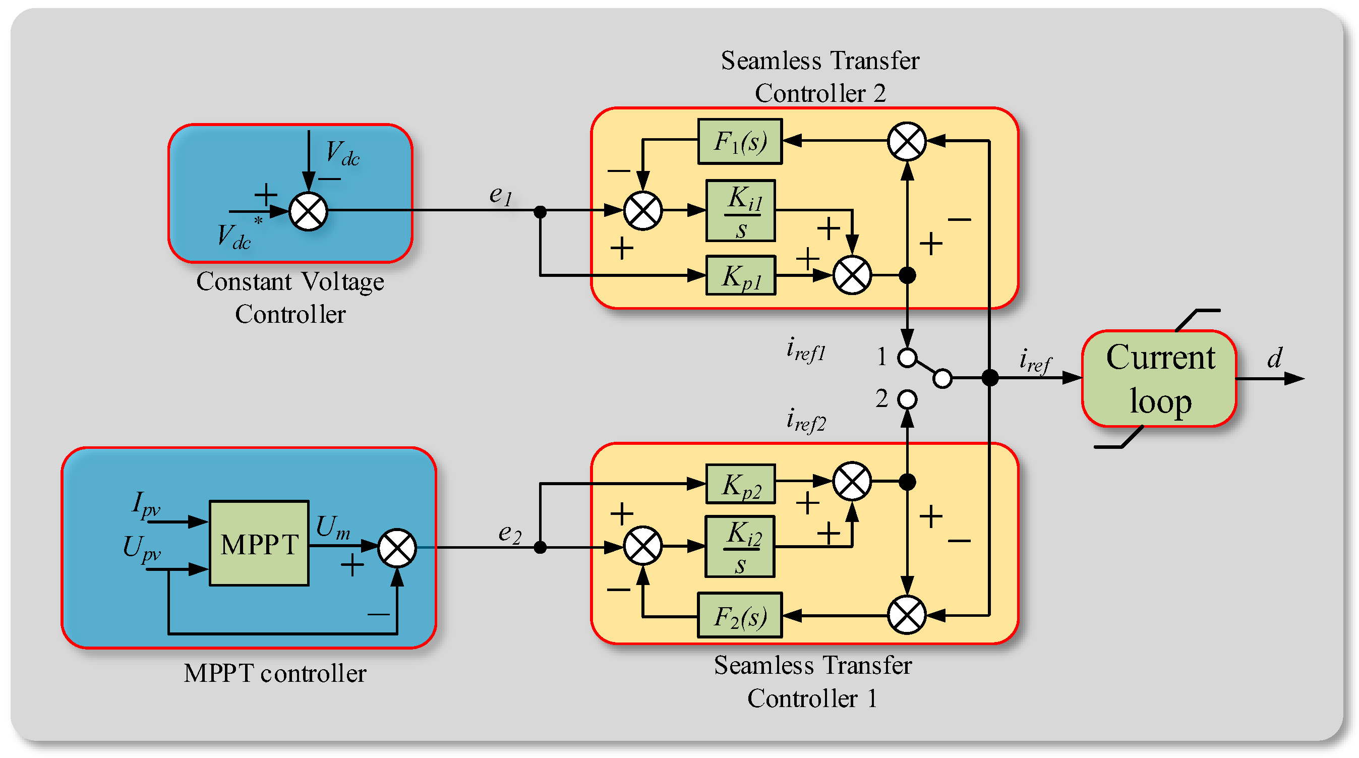
Based on analysis of the feasibility of independent DC bus voltage stabilization and the operation mode of PV-ESS DC microgrids, it is found that there are two different sets of requirements for PV output control during the transitions from Mode III to V and Mode V to VI. A block diagram of the control system is shown in Figure 6.
A comparison of the voltage regulator and the MPPT controller depicted in Figure 6 reveals that they both use a dual loop control structure. The difference lies in the output of the outer ring—although the nominal value of the inner current ring is different, a common inner current loop can simplify the design of the controller and is convenient for limiting the dead zone. However, direct transfer between two modes of operation can cause a jump in the required output of the inner current loop, resulting in violent fluctuations of the DC bus voltage or PV output that adversely affect the load and DC microgrid. Thus, during the mode transfer process, the fluctuations should be reduced. This can be realized by providing additional compensation using a compensator with transfer function F(s) (Figure 6). As this compensation aims at reducing the effect of voltage and power fluctuations, we propose a seamless transfer controller, the operational principle of which is as follows.
In Mode V, the PV generation system is in a voltage stabilization working condition, and the switch is placed in position 1. At this point, the MPPT control loop is idle and the nominal value of the inner current loop is given by the regulator, i.e.,
If there is no seamless switching controller, the output values of the two control loops are unlikely to be equal, i.e., . This inequality causes a jump in the nominal value iref when the position of the switch is modified from 1 to 2, which leads to a jump in the output duty cycle d and causes transient output voltage instability.
During PV voltage stabilization control, the nominal value of iref,2 in the inner loop of the idle control loop is,
By transposing the above equation, we obtain:
Dividing both sides of (3) by gives
According to the classical control theory, s = 0 when . Substituting this into (4) results in the following:
Assuming [25], when Ka is small enough,
then, , and seamless transition can be realized between PV voltage regulation and MPPT control. It is worth noting that, in practical applications, only Ka should be set small enough to meet the precise control requirements. To remove the jump, the controller output u should be as close as possible to um, the manually designated controller output.
3.3. Ess Control and Output
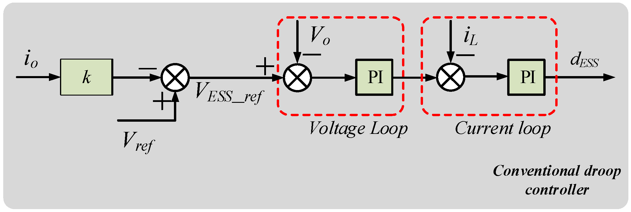
ESSs are important parts of a PV-ESS microgrid system, as they make up the power shortfall when the DGs are unable to meet the load demand. In off-grid operation, the bus voltage loses the support of a larger grid. The energy storage converter usually needs to use droop control to maintain the voltage and power balance of the DC microgrid. The reference voltage of the storage converter, , is expressed as,
where is the nominal voltage of the microgrid, io is the output current, and k is the droop coefficient.
A block diagram of a traditional droop controller is shown in Figure 7. The difference between and the output voltage is sent to the closed voltage–current double control loop to generate the duty cycle dESS for the control of the bidirectional DC/DC converter.
The capacity of the ESS is closely related to the SOC. Using the charging characteristics of lithium-ion batteries, as an example, as shown in Figure 8a, we note that, to maximize the life of the ESS, overcharging and over-discharging should be avoided. Therefore, upper and lower SOC limits are defined for the ESS, termed SOCmax and SOCmin, respectively, in this paper. Based on Figure 8a, charging should be stopped when SOCmax is reached. Similarly, discharging should be stopped at SOCmin. The effect of operating beyond these limits is depicted in Figure 8b, where region A is the over-discharging range (ODR), region B is the overcharging range (OCR), and the intermediate region is the normal operation range (NOR). In regions A and B, there are nonlinear variations in the voltage of the energy storage battery with decrease or increase in the SOC. In contrast, in the NOR region, the relationship between the SOC and the change in the voltage of the energy storage battery is linear [26,27].
In this paper, we adopt an energy storage control scheme that considers SOC. Vmax, Vref, and Vmin, highlighted in Figure 8c, are the maximum, nominal, and minimum values, respectively, of the voltage of the microgrid in the permitted operation state. When the SOC is relatively high, the output voltage is raised correspondingly. Otherwise, when the SOC is relatively low, the reference value for the output voltage is reduced.
During normal grid voltage and SOC operation, the value of the output voltage is increased when the SOC is high. If the ESS is in a charge state, under the control of the proposed scheme, the charging voltage will be smaller than the nominal voltage. Conversely, if the ESS is in a discharge state, the discharge voltage will be larger than the nominal voltage. Thus, by considering SOCref, the ESS will be in a “more discharge and less charge” mode. In contrast, when the SOC is low, the droop controller will decrease its output voltage. If the ESS is in a charging state, the charging voltage will be larger than the nominal voltage, while in the discharge state, the discharge voltage is smaller than the nominal voltage. Hence, by considering SOCref, the ESS will be in a “more charge and less discharge” operation mode.
Unlike the traditional droop control method, the SOC-based droop control strategy maintains the different energy storage units in a “both chargeable and dischargeable” state, as much as possible, by ensuring that the SOC approaches SOCref. Hence, this strategy avoids the microgrid power imbalance phenomenon, caused by the overcharging or over-discharging of the ESS. The SOCref and droop control coefficient mESS of the ESS can be defined as in (9) and (10):
A block diagram of the ESS control strategy is shown in Figure 9, where Vo is the output voltage of the bidirectional DC/DC converter, iL is the current of the inductor in the converter, and is given by
4. Simulation Validation
In this section, we consider simulations of the proposed control strategies, using models built in the MATLAB/Simulink environment (R2016b, Mathworks, Natick, MA, USA). We divide the simulation scenarios into two parts. Section 4.1 discusses the effects of transferring the PV unit controller between MPPT and voltage stabilization using the seamless transfer control strategy avoiding the dead zone. Section 4.2 presents the construction of a PV-ESS DC microgrid model, which includes the transfer strategy discussed in Section 4.1, to verify the effect of the proposed control technology on the transitions between the different modes of PV-ESS DC microgrid operation. Detailed simulation parameters are listed in Table 1, while details of the working conditions simulated are listed in Table 2, Table 3 and Table 4.
4.1. Simulation of PV Controller
To verify the seamless transfer and anti-dead zone control strategy proposed in this paper, we built a model of a PV power generation unit with an independent load without ESS for simulation. The simulation conditions were set as in Table 2. The reference for the voltage stabilizer was 1000 V, and the irradiance intensity was maintained at 1000 W/m2. A P&O algorithm was used for MPPT control, and the simulation time was 1.2 s.
The results of these simulations are summarized in Figure 10. Figure 10a shows the output power, current, and voltage of the PV panels, while Figure 10b shows the load voltage, current, and power. To verify the proposed control strategy, we compare its performance with that of a normal control strategy. The results of the seamless transfer and anti-dead zone control strategy are depicted using the red line in Figure 10, while the blue line illustrates the results of the normal control strategy. Below is a summary of the performance of the two strategies at different stages of operation.
- From 0–0.3 s: At this time, the PV grid is in Mode III and the controller is maintained in an MPPT state. The performance of the proposed transfer strategy is thus identical to that of the conventional method. At this point, the output power is 20 kW.
- From 0.3–0.5 s: At this point, the PV grid is in Mode V. The performance of both strategies is again identical, as under the MPPT control in the previous state. The bus voltage is higher than the reference value (1000 V). Meanwhile, the forward conduction diode in series with the output side of the boost circuit prevents energy reflux. Hence, the switching transistor of the boost circuit is in the off state, and the DC side energy is absorbed by the load until the voltage is restored to 1000 V. The voltage regulator plays a role in maintaining the voltage and power balance of the system.
- From 0.5–1.0 s: At this time, the simulation considers the transition of the PV modules from the voltage regulation to MPPT operation. As no seamless transfer control is included in the conventional method, the bus voltage and power fluctuate, which affects the load and stability of the DC microgrid. In contrast, with the proposed control strategy, there is a seamless transition of the output power from the rated value in the voltage stabilization state, to 20 kW, the value for the MPPT state, with no obvious buffeting during transition. The increased simulation time is to ensure that the transition from Mode VI to Mode IV, and then to Mode III, can be modelled. In order to illustrate the effect of the seamless transfer algorithm, the simulation adopts an independent carrier mode, without energy storage control. With a constant load, the maximum power point is greater than the regulated power. Therefore, under MPPT control, the bus voltage increases.
- From 1.0–1.2 s: At this point, the PV control is switched from MPPT to voltage stabilization, similar to the process that occurs between 0.3 and 0.5 s. However, in this stage, the load is decreased to 35 Ω, and the load power at the reference voltage exceeds the maximum allowable PV power under voltage stabilization control. The PV units are thus unable to maintain the load capacity at 1000 V. Using a voltage stabilization algorithm without anti-dead zone control, in this condition, would inevitably lead to PV failure, as mentioned in Section 2. The working point will slip to the left of the PV U–I curve, the switching transistor of the boost circuit will be in an open state, the PV unit will be in a short-circuit state with zero output power and zero load current, and the system will become unstable. If the proposed anti-dead zone control algorithm is adopted, the system will not slide to the left of the U–P curve, as the initial working point of the PV system will be on the right side of the maximum power point. The output power will be clamped and the output voltage can be reduced without it being equal to the reference voltage. The stability of the microgrid can thus be maintained to a certain extent. This state is consistent with Mode V.
4.2. Simulation of PV-ESS Microgrid
In this section, we verify the operation of the proposed PV control and energy storage control algorithms using simulations. To compare the different ESS control strategies, we built a PV DC microgrid model with two energy storage batteries. The control strategy proposed in this paper was adopted in the first battery (ESS 1), while the conventional control strategy was adopted in ESS 2. The operation of the DC microgrid under different simulation conditions is summarized below.
Simulation condition 1: In this condition, a P&O algorithm was adopted for MPPT control. For the voltage stabilization control strategy, the reference voltage was set to 1000 V. The SOC of ESS 1 and 2 were set to 0.8, which corresponded to SOCmax. At this point, only the discharge of the ESS was permitted. The duration of the simulation was 0.8 s. The different operational modes and working conditions considered in this simulation are summarized in Table 3. The results of this simulation are shown in Figure 11.
The PV microgrid operation in Mode V was simulated from 0–0.2 s. From Figure 11, it can be observed that, when the ESS was fully charged and the load power was less than the maximum power of the PV system, the PV module was able to supply the load independently. At this stage, the PV system was able to stabilize the bus voltage at 1000 V, and the ESS was inactive. The output power was maintained at 8.33 kW, which was less than the maximum power point, which validated the anti-dead zone control method.
Mode VI of PV microgrid operation was simulated from 0.2–0.5 s. Here, the load decreased sharply to 35 Ω while the irradiance was kept constant. As a result, the PV system was not able to maintain the power balance of the microgrid independently, and the ESS had to be involved in the voltage regulation. The control strategy for the PV system was switched from voltage stabilization to MPPT, to achieve the maximum output power of 20 kW. The effects of adopting a droop control strategy focused on SOC protection in ESS 1 can be seen in Figure 11c. We note that, at a high SOC, the discharge rate of ESS 1 is higher than that of ESS 2, which lacks SOC protection.
From 0.5–0.8 s, the load was kept constant, while the irradiance was suddenly reduced from 1000 W/m2 to 700 W/m2. The maximum power point of PV system was decreased accordingly. To maintain the power balance, the ESSs increased their output powers. At this point, the output of ESS 1 increased faster than that of ESS 2, so that overcharging was avoided in the case of a high SOC.
The results of this simulation show that, when the proposed control systems are included in PV-ESS DC microgrids, the PV modules can stabilize the DC bus voltage, and the transfer between the voltage stabilization and MPPT modes of operation is smooth. Moreover, the droop control strategy, which considers the SOC of the energy storage units, can increase the output power of the ESS in a manner wherein overcharging is avoided when the SOC is high, in contrast to the conventional control, where the SOC is not considered. Hence, adopting this SOC-based droop control strategy can be effective in protecting the storage batteries.
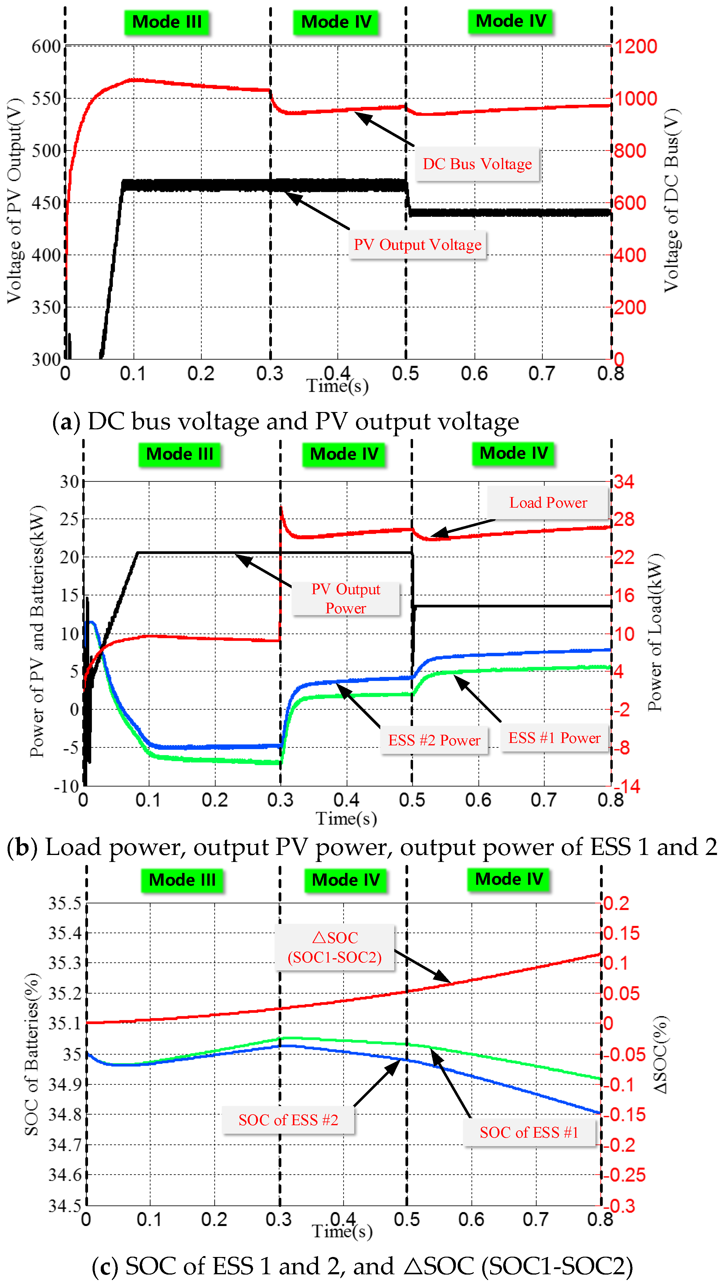
Simulation condition 2: In this condition, a P&O algorithm was adopted for MPPT control and the reference for the voltage stabilization control strategy was 1000 V. The SOC of ESS 1 and 2 were set to 0.35, and the duration of the simulation was 0.8 s. The different operational modes and working conditions considered in this simulation are summarized in Table 4, and the results of the simulation are shown in Figure 12.
The PV microgrid operation in Mode III was simulated from 0–0.3 s. At this stage, while the SOC of the ESSs was below SOCmax, the PV modules supplied the load and were operated in the MPPT mode. The residual PV output was used to charge the ESSs and the SOC of both ESS 1 and 2 increased. The output power at this point was 20 kW. Since an SOC-based droop control strategy was adopted in ESS 1, it had a faster charging rate at a low SOC than ESS 2, which used a conventional control strategy.
Mode IV was simulated from 0.3–0.5 s. At this stage, the irradiance was constant, while the load was reduced to 35 Ω. The PV modules were unable to maintain the load power, and the ESS regulated the DC voltage by discharging. As ESS 1 adopted an SOC-based droop control strategy, at low SOCs, its discharge rate was slower than that of ESS 2, which did not adopt the proposed strategy, to avoid entering an over-discharging state. This slower discharge can be seen by comparing the decrease in SOC using Figure 12c.
The microgrid operation in Mode IV was again simulated from 0.5–0.8 s. However, in this case, the load was kept constant, while the irradiance was reduced from 1000 W/m2 to 700 W/m2. The maximum power of the PV modules was consequently decreased. To maintain the power balance of the microgrid, the output powers of the ESSs were increased. Because of this mandated increase in the output power, the SOC of ESS 2 dropped even faster, as seen in Figure 12c. In contrast, at low SOCs, ESS 1, which adopted the SOC-based droop control strategy, maintained a slower discharge rate, to avoid premature encounter of the lower SOC limit and over-discharging.
The results of this simulation show that an ESS that adopts the SOC-based droop control strategy will be able to maintain a higher charging rate and lower discharge rate, as appropriate, at lower SOCs, than one controlled using a conventional strategy. This SOC-based control is effective in preventing the ESS from reaching the lower SOC limit prematurely, and entering the over-discharge condition, thus protecting the PV-ESS system.
5. Conclusions
In this paper, we analyzed the independent operation of PV energy storage DC microgrids. Six typical operation modes including boundary conditions were defined, from the perspective of power balance of a PV-ESS DC microgrid in off-grid operation. The boundary conditions defined in this paper were functions of the maximum power of the PV modules, the load power at the current DC bus voltage, and the state of the ESS. By combining the characteristics of the PV modules and energy storage units, we analyzed the key control technologies for the transition between the different modes of operation, for designing improved control strategies.
Our analysis revealed that the voltage regulation mode of a PV system in the off-grid operation was prone to failure, because of the closed double controller traditionally used in this mode. By adaptively limiting the amplitude of the current of the inner loop, we established a voltage stabilization process in which the PV modules were operated in the region to the right of the maximum power point only, as defined by the U–P curve of the generation units, preventing the system from entering the dead zone. We also designed a control strategy for the seamless transfer of the PV generation units between MPPT operation and DC bus voltage stabilization. Through simulations, the method was proven to be effective in reducing the output voltage and power fluctuations caused by PV mode switching.
Finally, we compared the performance of a traditional droop control process with that of an SOC-based droop voltage stabilization strategy. Our experiments indicated that the second strategy was able to prevent lifetime damage of the energy storage units, caused by excessive charging and discharging. As this method is simple to implement, it is suitable for use in PV-ESS DC power generation systems.
Constrained by computational capabilities of simulation platform in the laboratory, it is unfortunate that the paper could not include larger time horizon simulation. Moreover, in this study, since the simulations include many switching devices (boost and bidirectional DC-DC converters), in order to improve the simulation accuracy as much as possible, we used a very small simulation step size (5 × 10⁻⁷ s), which required a lot of computational memory. Hence, a simulation time of over several seconds could not be examined by using this type of simulation.
Notwithstanding these limitations, the study suggests that the method is effective in reducing the output voltage and power fluctuations caused by PV mode switching. Further research can be conducted to determine the effectiveness of the proposed method under other types of simulation studies, such as real-time simulations, which can be used to perform longer simulations.
Author Contributions
M.C. designed the research method. M.C. and S.M. wrote a draft of the manuscript. H.W. built the simulation model in MATLAB/Simulink. J.W. and Y.J. provided important guidance. All authors have read and approved the final manuscript.
Funding
This work was financially supported by the National Natural Science Foundation of China (No. 51677002) and the China Postdoctoral Science Foundation (No. 2018M631307).
Conflicts of Interest
The authors declare no conflict of interest.
References
- Bloemink, J.M.; Green, T.C. Benefits of Distribution-Level Power Electronics for Supporting Distributed Generation Growth. IEEE Trans. Power Del. 2013, 28, 911–919. [Google Scholar] [CrossRef]
- Dragicevic, T.; Guerrero, J.M.; Vasquez, J.C.; Skrlec, D. Supervisory control of an adaptive-droop regulated dc microgrid with battery management capability. IEEE Trans. Power Electr. 2014, 29, 695–706. [Google Scholar] [CrossRef]
- Eghtedarpour, N.; Farjah, E. Control strategy for distributed integration of photovoltaic and energy storage systems in dc micro-grids. Renew. Energy 2012, 45, 96–110. [Google Scholar] [CrossRef]
- Sechilariu, M.; Locment, F.; Wang, B. Photovoltaic Electricity for Sustainable Building. Efficiency and Energy Cost Reduction for Isolated DC Microgrid. Energies 2015, 8, 7945–7967. [Google Scholar] [CrossRef] [Green Version]
- Patterson, M.; Macia, N.F.; Kannan, A.M. Hybrid microgrid model based on solar photovoltaic battery fuel cell system for intermittent load applications. IEEE Trans. Energy Convers. 2015, 30, 359–366. [Google Scholar] [CrossRef]
- Lu, X.; Guerrero, J.M.; Sun, K.; Vasquez, J.C.; Teodorescu, R.; Huang, L. Hierarchical Control of Parallel AC-DC Converter Interfaces for Hybrid Microgrids. IEEE Trans. Smart Grid 2014, 5, 683–692. [Google Scholar] [CrossRef]
- Gu, Y.; Li, W.; He, X. Frequency-coordinating virtual impedance for autonomous power management of dc microgrid. IEEE Trans. Power Electr. 2015, 30, 2328–2337. [Google Scholar] [CrossRef]
- Brenna, M.; Dolara, A.; Foiadelli, F.; Lazaroiu, G.C.; Leva, S. Transient Analysis of Large Scale PV Systems with Floating DC Section. Energies 2012, 5, 3736–3752. [Google Scholar] [CrossRef] [Green Version]
- Chen, D.; Xu, L.; Yao, L. DC Voltage Variation Based Autonomous Control of DC Microgrids. IEEE Trans. Power Del. 2013, 28, 637–648. [Google Scholar] [CrossRef]
- Lu, X.; Guerrero, J.M.; Sun, K.; Vasquez, J.C. An improved droop control method for dc microgrids based on low bandwidth communication with dc bus voltage restoration and enhanced current sharing accuracy. IEEE Trans. Power Electr. 2014, 29, 1800–1812. [Google Scholar] [CrossRef]
- Justo, J.J.; Mwasilu, F.; Lee, J.; Jung, J.-W. Ac-microgrids versus dc-microgrids with distributed energy resources: A review. Renew. Sustain. Energy Rev. 2013, 24, 387–405. [Google Scholar] [CrossRef]
- Lee, S.W.; Cho, B.H. Master–Slave Based Hierarchical Control for a Small Power DC-Distributed Microgrid System with a Storage Device. Energies 2016, 9, 880. [Google Scholar] [CrossRef]
- Wang, P.; Lu, X.; Yang, X.; Wang, W.; Xu, D. An improved distributed secondary control method for dc microgrids with enhanced dynamic current sharing performance. IEEE Trans. Power Electr. 2016, 31, 6658–6673. [Google Scholar] [CrossRef]
- Augustine, S.; Mishra, M.K.; Lakshminarasamma, N. Adaptive droop control strategy for load sharing and circulating current minimization in low-voltage standalone dc microgrid. IEEE Trans. Sustain. Energy 2015, 6, 132–141. [Google Scholar] [CrossRef]
- Zeng, Z.; Yang, H.; Zhao, R.; Meng, J. Nonlinear characteristics of observed solar radiation data. Sol. Energy 2013, 87, 204–218. [Google Scholar] [CrossRef]
- Ahmed, J.; Salam, Z. An improved perturb and observe (p&o) maximum power point tracking (mppt) algorithm for higher efficiency. Appl. Energy 2015, 150, 97–108. [Google Scholar] [CrossRef]
- Mamarelis, E.; Petrone, G.; Spagnuolo, G. A two-steps algorithm improving the p&o steady state mppt efficiency. Appl. Energy 2014, 113, 414–421. [Google Scholar] [CrossRef]
- Ma, S.; Chen, M.; Wu, J.; Huo, W.; Huang, L. Augmented nonlinear controller for maximum power-point tracking with artificial neural network in grid-connected photovoltaic systems. Energies 2016, 9, 1005. [Google Scholar] [CrossRef]
- Dolara, A.; Grimaccia, F.; Mussetta, M.; Ogliari, E.; Leva, S. An Evolutionary-Based MPPT Algorithm for Photovoltaic Systems under Dynamic Partial Shading. Appl. Sci. 2018, 8, 558. [Google Scholar] [CrossRef]
- Chen, M.; Ma, S.; Wu, J.; Huang, L. Analysis of mppt failure and development of an augmented nonlinear controller for mppt of photovoltaic systems under partial shading conditions. Appl. Sci. 2017, 7, 95. [Google Scholar] [CrossRef]
- Makrygiorgou, D.I.; Alexandridis, A.T. Stability Analysis of DC Distribution Systems with Droop-Based Charge Sharing on Energy Storage Devices. Energies 2017, 10, 433. [Google Scholar] [CrossRef]
- Lin, P.; Wang, P.; Xiao, J.; Wang, J.; Jin, C.; Tang, Y. An Integral Droop for Transient Power Allocation and Output Impedance Shaping of Hybrid Energy Storage System in DC Microgrid. IEEE Trans. Power Electr. 2017, 33, 6262–6277. [Google Scholar] [CrossRef]
- Yang, H.; Qiu, Y.; Li, Q.; Chen, W. A self-convergence droop control of no communication based on double-quadrant state of charge in DC microgrid applications. J. Renew. Sustain. Energy 2017, 9, 798–801. [Google Scholar] [CrossRef]
- Lu, X.; Sun, K.; Guerrero, J.M.; Vasquez, J.C.; Huang, L. Double-quadrant state-of-charge-based droop control method for distributed energy storage systems in autonomous dc microgrids. IEEE Trans. Smart Grid 2015, 6, 147–157. [Google Scholar] [CrossRef]
- Peng, Y.; Vrancic, D.; Hanus, R. Anti-windup, bumpless, and conditioned transfer techniques for pid controllers. IEEE Control. Syst. Mag. 1996, 16, 48–57. [Google Scholar] [CrossRef]
- Zhang, C.; Wang, L.Y.; Li, X.; Chen, W.; Yin, G.G.; Jiang, J.C. Robust and Adaptive Estimation of State of Charge for Lithium-Ion Batteries. IEEE Trans. Ind. Electron. 2015, 62, 4948–4957. [Google Scholar] [CrossRef]
- Ahmed, R.; El Sayed, M.; Arasaratnam, I.; Tjong, J.; Habibi, S. Reduced-order electrochemical model parameters identification and soc estimation for healthy and aged li-ion batteries part I: Parameterization model development for healthy batteries. IEEE J. Emerg. Top. Power Electron. 2014, 2, 659–677. [Google Scholar] [CrossRef]
Figure 1.
Diagram of a PV-ESS DC microgrid system.

Figure 2.
Structure of a DC microgrid in off-grid operation.

Figure 3.
Operation modes of an off-grid DC microgrid.
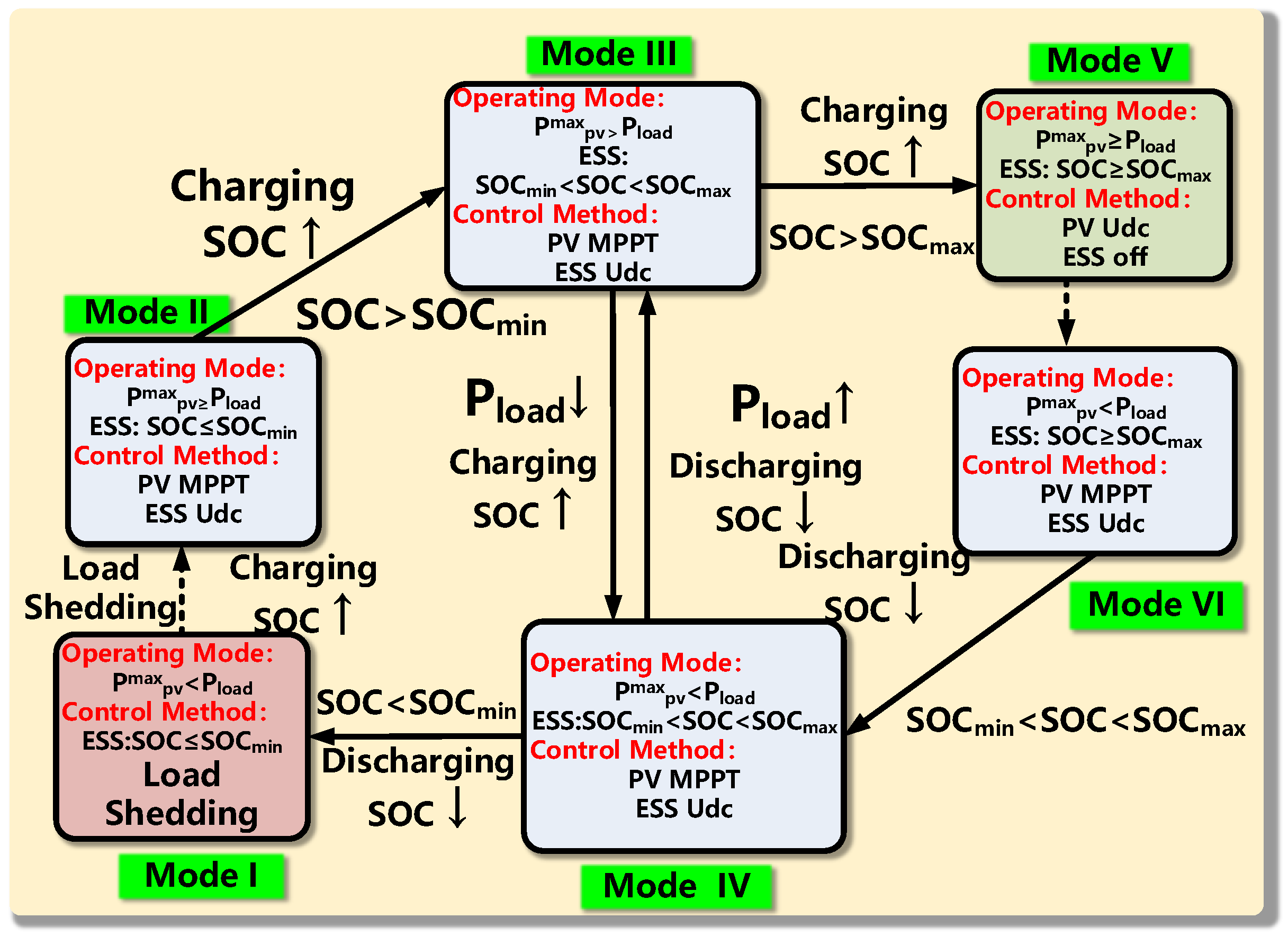
Figure 4.
Illustration of working points of a PV power generation system. The inset depicts a circuit diagram of the system and a block diagram of the controller.
Figure 4.
Illustration of working points of a PV power generation system. The inset depicts a circuit diagram of the system and a block diagram of the controller.

Figure 5.
Stable PV module operating regions for constant voltage control, at different irradiances.
Figure 5.
Stable PV module operating regions for constant voltage control, at different irradiances.
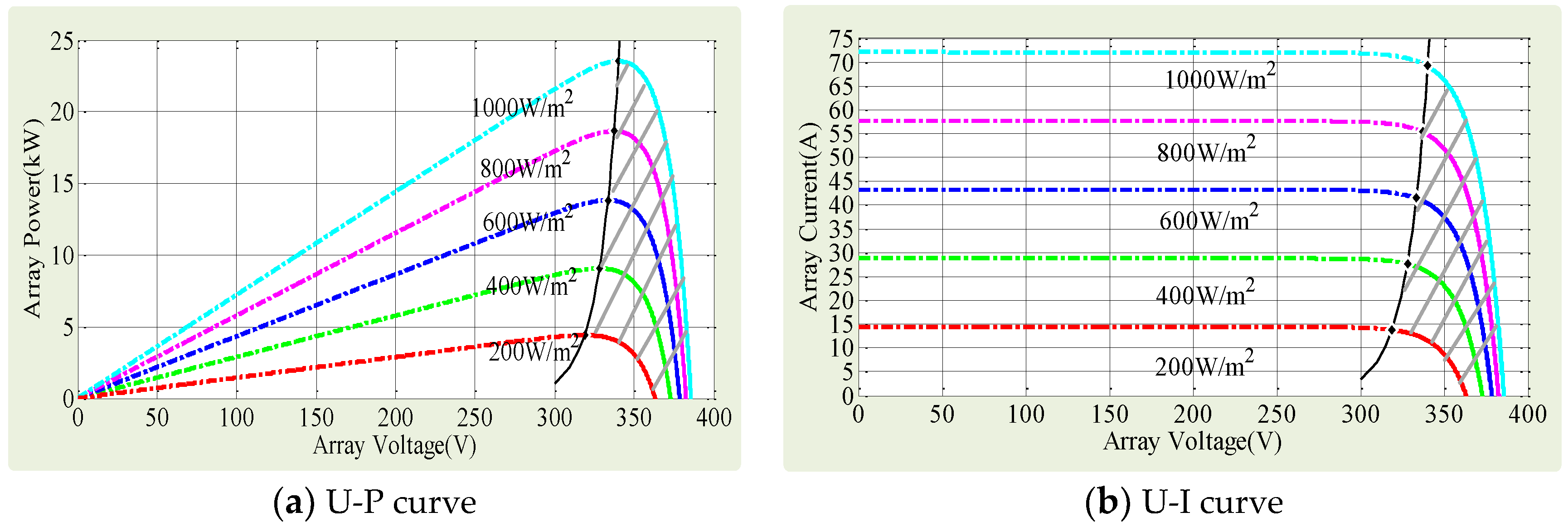
Figure 6.
Controller for seamless transfer between voltage stabilization and MPPT operation of a PV generation unit.
Figure 6.
Controller for seamless transfer between voltage stabilization and MPPT operation of a PV generation unit.

Figure 7.
Block diagram of a traditional droop controller.

Figure 8.
Conditions for stable ESS control. (a) Operating regions; (b) Characteristic curve of a lithium-ion battery with respect to SOC; (c) Schematic diagram for designing an SOC-based droop control strategy.
Figure 8.
Conditions for stable ESS control. (a) Operating regions; (b) Characteristic curve of a lithium-ion battery with respect to SOC; (c) Schematic diagram for designing an SOC-based droop control strategy.
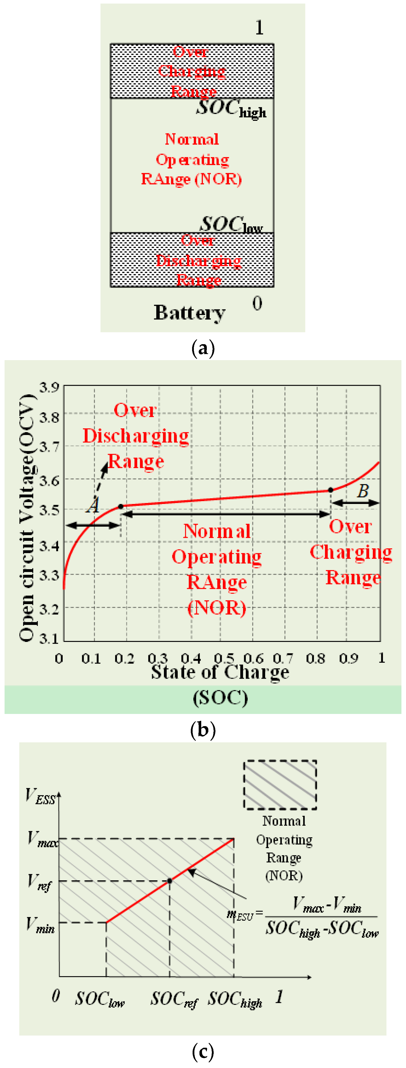
Figure 9.
SOC-based energy storage droop controller.
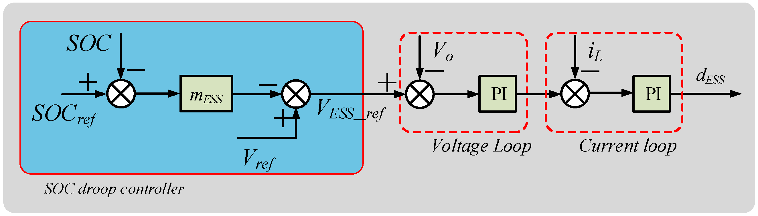
Figure 10.
Results of seamless transfer and anti-dead zone control simulation.
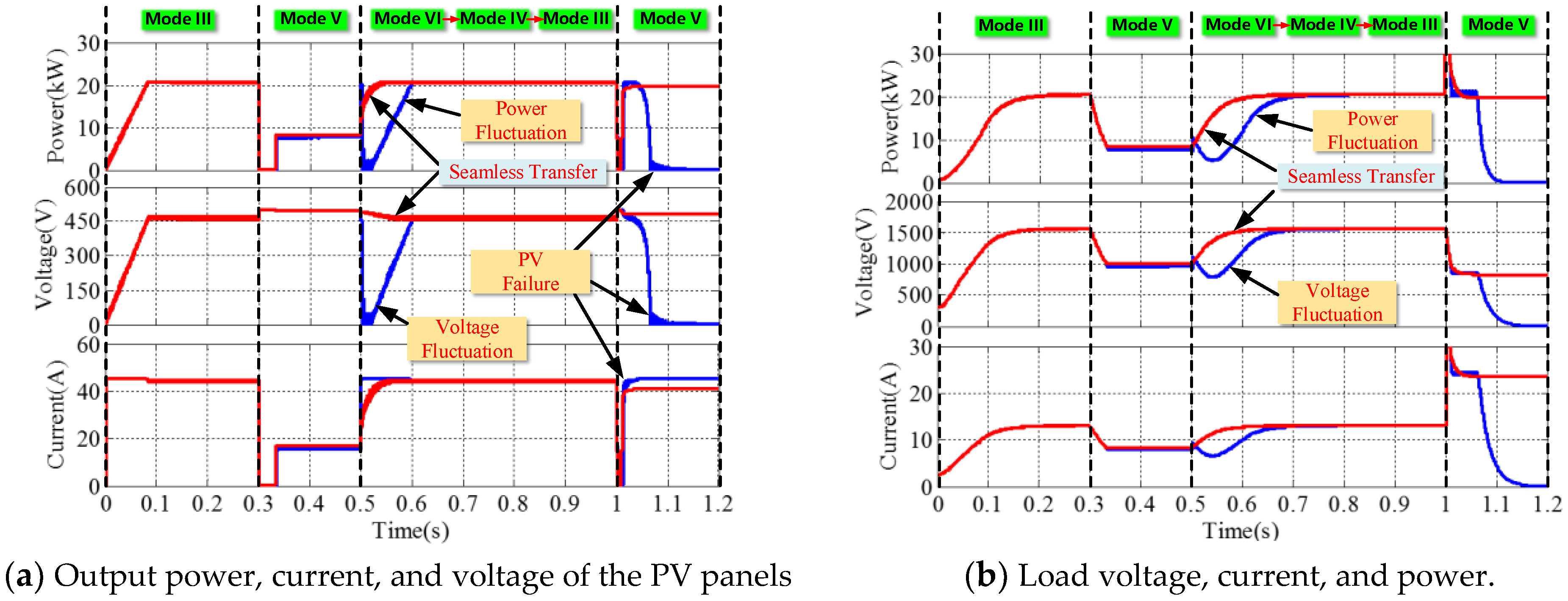
Figure 11.
Results of PV-ESS DC microgrid simulation for condition 1.
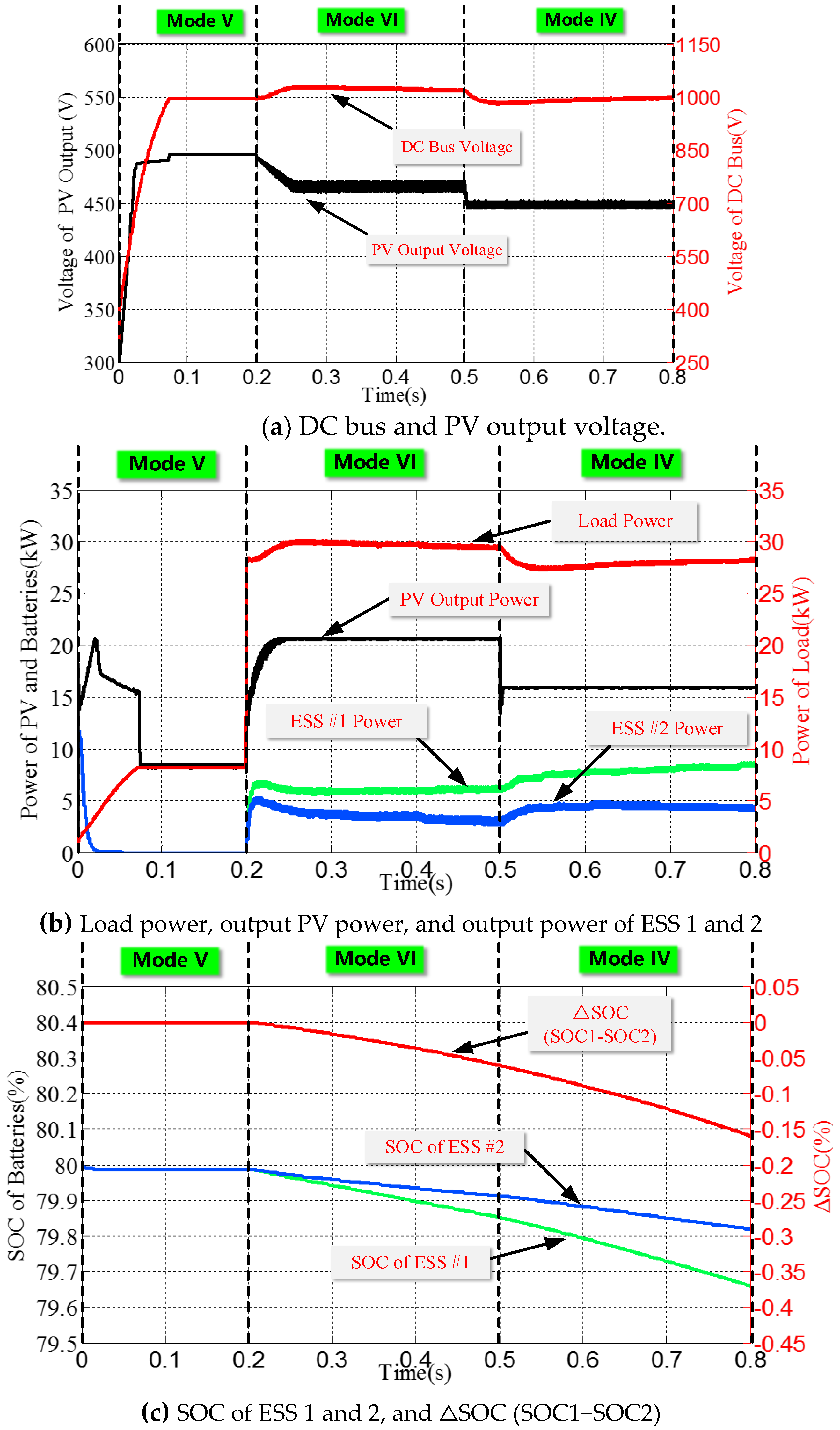
Figure 12.
Results of PV-ESS DC microgrid simulation for condition 2.

Table 1.
Parameters of the PV modules and ESS used in simulation.
| Parameter | Value | |
|---|---|---|
| PV | Vocn (PV open-circuit voltage) | 500 V |
| Iscn (PV short-circuit current) | 48 A | |
| VMPP (MPP voltage) | 465 V | |
| IMPP (MPP current) | 45 A | |
| VMPP (MPP power) | 20.9 kW | |
| PV input capacitance | 330 μF | |
| PV output capacitance | 730 μF | |
| PV inductance | 3 mH | |
| ESS | Battery input capacitance | 330 μF |
| Battery output capacitor | 630 μF | |
| Battery inductor | 1 mH | |
| SOCmax | 0.8 | |
| SOCmin | 0.2 | |
| Control parameter | Kp (PV boost convert) Ki (PV boost convert) | 0.31 12.2 |
| Kp (Bi-DC-DC convert) Ki (Bi-DC-DC convert) | 5.72 0.325 | |
| Ka | 0.001 |
Table 2.
Simulated PV working conditions.
| Incident | Time (s) | Mode | PV Control Strategy and Load Resistance |
|---|---|---|---|
| 1 | 0–0.3 | III | MPPT, Rl = 120 Ω |
| 2 | 0.3–0.5 | V | MPPT−Udc, Rl = 120 Ω |
| 3 | 0.5–1.0 | VI→IV→III | Udc−MPPT, Rl = 120 Ω |
| 4 | 1.0–1.2 | V | MPPT−Udc, Rl = 35 Ω |
Table 3.
Description of simulated working condition 1.
| Incident | Time (s) | Mode | Working Condition |
|---|---|---|---|
| 1 | 0–0.2 | V | S = 1 kW/m2, Rl = 120 Ω |
| 2 | 0.2–0.5 | VI | S = 1 kW/m2, Rl = 35 Ω |
| 3 | 0.5–0.8 | IV | S = 0.7 kW/m2, Rl = 35 Ω |
Table 4.
Description of simulated working condition 2.
| Incident | Time (s) | Mode | Working Condition |
|---|---|---|---|
| 1 | 0–0.3 | III | S = 1 kW/m2, Rl = 120 Ω |
| 2 | 0.3–0.5 | IV | S = 1 kW/m2, Rl = 35 Ω |
| 3 | 0.5–0.8 | IV | S = 0.7 kW/m2, Rl = 35 Ω |
© 2018 by the authors. Licensee MDPI, Basel, Switzerland. This article is an open access article distributed under the terms and conditions of the Creative Commons Attribution (CC BY) license (http://creativecommons.org/licenses/by/4.0/).
Share and Cite
MDPI and ACS Style
Chen, M.; Ma, S.; Wan, H.; Wu, J.; Jiang, Y. Distributed Control Strategy for DC Microgrids of Photovoltaic Energy Storage Systems in Off-Grid Operation. Energies 2018, 11, 2637. https://doi.org/10.3390/en11102637
AMA Style
Chen M, Ma S, Wan H, Wu J, Jiang Y. Distributed Control Strategy for DC Microgrids of Photovoltaic Energy Storage Systems in Off-Grid Operation. Energies. 2018; 11(10):2637. https://doi.org/10.3390/en11102637
Chicago/Turabian StyleChen, Mingxuan, Suliang Ma, Haiyong Wan, Jianwen Wu, and Yuan Jiang. 2018. "Distributed Control Strategy for DC Microgrids of Photovoltaic Energy Storage Systems in Off-Grid Operation" Energies 11, no. 10: 2637. https://doi.org/10.3390/en11102637
Note that from the first issue of 2016, this journal uses article numbers instead of page numbers. See further details here.