PV System Design and Flight Efficiency Considerations for Fixed-Wing Radio-Controlled Aircraft—A Case Study


1
Faculty of Engineering, University of Rijeka, Vukovarska 58, 51000 Rijeka, Croatia
2
Institute of Control, Robotics and Information Engineering, University of Technology, Piotrowo 3a, 60-965 Poznań, Poland
*
Author to whom correspondence should be addressed.
Energies 2018, 11(10), 2648; https://doi.org/10.3390/en11102648
Submission received: 28 August 2018
/
Revised: 29 September 2018
/
Accepted: 1 October 2018
/
Published: 3 October 2018
(This article belongs to the Special Issue Solar and Wind Energy Forecasting)
Abstract
:The list of photovoltaic (PV) applications grows longer every day with high consideration for system efficiency. For instance, in spite of many recent PV aircraft designs, aircraft propulsion was mainly reserved for nonelectric motors. Lately, the Solar Impulse flight across the world shows the possibilities of larger PV powered electric aircraft. In order to obtain this goal efficiency of flight, PV conversion, power converters and electric drives have to be maximized. These demands led to a 63.4 m wingspan. The purpose of this paper is to present that PV power could be used for improving the performance of fixed-wing radio-controlled aircrafts with smaller wingspans (1 m). In order to improve the performance of battery powered electric unmanned aerial vehicles (UAV), a model without PV cells (commercial Li-ion battery powered UAV) was compared with UAV powered both from battery and PV modules. This work shows details about Boost DC/DC converter and PV system design for small size fixed-wing electric UAVs, investigating the possibility of the application of PV powered drones, as well. Theoretical findings involving efficiency improvements have been confirmed by measurements combining the improvements in electrical engineering, microcontroller application and aerodynamics.
1. Introduction
1.1. PV Systems for Unmanned Electric Aircrafts
Photovoltaic technology has been developing for decades but in last twenty years, investments have been additionally increased [1]. The number of applications of PV modules is growing and solar cells have been used in applications that were not common several years ago [2]. For instance, solar cars are used widely for transportation in common life [3]. For traveling across large distances, PV powered airplanes are used [4,5,6]. At the beginning of the 21st century, solar cells were generally proposed for stationary applications, mostly on flat roofs [7]. Examples of such an approach are documented in the literature, where photovoltaic sources along with LED lighting are used for street lights and other urban applications [8,9]. It seems that global energetics will be governed by photovoltaic sources for all applications where its use is possible (including mobile devices, drones and similar). In comparison, fossil fuels could aid in developing pollution problems in large cities (e.g., Beijing); therefore, restrictions on fossil fuel consumption are possible. Nuclear energy is also avoided because of problems with nuclear waste and because of fear of potential accidents, such as the nuclear power plant accident that occurred at Daiichi Fukushima in 2011 [10]. Transport is also an important issue from an energetic point of view. For example, conventional airplanes consume large quantities of kerosene, so there are efforts to reduce that consumption in order to achieve both economic and ecological impact on modern life [11].
In this paper, an improvement of radio-controlled aircraft with a PV system addition has been investigated. The Solar Impulse project has shown that PV powered airplanes can fly across great distances [5,12,13], but what about smaller planes at lower altitudes? Is it possible for them to stay in the air for a few days? In this paper, a radio-controlled unmanned aerial vehicle (UAV) with a fixed-wingspan of less than 1 m has been tested without a PV supply. Different flight data like flight speed, range and time have been measured. Mass increase of the UAV (PV modules are no exception) results in shorter flight time. On the other hand, additional PV energy could compensate for battery discharging and increase flight time. Compared to the same problem in road vehicles, airplanes and their models are more exposed to periodic wind blows, sun radiation fluctuation and nonlinear phenomena of thermal air flows. In the literature, different approaches could be found, including the axiomatic approach [14] or more conventional approaches [15,16,17,18,19,20]. After the calculations, an additional PV source has been added to the wings including a Boost DC/DC power converter with a maximum power tracking (MPPT) function [21,22]. Special care has been added to the DC/DC power converter in order to reduce its mass, so different approaches were tested and compared. Finally, a new fixed-wing radio-controlled UAV based on [23] was designed at this time with a flying stability problem. After solving the stability problem, a new model (the old model with an added PV system) was obtained with improved flying capabilities. This approach is different from the classic design available in recent literature due to a change in the existing design, since the addition of a power source influences aerodynamics and the efficiency of flight in different ways [24,25]. In this paper results are obtained by changing the limited number of parameters of fixed-wing UAV as in a recent publication [26].
Concerning the solar radiation in kW/m2, different data obtained for different areas of the world could be found in the literature. Solar radiation measured in the United Kingdom (UK) is quite low, with maximum values of daily solar radiation below 1 kW/m2 [27,28,29]; furthermore, frequent cloud appearance results in intervals with solar radiation below 500 W/m2. On the other hand, in India and Australia, a solar radiation of 135 kW/m2 is used frequently in calculations. In that context, it is interesting to mention research provided for Europe in comparison to other parts of world [30,31]. Solar radiation in Europe generally has lower values than in Australia, however occasionally could obtain values up to 1.1 kW/m2, which is measured in Alpine [30] or Mediterranean regions [31]. Geographically, Croatia is situated on the Mediterranean with a hilly central and southern part and the Pannonia plane on the northern border with Hungary. In the Rijeka region, values up to 1.1 kW/m2 could be measured. Data available from the European Commission states that solar radiation is lower (up to 1000 W/m2 for coastal cities on the Adriatic sea) [32], however in recent years, values higher than 1 kW/m2 could be measured [33], and the solar potential of the northern Adriatic seems to be higher compared to UK [29] or Japanese cities [10] and could be compared on public databases [34].
In this paper, a value of solar radiation of 1.1 W/m2 was estimated from weather forecast databases, similar to other research papers [10,29,33]. Compared to other Mediterranean cities at the same geographical altitude (i.e., Genova, Marseille), Rijeka has lower insolation and can be compared with Portland in the United States (also on the 45° parallel of geographical latitude), but it has a more intense insolation compared to Vladivostok in Russia or Gifu in Japan (which are both more southern than Rijeka, with 43.11° and 35.4° of latitude, respectively). Analysis provided in [10] investigates larger regions discovering the maximal solar radiation which could be expected in targeted area [35] with an approach that includes the estimation of solar radiation for locations 100 km from the city of Gifu. Such data could be used for the prediction of electrical energy generation from photovoltaic sources [31,36]. Experiments concluded in this paper were taken during sunny days in spring and summer; however, with the lower solar radiation experiments, experiments had to be aborted before the planed (15 min) interval, because the UAV battery could not supply energy for the additional weight without the photovoltaic source.
1.2. State of the Art and History Perspectives
Radio-controlled models have been present for more than 100 years. The first use of radio-controlled electrically powered unmanned aerial vehicles (UAVs) came from Great Britain, and it took place in 1917 [15]. However, this system was not developed further and electrical machines were generally abandoned for UAV applications for a long time. Lately, UAVs were powered with gasoline engines.
An important year for battery powered UAVs and for their electrical propulsion is 1957. In the summer of that year, H. J. Taplin from the United Kingdom made the first recorded radio-controlled flight with the UAV named “Radio Queen”. This vehicle used a permanent magnet DC machine powered with a silver-zinc battery. In spite of the fact that this approach was innovative in avoiding the electrical excitation of the DC machine, as well lead acid batteries, this experiment was not carried on. Further development of electrical powered UAVs was made by Fred Militky from Germany and other researchers. Militky made the first successful radio-controlled flight later that same year. Modern development of electric powered UAVs started in 1957 after the work of Taplin and Militky [17]. It is interesting that the development of electric powered UAVs coincides with the start of development of modern photovoltaic cells.
Even before pioneering radio-controlled flights, a modern solar cell appeared in 1954, made in Bell Telephone Laboratories. In a few years, the efficiency of solar cells improved from 4% to 11%. During the early stages of electric propulsion, research included the discovery of the photovoltaic effect. However, solar cells were not used for a long time (until the seventies of the last century in the case of PV powered UAVs).
The first modern application of a photovoltaic system in electrically propelled UAVs was designed by R. J. Boucher. His 450-watt UAV named Sunrise I flew for twenty minutes for the first time in November 1974. It had a wingspan of almost 10 m and weight of 12.25 kg. In spite of the fact that this UAV had been destroyed in storm, a new improved UAV was designed, reaching 600 W with decreased mass down to 10.21 kg. Again, successful flights were done with Sunrise II before it was destroyed because of failure of the radio-control system [14]. Approximately at the same time, Fred Militky with his PV powered UAV Solaris made a successful flight in the summer of 1976. After that, numerous UAVs were designed. Dave Back set a world record for PV UAVs in 1996 for a distance of 38.84 km. In 1998, he reached an altitude of 1283 m. After him, Wolfgang Schaeper set the world records for the longest duration of UAV flight (11 h, 34 min, 18 sec), UAV flight distance in a straight line (48.31 km) and for altitude (2065 m). After that, the target became continuous manned flight, which was accomplished with Solar Impulse in 2010 [5,14,20]. Today, UAVs are widely available with applications in telecommunications, agriculture, meteorology, border control, ocean observation and military applications [6,37]. At this point, it is hard not to mention the Aquila project [38] solar powered UAV, which has a wingspan as big as a Boeing 737 and can stay in the air for the months. Compared to the Aquila project, the contribution of this paper is to investigate the possibility of obtaining such results for smaller UAVs.
1.3. Theoretical Examination
Conventional airplanes have huge lifting force due to large wing surfaces. PV modules can be mounted on such airplanes, so that they can stay in the air for more hours/days [15]; such is the case for Solar Impulse [5]. On the other hand, drones (UAVs) which do not have a fixed wingspan consume large quantities of electrical power and therefore their time in the air is limited in correlation with battery capacity. Observed aircraft have wings, but their size is not enough to hold a plane in the air for longer periods of time. However, it is expected that flight time would be prolonged in spite of the increased mass of the installed PV system (Figure 1).
In this paper, electric power P is obtained from two sources: (1) battery source and (2) photovoltaic module or photovoltaic cells. Recently, this has been documented in work of Noth et. al. [15,17,19] and other sources [14,20]. Larger drag force Fdrag, and higher cruising speed vf demand larger power consumption P:
Energy supplied from the battery has to cover this (mechanical) power increase with losses (Ploss) of the power converter and brushless machine drive. However, solar cells should cover at least part of this energy in order to increase the flight time. In the case where solar cells could cover all energy given by the battery, continuous flight could be obtained.
Drag force Fdrag depends on velocity vf, also:
Except flight velocity, drag force depends on air density ρ, drag coefficient cdrag and on wing planform A.
This means that minimal flying velocity is proportional to the aircraft weight (mg):
By combining Equations (1), (2) and (4), we can obtain the mechanical power needed for constant cruising speed:
This formula may be used for the comparison of different cases, e.g. insertion of a heavier battery or addition of solar cells. It can be calculated that a mass increase of 10% means a 15% increase in power (consumption) for the same speed, a 40% mass increase means a 65% larger consumption and so on (Figure 2). In the case of solar cells, mass increase also means increase in available power.
In this paper, a fixed-wing radio-controlled aircraft was tested. The mass of the commercial aircraft with a Li-ion battery is 774 g; adding an additional PV module adds an additional 300 g. However, this mass was reduced by removing the plastic cover from the PV module which is partially compensated for by adding a power converter with a microcontroller.
According to Figure 2, flight duration could be extended if the PV system mass (PV module and additional converter) could be compensated for with its own energy. Power P1 represents power from the battery for commercial aircraft, power P2 represents the energy needed for propelling an aircraft with additional mass (the added PV system) and power P3 represents modified aircraft with additional mass and an additional power (PV) source, which is compensating for the additional mass and with reduced consumption from the battery. So, only the P1 > P3 longer flight duration could be accomplished because of consumption decrease. Thus, energy surplus compensates for the battery current, making the battery discharge last longer. At the same time, battery lifetime prolongation could be expected as well. However, if there is a lack of sunlight, generated PV power equals zero and only an additional mass remains, resulting in a shortened flight duration. Commercial fixed-wing radio-controlled aircraft could fly with a consumption of 20 W [23] with its own mass of 774 g, which gives a power density of 0.0258 W/g. On the other hand, PV systems have better power density (PPVMAX = 20 Wp per 300 g, or 0.067 W/g). However, it is more appropriate to take into account converter losses, and to assume that PPV = PPV − Ploss = 15 W.
For the first case (commercial aircraft): ;
For the second case (commercial aircraft with an added PV system): ;
The difference: represents the power increase from the PV system.
The PV system makes approximately 10% of aircraft power consumption during steady cruising. So, theoretically, a 10% improvement in flight duration could be expected if the aerodynamics of the aircraft stays unchanged after the PV system addition. However, the aerodynamic differences and PV production during real flight is hard to model, so a practical test is the only way to validate these theoretical results.
2. Materials and Methods
2.1. Boost DC/DC Power Converter Design
A DC/DC power converter has been designed in order to obtain the minimal mass of the converter in frame of radio-controlled aircrafts with a PV system. The transistor driving circuit, battery voltage, DC link voltage and brushless propulsion engine were chosen to operate at 16 V. Open circuit PV voltage is chosen to be higher (≈20 V) in order to obtain maximum power point tracking (MPPT) at 16 V. In such desirable conditions, the DC power converter is not needed. However, when the insolation drops the photovoltaic voltage (VPV) from 20 V to 10 V or even to 5 V, the input voltage VPV has to be stepped-up in order to charge the battery to the desired voltage (Figure 3). Classic approaches to MPPT functions have disadvantages, especially in conditions of variable solar radiation [29] where frequent cloud appearance could cause loss of photovoltaic power and initiate intensive discharging of the battery. In order to overcome such problems, fuzzy logic controllers have been used frequently [39,40,41].
In spite of the fact that more complex MPPT algorithms could be used [18,19], a simple algorithm with a test solar cell has been applied. This means that sensor solar cell output voltage has been used in order to determine the Boost converter duty cycle. The PV system has been designed in such a way that under optimal conditions (large insolation), the DC/DC power converter is not needed. That means that maximal power has been achieved at battery voltage (16 V). However, under the conditions of decreased insolation or aircraft maneuvering, the DC/DC converter improves partial compensation of battery charge consumption. This has been achieved with variable duty cycle D of transistor T1. When the sensor voltage (VCONTROL in Figure 3) drops from 15% of peak voltage, the transistor operates with low duty cycle (D ≈ 0.1). At lower sensor voltage, the duty cycle increases in order to track the maximum power of the PV module (e.g. D ≈ 0.6 for 25% of peak sensor value). In the case that VPV < 16 V, the PV source will not charge the battery at all, so PV voltage has to be increased according to Boost converter equation:
It is possible to program different values of duty cycle D, so at low voltages (e.g., VPV < 5 V), it is more efficient to turn off the converter than to generate losses via transistor switching. System in Figure 3 is using information from PV sensor (VCONTROL) and elements of fuzzy logic [18,39,41].
In spite of the fact that the PV system is quite simple, three different approaches were tested. In the first solution, a commercial PWM (pulse width modulation) generator (UC3854) from Texas Instruments was used; however, in this case, additional passive components were needed. After that, the “ARM cortex M4” processor in frame of STM32F407 microcontroller (ST company microcontroller) was tested. In this case, a 100-pin microcontroller arose as an obstacle for this application. Finally, an Atmel ATmega328/P low power CMOS (Complementary Metal Oxide Semiconductor) technology 8-bit AVR (family of microcontrollers developed by Atmel company) microcontroller from the “Arduino” microprocessor system was taken, enabling the lowest mass and programming flexibility.
2.2. Fixed-Wing Radio-Controlled Aircraft Model Design and its Modifications
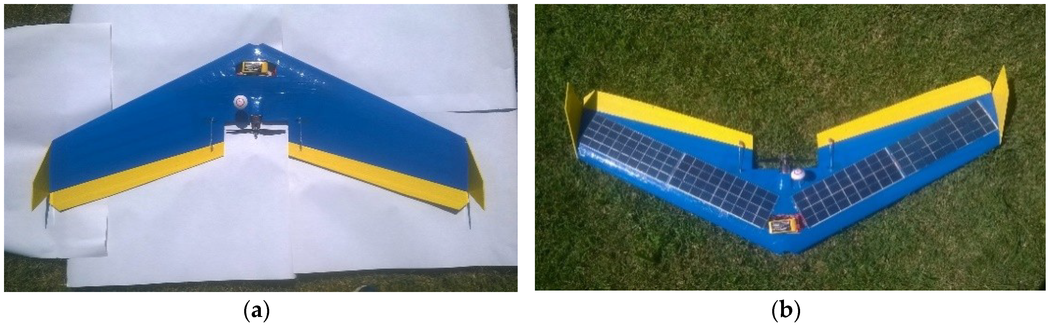
UAV battery current and voltage were measured in real time and data was taken at the same time available on the ground. During the modification of the commercial model aircraft [23], flexible PV modules were used (Figure 4). In order to reduce their mass, a plastic cover from the PV module was removed. Also, the solar module was redesigned from its standard housing for compatibility with wing configuration in order to achieve new connections suitable for the power converter supply.
UAVs are exposed to frequent vibrations during landing and in the air, so there is the possibility of mechanical failure on the UAV. It is the author’s opinion that modern fault diagnosis via thermal imaging or electrical measurements could be used in order to avoid take-off of faulty UAVs [42]. However, it is expected that flexible solar modules have high reliability and certain resistibility on impact [28].
3. Results and Discussion
3.1. Uniform Flight Tests
In order to decrease the influence of rapid wind changes, tests were conducted during sunny (summer) weather (presented measurements were taken on 21–22 July 2016 at summer solstice, so the 1100 W/m2 of solar radiation was taken into account) at Grobnik airport (elevation above sea level 300 m), near Rijeka, Croatia [30,31,33]. Furthermore, the intention was to sustain constant speed and latitude and to test the flight range and flight time for the standard airplane model [23]. At this point, it is useful to support previous calculations. It was taken that PV panels could generate 15 W. This statement could be sustained by the calculation involving solar radiation of 1100 W/m2, solar cell efficiency η of 23% and dimensions of solar panel of 0.2 m·0.3 m (S = 0.06 m2). By multiplying these values [28], an electrical power of 15 W could be obtained:
This calculation shows that flight prolongation is difficult to obtain in conditions of lower solar radiation. However, measurements were taken during sunny days in spring and summer, so the same results for UAV cruising were always obtained. In the case of using solar radiation from [32], the positive effect from the PV module: vanishes:
In that case, power obtained from PV panels minus the power consumption increase according to (5) equals: resulting in a negative effect of PV module insertion into the wings.
During the test, rapid maneuvering could increase battery current and consumption (from 2 A or 3 A to 40 A), so fast maneuvering was avoided, and minimal consumption was a target during the complete test (Table 1). Tests were repeated three times at the aforementioned locations and results coincide with measurements taken earlier at other locations (e.g., Viškovo, near Rijeka, Croatia—also 300 m above sea level).
Data were recorded for the airplane model [23] produced by a Slovenian manufacturer. In frame of the same model, different batteries could be chosen. For this test, a lighter 1300 mAh battery was used. The airplane model without batteries weighs 630 g and 774 g with a battery. After the addition of the PV system, the test was repeated (Table 2).
This time, data was recorded for the modified airplane model. Again, a lighter 1300 mAh battery was chosen. The UAV without batteries weighed 923 g and 1067 g with a battery. This means that the PV system adds 293 g. However, it seemed that consumed charge for the 15 min flight decreased. This is because the PV cells generate enough energy to compensate for the additional mass and more to reduce total consumption. Before the second test flight, the solar module had an open circuit voltage VOC = 20.8 V and short circuit current ISC = 0.96 A. These measurements seem to be enough to calculate the demanded effect produced by an additional PV system. Charge consumption in the first flight was 976 mAh, which is equal to 65 mAh/min or 84 mAh/min/kg.
In this paper, attention was not given to the PV module temperature since tests last only for 15 min and the PV module is cooling during flight, but for future work, the ability of UAVs to withstand flight at high temperatures should also be analyzed [44,45].
During the first test, it was noted that cruising could be obtained with approximately 20 W of electric power. This means that the PV system could cover almost half of that. However, by adding the solar cells, the aircraft mass was increased and the airplane model aerodynamics were changed, so only the practical test could answer the question of whether the PV system could improve the flight performance of the tested aircraft (Figure 5). Charge consumption after the 15 min second flight was lower (915 mAh) compared to the first flight (976 mAh), giving a decrease of 6.25%.
3.2. Discussion
It has been found that during the first few minutes, when the UAV is slowly rising, consumption is almost the same for both UAVs. However, after that (during uniform cruising), when the solar module is in an optimal position concerning sun rays, it appears that solar cells could generate enough energy to compensate for their own mass and to contribute part of energy needed for UAV cruising (Table 3).
The system was designed so the battery current could be measured. This means that the PV system current could be measured only on the ground, or it could be calculated. On the other hand, it could be noticed that the total charge consumption is higher than could be expected from the current measurement. In this way, it is possible to land an airplane model soon enough without the risk of losing power in the air and to avoid deep discharging to prolong the battery life. In these circumstances, it is most appropriate to combine the results from both tests, which means that the charge consumption from the battery is reduced by 6% in spite of a mass increase. This means that more efficient flight can be achieved, which could compensate for the additional expenses of a cost effective PV module. However, this could be obtained only for cruising rather than for acrobatic flight. It could be calculated that the plane without a PV system and with a mass of 1067 g would have average current consumption of ≈3 A, and it could hardly remain in the air during the 15 min flight with a 1300 mAh battery involving an 80–40% charging discharging ratio used for Li-ion batteries. However, for more aggressive flight when the brushless DC machine consumes around 40 A, 1 A or less from the PV system has no positive influence on flight duration since the additional mass has larger negative effect during battery charge consumption. A similar effect occurs from decreased solar radiation (<1000 W/m2). Demonstration of PV system operation could be observed when the UAV instability in the air caused swinging from right to left of the UAV, leaving the UAV’s PV system in shadow for the most of the time. The consequence of this was an instant increase in battery current (from 2 A to 4.5 A). Such flight could get additional information on MPPT and PV system operation in general, however authors decided to land the UAV because of its possible fall.
4. Conclusions
In this paper, the possibility of installing a PV system on a commercial UAV (unmanned aerial vehicle) has been investigated theoretically and practically. Avionic PV applications involve a more complex approach than automotive or stationary PV applications. The authors’ experience indicates that is unavoidable to use flexible or semi-flexible PV panels. So, after PV system installation on a UAV, flying stability emerges as a problem. This could be observed as swinging from left to right, losing the effective horizontal surface for sun radiation absorption. Also, a power converter has been modified in order to obtain minimal mass and maximal converter efficiency where mass reduction was priority. Finally, an improved PV fixed-wing radio-controlled aircraft has been built, showing that the PV system could be successfully implemented in smaller UAVs. Theoretically, an improvement of 10% was expected, however practical examination gives only a 6% improvement in flight time and range. The difference could be targeted to converter efficiency changes during the flight and aerodynamic changes on the wings after PV module insertion, which is complex to model. This project of a UAV with a wingspan of 1 m seems to be a borderline case. This means larger UAVs or even planes could be designed with more power converters in order to avoid the shade problem. For this project and especially for smaller UAVs, this is not possible because of mass addition. It could be concluded that the insertion of PV modules in UAV wings could improve UAV flying capabilities for wingspans larger than 2 m. It is also possible for wingspans of 1 m, however solar radiation has to be higher than 1000 W/m2 or more advanced materials have to be used. Future work will be targeted to UAVs where the design problems with PV modules are even harder to solve, but for that task, a PV module with higher efficiency is necessary.
Author Contributions
B.K. is professional pilot, having a master’s degree in electrical engineering and a long record of UAV piloting providing the necessary base for the fixed-wing UAV exploration. S.S. made the calculation for flight comparison. All four authors worked on the electronics and on the text for this article. The contribution of W.G. was unavoidable because of his experience in UAVs and microcontrollers; he gave ideas for article organization and improvement. N.B. has been working with B.K. since his student days, giving the ideas for the article and measurement equipment. He suggested the repetition of all tests under different conditions.
Funding
This research received no external funding.
Conflicts of Interest
The authors declare no conflict of interest.
References
- Zsiborács, H.; Bai, A.; Popp, J.; Gabnai, Z.; Pályi, B.; Farkas, I.; Hegedűsné Baranyai, N.; Veszelka, M.; Zentkó, L.; Pintér, G. Change of Real and Simulated Energy Production of Certain Photovoltaic Technologies in Relation to Orientation, Tilt Angle and Dual-Axis Sun-Tracking. A Case Study in Hungary. Sustainability 2018, 10, 1394. [Google Scholar] [CrossRef]
- Kannan, N.; Vakeesan, D. Solar energy for future world: A review. Renew. Sustain. Energy Rev. 2016, 62, 1092–1105. [Google Scholar] [CrossRef]
- Pudney, P.; Howlett, P. Critical Speed Control of a Solar Car. Optim. Eng. 2002, 3, 97–107. [Google Scholar] [CrossRef]
- Solar Impulse Project. Available online: http://www.solarimpulse.com/ (accessed on 20 August 2018).
- Romeo, G.; Frulla, G. Heliplat: High-altitude very-long endurance solar-powered UAV for telecommunication and Earth observation applications. Aeronaut. J. 2004, 108, 277–293. [Google Scholar] [CrossRef]
- Shiau, J.-K.; Ma, D.-M.; Chiu, C.-W.; Shie, J.-R. Optimal sizing and cruise speed determination for a solar-powered airplane. J. Aircr. 2010, 47, 622–629. [Google Scholar] [CrossRef]
- Reinders, A.H.M.E.; Verlinden, P.J.; van Sark, W.G.J.H.M.; Freundlich, A. Photovoltaic Solar Energy: From Fundamentals to Applications; John Wiley & Sons: London, UK, 2016. [Google Scholar]
- Mkahl, R.; Sidi Moh, A.N.; Wack, M. Modeling and Simulation of Standalone Photovoltaic Charging Stations for Electric Vehicles. In Proceeding of the International Conference on Computer Communication and Information Sciences, and Engineering, Coimbatore, India, 8 January 2015. [Google Scholar]
- Pintér, G.; Heged Baranyai, N.; Wiliams, A.; Zsiborács, H. Study of Photovoltaics and LED Energy Efficiency: Case Study in Hungary. Energies 2018, 11, 790. [Google Scholar] [CrossRef]
- Rahim, M.; Yoshino, J.; Yasuda, T. Evaluation of solar radiation abundance and electricity production capacity for application and development of solar energy. Int. J. Energy Environ. 2012, 3, 687–700. [Google Scholar]
- Zhu, X.; Li, N.; Sun, Y.; Zhang, H.; Wang, K.; Tsai, S.B. A Study on the Strategy for Departure Aircraft Pushback Control from the Perspective of Reducing Carbon Emissions. Energies 2018, 11, 2473. [Google Scholar] [CrossRef]
- Zhu, X.; Guo, Z.; Hou, Z.; Gao, X.; Zhang, J. Parameter’s sensitivity analysis and design optimization of solar-powered airplanes. Aircr. Eng. Aerosp. Technol. 2016, 88, 550–560. [Google Scholar] [CrossRef]
- Spangelo, S.C.; Gilbert, E.G. Power optimization of solar-powered aircraft with specified closed ground tracks. J. Aircr. 2013, 50, 232–238. [Google Scholar] [CrossRef]
- Rodriguez, J.B.; Morales, G.C.; Benavides, E.M. A First Approach to Solar Aviation with the Use of Axiomatic Design. Procedia CIRP 2015, 34, 186–192. [Google Scholar] [CrossRef]
- Noth, A.; Siegwart, R.; Engel, W. Design of Solar Powered Airplanes for Continuous Flight. Available online: https://www.ethz.ch/content/dam/ethz/special-interest/mavt/robotics-n-intelligent-systems/asl-dam/documents/projects/Design_Skysailor.pdf (accessed on 20 August 2018).
- Leutenegger, S.; Jabas, M.; Siegwart, R.Y. Solar Airplane Conceptual Design and Performance Estimation. J. Intell. Robot. Syst. 2011, 61, 545–561. [Google Scholar] [CrossRef]
- Noth, A. Design of Solar Powered Airplanes for Continuous Flight. Ph.D. Thesis, ETH Zurich, Zürich, Switzerland, 2008. Available online: http://http://www.sky-sailor.ethz.ch/docs/Conceptual_Design_of_Solar_Powered_Airplanes_for_continuous_flight.pdf (accessed on 20 August 2018).
- Bruscoli, S. Airfoil optimization for a solar powered aircraft. Master’s Thesis, Universita Degli Studi di Pisa, Pisa, Italy, 2011. [Google Scholar]
- Noth, A.; Engel, W.; Siegwart, R. Flying Solo and Solar to Mars. IEEE Robot. Autom. Mag. 2006, 13, 44–52. [Google Scholar] [CrossRef]
- Bӧswald, M.; Govers, Y.; Vollan, A.; Basien, M. Solar Impulse—How to validate the numerical model of a superlight aircraft with A340 dimensions. In Proceedings of the International Conference on Noise & Vibration Engineering, Leuven, Belgium, 20–22 October 2010. [Google Scholar]
- Shiau, J.-K.; Wei, Y.-C.; Lee, M.-Y. Fuzzy controller for a voltage-regulated solar-powered mppt system for hybrid power system applications. Energies 2015, 8, 3292–3312. [Google Scholar] [CrossRef]
- Zhang, H.; Cheng, S. A New MPPT Algorithm Based on ANN in Solar PV Systems. In Lecture Notes in Electrical Engineering; Springer: Berlin, Germany, 2011. [Google Scholar]
- Commercial Radio-Controlled Aircraft Arrow. Available online: http://www2.arnes.si/~cetim6/plans/arrowlayout.pdf (accessed on 20 August 2018).
- Rakesh, C.; Sunil Kumar, N. Design and Analysis of Solar Powered RC Aircraft. IJES 2015, 4, 29–41. [Google Scholar]
- Buchireddy, K.R.; Aneesh, P.; Bhanu, K.; Natarjan, M. Design Analysis of Solar-Powered Unmanned Aerial Vehicle. J. Aerosp. Technol. Manag. 2016, 8, 397–407. [Google Scholar]
- Espinoza-Fraire, T.; Dzul, A.; Cortes-Martinez, F.; Giernacki, W. Real-time Implementation and Flight Tests using Linear and Nonlinear Controllers for Fixed-wing Miniature Aerial Vehicle (MAV). Int. J. Control Autom. Syst. 2018, 16, 392–396. [Google Scholar] [CrossRef]
- Baschel, S.; Koubli, E.; Roy, J.; Gottschalg, R. Impact of Component Reliability on Large Scale Photovoltaic Systems’ Performance. Energies 2018, 11, 1579. [Google Scholar] [CrossRef]
- Mirbagheri Golroodbari, S.Z.; de Waal, A.C.; van Sark, W. Improvement of Shade Resilience in Photovoltaic Modules Using Buck Converters in a Smart Module Architecture. Energies 2018, 11, 250. [Google Scholar] [CrossRef]
- Bright, J.M.; Smith, C.J.; Taylor, P.G.; Crook, R. Stochastic generation of synthetic minutely irradiance time series derived from mean hourly weather observation data. Sol. Energy 2015, 115, 229–242. [Google Scholar] [CrossRef]
- Durisch, W.; Keller, J.; Bulgheroni, W.; Keller, L.; Fricker, H. Solar irradiation measurements in Jordan and comparisons with Californian and Alpine data. Appl. Energy 1995, 55, 111–124. [Google Scholar] [CrossRef]
- Di Piazza, A.; Di Piazza, M.C.; Vitale, G. Statistical Processing of Data Coming from a Photovoltaic Plant for Accurate Energy Planing. RE&PQJ 2008, 1, 654–658. [Google Scholar]
- European Commission, Photovoltaic Geographical Information System. Available online: http://re.jrc.ec.europa.eu/pvg_tools/en/tools.html#PVP (accessed on 20 August 2018).
- Nižetić, S.; Duić, N.; Papadopulos, A.M.; Tina, G.M.; Grubišić-Čabo, F. Energy efficiency evaluation of a hybrid energy system for building applications in a Mediterranean climate and its feasibility aspect. Energy 2015, 90, 1171–1179. [Google Scholar] [CrossRef]
- Boxwell, M. Solar Electricity Handbook 2017 Edition. Available online: http://solarelectricityhandbook.com/solar-irradiance.html (accessed on 20 August 2018).
- Meek, D.W. Estimation of maximum possible daily global solar radiation. Agric. For. Meteorol. 1997, 87, 223–241. [Google Scholar] [CrossRef]
- Brecl, K.; Topic, M. Photovoltaics (PV) System Energy Forecast on the Basis of the Local Weather Forecast: Problems, Uncertainties and Solutions. Energies 2018, 11, 1143. [Google Scholar] [CrossRef]
- Valavanis, K.; Vachtsevanos, G. Handbook of Unmanned Aerial Vehicles; Springer: Berlin, Germany, 2015. [Google Scholar]
- Kumar, A.; Asha, G.H. Aquila (The Solar Powered Drone). IJIEEE 2016, 4, 36–43. [Google Scholar]
- Algarín, C.R.; Taborda Giraldo, J.; Rodríguez Álvarez, O. Fuzzy Logic Based MPPT Controller for a PV System. Energies 2017, 10, 2036. [Google Scholar] [CrossRef]
- Pandey, A.; Dasgupta, N.; Mukerjee, A.K. A Simple Single-Sensor MPPT Solution. IEEE Trans. Power Electron. 2007, 22, 698–700. [Google Scholar] [CrossRef]
- Petrone, G.; Spagnuolo, G.; Vitelli, M. Distributed Maximum Power Point Tracking: Challenges and Commercial Solutions. Automatika 2012, 53, 128–141. [Google Scholar] [CrossRef] [Green Version]
- Zhao, Q.; Shao, S.; Lu, L.; Liu, X.; Zhu, H. A New PV Array Fault Diagnosis Method Using Fuzzy C-Mean Clustering and Fuzzy Membership Algorithm. Energies 2018, 11, 238. [Google Scholar] [CrossRef]
- Gutiérrez Galeano, A.; Bressan, M.; Jiménez Vargas, F.; Alonso, C. Shading Ratio Impact on Photovoltaic Modules and Correlation with Shading Patterns. Energies 2018, 11, 852. [Google Scholar] [CrossRef]
- Kropp, T.; Schubert, M.; Werner, J.H. Quantitative Prediction of Power Loss for Damaged Photovoltaic Modules Using Electroluminescence. Energies 2018, 11, 1172. [Google Scholar] [CrossRef]
- Gaglia, A.G.; Lykoudis, S.; Argiriou, A.A.; Balarasa, C.A.; Dialynas, E. Energy efficiency of PV panels under real outdoor conditions–An experimental assessment in Athens, Greece. Renew. Energy 2017, 101, 236–243. [Google Scholar] [CrossRef]
Figure 1.
Installation of a photovoltaic (PV) system on a model plane should reduce its power consumption and increase its flight time.
Figure 1.
Installation of a photovoltaic (PV) system on a model plane should reduce its power consumption and increase its flight time.

Figure 2.
Simplified power diagram of energy relations for commercial fixed-wing radio-controlled aircraft of mass m1 and for its modified version with a PV system with additional mass and power PPV. Power P1 represents power from the battery for commercial aircraft, power P2 represents the energy needed for propelling an aircraft with additional mass and power P3 represents the modified aircraft with additional mass and an additional power source.

Figure 3.
Designed PV system with Boost power converter and MPPT function connected to a commercial fixed-wing radio-controlled aircraft propulsion system.
Figure 3.
Designed PV system with Boost power converter and MPPT function connected to a commercial fixed-wing radio-controlled aircraft propulsion system.

Figure 4.
(a) Commercial model plane used for test and (b) commercial model with the added PV system for flight time prolongation.
Figure 4.
(a) Commercial model plane used for test and (b) commercial model with the added PV system for flight time prolongation.

Figure 5.
Charge consumption from the battery during the flight time for the model plane (UAV) without a PV system and with the plane model (UAV) with a PV system where battery consumption is partially compensated for with the PV source (measurement insecurity is 1%).
Figure 5.
Charge consumption from the battery during the flight time for the model plane (UAV) without a PV system and with the plane model (UAV) with a PV system where battery consumption is partially compensated for with the PV source (measurement insecurity is 1%).


Table 1.
Data collected for the test of the airplane model without a PV system (air density ρ = 1.174 kg/m3).
Table 1.
Data collected for the test of the airplane model without a PV system (air density ρ = 1.174 kg/m3).
| Time (min) | Battery Voltage (VBAT) | Current (A) | Consumed Charge (mAh) | Trip (km) |
|---|---|---|---|---|
| 0 | 16.8 | 0 | 0 | 0 |
| 1 | 16.2 | 3.3 | 137 | 1.1 |
| 2 | 16.1 | 2.2 | 203 | 1.8 |
| 3 | 16.0 | 2.3 | 275 | 2.5 |
| 4 | 15.9 | 2.3 | 353 | 3.2 |
| 5 | 15.9 | 2.2 | 421 | 3.8 |
| 6 | 15.6 | 2.0 | 486 | 4.5 |
| 7 | 15.4 | 2.1 | 557 | 5.2 |
| 8 | 15.2 | 1.9 | 625 | 5.9 |
| 9 | 15.2 | 1.8 | 695 | 6.4 |
| 10 | 15.1 | 1.7 | 760 | 7.0 |
| 11 | 15.1 | 1.6 | 803 | 7.7 |
| 12 | 15.0 | 1.7 | 849 | 8.3 |
| 13 | 15.0 | 1.8 | 889 | 9.1 |
| 14 | 14.9 | 1.7 | 934 | 9.9 |
| 15 | 14.9 | 1.7 | 976 | 10.6 |
Table 2.
Data collected for the test of the airplane model with a PV system (air density ρ = 1.174 kg/m3).
Table 2.
Data collected for the test of the airplane model with a PV system (air density ρ = 1.174 kg/m3).
| Time (min) | Battery Voltage (VBAT) | Current (A) | Consumed Charge (mAh) | Trip (km) |
|---|---|---|---|---|
| 0 | 16.3 | 0 | 0 | 0 |
| 1 | 15.5 | 3.6 | 140 | 0.9 |
| 2 | 15.5 | 2.4 | 207 | 1.6 |
| 3 | 15.4 | 3 | 253 | 2.2 |
| 4 | 15.3 | 1.8 | 365 | 2.7 |
| 5 | 15.3 | 1.3 | 383 | 3.4 |
| 6 | 15.2 | 1.7 | 452 | 4.0 |
| 7 | 15.1 | 2.2 | 490 | 4.6 |
| 8 | 15.0 | 1.8 | 594 | 5.2 |
| 9 | 15.0 | 1.4 | 624 | 5.8 |
| 10 | 14.9 | 1.8 | 721 | 6.4 |
| 11 | 14.8 | 1.7 | 752 | 7.0 |
| 12 | 14.8 | 1.6 | 783 | 7.6 |
| 13 | 14.7 | 1.8 | 857 | 8.2 |
| 14 | 14.7 | 1.5 | 885 | 8.7 |
| 15 | 14.6 | 1.6 | 915 | 9.4 |
Table 3.
Charge consumption during the 15 min flights, average current consumption and the mass of different model airplane parts.
Table 3.
Charge consumption during the 15 min flights, average current consumption and the mass of different model airplane parts.
| UAV Type | Consumption (mAh) | Average Current (mA) | Mass (g) | Consumption Savings (%) | Mass Growth/Consumption Ratio (g/%) |
|---|---|---|---|---|---|
| Plane without PV System | 976 | 2300 | 774 | - | - |
| PV Module | ≈−150 | ≈−600 | 293 | - | - |
| Plane with PV System | 915 | 2150 | 1067 | 6.25 | 46.88 g/% |
© 2018 by the authors. Licensee MDPI, Basel, Switzerland. This article is an open access article distributed under the terms and conditions of the Creative Commons Attribution (CC BY) license (http://creativecommons.org/licenses/by/4.0/).
Share and Cite
MDPI and ACS Style
Kranjec, B.; Sladic, S.; Giernacki, W.; Bulic, N. PV System Design and Flight Efficiency Considerations for Fixed-Wing Radio-Controlled Aircraft—A Case Study. Energies 2018, 11, 2648. https://doi.org/10.3390/en11102648
AMA Style
Kranjec B, Sladic S, Giernacki W, Bulic N. PV System Design and Flight Efficiency Considerations for Fixed-Wing Radio-Controlled Aircraft—A Case Study. Energies. 2018; 11(10):2648. https://doi.org/10.3390/en11102648
Chicago/Turabian StyleKranjec, Bojan, Sasa Sladic, Wojciech Giernacki, and Neven Bulic. 2018. "PV System Design and Flight Efficiency Considerations for Fixed-Wing Radio-Controlled Aircraft—A Case Study" Energies 11, no. 10: 2648. https://doi.org/10.3390/en11102648
Note that from the first issue of 2016, this journal uses article numbers instead of page numbers. See further details here.