Vibration Characteristics Analysis of Planetary Gears with a Multi-Clearance Coupling in Space Mechanism


1
School of Mechanical Engineering, Hebei University of Technology, Tianjin 300130, China
2
Hebei Key Laboratory of Robot Perception and Human-Robot Interaction, Tianjin 300130, China
3
State Key Laboratory of Robotics and System, Harbin Institute of Technology, Harbin 150080, China
4
School of Naval Architecture and Ocean Engineering, Harbin Institute of Technology at Weihai, Weihai 264209, China
*
Authors to whom correspondence should be addressed.
Energies 2018, 11(10), 2687; https://doi.org/10.3390/en11102687
Submission received: 24 September 2018
/
Revised: 24 September 2018
/
Accepted: 29 September 2018
/
Published: 9 October 2018
(This article belongs to the Special Issue Control and Nonlinear Dynamics on Energy Conversion Systems)
Abstract
:Multi-clearance is the main cause for the performance and reliability decline of complicated mechanical systems. The increased clearance could induce contacts and impacts in joints, and consequently affect control accuracy. A nonlinear dynamic model of planetary gears with multi-clearance coupling is proposed in the current study to investigate the mechanism of influence of clearance on the dynamic performance. In addition, the coupling relationship between radial clearance and backlash is integrated into the multi-body system dynamics. The vibration characteristics of planetary gears with the changes of rotational velocity, clearance size and inertia load are explored. The numerical simulation results show that there are complex coupling relations in planetary gear systems, due to the multi-clearance coupling. The phenomenon of system resonance may occur with the changes of rotational velocities and clearances’ sizes. Multi-clearance coupling can significantly increase the resonant response of planetary gear systems in empty-load or light-load states.
1. Introduction
With the increasing requirements for the performance of space mechanisms, the transmission joints, as the core components, have become the focus of attention. Planetary gears are widely used in aerospace applications, which include space manipulators, satellite antenna drive mechanisms and other spacecraft mechanisms [1]. The transmission system of the Canadian Manipulator and the European Manipulator on the International Space Station both use planetary gears for their advantages of compactness, high transmission ratio and low gear noise [2]. However, clearance in planetary gears are inevitable due to manufacturing and assembly errors, fatigue and wear. Moreover, those clearances cause contacts and impacts between gear sets, and consequently affect the control accuracy [3,4,5,6,7]. With the development of space technology, the high precision and high reliability of spacecraft mechanisms are increasingly required, thus research on the vibration characteristics of planetary gear systems is receiving more and more attention.
In theoretical research, Kahraman has presented a series of nonlinear time-varying dynamic models of planetary gears since 1994 [8]. The tooth surface wear model was established, and the influences of tooth surface wear on the dynamic responses of planetary gear systems were analyzed [9]. On this basis, the initial model considered gear manufacturing errors, assembly errors, backlash, time-varying meshing stiffness and other problems [10,11,12,13]. Then, a new method for measuring the average load of plane and radial orbit of the Sun with strain gauges and probes was presented. The influence rules of the number of planetary gears, lubes temperature and surface roughness on the efficiency of transmission were analyzed by experiments [14,15]. Ambarisha and Parker [16] used a finite element method to analyze the vibration mode of planetary gear systems. In an early dynamic model the influence of bearing stiffness on the static characteristics of planetary gear systems with manufacturing errors was first analyzed [17]. The effects of meshing stiffness, tooth profile modification, meshing phase, contact ratio and other factors on the suppression of system vibration and noise were researched [18,19]. Then, lumped-parameter and finite element models with bearing clearance, tooth separation, and gear mesh stiffness variation are developed to investigate the nonlinear dynamic behavior of planetary gear systems [20]. Based on this model, Ericson and Parker [21] discovered that the natural frequencies of modes with significant planet bearing deflection are particularly sensitive to torque. Cooley et al. [22] summarized the calculation methods of meshing stiffness into two categories, namely the average slope method and the local slope of the force–deflection curve. Pappalardo and Guida [23] proposed a new methodology to address the problems of suppressing structural vibrations and attenuating contact forces in nonlinear mechanical systems. Then a new computational algorithm for the numerical solution of the adjoint equations for the nonlinear optimal control problem was introduced [24]. Ouyang et al. [25] formulated the eigenstructure assignment as an inverse eigenvalue problem within the frame of constrained nonlinear integer programming, which solves the precision problem of discrete optimal solutions. Palermo et al. [26] have presented a contact element for global dynamic simulations of gear assemblies using multibody modeling that enables to take into account real-case parameters in a scalable way. To achieve high calculation efficiency, Shweiki et al. [27] used finite element (FE) simulations to establish an angle-dependent stiffness function and then stored the results in a lookup table, which is then interpolated during the dynamic simulation. Regarding modeling methods, Vivet et al. [28] modeled the local contact deformation based on Hertz theory, and proposed a multibody approach to tooth contact analysis. Wei et al. [29] established a comprehensive, fully coupled, dynamic modeling method by applying a virtual equivalent shaft element to overcome the lack of fidelity of the lumped parameter models and the high computational cost of finite element models. In addition, it was proposed that different calculation methods lead to different vibration models. To obtain a satisfactory space manipulator positioning control accuracy, a nonlinear dynamic model of the manipulator joint with planetary gear train transmission is developed by considering time-variant joint stiffness, backlash and reduction ratio [30]. To reflect the nonlinear behavior of the space manipulator’s joint, factors such as backlash clearance, gear tooth profile error, and time-variant meshing stiffness were considered in the modeling process [31]. Marques et al. [32] presented a new formulation to model spatial revolute joints with radial and axial clearance. Pan et al. [2] established a planetary gear dynamics model for the space manipulator joint considering the nonlinear factors, including gear tooth flexibility, meshing damping, backlash, meshing error, etc.
So far, studies about planetary gear transmission systems have become rather mature in methods and contents. However, the spacecraft mechanisms typically operate at low velocity and under light load conditions. The effect of clearance on the vibration characteristics of the mechanism in microgravity are significantly larger than in the ground environment. Previous studies on the clearance of gear systems are mainly concentrated on backlash, while much less attention has been paid to radial clearance and multi-clearance coupling.
A refined dynamic model of planetary gear transmission joint is proposed in this paper to analyze the influence of multi-clearance coupling on the vibration characteristics of the system. Backlash, radial clearance and time-varying meshing stiffness are considered in the dynamic model. Planetary gear transmission joints with multi-clearance coupling are used as a numerical example to investigate the vibration characteristics of the system, and clearance size, rotational velocity and load magnitude are also analyzed separately.
This paper is organized as follows: Section 2 introduces the establishment process of dynamics model in planetary gear driven joint, and obtains the model of single gear and planetary gear with multi-clearance coupling. In Section 3, the accuracy of dynamic model with multi-clearance coupling is verified by numerical simulation. Then, the vibration characteristics of planetary gears with the changes of rotational velocity, clearance size and inertia load are explored. Finally, Section 4 includes a summary and the conclusions of the paper.
2. Dynamic Modeling of Planetary Gear Drive Joint
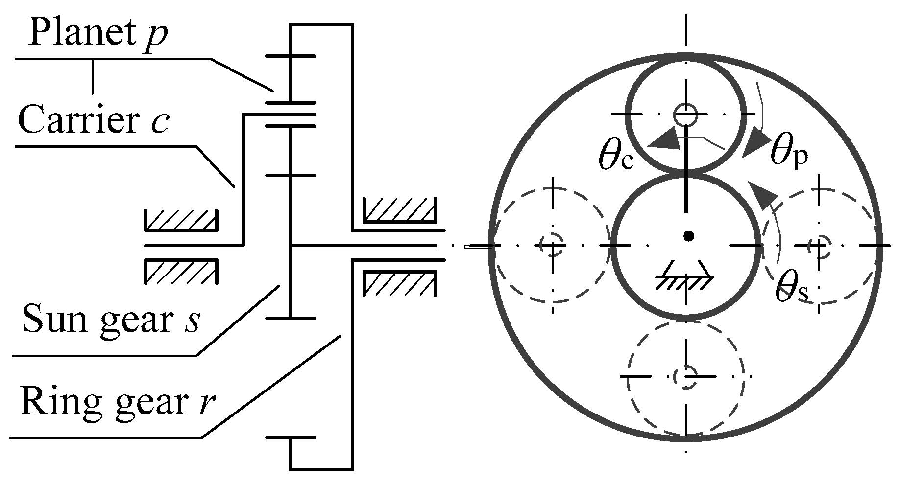
The 2K-H planetary gear reducer (shown in Figure 1), as an example of a typical joint system, is the current study object. The system is composed of four parts: sun gear (s), ring gear (r), planet carrier (c), and a certain number of planetary gears (p). Each planetary gear is fixed to the planet carrier through bearing, and can be freely rotated relative to the carrier. In order to establish the joint dynamics model of the planetary gear drive, the following assumptions are made:
- (1)
- Each gear in joints is considered to be a rigid gear, neglecting the plastic deformation during contact collision;
- (2)
- The elastic deformation of drive shaft is neglected, and the only effect of radial run-out caused by bearing clearance on the dynamic characteristics of system is considered;
- (3)
- The joint system is assumed to be a planar system. In other words, the radial vibration at the bearing is equivalent to two-degree-of-freedom translational motion in the gear rotation plane, and the torsional vibration of gear is equivalent to single-degree-of-freedom rotation in the plane of rotation.
2.1. Multi-Clearance Coupling Model
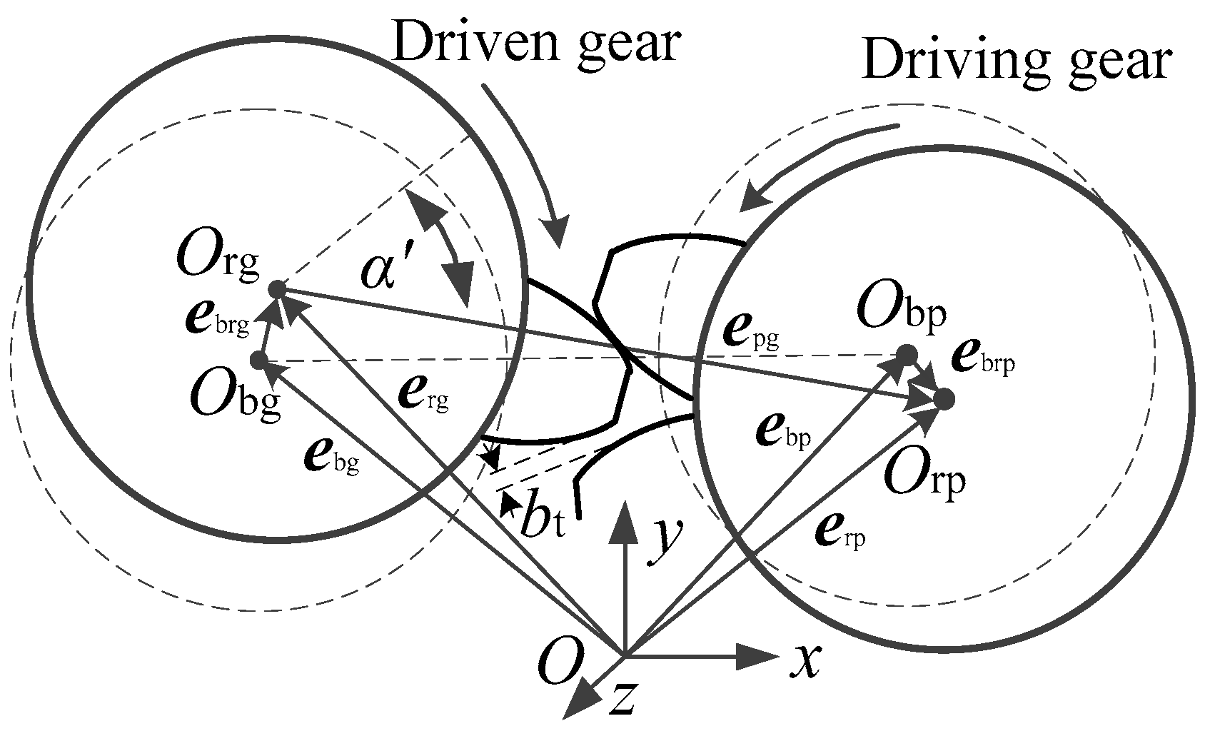
In a gear system, it is known that a radial clearance exists in bearings, and a backlash occurs between the teeth, so vibrations will occur in the clearance during the course of movement. Then the radial vibration at bearing lead to the change of gear’s actual center distance, and the backlash will dynamically change. The appearance of dynamic backlash will affect the torsional vibration and even the whole vibration characteristics of the gear system. Therefore, the coupling clearance model with bearing radial clearance and backlash is established as shown in Figure 2.
Figure 2 shows the multi-clearance coupling model of a single-pair gear pair. Here, gear p represent the driving gear and gear g represents the driven gear. Obp and Obg are defined as the bearing centers of the driving and driven gear, respectively. It is noteworthy that Orp (the rotation center of the driving gear) and Org (the rotation center of the driven gear) will deviate from the corresponding bearing center, due to the influence of the bearing’s radial clearance. Thus, the vectors of above four points in the global inertia coordinate are defined as ebp, ebg, erp and erg, respectively. Then ebrp and ebrg define the radial clearance vectors which is the displacement error of diving and driven gear relative to bearing, respectively. Thus, the equations are written as:
The relative displacement relation between gear shaft and bearing in the radial direction can be represented as follows:
where cri (i = p, g) represents bearing radial clearance of driving or driven gear.
Thus, the function fr (δri) can be used to describe the state of gear shaft and bearing during the collision:
In Equation (4), the first condition represents the gear shaft and bearing without collision, while the second and third conditions represent a critical contact (impact force is zero) and a contact condition, respectively. In Figure 2, the actual center distance epg between gears has changed due to the radial offset of the gear:
When the gear standard center distance is A0, and the initial engagement angle is α0. With the change of center distance, the actual meshing angle α’ of gear varies as the following equation:
According to the involute geometry, taking the initial backlash b0 into consideration, the dynamic backlash bt can be expressed as:
and in the global coordinate system, the relative meshing displacement of driving and driven gear can be expressed as:
where Rp’ and Rg’ are the radius of driving and driven gear reference circle respectively. α′ is the actual pressure angle. θp and θg are the angular displacement of driving and driven gear, respectively. ebrpx and ebrpy are components of clearance vector ebrp in the x-axis and y-axis directions, respectively. ebrgx and ebrgy are components of clearance vector ebrg in the x-axis and y-axis direction, respectively.
Finally, the backlash function fg (gt) is used to describe the motion state during gear meshing as shown in Equation (9):
In Equation (9), the first condition represents normal gear engagement, while the second and third conditions represent the occurrence of separation phenomenon of gear pair and double-sided impacts between a gear pair.
2.2. System Dynamics Model
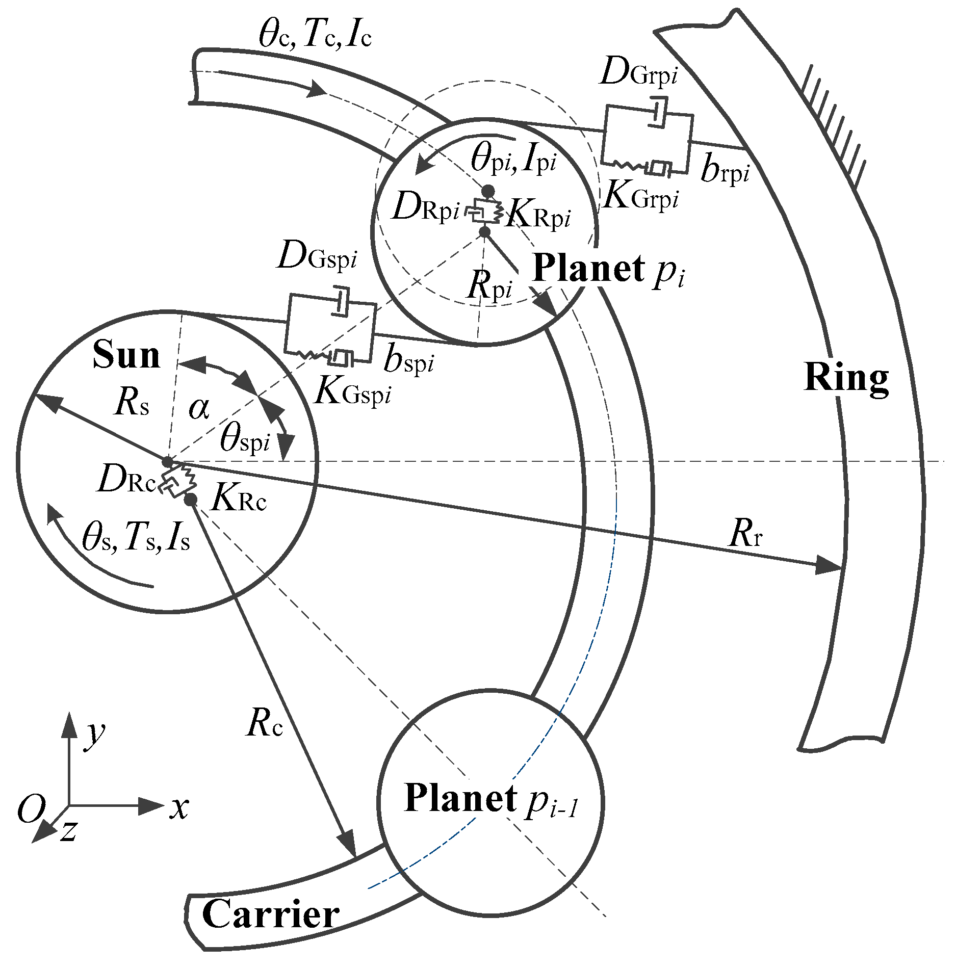
In Figure 3, there are np number of planetary gears. Each gear body j (j = s, pi, c) is modeled as a rigid gear radius Rj, angular displacement θj, and mass moment of inertia Ij. External torques Ts and Tc represent the input and output values. Between the planetary gear pi and gear n (s or r), KGnpi, DGnpi and bnpi are the periodically time-varying meshing stiffness, the viscous damper coefficient and backlash, respectively. α is theoretically pressure angle. KRpi and DRpi are the nonlinear stiffness and damping of the radial contact collision model at the planetary gear bearing, respectively. θspi is the initial phase angle of planetary gear relative to sun gear. Rr is the radius of the ring gear. KRc and DRc are the nonlinear stiffness and the damping of the carrier output shaft and bearing radial contact collision model, respectively.
The equations of motion of planetary system are written as follows:
In these equations, i = 1, 2, …, np, and in Figure 3, θcpi (t) = θpi (t) − θc (t) represents rotation angle of planetary gear with respect to carrier. Here, Icp = Ic + np (Ip + Rc2mp) is equivalent mass moment of inertia of carrier.
In these equations, the radial collision stiffness KRk (k = c, pi) could be obtained by collision experiment of two spheres, it is defined as:
where, υik and Eik (i = b, j) are Poisson’s ratio and elastic modulus of center element i, respectively. The variable b represents bearing, and j represents shaft.
The damper coefficients of radial collision, namely, DRc and DRpi are defined as:
where cek is the coefficient of restitution, is the initial relative velocity at the collision location.
The time-varying meshing stiffness KGh (h = spi, rpi) between gear teeth is given by:
where, kGmk is average meshing stiffness, kGah is time-varying meshing stiffness, ωGh is gear meshing frequency. φGh is initial phase of variable stiffness (φGh = 0 in general).
DGspi and DGrpi are the non-linear dampers of gear meshing. In order to prevent the discontinuity of damping force during the meshing process and avoid the phenomenon in which the impact force of linear damping model is not equal to zero in critical contact state, the nonlinear damping force can be expressed as:
where DGmh is the maximum damping coefficient; dh is the maximum embedding depth and values as 0.1 mm, and βh is defined as βh = fgh (gth)/dh.
3. Results
It is known that planetary gears are used in space manipulators and drive mechanisms, primarily for rotating motion of space mechanisms. As the kinematic accuracy and reliability requirements are extremely high in space mechanisms, the vibrations within joint, which are most likely to have a significant impact on the operational stability of the entire spacecraft, are not negligible. Therefore, in this section, the influence of multi-clearance coupling effects on vibration characteristics of a planetary gear drive is studied by analyzing the vibration characteristics of the planetary gear joint and the influence of velocity, clearance and load on its vibration characteristics. In this paper, the Newmark method is used to solve the dynamic model. This algorithm is unconditionally stable under certain parameters and is helpful to solve high-dimensional nonlinear differential algebraic equations. The radial and torsional acceleration curves of planetary gear train are obtained by simulation, and then the corresponding vibration spectrum is obtained by Fast Fourier Transform (FFT). To ensure the versatility of modeling and analysis methods, here, the main parameters of numerical simulation are referred to Kahraman’s simulation case [11], as shown in Table 1.
In order to get theoretical velocity of planetary gear and planet carrier, the general formula for planetary gear ratio calculation is as follows:
where, is the transmission ratio of the sun gear and the ring gear in inverted gear train. ns, nr and nc represent the velocities of sun gear, ring gear and planet carrier respectively. And m is the number of external meshing between sun gear and ring gear in the inverted gear train. zs, zr and zp represent the number of teeth of sun gear, ring gear and planetary gear, respectively, and the values are shown in Table 1. Here, due to the ring gear is fixed, nc is taken as zero. To verify the reliability of dynamic model and calculation results, a verification simulation experiment was performed. When the ring gear and frame is relatively static, the sun gear velocity is taken as 30°/s, and the theoretical value of planet carrier velocity is taken as ωc = 9.808°/s. Under the same condition, the numerical results of planet carrier velocity is ω′c = 9.809°/s. It can be seen that the motion law of dynamic model in this paper is realistic and the accuracy of dynamic model is verified.
3.1. Analysis of Coupling Vibration of Transmission Joint
As the multi-clearance coupling relation in dynamic model of planetary gear drive joint is considered, there is a complex coupling vibration relation inside the transmission joint. Therefore, the next step is finding the coupling law of internal vibration of transmission joint by spectrum analysis. Here, assuming that the connection between sun gear and drive motor is ideal, there are four clearances in the drive joint, namely, the backlash between sun gear and planetary gear, taking bsp = 200 μm; the backlash exists between planet and ring gear, taking brp = 200 μm. The radial clearance between the planetary gear shaft and bearing of the planet carrier, ccp = 200 μm; The radial clearance between planet carrier shaft and output bearing, cc = 200 μm. As the drive velocity of space mechanism is slow, the drive velocity of sun gear is taken as 30°/s.
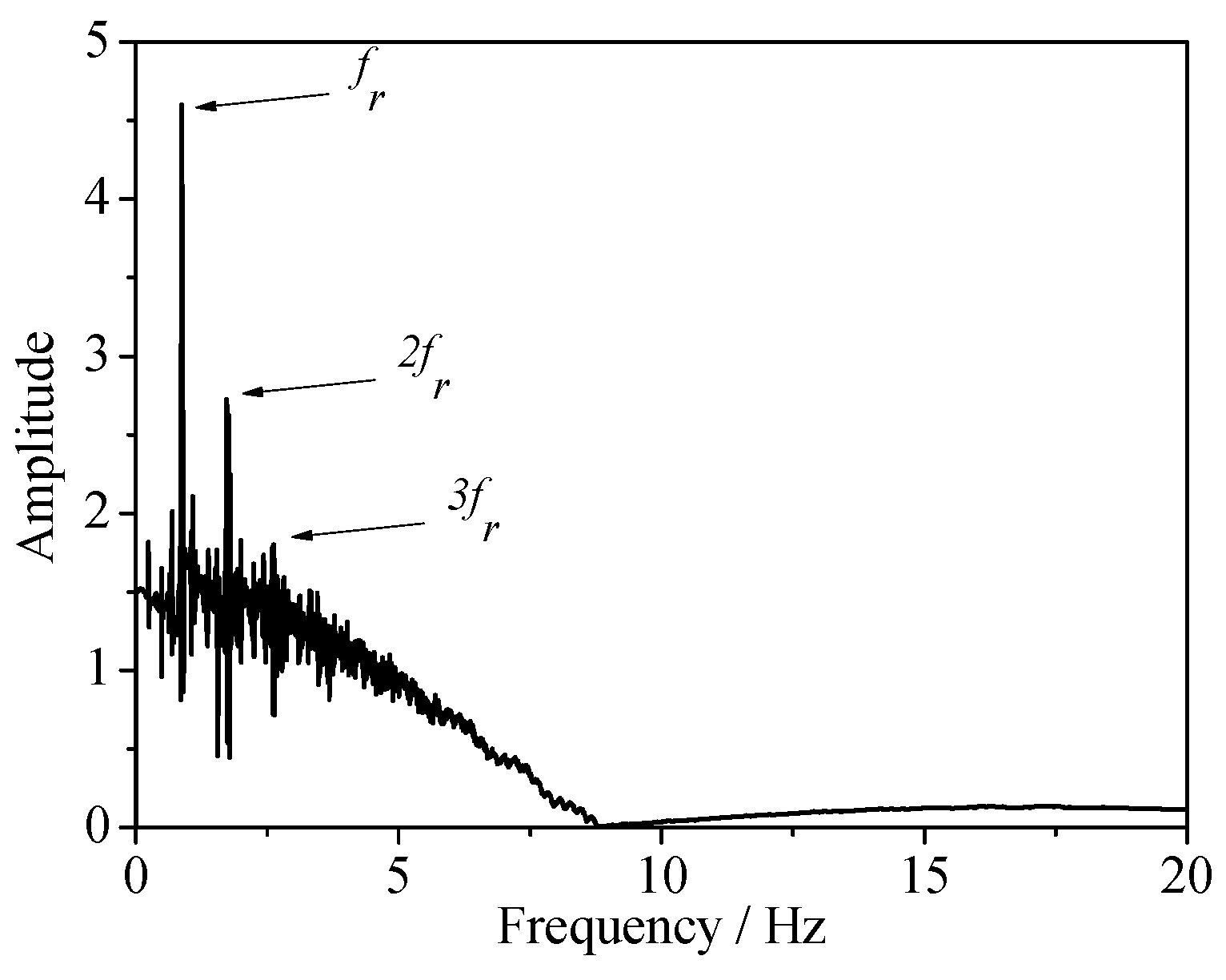
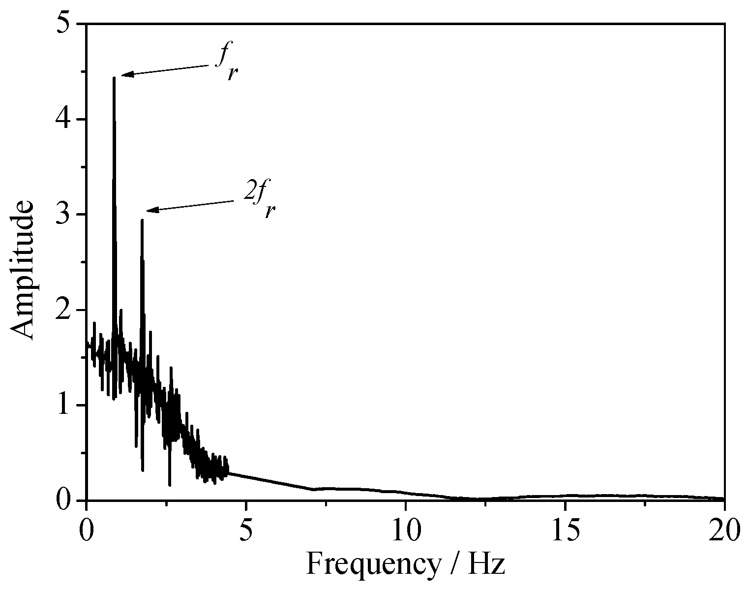
Figure 4, Figure 5, Figure 6 and Figure 7 show the vibration frequency spectra of the planetary gear in the case of an empty inertial load. Figure 4 shows the radial vibration frequency spectrum of the planet carrier’s bearing, in which the abscissa represents frequency and the ordinate represents the amplitude, reflecting the radial vibration characteristics of the planet carrier relative to the bearing. It can be seen from the figure that the radial vibration frequency spectrum of the planet carrier mainly contains the frequency fr of radial clearance vibration, and the two times and three times the frequency of fr. Among them, the frequency of radial clearance is the vibration frequency of the rotating shaft and bearing in a continuous contact state, and in this case, fr = 0.87 Hz. In addition, this figure shows a higher harmonics of fr cause by the mutual coupling between the radial vibration of planet carrier and planet.
Figure 5 shows the radial vibration frequency of the planetary gear relative to the bearing. The frequency fr of the radial clearance vibration is also included in the frequency spectrum for the planet shaft and the bearings are also in a continuous contact state at low velocity. Meanwhile, since the planetary gears are mounted on the planet carrier, the radial vibration of the planet carrier not only directly affect the radial vibration of planet as a whole, but also be affected by the radial vibration of the planetary gear bearings. In addition, due to the mutual radial vibration coupling between the planet carrier and planet, the radial vibration of the planet also shows two times the frequency fr.
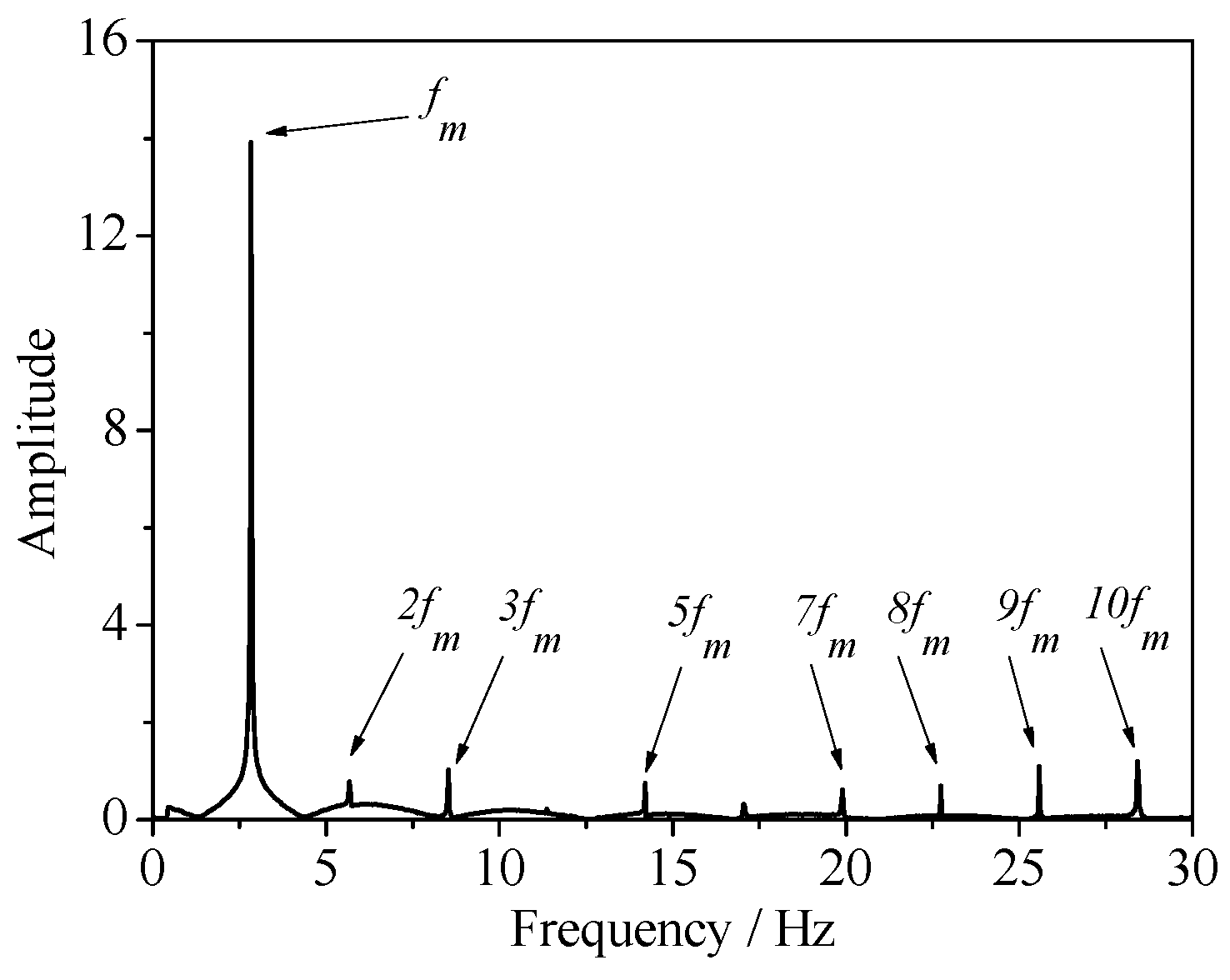
Figure 6 shows the frequency spectrum of torsional vibration of the planet carrier, which reflects the vibration characteristics in the direction of rotation when the planet carrier rotates at the output velocity. The rotary motion of the planet carrier is driven by meshing among the planet, sun gear and ring gear, so its torsional vibration characteristics are mainly related to the meshing frequency fm among gears. It can be seen from the figure that the torsional vibration frequency spectrum of the planet carrier includes the gear meshing frequency fm, 2 fm, 3 fm, and so on, where the amplitude of meshing frequency fm is the largest, and it is worth mentioning that a higher harmonics occurs due to the influence of time-varying meshing stiffness and backlash.
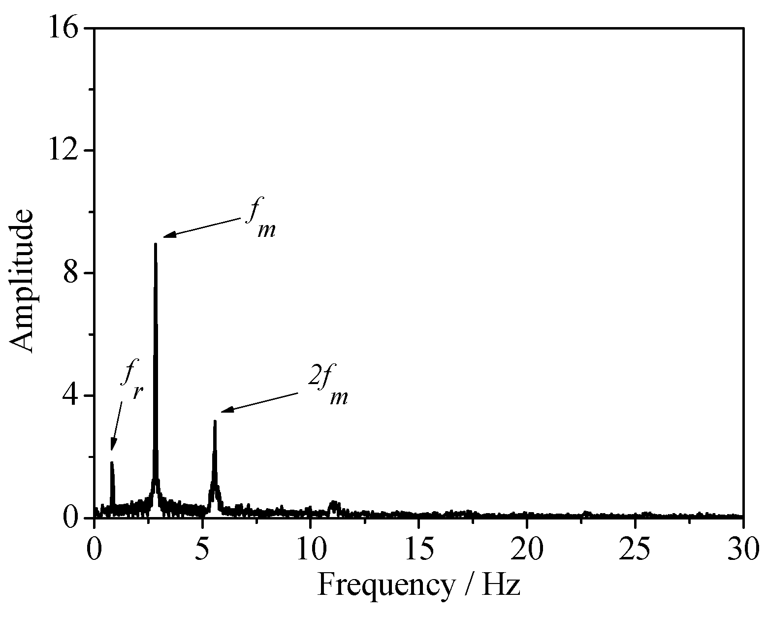
Figure 7 shows the torsional vibration frequency spectrum of the planetary gear, which not only contains the gear meshing frequencies fm and 2 fm, but also reflects the frequency fr of the radial clearance vibration. It shows that radial vibration of planetary gears causes a change in backlash, resulting in dynamic backlash fluctuations that then influence the torsional vibration characteristics of planetary gears. It can be seen that although the radial and torsional vibrations of multi-clearance gear systems are not in the same direction, there is still a coupling relationship between them.
3.2. Effect of Velocity on Joint Vibration Characteristics
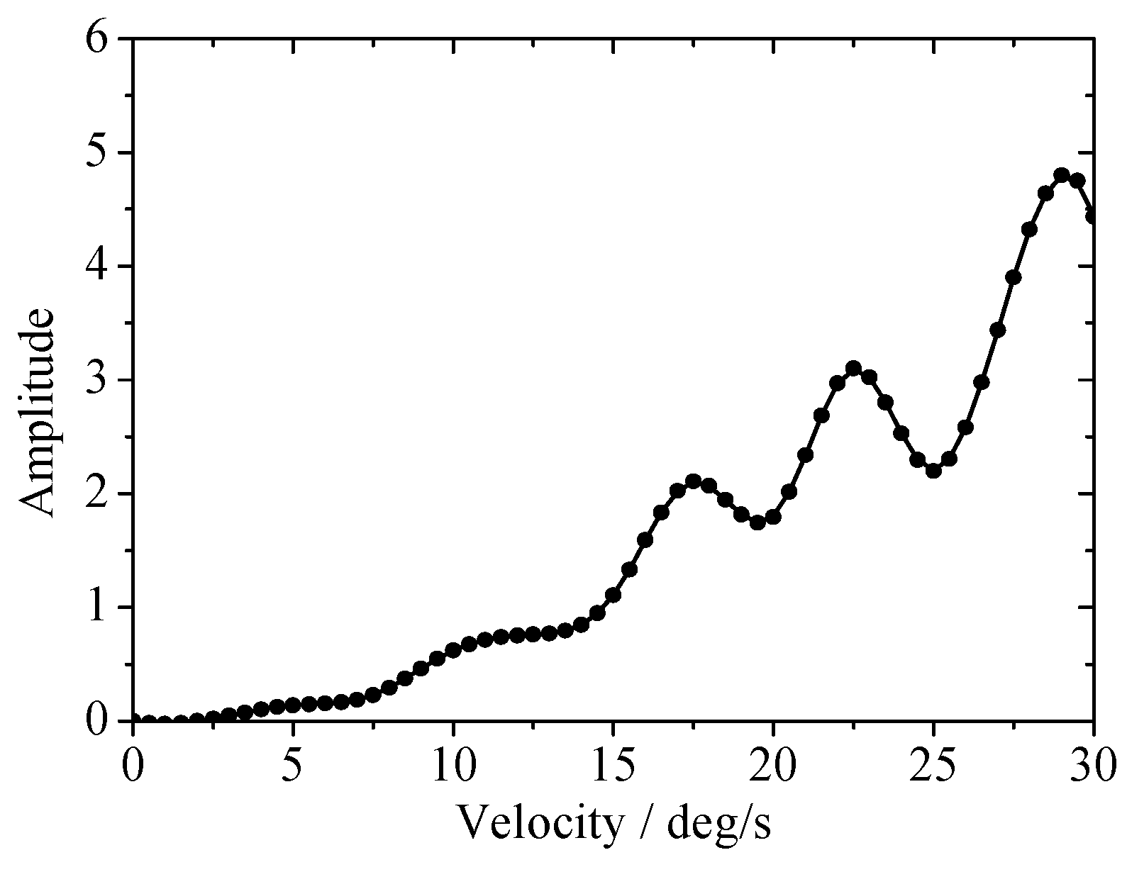
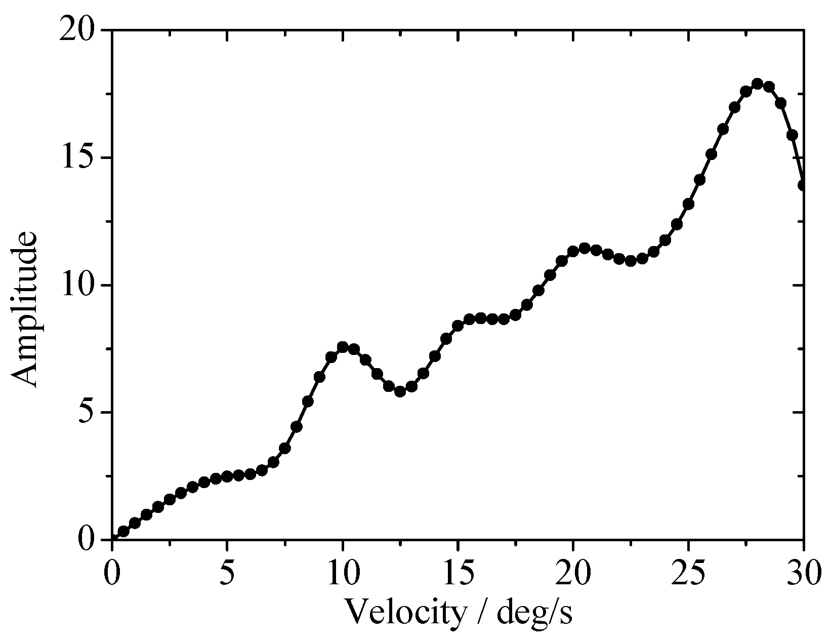
According to the analysis presented in the previous section, it can be seen that planet carrier is coupled with the planetary gear vibrations, and the radial and torsional vibration of the planetary gear itself also has a coupled relation. These coupling vibrations may cause resonance phenomena under certain conditions. Since the space mechanisms are operated under environmental loads and in diverse working states, the rotational velocities of transmission joints are quite different in order to accomplish different tasks like attitude-adjusting, tracking, pointing and so on, so this section analyzes the influence of rotational velocity on the vibration characteristics of joints. It reflects the variation of the vibration peak values of the system steady-state response at different velocities. It is assumed that the radial clearance of the joint interior and backlash are taken as 200 μm. In empty-load state, the velocity range is from 0°/s to 30°/s. The amplitude-frequency response curves of planetary gears are shown in Figure 8, Figure 9, Figure 10 and Figure 11.
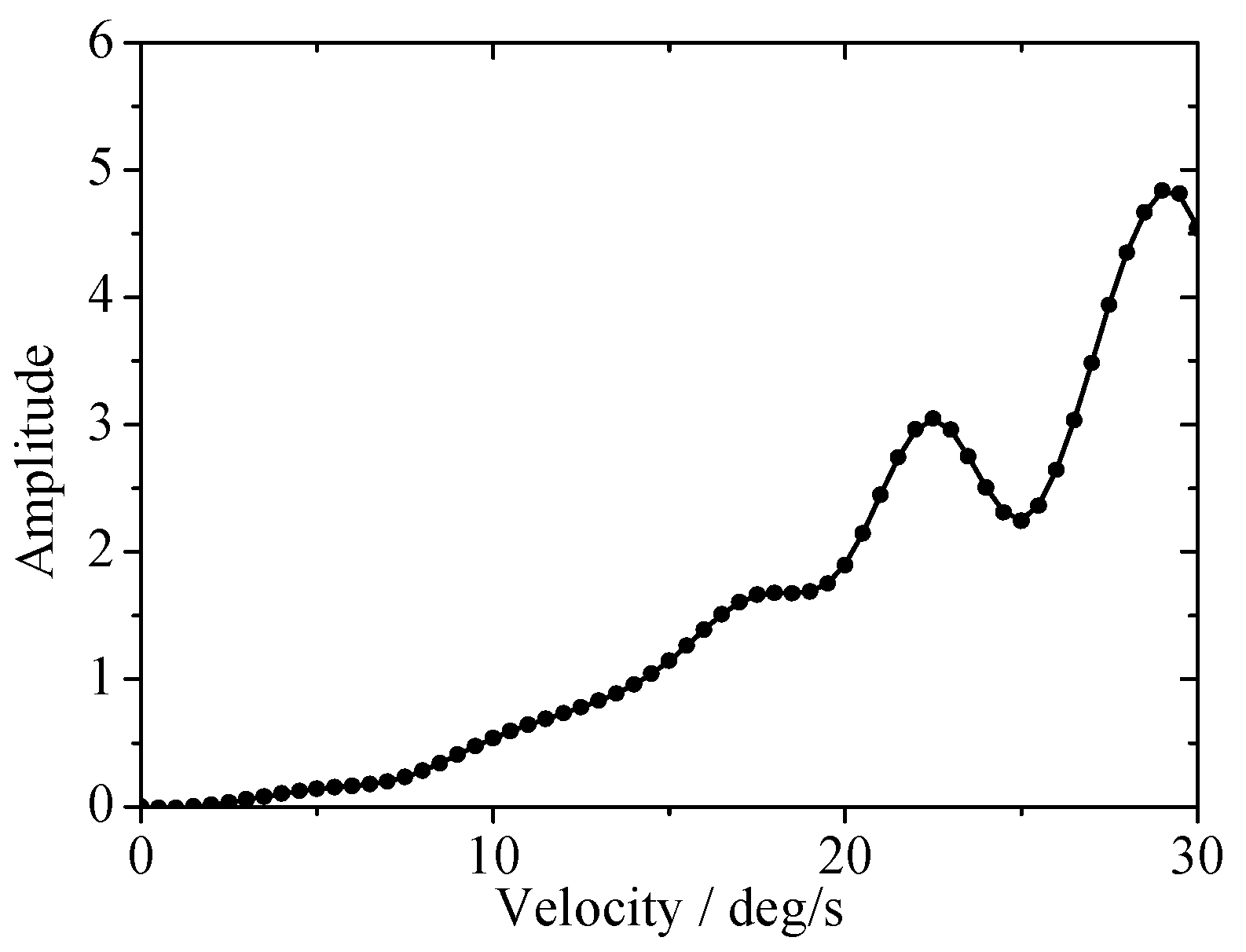
Figure 8 and Figure 9 show the amplitude-response curves of the radial vibration of the planet carrier and planetary gear at different driving velocities, respectively. These graphs display the change law of the amplitude of frequency fr at different driving velocities. By comparing the two graphs, it can be found that vibration peaks occur at specific velocities. Both graphs show the vibration peaks’ value are nearly equal at the same velocities. It shows that the radial vibration of the planet carrier is mainly caused by the radial vibration of planet. Compared to Figure 8, there is a new vibration peak at a driving velocity of 17.5°/s in Figure 9. It can be inferred that this phenomenon is caused by the coupling effect of the radial vibration of the planet carrier and planet.
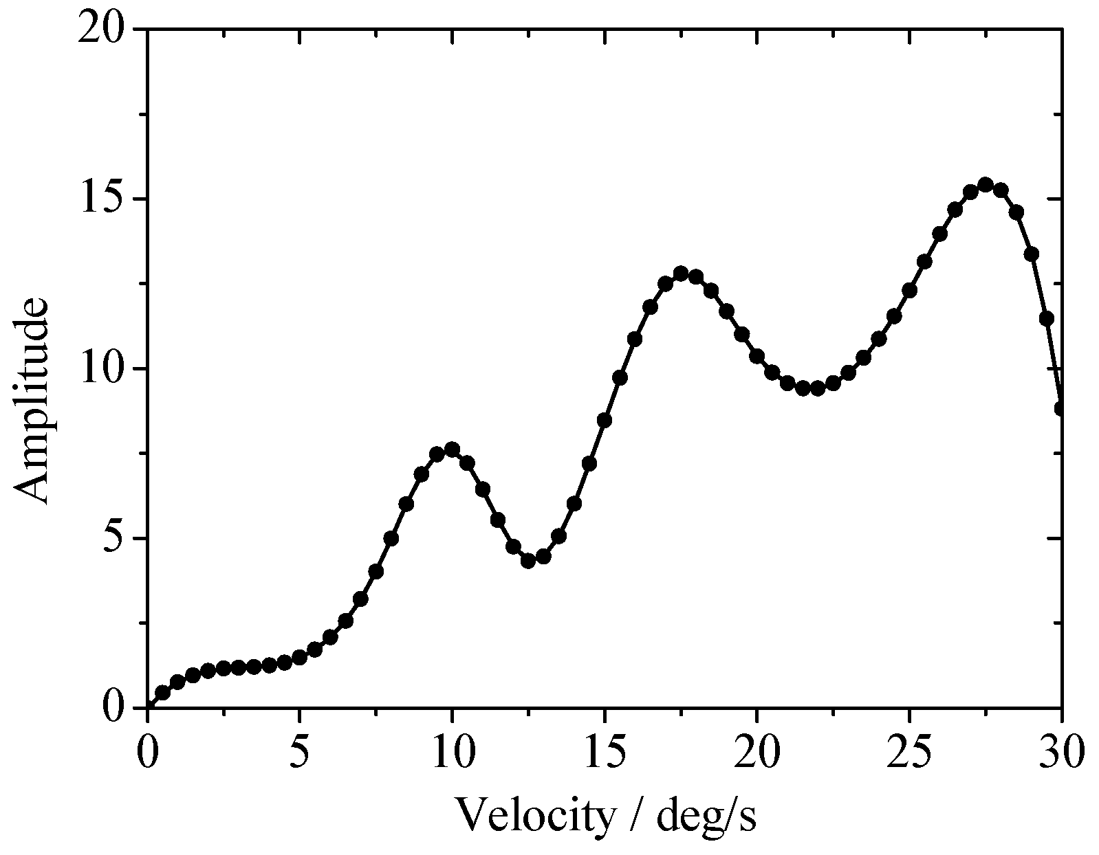
Figure 10 and Figure 11 show the amplitude-response curves of the torsional vibration of the planet carrier and planet at different driving velocities, respectively. It shows the change law of the amplitude of gear meshing frequency fm in the torsional vibration of planet carrier and planet at different driving velocities. As the curve shows, both graphs have vibration peaks when the driving velocity is close to 10°/s and 27.5°/s, and the same phenomenon can be found in Figure 11. It can be proved that the coupling relation of torsional vibration between the planet carrier and the planet makes the resonance phenomenon occur in the system when the velocities are close to 10°/s and 27.5°/s. Similar to Figure 9, a vibration peak also can be found when the driving velocity near 17.5°/s in Figure 11. It can be inferred that this phenomenon is caused by the coupling effect between the radial vibration and the torsional vibration of planet, when the driving velocity of the planet drive joint is close to 17.5°/s.
3.3. Influence of Clearance Size on Joint Vibration Characteristics
From the dynamic modeling process, it can be seen that the clearance size is also one of the major factors which have an influence on the vibration characteristics of joint systems. On the basis of the above analysis, it can be concluded that the coupling relation of vibrations between the planet carrier and planet gear is a significant factor. The radial vibration of planetary gears also has a coupling relation with their torsional vibration. Hence, this section will analyze the influence rule of clearance size on the coupling vibration of joint, providing a theoretical basis for the design of the joint system and reasonable selection of the clearance.
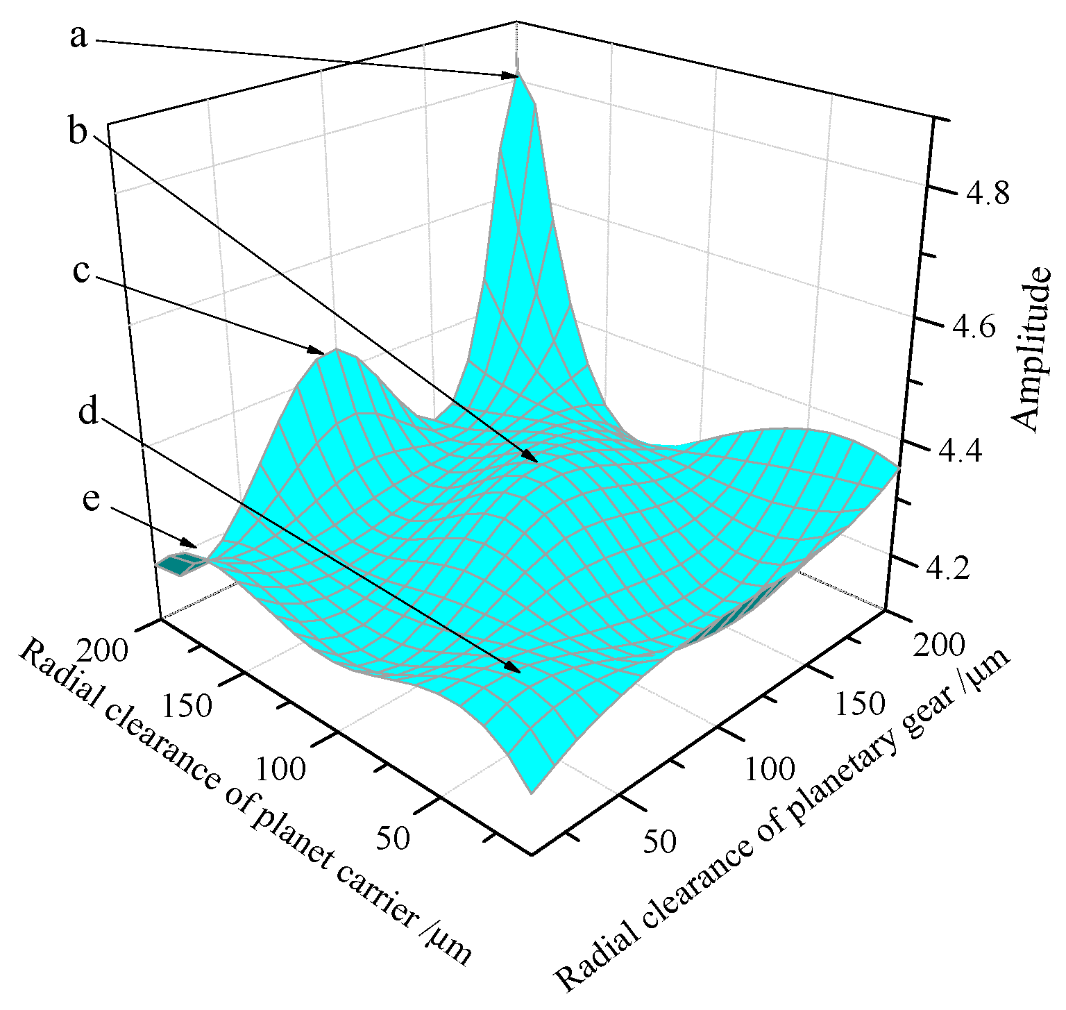
First, we will analyze the influence of radial clearance size of the planet carrier and planet on the coupling relation of radial vibration, taking the driving velocity as 29°/s, and the range of radial clearance of planet carrier and planet as 10 to 200 μm. The radial vibration response curves of planetary gears at different radial clearances are obtained, as shown in Figure 12.
In Figure 12, the x and y axes represent the radial clearance of the planet carrier and planet, respectively, and z axis represents the amplitude of the frequency of the radial vibration. There are totally five major vibration peaks in Figure 12. The a-point’s vibration peak is highest when cc = 200 μm and ccp = 200 μm, and other vibration peaks are represented by b, c, d and e. It can be concluded that the size of radial clearance has a significant effect on the radial coupling vibration, and the system will resonate when the radial clearance displays a specific combination.
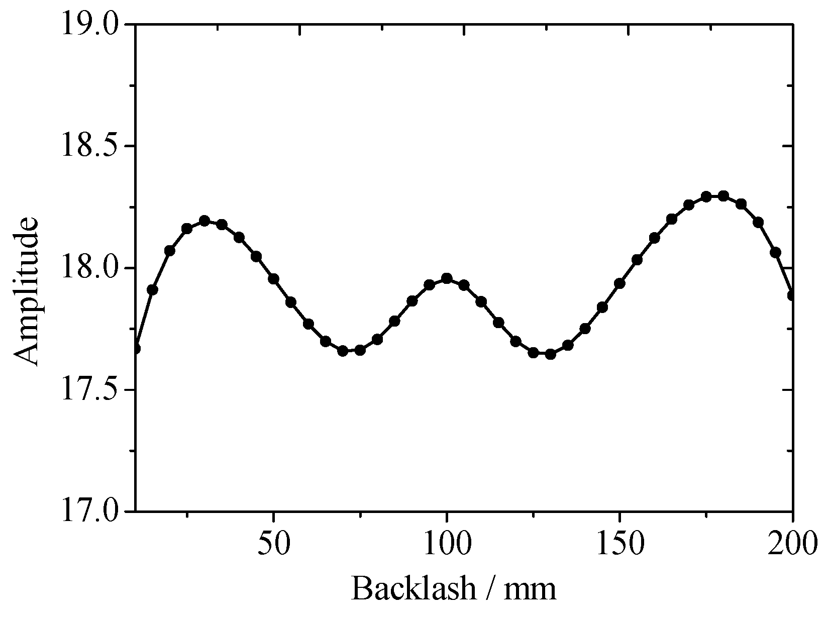
To study the influence of backlash size on the coupling relation of torsional vibration, we take the torsion vibration response curve of planet carrier as an example here. The driving velocity of the torsional vibration peak is taken as 27.5°/s according to the analysis presented in the previous section. It is considered that bsp = brp, and its variation range is 10 to 200 μm. The numerical calculation results are shown in Figure 12.
In Figure 13, the horizontal axis represents backlash, and vertical axis represents the amplitude of meshing frequency fm in torsional vibration of the planet carrier. It must also be noted that a vibration peak appears when the backlash is taken as 30, 100 and 180 μm. It can be seen that the effect of backlash size on the torsional vibration characteristics is very significant.
Through the above numerical calculation, it can be found that there is a coupling relation between the planetary gear’s radial and the torsional vibration. In other words, it indirectly verifies that the coupling between radial clearance and backlash is correct in the dynamic model. On the basis of the vibration characteristics of planet itself, this section aims to further study the influence of radial clearance and backlash’s size on the coupling vibration.
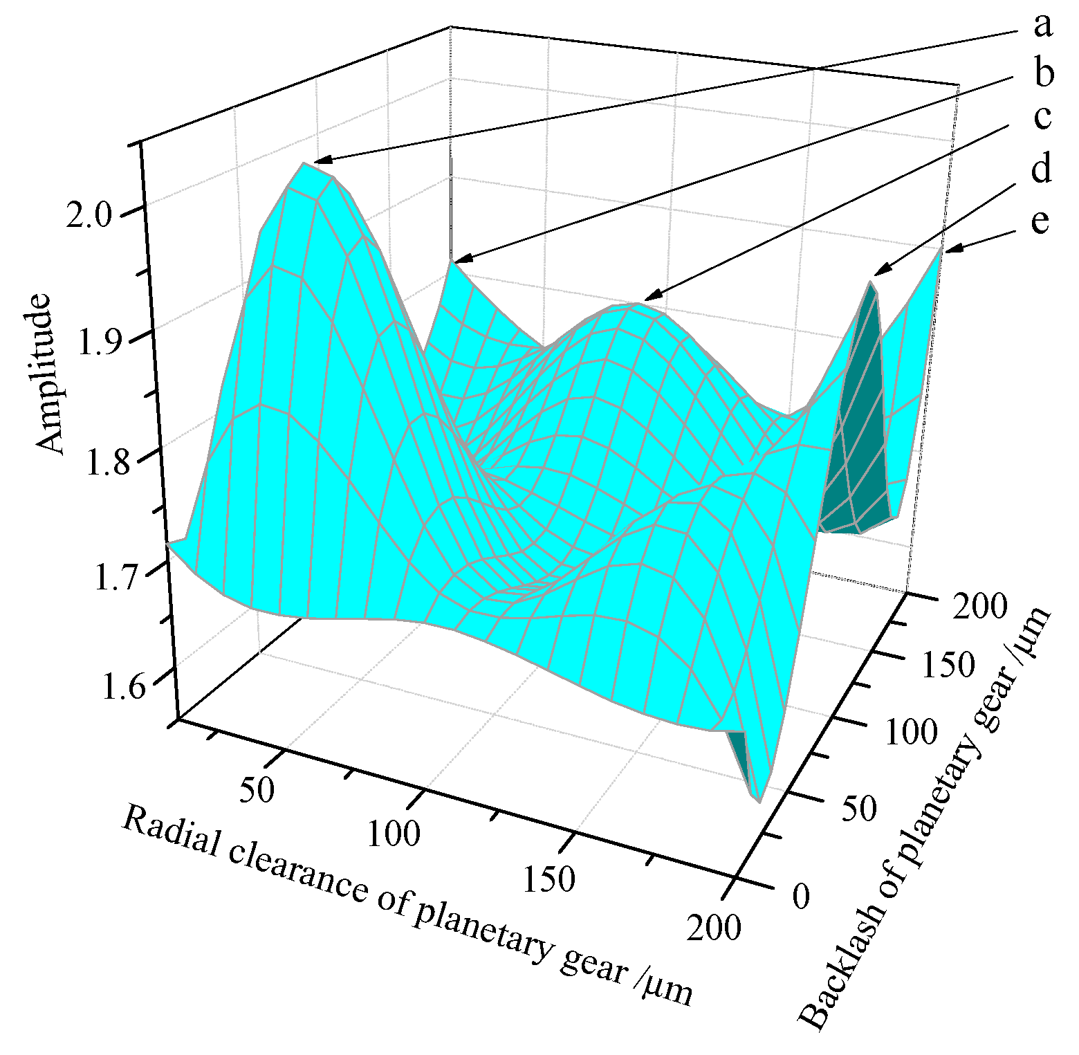
According to the analysis of Figure 9 and Figure 11, the driving velocity is taken as 17.5°/s for the radial and torsional vibration of planet shows a resonance phenomenon at this velocity, and the ranges of radial clearance and backlash of the planet are 10 to 200 μm, the amplitude variation rule of frequency fr of planets with different radial clearance and the backlash sizes is shown in Figure 14.
In Figure 14, x-axis and y-axis respectively indicate the sizes of radial clearance and backlash of planet, and the z-axis represents the frequency’s amplitude of the radial vibration of the planet. There are five vibration peaks in the figure, and the a-point vibration peak is highest at ccp = 40 μm and bsp = brp = 40 μm. It can be concluded that the sizes of the radial clearance and backlash have a significant effect on the coupling between the radial and torsional vibration of planet, and a large amplitude of vibration peak will occur when the clearance are in a specific combination.
3.4. Influence of Load on Joint Vibration Characteristics
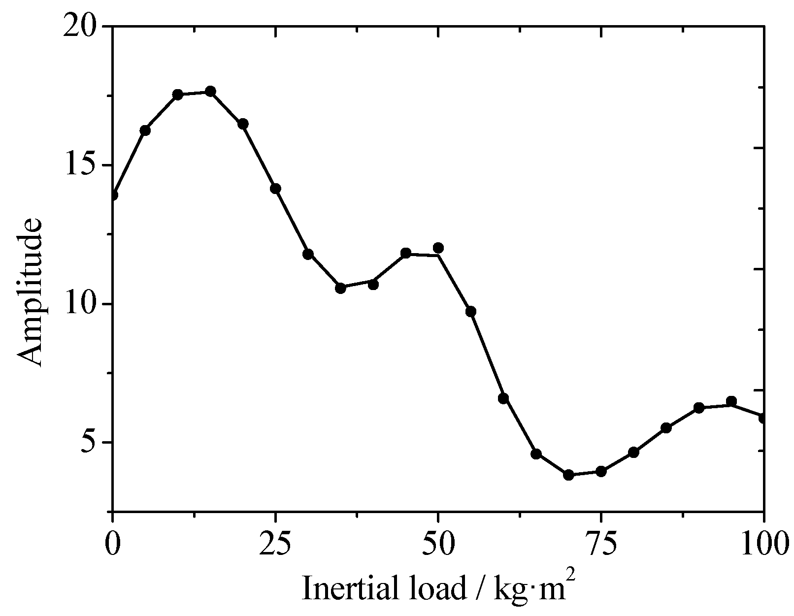
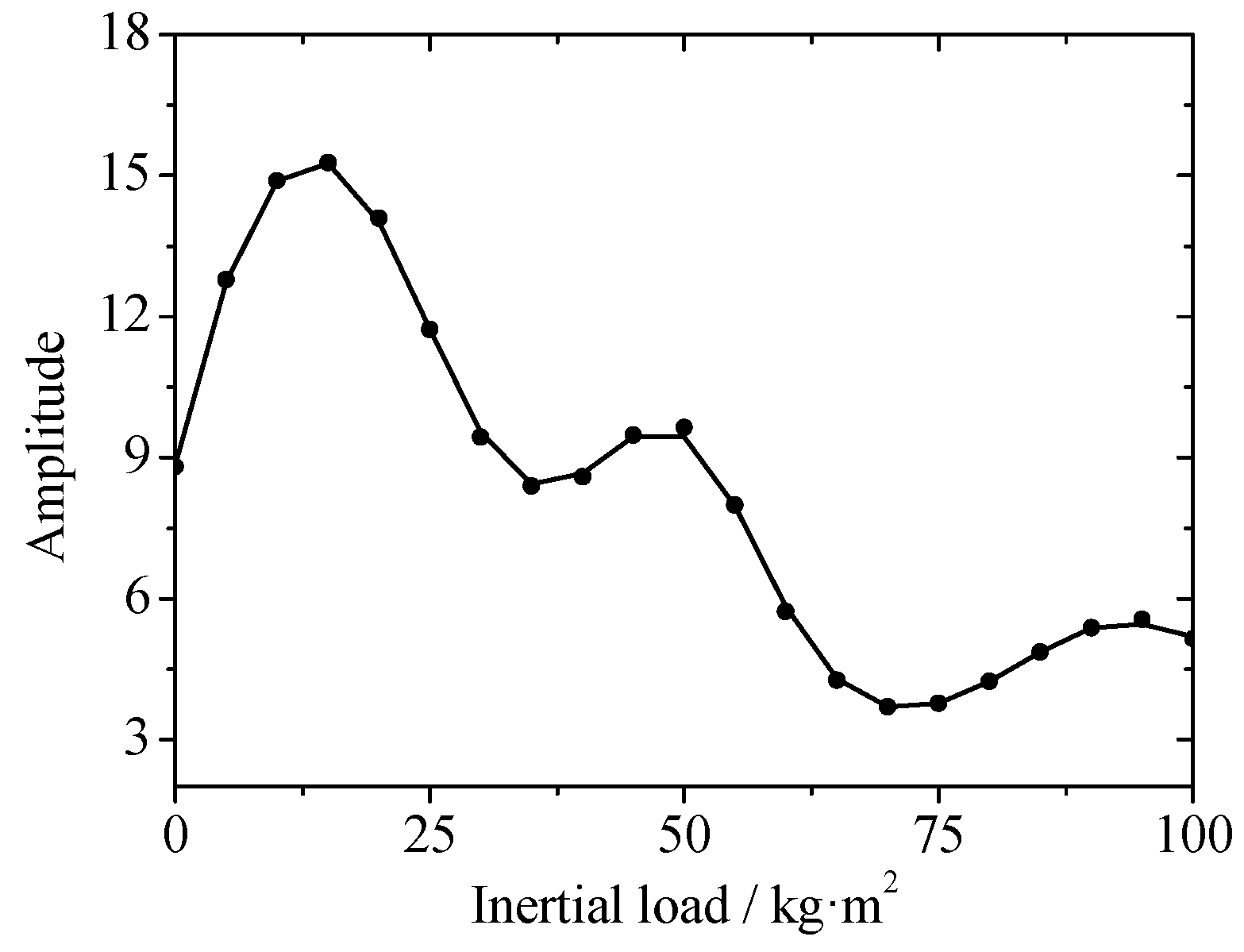
A typical spacecraft, such as a large space manipulator, will bear a certain inertial load during the execution of object-grabbing or object-transferring. The end of the satellite biaxial drive mechanism also has an antenna reflector, a camera or other loads. On the one hand these inertial loads are indispensable for the spacecraft; on the other hand, the vibration characteristics of joints will be affected during the course of motion due to the presence of inertial loads. Taking the single joint as an example, this section analyzes the influences of different inertial loads on the vibration characteristics of planetary gears. Here, the variation range of inertial load is taken as 0 to 100 kg·m2, the driving velocity is taken as 30°/s, both the radial clearance and the backlash are taken as 200 μm, and the numerical calculation results are shown in Figure 15, Figure 16, Figure 17 and Figure 18.
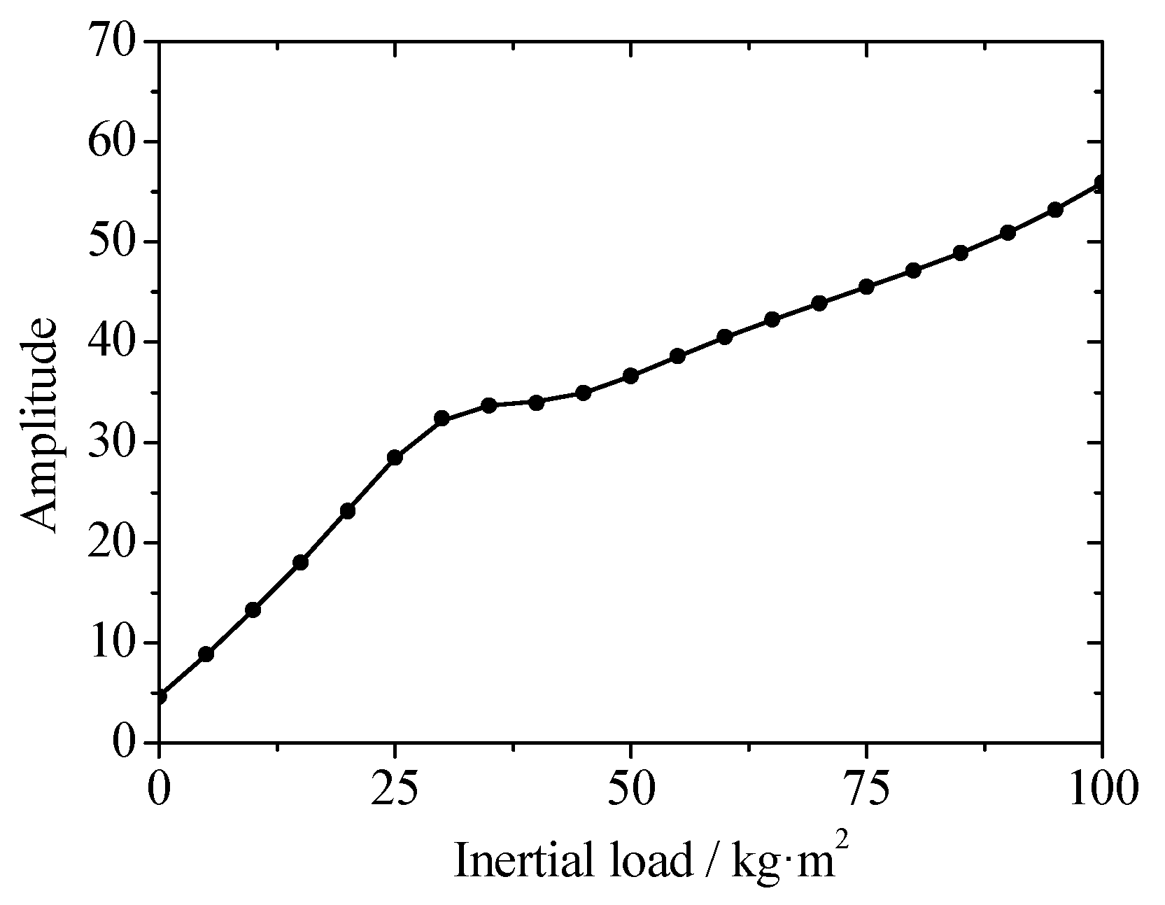
Figure 15 shows the change law of the frequency fr’s amplitude in the radial vibration of the planet carrier at different inertial loads. Since the inertial load is directly working on the planet carrier, with the increase of inertial load, the radial vibration amplitude of the planet carrier increases and the radial vibration will be more intense. This phenomenon is caused by the increase of inertial load, and the radial vibration of planet carrier can be alleviated only by reducing the inertial load.
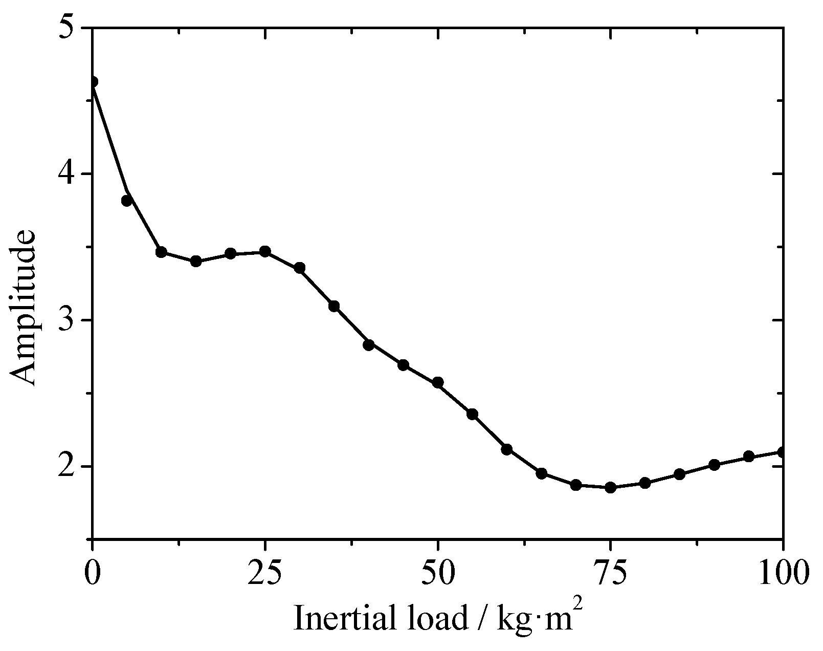
Figure 16 shows the change law of planetary gear radial vibration with different inertial loads. It can be seen from Figure 16 that the radial vibration amplitude of the planetary gear is reducing with the increasing inertia load. The reason is that the planet carrier is in a free vibration state in the radial direction without the inertial load, and four planetary gears mounted on the carrier are vibrating with the vibration of the planet carrier. When the system bears an inertial load, the joints are subjected to inertial forces in the radial direction, but the four evenly arranged planetary gears which are in the circumferential direction of planet carrier will dynamically balance the radial forces. In this condition, the changes of all planetary gear’s radial force are quite stable, and then the radial vibration of planetary gears will be reduced.
A similar phenomenon to the one seen in Figure 16 also could be seen in Figure 17 and Figure 18, in which the torsional vibrations of planet carrier and planetary gear are reduced as the inertia load increases. One reason is that the increase of inertia load results in the raise of gear meshing force and fewer off tooth and tooth back impacts. Another reason is that the dynamic backlash’s changes are weakening at any time due to the weakness of the radial vibration of the planetary gear, and the gear meshing process is more stable.
4. Conclusions
This paper sets up a new nonlinear dynamic model of planetary gear joints, in which the radial clearance of bearings, dynamic backlash and time-varying meshing stiffness are considered. The effects of multi-clearance coupling on the vibration characteristics of driving joint planetary gears are analyzed. In this paper, a coupling effect of the internal vibration of the transmission joint is found in the frequency domain. The effects of velocity, clearance size and load on the joint vibration characteristics of planetary gear drives are analysed. The conclusion of the current study can be summarized as follows:
- At some specific velocities, resonance may occur between the vibration of the planet carrier and the planetary gear, and there is a coupling relation between the radial and torsional vibrations of the planetary gear itself;
- The clearance may cause nonlinearities in the system dynamic and changes in the vibration amplitude. Vibration peaks occur when the radial vibration of the planet carrier and planetary gears have specific radial clearance sizes. The change of backlash size causes a torsional vibration peak between the planet carrier and planetary gear. The radial and torsional vibration of planetary gears also produce a vibration peak with certain radial clearance and backlash combinations;
- Due to the special structure of planetary gears, the radial vibration amplitude of the output will increase when the load is heavy, but the amplitude of torsional vibration will decrease. Therefore, when the inertia load is heavy, the system’s rotation accuracy and stability are good, but when in empty-load or light-load states, the operating strategies also need to be adjusted to ensure operational reliability.
An inherent characteristic analysis of planetary gears with multi-clearance coupling will be developed by modal analysis in future work.
Author Contributions
Conceptualization, H.Z.; Data curation, J.F.; Formal analysis, C.Q. and S.D.; Funding acquisition, J.F.; Investigation, C.Q.; Project administration, S.D. and B.Y.; Resources, S.D.; Validation, J.F. and B.Y.; Writing–original draft, H.Z. and C.Q.; Writing–review & editing, H.Z.
Funding
This research was supported by State Key Laboratory of Robotics and System (HIT) (Grant No. SKLRS-2017-KF-15), Science and Technology on Space Intelligent Control Laboratory (Grant No. ZDSYS-2017-08), National Natural Science Foundation of China (NSFC) (Grant No. 51575126; 51605133; 51705127), and Graduate Innovative Ability Training Project of Hebei Province (Grant No. CXZZSS2018025).
Acknowledgments
The authors would like to thank the research grant from Spacecraft Dynamics Design and Simulation Lab (SDDSL) of HIT.
Conflicts of Interest
The authors declare no conflict of interest.
References
- Chen, Z.; Shao, Y. Dynamic simulation of planetary gear with tooth root crack in ring gear. Eng. Fail. Anal. 2013, 31, 8–18. [Google Scholar] [CrossRef]
- Pan, B.; Yu, D.; Sun, J. Research on dynamic modeling and analysis of joint in large space manipulator. J. Asrton. 2010, 31, 2448–2455. [Google Scholar] [CrossRef]
- Parenti-Castelli, V.; Venanzi, S. Clearance influence analysis on mechanisms. Mech. Mach. Theory 2005, 40, 1316–1329. [Google Scholar] [CrossRef]
- Bai, Z.; Zhao, Y.; Wang, X. Wear analysis of revolute joints with clearance in multibody systems. Sci. China Phys. Mech. Astron. 2013, 56, 1581–1590. [Google Scholar] [CrossRef]
- Megahed, S.M.; Haroun, A.F. Analysis of the dynamic behavioral performance of mechanical systems with multi-clearance joints. J. Comput. Nonlinear Dyn. 2012, 7, 354–360. [Google Scholar] [CrossRef]
- Zhang, H.; Tian, J.; Zhou, J.; Zhao, Y.; You, B. Dynamic and experimental investigation of gear-rotor system with multiple clearances coupled. Chin. J. Mech. Eng. 2017, 53, 29–37. [Google Scholar] [CrossRef]
- Chaker, A.; Mlika, A.; Laribi, M.A.; Romdhane, L.; Zeghloul, S. Clearance and manufacturing errors’ effects on the accuracy of the 3-RCC spherical parallel manipulator. Eur. J. Mech. A-Solids 2013, 37, 86–95. [Google Scholar] [CrossRef]
- Kahraman, A. Load sharing characteristics of planetary transmission. Mech. Mach. Theory 1994, 29, 1151–1165. [Google Scholar] [CrossRef]
- Yuksel, C.; Kahraman, A. Dynamic tooth loads of planetary gear sets having tooth profile wear. Mech. Mach. Theory 2004, 39, 695–715. [Google Scholar] [CrossRef]
- Al-Shyyab, A.; Kahraman, A. Non-linear dynamic analysis of a multi-mesh gear train using multi-term harmonic balance method: Sub-harmonic motions. J. Sound Vib. 2005, 284, 151–172. [Google Scholar] [CrossRef]
- Al-Shyyab, A.; Kahraman, A. Non-linear dynamic model for planetary gear sets. Proc. Inst. Mech. Eng. K-J. Multi-Body Dyn. 2007, 221, 567–576. [Google Scholar] [CrossRef]
- Ligata, H.; Kahraman, A.; Singh, A. An experimental study of the influence of manufacturing errors on the planetary gear stresses and planetary load sharing. J. Mech. Des. 2008, 130, 1–9. [Google Scholar] [CrossRef]
- Inalpolat, M.; Kahraman, A. A dynamic model to predict modulation sidebands of a planetary gear set having manufacturing errors. J. Sound Vib. 2010, 329, 371–393. [Google Scholar] [CrossRef]
- Hotait, M.A.; Kahraman, A. Experiments on the relationship between the dynamic transmission error and the dynamic stress factor of spur gear pairs. Mech. Mach. Theory 2013, 70, 116–128. [Google Scholar] [CrossRef]
- Li, S.; Kahraman, A. A tribo-dynamic model of a spur gear pair. J. Sound Vib. 2013, 332, 4963–4978. [Google Scholar] [CrossRef]
- Ambarisha, V.K.; Parker, R.G. Nonlinear dynamics of planetary gears using analytical and finite element models. J. Sound Vib. 2007, 302, 577–595. [Google Scholar] [CrossRef]
- Gill-Jeong, C.; Parker, R.G. Influence of bearing stiffness on the static properties of a planetary gear system with manufacturing errors. KSME Int. J. 2004, 18, 1978–1988. [Google Scholar] [CrossRef]
- Canchi, S.V.; Parker, R.G. Effect of ring-planet mesh phasing and contact ratio on the parametric instabilities of a planetary gear ring. J. Mech. Des. 2007, 130, 014501. [Google Scholar] [CrossRef]
- Liu, G.; Parker, R.G. Nonlinear dynamics of idler gear systems. Nonlinear Dyn. 2008, 53, 345–367. [Google Scholar] [CrossRef]
- Guo, Y.; Parker, R.G. Dynamic analysis of planetary gears with bearing clearance. J. Comput. Nonlinear Dyn. 2012, 7, 041002. [Google Scholar] [CrossRef]
- Ericson, T.M.; Parker, R.G. Experimental measurement of the effects of torque on the dynamic behavior and system parameters of planetary gears. Mech. Mach. Theory 2014, 74, 370–389. [Google Scholar] [CrossRef]
- Cooley, C.G.; Liu, C.; Dai, X.; Parker, R.G. Gear tooth mesh stiffness: A comparison of calculation approaches. Mech. Mach. Theory 2016, 105, 540–553. [Google Scholar] [CrossRef]
- Pappalardo, C.M.; Guida, D. Control of nonlinear vibrations using the adjoint method. Meccanica 2017, 52, 2503–2526. [Google Scholar] [CrossRef]
- Pappalardo, C.M.; Guida, D. Adjoint-based optimization procedure for active vibration control of nonlinear mechanical systems. J. Dyn. Syst. Meas. Control 2017, 139, 081010. [Google Scholar] [CrossRef]
- Ouyang, H.; Richiedei, D.; Trevisani, A.; Zanardo, G. Discrete mass and stiffness modifications for the inverse eigenstructure assignment in vibrating systems: Theory and experimental validation. Int. J. Mech. Sci. 2012, 64, 211–220. [Google Scholar] [CrossRef]
- Palermo, A.; Mundo, D.; Hadjit, R.; Desmet, W. Multibody element for spur and helical gear meshing based on detailed three-dimensional contact calculations. Mech. Mach. Theory 2013, 62, 13–30. [Google Scholar] [CrossRef]
- Shweiki, S.; Palermo, A.; Mundo, D. A study on the dynamic behaviour of lightweight gears. Shock Vib. 2017, 2017, 1–12. [Google Scholar] [CrossRef]
- Vivet, M.; Mundo, D.; Tamarozzi, T.; Desmet, W. An analytical model for accurate and numerically efficient tooth contact analysis under load, applied to face-milled spiral bevel gears. Mech. Mach. Theory 2018, 130, 137–156. [Google Scholar] [CrossRef]
- Wei, J.; Zhang, A.; Qin, D.; Lim, T.; Shu, R.; Lin, X.; Meng, F. A coupling dynamics analysis method for a multistage planetary gear system. Mech. Mach. Theory 2017, 110, 27–49. [Google Scholar] [CrossRef]
- Yang, T.; Yan, S.; Han, Z. Nonlinear model of space manipulator joint considering time-variant stiffness and backlash. J. Sound Vib. 2015, 341, 246–259. [Google Scholar] [CrossRef]
- Yang, T.; Yan, S.; Wei, M.; Han, Z. Joint dynamic analysis of space manipulator with planetary gear train transmission. Robotica 2016, 34, 1042–1058. [Google Scholar] [CrossRef]
- Marques, F.; Isaac, F.; Dourado, N.; Flores, P. An enhanced formulation to model spatial revolute joints with radial and axial clearances. Mech. Mach. Theory 2017, 116, 123–144. [Google Scholar] [CrossRef]
Figure 1.
2K-H planetary gear.

Figure 2.
Multi-clearance coupling model.

Figure 3.
Joint dynamics model of planetary gear transmission.

Figure 4.
Radial vibration frequency spectrum of planet carrier bearing.

Figure 5.
Radial vibration frequency spectrum of planetary gear bearing.

Figure 6.
The frequency spectrum of torsional vibration of planet carrier.

Figure 7.
The frequency spectrum of torsional vibration of planetary gear.

Figure 8.
Radial vibration amplitude of the planet carrier at different rotational velocities.

Figure 9.
Radial vibration amplitude of planetary gears at different rotational velocities.

Figure 10.
The amplitude of torsional vibration of planet carrier at different rotational velocities.
Figure 10.
The amplitude of torsional vibration of planet carrier at different rotational velocities.

Figure 11.
The amplitude of torsional vibration of planetary gears at different rotational velocities.
Figure 11.
The amplitude of torsional vibration of planetary gears at different rotational velocities.

Figure 12.
Radial vibration amplitude of planetary gears under different radial clearance.

Figure 13.
The amplitude of torsional vibration of planet carrier under different backlash.

Figure 14.
Radial vibration amplitude of planetary gears under different radial and backlashes.

Figure 15.
Radial vibration amplitude of planet carrier under different inertial loads.

Figure 16.
Radial vibration amplitude of planetary gear under different inertial loads.

Figure 17.
The amplitude of torsional vibration of planet carrier under different inertial loads.

Figure 18.
The amplitude of torsional vibration of planetary gears under different inertial loads.


Table 1.
Parameters of the planetary gear drive joint.
| Parameter | Sun | Planet | Ring |
|---|---|---|---|
| Number of teeth | 34 | 18 | 70 |
| Module (mm) | 1.5 | 1.5 | 1.5 |
| Pressure angle (deg) | 21.3 | 21.3 | 21.3 |
| Circular tooth thickness (mm) | 1.895 | 2.585 | 1.844 |
| Face width (mm) | 30 | 30 | 30 |
© 2018 by the authors. Licensee MDPI, Basel, Switzerland. This article is an open access article distributed under the terms and conditions of the Creative Commons Attribution (CC BY) license (http://creativecommons.org/licenses/by/4.0/).
Share and Cite
MDPI and ACS Style
Zhang, H.; Qi, C.; Fan, J.; Dai, S.; You, B. Vibration Characteristics Analysis of Planetary Gears with a Multi-Clearance Coupling in Space Mechanism. Energies 2018, 11, 2687. https://doi.org/10.3390/en11102687
AMA Style
Zhang H, Qi C, Fan J, Dai S, You B. Vibration Characteristics Analysis of Planetary Gears with a Multi-Clearance Coupling in Space Mechanism. Energies. 2018; 11(10):2687. https://doi.org/10.3390/en11102687
Chicago/Turabian StyleZhang, Huibo, Chaoqun Qi, Jizhuang Fan, Shijie Dai, and Bindi You. 2018. "Vibration Characteristics Analysis of Planetary Gears with a Multi-Clearance Coupling in Space Mechanism" Energies 11, no. 10: 2687. https://doi.org/10.3390/en11102687
Note that from the first issue of 2016, this journal uses article numbers instead of page numbers. See further details here.