1. Introduction
Many applications have seen the widespread use of lead acid batteries (LABs) and supercapacitors in recent years. Supercapacitors, known as electric double layer capacitors (EDLC), are the workhorse in many applications in the automotive sector, due to their ability to last longer and absorb/provide high currents, and their high efficiency. As compared with LABs, supercapacitors have common characteristics of being inexpensive and robustness, amongst other factors. Batteries alone are unable to provide the required energy for future vehicles (i.e., hybrid vehicles, electric vehicles, and plugged-in hybrid electric vehicles) [
1,
2,
3,
4].
Hybrid electric vehicles (HEVs) have been heavily introduced to the market because of their low carbon emission and flexibility. These vehicles demand high energy storage devices for their operation. Therefore, batteries alone cannot satisfy HEVs’ demands. LABs are used for starting, lighting, and igniting, as well as in air conditioning systems. Above and beyond these functions, LABs are responsible for supplying power to electric engines. Presently, the core technical challenges encountered by automotive industries involve battery lifespan. The function of the supercapacitor is to permit the battery to handle the normal energy requirements, whereas the supercapacitor handles the high power requirements. Furthermore, the supercapacitor leads to reduced CO
2 emission, better fuel consumption, and advanced electrical drive capabilities. With supercapacitors, recapturing and re-use of power in regenerative braking is possible [
5]. Energy management control is the most important part in hybrid energy storage systems (HESS) for transport vehicles. In the work of [
6], a combination of parallel-active system comprising of lithium ion and a supercapacitor has been studied, it is claimed that integrating both energy storage technologies provides an energy storage system with high energy availability combined with high power density. However, the parallel-active topology is not suitable for use in transport vehicles (TVs), because the supercapacitor tends to charge from the battery when the system is not operational.
Although the authors of [
7] developed a hybrid topology for LABs and supercapacitors with a single direct current-to-direct current (DC/DC) converter. The system lacks the ability to keep the battery voltage and state-of-charge (SOC) within high statistical limits to enhance the battery lifetime. Moreover, battery current is claimed to be lowered, although no quantity is shown to prove the claims. Two DC/DC converter topologies for LAB/supercapacitor are proposed by the authors of [
8]. These include the two base controllers that are embedded in the management strategy of both the DC/DC converters, which includes the lyapunov function that regulates the bus voltage and the sliding-mode function that keeps the battery and supercapacitor current at reference value. The problem with this topology is that the supercapacitor tends to charge from the battery during normal operating mode.
In the work of [
9], it is illustrated that two topologies exist for interfacing energy storage systems, namely single- and double-stage topology. Single-stage topology only controls the charge/discharge of the storage systems, whereas the double-stage topology consists of two converters, namely DC/DC to control the charge/discharge of the storage systems and DC/AC to interface with the AC load or grid. Furthermore, the DC/DC converter used in automotive applications needs to have certain characteristics, including high step-up ratio; high power density due to space limitation; and high efficiency, greater than 90% [
10].
Nguyen et al. [
11] emphasized the importance and need for optimal energy management strategies, in order to enhance the overall energy efficiency in EVs. The main consideration in this study is the electrical super charger (eSC) in the engine compartment of the turbo-air charged system. In this study, the supercapacitor played two main functions, that is, providing high currents at high transition phases to protect the battery from fatal damages and over-discharge, as well as reducing energy from regenerative braking and reducing the battery size. In the work of [
12], a battery/supercapacitor hybrid is developed. In this design, the supercapacitor’s function is to provide extra energy required to the EV load when the battery fails to deliver. The design is the result of the batteries losing their performance over a prolonged period at peak demand operation. It is further emphasized that this is of paramount importance to employ decision-based control strategies of deciding when and how the electrochemical cells should be charged/discharged. However, the study focused on understanding the phenomenon of designing the battery/supercapacitor and driving cycle in European countries.
A charge acceptance and discharged capability test is conducted for LAB coupled with supercapacitor [
13]. The flaws of this study involve direct coupling of LAB with a supercapacitor without any DC/DC converter buffer. As a result of different characteristics of LABs and supercapacitors, this electrochemical storage system cannot be directly coupled to assess their performance. Although the hybridization of the supercapacitor and LAB is achieved in the work of [
4], the percentage difference between the bus voltage and the LABs is more than 5%, which remains a concern in terms of efficiency.
Deu et al. [
5] proposed a hybrid scheme of a LAB and supercapacitor; however, the study did not indicate a clear methodology for hybridization of the LAB and supercapacitor. In the works of [
14,
15], a battery/supercapacitor hybrid is developed. In this design, the supercapacitor’s function is to provide extra energy to the EV load that is required when the battery fails to deliver. The design is the result of the battery losing their performance over a prolonged period at peak demand operation. It is further emphasized that it is of paramount importance to employ decision-based control strategies for deciding when and how the electrochemical cells should be charged/discharged. However, the study focused on understanding the phenomenon of designing the battery-supercapacitor and driving cycle in European countries. Several topologies are used for the hybridization of LABs and supercapacitors. Sreedhar et al. [
16] compared the different converter topologies for the LAB-supercapacitor hybrid.
The simulation claims that battery peak currents are reduced and a 40% increase in vehicle range is archived. The driving cycle (route) used to test the hybrid power system that is considered here is in the United States of America (USA), thus no other driving patterns where considered. A charge acceptance and discharged capability test is conducted for the LAB coupled with a supercapacitor [
13]. The flaws of this study involve direct coupling of the LAB with a supercapacitor without any direct current-to-direct current (DC/DC) converter buffer. Because of differences in characteristics of LABs and supercapacitors, these electrochemical storage systems cannot be directly coupled to assess their performance. Two elements of energy management strategies are compared, which include optimization-based and rule-based strategy. The significance in both strategies is that the difference in current between the battery and supercapacitor is within ±5% [
17].
In the work of [
18], hybridization of the LAB and supercapacitor is investigated without an electronic interface between the two energy storage devices. The aim was to deliver high peak current from the supercapacitor without affecting the LAB lifespan. However, the study did not indicate how good the agreement between the outputs of the LAB and supercapacitor are, and did not consider regenerative braking energy.
Therefore, this paper proposes a multi-stage LAB and supercapacitor hybrid system based on two direct current-to-direct current (DC/DC) converters for transport vehicles. This is done by using a simple proportional-plus-derivative-plus-integral (PID) controller as a control strategy on the converter to keep the batteries’ SOC within limits. The PID control ensures that the batteries’ output voltage and the reference voltage do not exceed 2% of the reference voltage. The battery SOC is kept between 90% and 95% and the voltage is kept at 12 V, as shown in the results. LABs are prone to last longer if their SOC is kept above 50% and their terminal voltage does not go below 10 V. This ensures that the battery is not deeply discharged, that is, below 50% SOC, which will reduce its lifespan significantly. The supercapacitor assists in absorbing the high current from the DC bus of the TV. Therefore, the dynamic control of keeping LABs’ state-of-charge within limits is achieved in this paper, and terminal voltage is kept constant throughout the simulation.
This paper is organized as follows.
Section 1 describes the related works,
Section 2 outlines the methodology used,
Section 3 presents the results and discussions, and
Section 4 concludes the paper.
2. Materials and Methods
The possibility of hybridizing a lead acid battery with a supercapacitor has been widely studied in the work of [
19], the hybridized system is said to provide huge energy capacity in small volumes and to enhance cold cranking capability in TVs. Although supercapacitors have high power density compared with LABs, they provide transient power during cold cranking at low temperatures. LABs are currently popular, however, at low temperatures, cold cranking is compromised in TVs at low SOC (i.e., below 50%). Battery and supercapacitor models are studied using the simscape power system toolbox in Matrix Laboratory (MATLAB/Simulink). The use of the simscape simulation toolbox modeling for power systems design technology is suitable for evaluating the performance of energy storage systems for transport vehicles [
20,
21,
22]. The approach is to design using a battery with parameters that are commercially available and study its behavior during the simulation. The developed architecture of the LAB and supercapacitor hybrid is simulated using MATLAB/Simulink. The topology used consists of two DC/DC boost converters for the LAB and a buck-boost for the supercapacitor. The buck-boost converter for the supercapacitor operates as a bi-directional power flow system. This allows the supercapacitor to accept current for both regenerative braking energy and powering the motor. The selected LAB has parameters indicated in
Table 1. The LAB’s parameters are obtained from the commercially available valve regulated lead acid battery (VRLAB) used daily in the transport vehicles. The operating temperature is assumed to be at room temperature, as indicated. The supercapacitor’s function is to absorb or provide transient currents during operation.
The supercapacitor relieves the LAB from inrush current, which can shorten the batteries’ lifespan significantly. The model developed in MATLAB/Simulink is represented by a flow diagram, as shown below in
Figure 1.
Figure 1 shows the LAB and supercapacitor hybrid system with two DC/DC converters connected in parallel to the DC bus. The current provided by both the LAB and supercapacitor are summed to the DC bus. Hence, from the DC bus, the transient currents are fed to the supercapacitor during regenerative braking, which relieve the battery from high peak currents. The typical power required for the system is discussed in the work of [
23]. The battery converter ensures the battery SOC is kept within limits, whereas the supercapacitor converter ensures that the supercapacitor provides and absorbs high peak current to the DC bus of the transport vehicle.
2.1. Lead Acid Battery
The lead acid battery output includes voltage, current, and state-of-charge. The LAB voltage is controlled by the boost DC/DC converter, which is connected to the DC bus. The below formulae are used to determine the LAB’s output characteristics:
where SOC is the battery state-of-charge,
I is the battery current, and
Q is the battery charge from Equation (1). Consequently, from Equation (2),
Voc is the battery open circuit voltage and
Rin is the battery internal resistance. Lastly, from Equation (3),
Em is the electromotive energy,
Ke is the electron constant, and
Tb is the operating temperature.
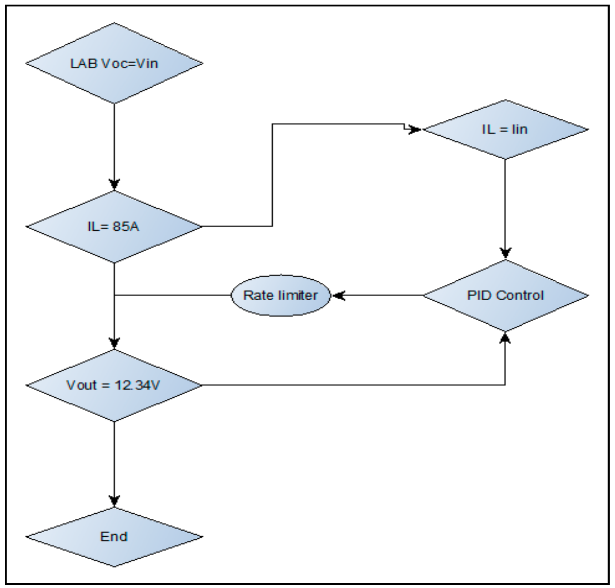
The LAB boost DC/DC converter is represented by a flow diagram as shown below in
Figure 2. The converter is controlled based on power width modulation (PWM) of saw tooth signal. The battery voltage is controlled using a PID, which regulates the battery SOC. The saw tooth signal generator of a power width modulator is generated from the specialized technology in control and measurement library under the generator of different signals. The PWM generates a saw tooth waveform, with peak values between +1 and −1. The output of the generator is specified as a time value pair for the simulation. Consequently, the PID controller is implemented as a continuous time domain. The derivative of this controller is set to zero and connected in parallel.
Figure 2 below illustrates the control strategy of the LAB’s boost DC/DC converter for ensuring a stable DC output voltage as compared with the reference PWM signal value. Also,
Figure 3 below shows that the initial conditions for this controller are set to execute from external variables, have a zero crossing detection functionality, and have a compensation that is represented by Equation (4). The output of the PID controller is limited to an upper and lower limit of ±1 and treats it as a gain during linearization by the saturation block. The battery characteristics are shown in
Figure 4.
where
is the compensation of the PID control.
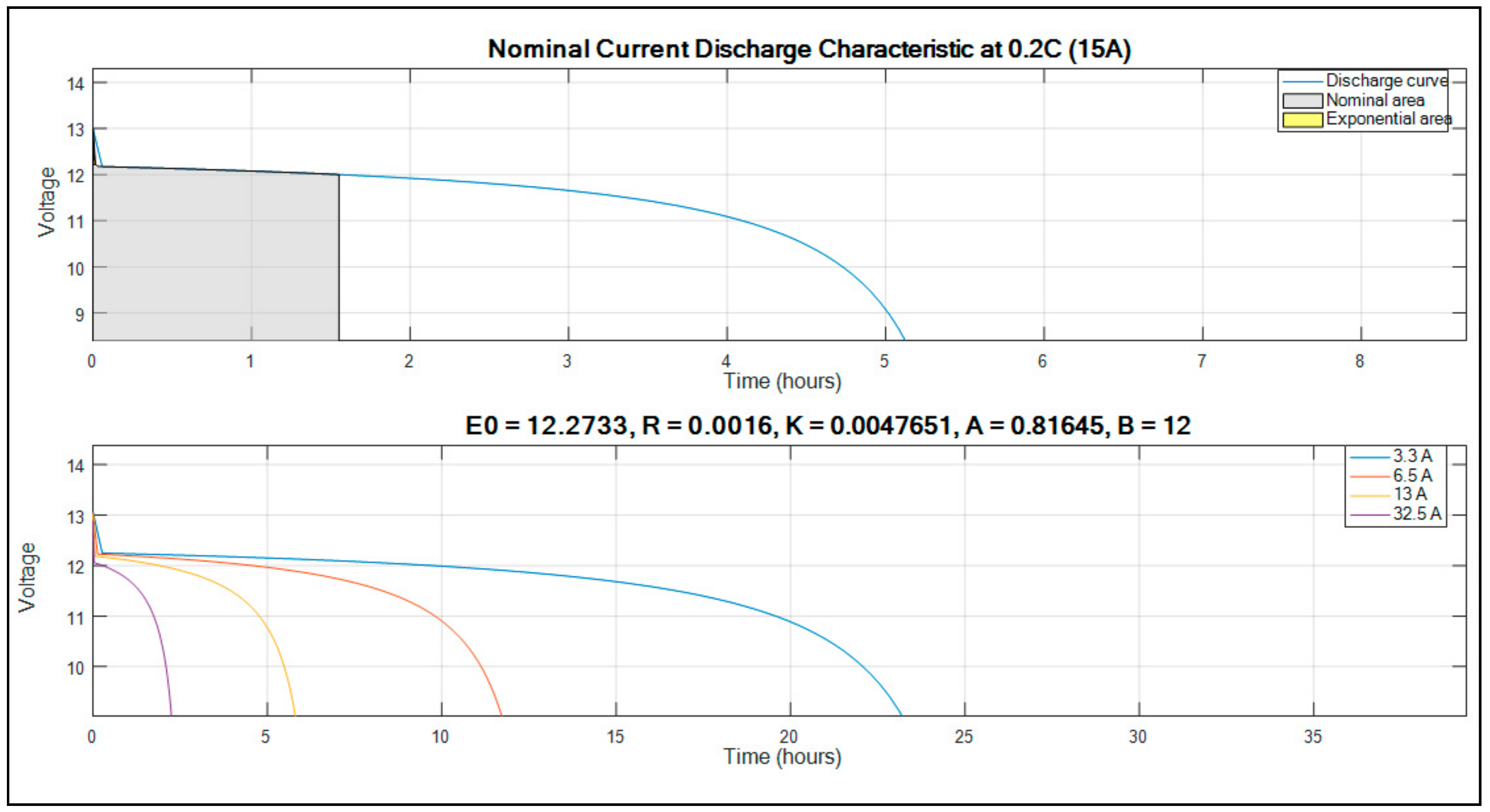
The selected battery characteristics are shown in the plotted graph of
Figure 3 below.
The graph showing the normal current discharge characteristics indicate that for this particular selected battery, it takes 5.2 h to reach a voltage of 0 V (SOC = 0%) if it is discharged at 0.2 C (15 A). The C-rate is defined as the Ampere or milli-ampere rate, which is numerically equal to the capacity rating of the cell and represented in Ah or mAh. The battery operates under normal conditions between 0 and 1.5 h of the time. Moreover, the graph showing several constants indicates that initially, the battery is at 100% SOC, and if it is discharged, it is discharged at a different current. Also, the graph indicates the requirement for changing the battery if the LAB is defective (operating conditions factors). The assumed current values are indicated on the legend of the graph. The selected battery has the following parameters:
Open circuit voltage of 12.2733 V.
Internal Resistance of 0.0016 Ω.
Performance factors K of 0.0047651, A of 0.81645, and B of 12.
This indicates that the battery lasts for 24 h if it is discharged at 3.3 A, which is the lowest in the analysis carried out.
The battery was tested at a nominal constant discharge current of 15 A (0.2 C) for 8 h under a normal operating temperature of ±25 °C. The voltage in time domain was recorded and the results were plotted as illustrated in
Figure 3 (top graph). Consequently, different discharge current of 32.5 A, 13 A, 6.5 A, and 3.5 A were applied in order to evaluate the LAB characteristics, which included open circuit voltage; internal resistance; and
K,
A, and
B factors, as illustrated in
Figure 3 above (bottom graph).
The open circuit voltage is measured and is found to be 12.2733 V, as indicated above in
Figure 3.
The charging and discharging cycle methodology approach considered for this typical LAB is constant-current-constant-voltage (CCCV) charging. Although overcharge is of great concern for this methodology approach, it can easily be controlled, unlike in constant voltage charging. Under the constant voltage charging, undercharging is of primary concern with these algorithms, and it is difficult to maneuver within the problem.
2.2. Supercapacitor
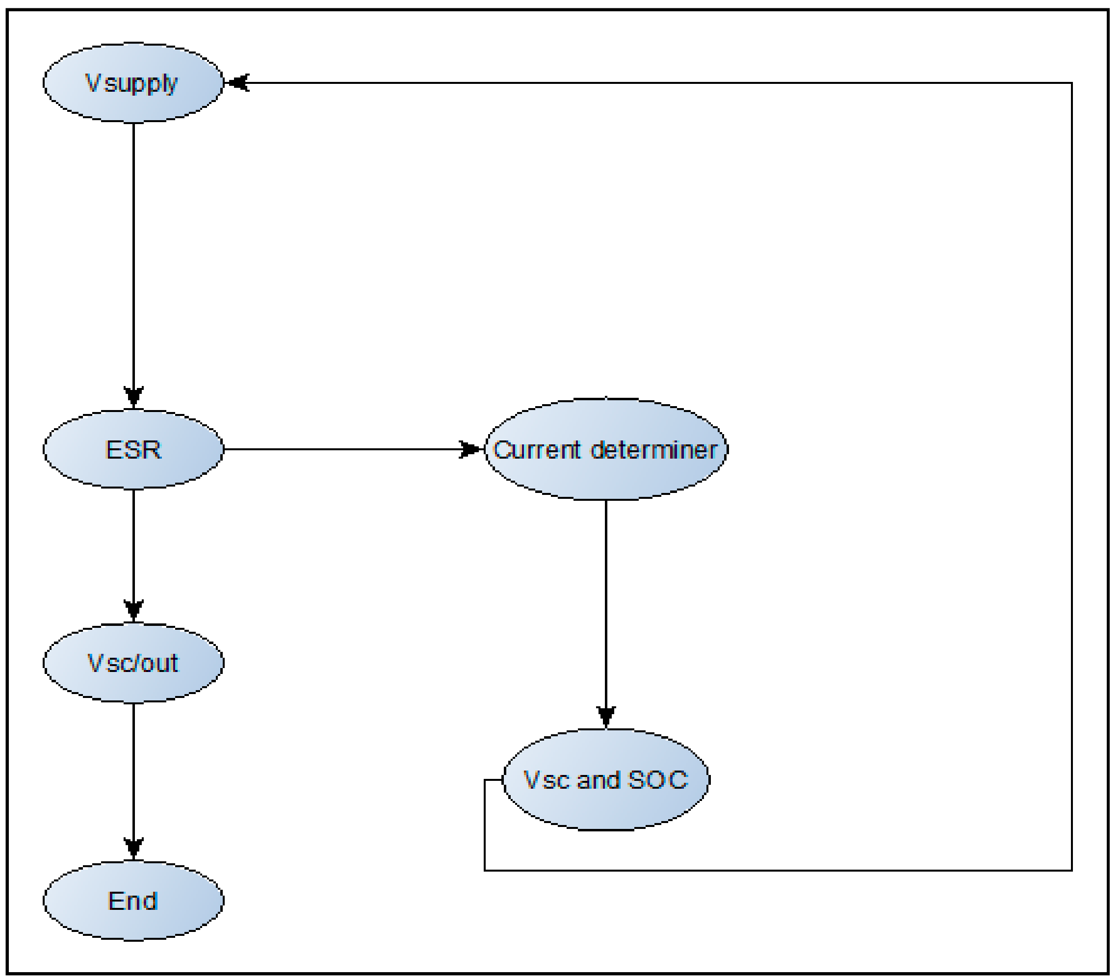
The supercapacitor used in the study is an electro double layer capacitor (EDLC) and is modelled such that it consists of similar output to that of the LAB, which consists of the terminal voltage, current, and the SOC. The supercapacitor model, the buck-boost DC/DC converter with control, is signified by a flow diagram as shown in
Figure 4 and
Figure 5 below. The supercapacitor discharge characteristics are also shown. The outputs of the supercapacitor are determined according to the following formulae:
The supercapacitor model demonstration shown in
Figure 4 is modelled using an equivalent circuit model as described in the works of [
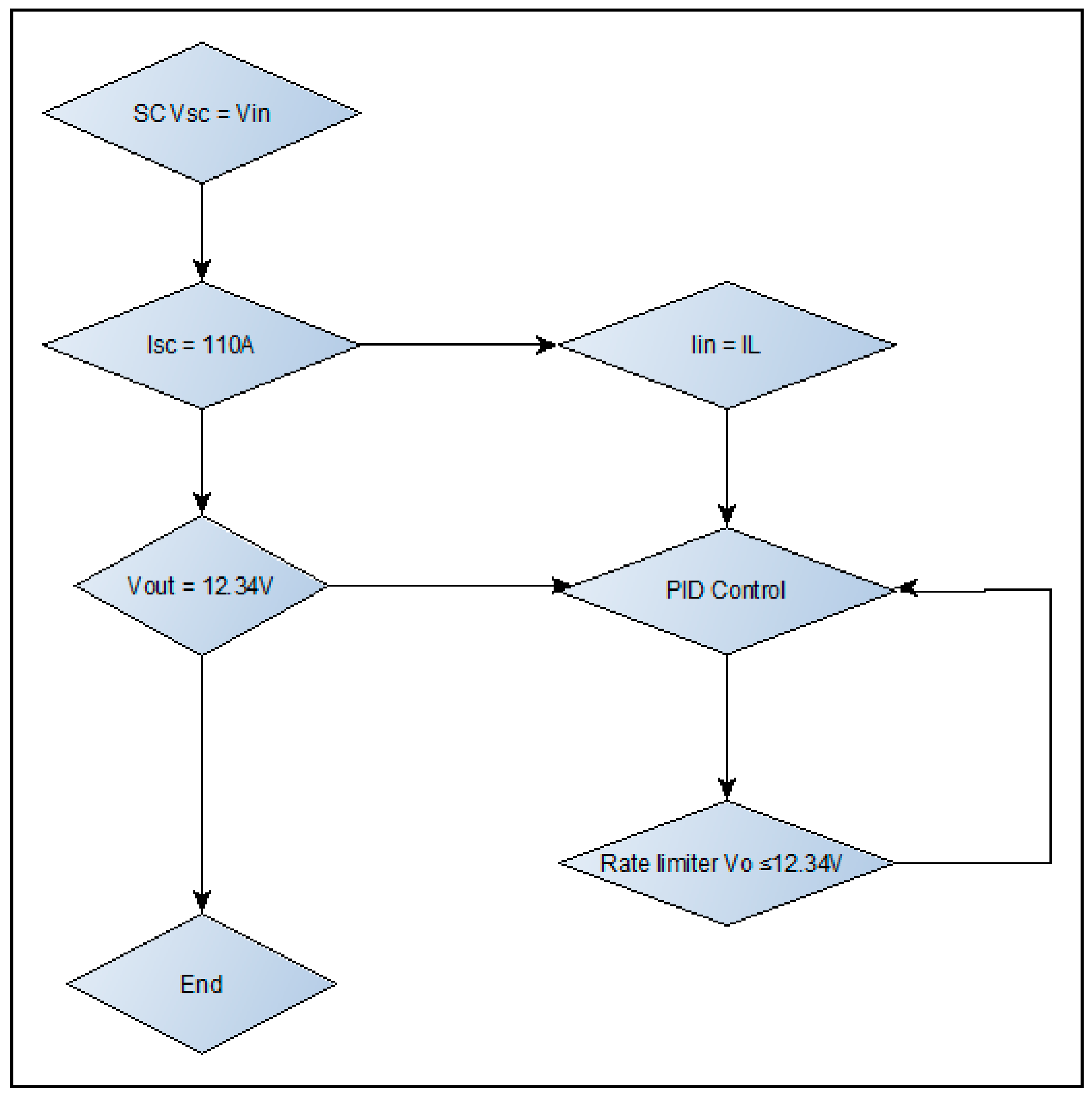
24]. The voltage of the supercapacitor is obtained using a controlled voltage source, which is connected to the continuous model for derivation of the supercapacitor’s SOC and current. The equivalent DC series resistance is assumed to be ideal. The continuous model developed for determining the supercapacitor’s SOC and current includes the summation block for connecting the output of the multiplier and the self-discharge model characteristics, thus integrating the output of the summation added to the initial charge of the supercapacitor (which reflects the formulation of SOC and current). The control strategy of the supercapacitor buck-boost DC/DC converter is described with a flow diagram in
Figure 5 below, which complements the Simulink model signified by a flow diagram shown in
Figure 6.
The buck-boost converter developed for the supercapacitor shown in
Figure 6 consists of two ideal insulated gate bipolar transistors (IGBTs) to control the current flowing to and from the DC bus. The switching mechanism of these switches is assumed to be ideal. The PID controller of the converter controls the current and the reference current to the supercapacitor. The PID operates in continuous mode and the developed form operates in parallel; it also has in internal source and uses the similar equation of compensation as described in Equation (4). The output of the PID controller is limited to ±1 by the saturation block compared with the PWM signal to be the same as or less than the limited value. The converter is developed to have bi-directional power flow (current) to absorb and provide high transient currents for acceleration and regenerative braking purposes.
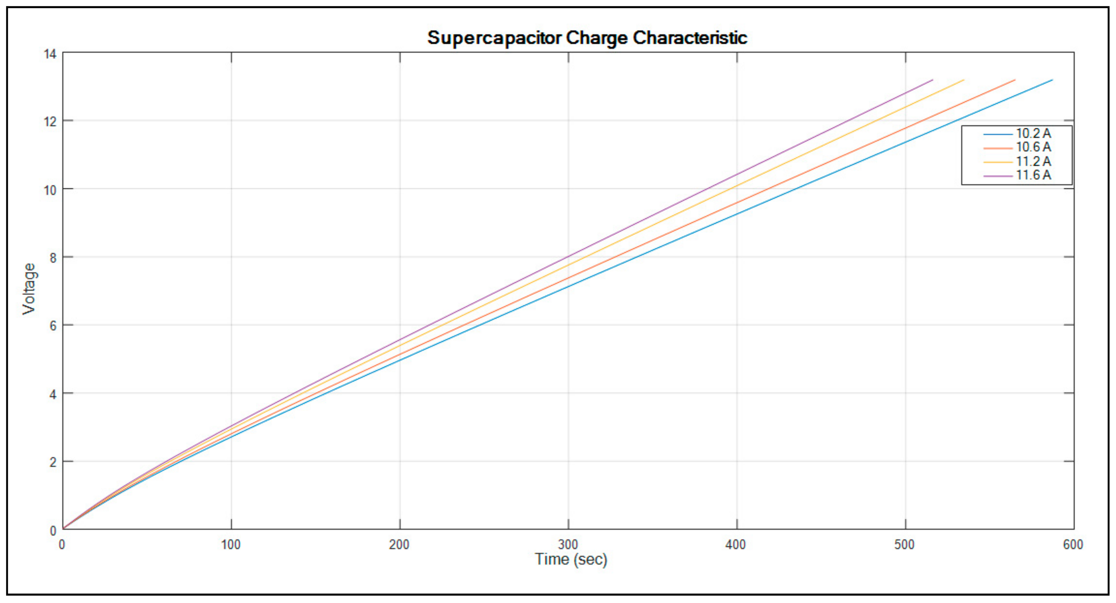
The graph showing the supercapacitor characteristics is shown in
Figure 7.
Figure 7 shows the supercapacitor voltage versus time, which indicates the supercapacitor charge characteristics. The graph indicates the current size used to charge the supercapacitor and will determine the time it will take to reach 100% SOC. The higher the current, the shorter the time it takes to fully charge the supercapacitor. In order to charge this particular supercapacitor in less than 520 s, it needs a current of 11.6 A or higher.
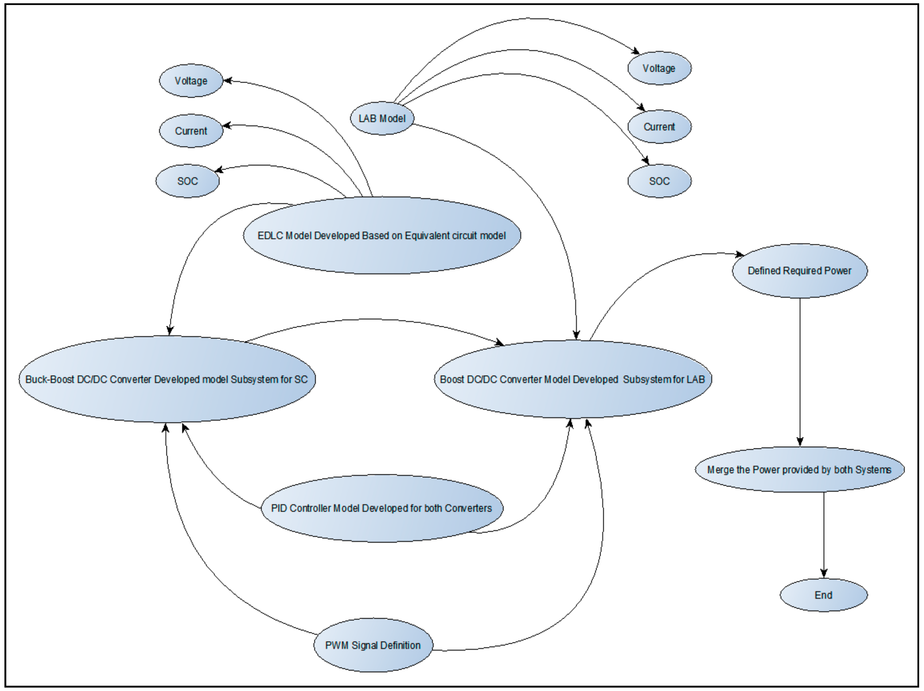
The simulation procedure of the modelled system is shown by the flow diagram in
Figure 8 below.
As shown in
Figure 8, the LAB and the EDLC supercapacitor are connected to their individual DC/DC converter. These converters are then connected in parallel to produce similar output. The output power produced by both the supercapacitor and LAB is compared and merged to the defined required power of a typical transport vehicle, as previously mentioned. Both the power converters consist of an individual PID controller for reliable control of individual energy storage systems in order to control the input and output parameters. Moreover, a similar PWM signal generator is connected to each converter. The signal generator’s function is to gate the IGBT switches for quality control and operation of the converters. The voltage output of the converters is compared with the vehicle DC bus voltage. Consequently, the system evaluates the EDLC terminal voltage, current, and SOC. The LAB’s terminal voltage, current, and SOC are also monitored during the simulation. The simulation is debugged and ran for a period of 350 s, because the computer memory was not enough to simulate for a period more than 350 s. Despite the computer memory, the simulation took more than 3 h to complete. The unprocessed simulation results are obtained and saved in a MATLAB format known as workspace for further processing.
3. Results and Discussion
The simulation of the results was performed using MATLAB/Simulink on a Lenovo Laptop computer with 6 GB Random Access Memory (RAM) with a 64-bit operating system. Hence, in order to ensure that the battery and supercapacitor hybrid system operates satisfactorily, a typical hybrid electric vehicle was used, which is equipped with a 2 kW motor. The required current for the typical hybrid electric vehicle is compared with current produced by the LAB and supercapacitor. Consequently, the LAB’s SOC and voltage are kept within 90–96% and 12 V, respectively. Moreover, the SOC of the LAB and supercapacitor is also evaluated in this simulation study.
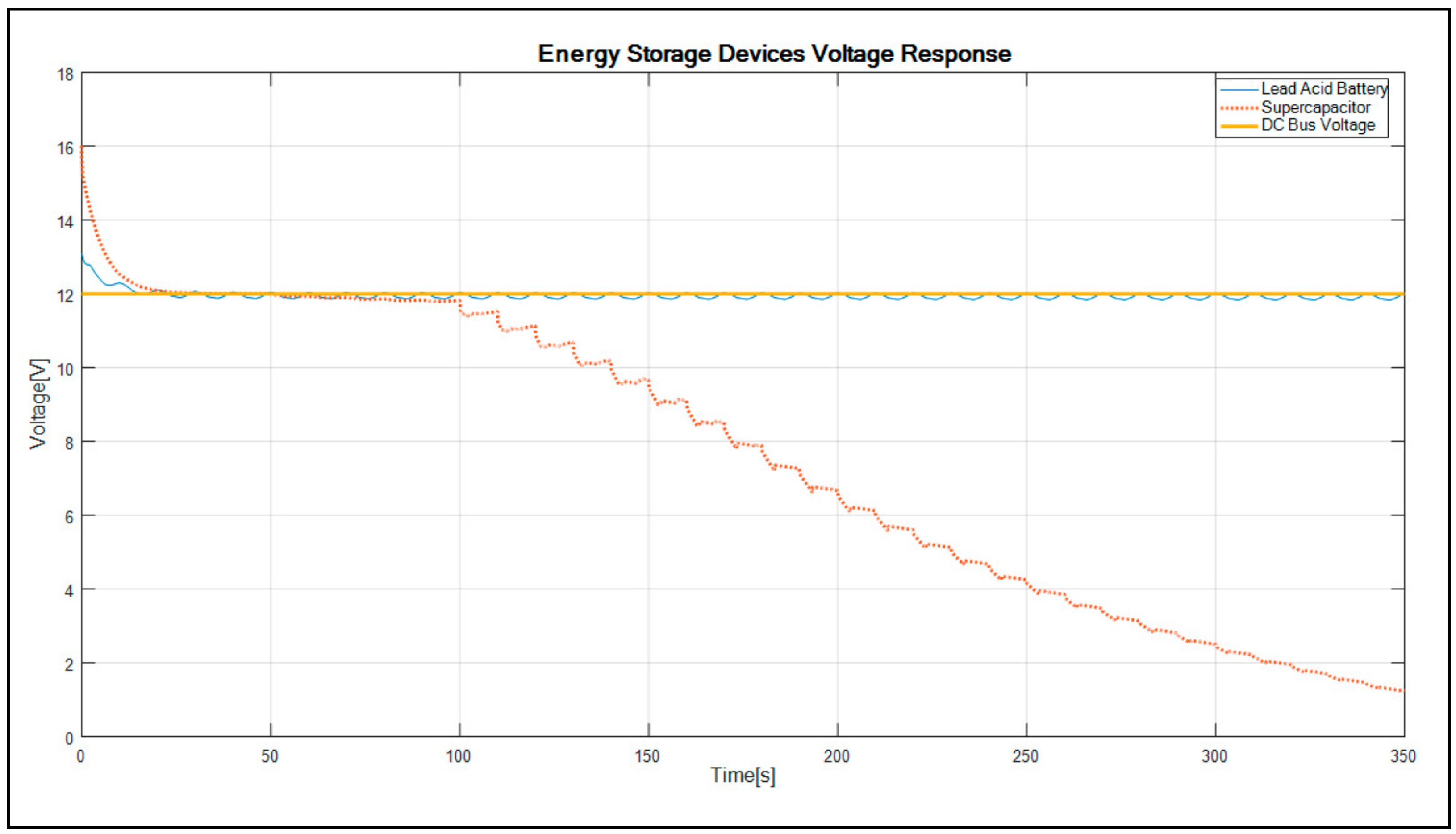
The graph showing the voltage versus time of the LAB and supercapacitor is plotted in
Figure 9.
As shown in
Figure 9, the lead acid battery and supercapacitor show a decreasing dynamic voltage response between 0 s and 30 s when the current is supplied to the DC bus. Thereafter, the voltage of the LAB becomes constant for the duration of the simulation, whereas the supercapacitor voltage continues to decrease close to zero after 100 s of the simulation. The voltage of the LAB resonates at 12 V, which describes better balance battery voltage as described in the work of [
25]. When compared with the supercapacitor’s voltage, the results indicate the dynamic descending response at the beginning of the simulation, whereby after 30 s, the supercapacitor’s voltage merged with the LAB’s voltage. As a result of the supercapacitor being unable to hold a charge for a long duration, it is clear from the results that the voltage reached less than 4 V from 15.5 V. There is 1.6% change in the LAB’s voltage, which offers better system performance as compared with the illustrated topology in the literature [
21,
26,
27].
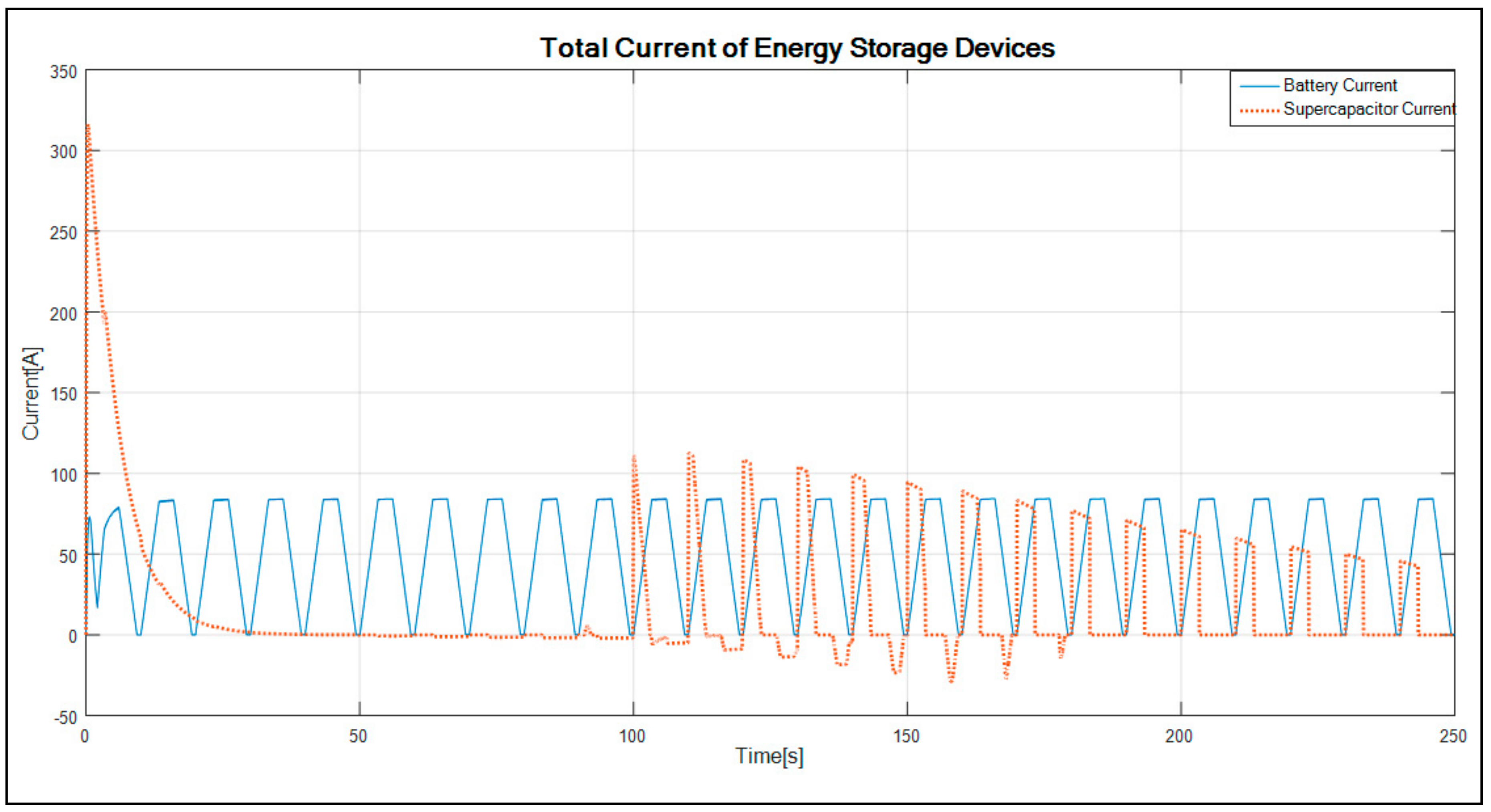
The plotted graph showing the delivered average current by the LAB and supercapacitor is shown in
Figure 10.
As shown in
Figure 10, the supercapacitor shows a dynamic decrease response of current between 0 s and 35 s of the simulation; thereafter, the current is zero until 100 s of the simulation. Hence, the supercapacitor begins charging for the remaining duration of the simulation and reaches the maximum of 110 A from 13.4 A. Consequently, the LAB supplies a more stable current of about 55 A from the initial point to the end of the simulation results. The current delivery from both energy storage devices to the DC bus is close to 165 A. The battery indicates a stable current delivery of approximately 98 A and that of the supercapacitor fluctuated and reached a maximum of 110 A over the simulation period. The fluctuation is caused by charging/discharging of the device. For a 2 kW motor, both the devices can meet the motor current demand at a DC bus voltage of 12 V. There is a better stability of current provided by the battery, making this topology a better approach system compared with the current variables provided to the described topology results in the literature [
22,
28,
29].
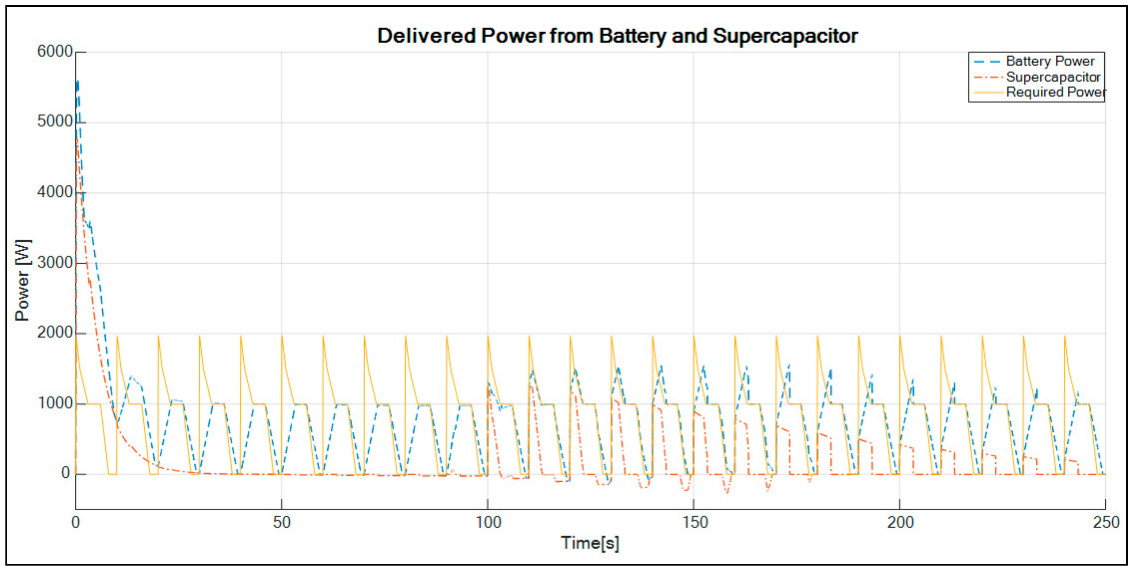
The graph describing the power delivered by the LAB and supercapacitor compared with the typical required vehicle power versus time is shown in
Figure 11.
As shown in
Figure 11, there is a significant dynamic decrease response of the power delivered to the TVs within the first 25 s of the simulation. This is because of the high required starting power for a typical hybrid system, which is more than twice the required power. The battery alone is incapable of delivering the required power of a typical hybrid transport vehicle. With the addition of the supercapacitor, the results show that the LAB and supercapacitor can be connected and deliver the required power to the TV. The behavior of the LAB and supercapacitor demonstrating a dynamic response of high power at the beginning can indicate the energy storage device initial SOC and can be used to satisfy the hybrid TV demand. It can be seen that in the event where the supercapacitor is unable to supply the power to the TV, the battery is providing the average power required. There is 9% extra power delivered by the system, making it a better hybrid topology compared with the topologies illustrated in the works of [
30,
31].
The results of the simulation topology are summarized in
Table 2 below.
As described in
Table 2 above, the results indicate that the battery SOC and voltage are kept within the statistical limits of 97% and 12 V, respectively. Keeping the battery voltage and SOC at this limits enhances the battery lifespan. Therefore, the topology ensures that the battery is not over/under charged at any circumstances of the simulation.
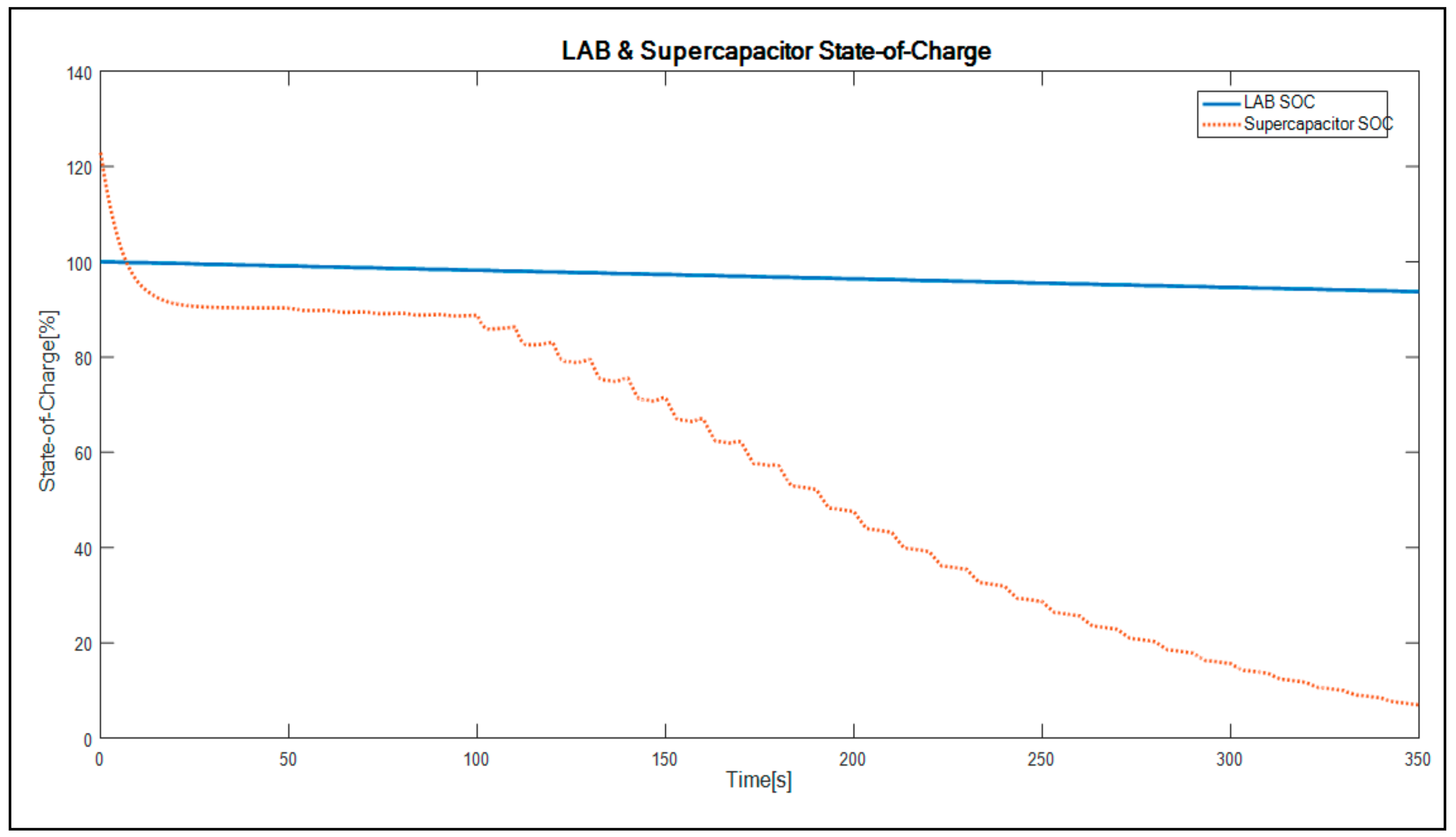
The plotted graph showing the battery and supercapacitor SOC versus time is shown in
Figure 12.
As shown in
Figure 12, the lead acid battery SOC reduces by up to 95% or less, and keeps resonating at 96% for the duration of the simulation. This stipulates that the battery is kept at a good SOC limit, as does not reduce to less than 50%. Consequently, the supercapacitor SOC is stable at between 95% and 100% for 100 s of the simulation study and thereafter, begins to drop as it discharges. Therefore, the supercapacitor discharges all the energy and recharges for the next cycle.
The converter algorithm of LAB keeps the battery state-of-charge at 96%. This ensures that the battery is not deeply discharged during operation. The voltage is kept as constant as possible at 12 V. This ensures that the battery is not stressed and allows a minimum current to flow through the battery for the charging algorithm. When compared with the supercapacitor, it allows high currents to flow through it. The supercapacitor characteristic of having more than 1000 cycles for charge/discharge allows it to save the battery for deep cycles, hence allowing the battery to have endured an enhanced lifespan.
Based on the results, the proposed hybrid system provides better battery terminal voltage stability for a prolonged period, as well as the battery SOC. Although the battery SOC is kept high enough, this causes the battery to have a low charge acceptance. Hence, all the excess energy during regenerative braking can be stored by the supercapacitor. The system is easier to implement than the complex control methodology used in the described references. The system enhances battery lifespan significantly by controlling the battery terminal voltage and SOC, thus keeping it at high statistical limits of 12 V and 96%, respectively.


