Analysis, Design, and Implementation of Improved LLC Resonant Transformer for Efficiency Enhancement


1
College of Electrical and Information Engineering, Hunan University, Changsha 410082, China
2
College of Electrical Information, Hunan Institute of Engineering, Xiangtan 411100, China
3
College of Physical and Electrical Engineering, Wenzhou University, Wenzhou 325000, China
*
Author to whom correspondence should be addressed.
Energies 2018, 11(12), 3288; https://doi.org/10.3390/en11123288
Submission received: 9 November 2018
/
Revised: 19 November 2018
/
Accepted: 22 November 2018
/
Published: 25 November 2018
(This article belongs to the Special Issue Energy Efficiency in Electric Motors, Drives, Power Converters and Related Systems)
Abstract
:In battery charging applications, the charger changes its output voltage in a wide range during the charging process. This makes the design of LLC converters difficult to be optimized between the efficiency and the gain range. In this paper, an improved resonant transformer is presented for LLC resonant converter charger to improve the gain adjustment and charger efficiency. The resonant inductance and magnetizing inductance are integrated in the designed LLC transformer, and the magnetizing inductance can be adjusted dynamically with the change of output voltage and load, which is realized by a switch-controlled inductor (SCI) parallel to the secondary winding of transformer. The proposed transformer has 22.4% reduction in losses under full load conditions compared to conventional solutions. Moreover, the conduction loss and switching loss of LLC resonant tank are reduced by dynamically adjusting the magnetizing inductance, which improves the comprehensive efficiency of the whole charging process. The proposed transformer design is verified on a 720 W prototype.
1. Introduction
LLC resonant converter has been widely used in electric vehicle battery chargers, flat panel television (TV), and photovoltaic (PV) system due to its high-power density and high conversion efficiency [1,2,3,4]. For now, it has become one of the most concerned DC/DC converters.
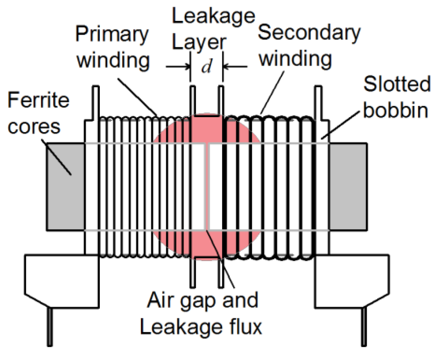
In constant output voltage applications, LLC resonant converter can achieve high efficiency. However, there are many challenges for LLC resonant converter in the charger applications which requires a wide output voltage adjustment range [5]. It requires a small magnetizing inductance to obtain a wide output voltage adjustment range, but it can lead to increased conduction loss and switching loss as well as efficiency reduction [6]. The magnetizing inductance is usually integrated in LLC resonant transformer. The usual structure of magnetic integrated LLC transformer is as shown in Figure 1, the leakage layer is set between the primary winding and secondary winding. The required resonant inductance is obtained by using stray flux and the magnetizing inductance is achieved by inserting an appropriate air-gap in the magnetic circuit [7,8]. The transformer with that structure has high integration and low cost and has been widely used in converters with power level from dozens to hundreds of watts.
As the core device of LLC resonant converter, the transformer plays a critical role in converter’s efficiency, volume, power density, and reliability. However, the whole loss of the LLC resonant transformer has a much higher percentage than that of phase-shift full-bridge transformer in the same power [9]. One of the main reasons is that the air gap in the magnetic core of LLC resonant transformer causes fringing effect, leading to an increase in the equivalent resistance of windings near the air gap, and the transformer inner temperature rise distributed imbalance. The other reason is that the small magnetizing inductance leads to increased conduction loss and switching loss of the LLC resonant converter, so the light-load efficiency is lower.
In order to improve the efficiency of LLC transformer, different improvement designs are proposed. In [10], a novel shape magnetic core is used to achieve the integration of two LLC transformers. In [11], a magneto plated wire is used to effectively decrease the winding loss caused by the proximity effect when working in high frequency. In [12], the integration of resonant inductance required is achieved by inserting a layer of flexible magnetic material between the primary and secondary windings. The designs proposed by [10,11,12] have high integration, but without regard for the fringing effect, so they are more suitable for low power applications. In [13], the copper loss of the Litz wire caused by the air gap is analyzed, and the influence of the fringing effect is weakened by using multiple small air gaps in series, but this increases the cost and difficulty of transformer production. In [7], a design method of LLC resonant transformer is presented, and the current density in the conductor near the air gap is simulated. In [14], the optimal design method of the transformer in conventional LLC resonant converter is extended to the design and application of flat panel transformer, and a complete design scheme and a detailed application method are given. In [7,14], the fringing effect is mentioned, but the influence of the effect is not analyzed and the solution is not given. In [15], the relationship between the temperature rise and the switch frequency as well as the winding number of the LLC resonant transformer are discussed, and a combination of two smaller transformers is used instead of one larger transformer to reduce the temperature rise. Matrix transformer is used to achieve a higher output power in [16]. However, with the increase of power, the matrix transformer which consists of too many transformers will lead the system more complex. In [17,18], to reduce the influence of the fringing effect, the distance between the winding and the air gap is increased by making changes of the winding structure, which leads to the increase in difficulty of processing windings.
To improve the light-load efficiency, the transformers in [19,20] are designed with variable magnetizing inductance. In [19], by using utilizing a step-gap in the core column, a larger magnetizing inductance is obtained at light load, and it decreases at heavy load, but the variety of magnetizing inductance is non-linear and uncontrollable. In [20], a bidirectional power switch is used to achieve the parallel operation of two transformers. When under heavy load, the switch turn-on, two transformers primary side work in parallel, the magnetizing inductance of resonant tank is small, and can satisfy the gain demand required in the initial stage of charging. When under light load, the switch turns off, only one transformer works, the magnetizing inductance of resonant tank is large, and the conduction loss and switching loss of primary side decrease. However, the resonant inductance cannot be integrated into the transformer, the magnetizing inductance can only be changed between two fixed values, and when under light load, only one transformer works and the other is vacant.
Aiming to address the design problems of the conventional LLC transformer caused by the large influence of the fringing effect and the unchangeable magnetizing inductance, this paper presents a design for the integrated LLC resonant transformer. The magnetizing inductance does not need to be obtained by inserting air gap, so the fringing effect of the transformer is small. Moreover, the magnetizing inductance can be dynamically adjusted by a SCI parallel to the secondary winding of the transformer. This can not only improve the efficiency and the temperature rise of the transformer but also optimize the comprehensive efficiency of the LLC resonant converter during the whole charging process.
This paper includes following aspects. Section 2 analyzes the conventional integrated LLC resonant transformer. Section 3 presents the proposed design scheme, analysis of magnetic flux in the transformer core and the application circuit. Section 4 gives the calculation formula and design procedure of the transformer. Section 5 shows the experimental results of a 720 W LLC resonant converter. The conclusion is given in the last section.
2. Analysis of Conventional LLC Transformer
In high-power applications, the fringing effect near the air gap leads to a significant increase in the current density of the windings near the air gap, resulting in an apparent increase in the partial temperature rise and copper loss of the transformer [7]. To analyze the influence of fringing effect, finite element analysis (FEA) simulation is carried out by using Maxwell software. Figure 2 illustrates the simulation of fringing effect at 100 kHz. It can be seen the current density of the copper conductor near the air gap is about 70% higher than that away from the air gap, so the copper loss of this part is significantly increased. The increased copper loss results in the conspicuous regional temperature rise near the air gap. The simulation also shows that the fringing effect has a significant impact near the air gap, and the affected range increases with the increase of transformer power from the center of the air gap.
After the winding turns and air gap size of the transformer are determined, the transformer magnetizing inductance is a fixed value. Choosing small magnetizing inductance to obtain sufficient output voltage gain will result in increased conduction loss and switching loss of the LLC resonant converter.
The simulation results show that the induced magnetic flux increases in pace with the increase of the transformer power and input voltage, the area influenced by the air gap expand accordingly. In order to reduce the fringing effect, it is needed to increase distance d of leakage layer, as shown in Figure 1. However, the increasing d causes the available area of the core window decrease, under the same diameter and turns, the layer p of transformer winding is increase. According to the Dowell’s formula as below, this effect can lead to a significant increase in proximity loss.
where, p is the number of transformer windings layers, Δ is the ratio of the winding layer thickness d of the skin depth .
To integrate the resonant inductance into the transformer, the primary winding and the secondary winding cannot use ‘sandwich’ method, which is used in full-bridge phase-shifting transformer to decrease the proximity loss. Therefore, at high frequency condition, use Litz wire to decrease the impact of the proximity effect and the skin effect.
In summary, the fringing effect, proximity effect, and the increase of the conduction loss and switching loss caused by small magnetizing inductance are main factors affect the transformer efficiency.
3. Analysis of Improved LLC Resonant Transformer
In order to promote the efficiency, an improved LLC transformer design is presented.
3.1. Main Structure
The structure of proposed LLC resonant transformer is shown in Figure 3, which has the following characteristics. (1) The skeleton adopts double groove structure, thus primary winding and secondary winding are wound respectively in two grooves. Therefore, the resonant inductance is still integrated in the transformer. (2) The air gap is not inserted in the magnetic circuit, so there is nearly no leakage flux, the intensive windings in the transformer is almost not affected by the fringing effect. (3) The thickness d of the middle leakage layer can be small, which does not occupy the space of the windings and improves the utilization rate of the core window, reducing the proximity effect.
The fringing effect simulations comparison is shown in Figure 4. It can be seen that the conductor current density near the air gap of the proposed transformer is greatly reduced, and the conduction loss is effectively decreased, so the internal temperature rise can be improved.
However, the proposed transformer almost has no air gap, and the equivalent magnetic permeability of the magnetic core is large. Hence, its magnetizing inductance is much larger than that of conventional LLC transformer with air gap, which cannot satisfy the LLC resonant tank demand. For this reason, a SCI is parallel to the secondary winding to achieve the magnetizing inductance adjustment, as shown in Figure 5, Co is the output filter capacitor, and RL is the load.
3.2. Switch Controlled Inductor (SCI)
The SCI in Figure 5 adopts series type [21], and its circuit structure and working waveforms are shown in Figure 6. The SCI consists of linear inductance La and two control switches Ta and Tb. The voltage added to the both sides of SCI is the transformer secondary winding voltage close to square wave. VTa and VTb are the drive signal of switch devices Ta and Tb respectively, and their frequencies are equal to the operating frequency of the LLC resonant converter. The current flowing through the SCI is . is the phase angle of the switch drive signal. The working principle of SCI in a switch period is analyzed as follows.
At , when the secondary winding voltage is positive polarity and Ta is turn-off, the inductor current flow through SCI is zero. At , the drive signal makes Ta turning on and Tb turning off, and increases linearly from zero. Therefore, Ta turns on at zero current and Tb turn off at zero current. At , when the polar of reverses, the inductor current reaches a maximum and then begins to decrease linearly. At , the inductor current decreases to zero. Because of the reverse blocking of Tb, remains zero until . Therefore, Ta realizes zero current turn-off and Tb realizes zero current turn-on. The opposite direction is the same. Since the conduction resistance of Ta and Tb is very small, the switching loss and conduction loss of switch devices Ta and Tb are relatively small.
The equivalent inductance of SCI can be obtained from [22] as Equation (2)
According to Equation (2), when the phase angle of switch drive signal ranges between and , the equivalent switch-controlled inductance ranges between La and . The relationship curve between inductance ratio and the phase angle of switch drive signal is shown in Figure 7. It can be found the circuit shown in Figure 5 can be equivalent to an inductance which can be adjusted from La to .
3.3. Equivalent Circuit of Resonant Tank and Magnetic Field Analysis
The equivalent circuit of LLC resonant tank for secondary winding parallel SCI is shown in Figure 8. where Cr is the resonant capacitance, Lr is the resonant inductance and Lm-ini is the large magnetizing inductance integrated in transformer, as shown in Equation (3).
where is the equivalent magnetic permeability of the magnetic circuit approximately equal to the relative permeability of the core material . is the turns of primary winding, is the cross-section area of the magnetic core, is the magnetic circuit length. Since , the value of is large as result of the large relative permeability of the core material.
Setting a is the ratio of the transformer, and is the primary equivalent inductance reflected by the SCI. Re is the equivalent load impedance, and is the load resistance. The magnetizing inductance in the resonant tank can be expressed as Equation (4).
Due to the adjusted value of driven by , so the inductance in Equation (4) can be represented as an adjustable inductance. Therefore, the equivalent magnetizing inductance Lm-eq can also be adjusted by changing .
As shown in Figure 8, when the resonant tank is transferring energy to secondary side, the resonant frequency is .
Otherwise, the magnetizing inductance Lm-eq participates in resonant, and the resonant frequency is Equation (7).
Inner magnetic flux analysis of the transformer is shown in Figure 9. The primary side is on the left, and the secondary side is on the right. The flux and in the magnetic core established respectively by the primary resonant current ip and the secondary current is cancel each other. Meanwhile, the flux and in the magnetic core established respectively by the magnetizing current iLm-eq and the SCI current iAB cancel each other. It follows that, the transformer does not store energy, and the inductive energy storage required by LLC half-bridge switch for zero voltage switching (ZVS) is completed by SCI.
3.4. LLC Resonant Converter Charger Application
The application of the proposed transformer in LLC resonant converter charger is shown in Figure 10, and the secondary side adopts a full-bridge rectifier. The resonant tank consists of Cr, Lr, and Lm-eq.
The ratio of the equivalent magnetizing inductance to resonant inductance is defined as Equation (8).
In Equation (9), Q is the quality factor. Under constant Lr, Cr, and a, Q is only related to load. Under the same load (Q value), the voltage gain curves with different k are shown in Figure 11. The horizontal axis is the normalized frequency, which is the ratio of working frequency fs to resonant frequency fr, and the vertical axis is DC voltage gain. It can be seen that in the same frequency range, a resonant tank with smaller k can get a larger output voltage regulating range. Moreover, under the condition of fixed resonant inductance Lr, the proposed transformer can regulate Lm-eq to adjust k, so that it can dynamically adjust the voltage gain of LLC resonant converter in the charging process according to the corresponding demand.
Furthermore, the simplified typical battery charging curve is shown in Figure 12. The charging process can be divided to three stages: constant current charging, constant power charging, and constant voltage charging. The output power becomes very small at the charging end.
At the initial stage of charging, the charger current Io is large, and the output voltage Vo is relatively small. At the latter stage of charging, the output voltage Vo is relatively high and the output current Io is small. According to Equation (10), the Q value should be large at the initial stage of charging. With the charging process carrying on, the Q value decreases. Figure 13 gives several gain curves of k value in the charging process. The shaded area (ZVS region) in Figure 13 is the work areas of LLC resonant converter. Usually, the operating frequency of LLC resonant converter is set as the resonant frequency with the maximum output power (point A in Figure 12), since the LLC converter can get highest efficiency [22].
Therefore, the operating frequency of the constant current charging stage in Figure 12 is located at the right of the resonant frequency (fn = 1) in Figure 13. The primary switching device of LLC resonant converter works in the ZVS conduction state, but the turn-off loss increases with the increase of frequency and the secondary rectifier diode loses ZCS characteristic. Therefore, in this area, the operating frequency can be set as close as possible to the resonant frequency. As shown in Figure 13, the curve corresponding to a smaller K value is closer to the resonant frequency point (the frequency range is smaller with same gain range). When charging process enters constant power stage, the LLC resonant converter works at the left of the resonant frequency point. The primary switch of LLC resonant converter can realize ZVS conduction, and the secondary rectifier diode can realize ZCS turn-off, which can achieve better efficiency. With the decrease of operating frequency, the smaller K value leads to the increased resonant tank magnetizing current, conduction loss as well as turn-off loss. Especially, when at light load, the proportion of conduction loss in the whole loss increases and reduces overall efficiency. Therefore, with the decrease of output power and the increase of output voltage, the magnetizing inductance should gradually increase (k value gradually increases). In the conventional scheme, the K value is constant after the magnetizing inductance is selected. However, the proposed transformer can make the LLC resonant converter change its equivalent magnetizing inductance according to load and output voltage during the whole charging process, so that the gain characteristic, circulation loss, and switching loss of LLC resonant tank can be optimized via programming.
4. Design Methodology
4.1. Electrical Design Considerations
A: Selection of magnetizing inductance
The maximum magnetizing inductance to realize ZVS under idle condition is Lm1, and the maximum value to ensure the maximum gain at the lowest frequency is Lm2. The final value of the magnetizing inductance should satisfy the above two requirements at the same time. Hence, the smaller one between Lm1 and Lm2 can be chosen. If Lm1 is greater than Lm2, the dead time tdead should be appropriately reduced [23], as shown in Equation (11).
where is the maximum DC gain, and is the total equivalent capacitance of the H bridge.
B: Selection of minimum resonant inductance
The minimum resonant inductance should limit the maximum output current under short circuit when working at the highest frequency.
C: Selection of resonant capacitance
After Lr is selected, the resonant capacitance can be obtained by Equation (13).
4.2. Transformer Loss and Thermal Design Considerations
The loss of transformer includes core loss and winding loss.
A: Core loss
The core loss and core loss can be calculated by Steinmetz formula.
where Vc is the core volume, Kc is the typical value. α and β are provided by core manufacturer or obtained by loss curve.
B: Winding loss
The winding loss include DC loss and AC loss. The current through the winding can be calculated as below.
The current through the primary winding is the sum of and , and the current through secondary winding is the sum of and . The expressions of the peak current through primary winding is with the RMS value , and the peak magnetizing current are [7]
where Ts and Tr are the switching period and resonant period respectively, Vo and Io are the output voltage and output current, respectively.
By using Equation (18), the RMS value of the current though secondary winding can be obtained.
where , .
The DC copper loss is calculated as below.
The AC impedance of winding can be got from Equation (1).
C: Temperature rise consideration
The maximum loss is determined by the core thermal resistance and the permissible temperature increase.
where Rθ is the thermal resistance of the core provided by manufacturer or obtained from empirical data, hc is thermal conductivity, and At is the surface area of transformer.
4.3. Transformer Design Considerations
Under the premise of minimize core loss and winding loss, the design purpose of a transformer is to transfer energy from input side to output side by electromagnetic induction. The optimization result can be boiled down to one conclusion: iron loss is equal to copper loss [23]. The transformer design method is related to the best magnetic induction intensity and temperature rise of magnetic core and is limited by the maximum permissible power loss.
A: Core selection
The appropriate core is up to Ap value. Ap is the product of core window area Wa and core cross-section area Ac, as Equation (22).
where, is the sum of each windings rated VA values, Kv = 4.44, is the operating frequency, is the best magnetic induction intensity value, = 48.2 × 10³, is the core lamination factor, is the effective sectional area of magnetic circuit.
The best magnetic induction intensity is given by Equation (23).
where, is the thermal convection transfer coefficient with typical value 10, and , , and are dimensionless constants with the typical values = 40, = 5.6, = 10. are the material parameters, is the wire resistivity.
B: Calculation of transformer winding turns and turns ratio
The winding turns can be calculated by Equation (24).
where is the wingding terminal voltage, is the core cross-section area, is the smaller one between and . is usually smaller than at the high frequency condition.
The turns ratio can be calculated by Equation (25). where, Vd is the conduction voltage drop of the secondary rectifier diode.
C: Transformer wire diameter selection
The current density in the wire should satisfy the temperature rise requirement under the whole power loss.
The calculation of wire sectional area is Equation (27).
D: Determination of inductance La
According to Equation (2) and Figure 7, the switch-controlled inductance LSCI can be adjusted in a wide range. When α = , LSCI = La. While the k value of LLC resonant tank obtains a minimum value kmin as Equation (28) According to Equation (4).
5. Experimental Verification
5.1. Design Specification
An LLC resonant DC/DC converter with 720 W output power is designed, its input voltage is 390 VDC and output voltage is 60 VDC–96 VDC with maximum output current is 8 A. The resonant frequency is 85 kHz. According to Equation (12), the resonant inductance Lr should be greater than 44 µH and set as 50 µH. According to Equation (13), the resonant capacitance Cr is 70 nF. According to Equation (24), the transformer turns ratio a = 2:1. According to Equation (28), kmin is 3, Lmin is 1 mH and La = 44 µH.
The design requirement is shown in Table 1, the RMS value of resonant current, the peak magnetizing current and the RMS value of secondary current are calculated by Equations (15)–(18). The core window utilization factor ku is 0.55.
5.2. Transformer Parameters
The ferrite core is used for the high switch frequency. = 0.1 T is calculated by Equation (23), = 2.5 cm4 is calculated by Equation (22), the ETD44 magnetic core is chosen. The magnetic material is the N87 from EPCOS company, the parameters of this material are given in Table 2, and the parameters of core and winding are given in Table 3. The saturation flux density of this material is 0.4 T. By Equation (24), the transformer secondary turns can be calculated as Ns = 11.9 ≈ 12. The primary turns number is 24.
The current density can be obtained by Equation (26) as 344 A/cm2, and the wire sectional area of the primary winding is 0.0132 cm2 from Equation (27). Considering the wire skin effect at high frequency, the skin depth is
It is set as = 0.226 mm and the specification parameters are shown in Table 4. The DC resistance of primary winding is 120.3 µΩ/cm (20 °C).
To reduce the secondary proximity effect, the Litz wire of 0.15 mm × 110 mm is chosen. The equivalent electric conduction area is 1.95 mm2, the current density is 464 A/cm2, and the primary DC internal resistance is 89.2 µΩ/cm (20 °C).
The DC internal resistance of each winding can be obtained with temperature correction as
where Tmax is the maximum temperature.
Considering the wire skin effect at high frequency, the skin effect factor is calculated by
where, . is the radius of wire and = 0.255 mm.
The influence of the proximity effect of the secondary winding is calculated by
where, is the diameter of wire. The ratio of secondary AC resistance and DC resistance is . Power loss and the efficiency of transformer are shown in Table 5. It is worth noting the efficiency of the transformer is calculated under the condition of resonant frequency and full power.
5.3. Experimental Results
The designed transformer is applied to 720 W LLC resonant converter charger. The experimental waveforms under different operating conditions are given in Figure 14. The operating waveform of LLC resonant converter at the initial stage of constant current charging is given in Figure 14a. The output power is 608 W and the operating frequency is 98.1 kHz, which is higher than the resonant frequency. The phase-shifting angle of the SCI is α = π/2, and the current of the SCI branch is triangular wave. At this time, the magnetizing inductance of the resonant tank is small, the K value is also small, which helps reducing the switching frequency range.
Figure 14b shows the working waveform of LLC resonant converter at the constant power charging stage. The output power is 720 W and the operating frequency is 84.8 kHz, near the resonant frequency. The phase-shifting angle of the switch-controlled inductor is α ≈ 0.67π, and the magnetizing current of the transformer is relatively decreased, which reduces the conduction loss.
Figure 14c shows the working waveform of LLC resonant converter at constant voltage charging stage. The output power is 240 W, the operating frequency is 70.2 kHz, which is lower than the resonant frequency, and the output power is smaller. The phase-shifting angle of the switch-controlled inductor is α ≈ 0.79π, the magnetizing current of the transformer is decreased further and the light load efficiency is improve effectively.
The experiment results comparison of the transformer temperature after operating under a full load for 1 h is shown in Figure 15. The temperature rise of the proposed transformer is 65.2 °C. Experiments show that the transformer works in an ideal temperature rise range. In addition, the conventional transformer with air gap is applied to the same resonator circuit, the transformer retaining wall interval d is 4.3 mm, the temperature rise is measured as 83.8 °C. Moreover, the temperature rise of the secondary winding near the air-gap is the highest, which is 14.9 °C higher than the proposed transformer.
Corresponding to Figure 14, the measured loss of the proposed transformer under 100%, 80%, and 33% loads are compared with those of the conventional LLC transformer, as shown in Figure 16. Experimental results show that the proposed design scheme is more efficient to reduce the temperature rise of magnetic components.
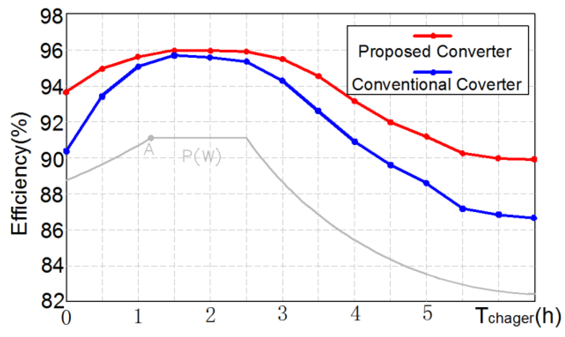
Figure 17 shows the efficiency comparison between the proposed LLC resonant converter charger and the conventional LLC resonant converter charger (k = 5) in the whole charging process. At the left of point A, the operating frequency is higher than resonant frequency. The proposed transformer magnetizing inductance can be dynamically adjusted, which not only improves the efficiency of the transformer itself, but also effectively reduces the conduction loss and switching loss of the LLC resonant converter. Hence, the comprehensive efficiency can be improved.
6. Conclusions
Aiming at the relatively low efficiency problem of the conventional integrated transformer in LLC resonant converter, a controlled magnetizing inductance resonant transformer suitable for high power LLC resonant converter is proposed. The proposed transformer mainly removes the influence of fringing effect, improving the efficiency of the transformer, and the temperature rise of transformer. The experimental results show that the temperature rise of the transformer is reduced by 14.9 °C compared with the conventional scheme. Moreover, according to the change of charging process (output voltage and equivalent load impedance changes), the magnetizing inductance of proposed transformer can be dynamically adjusted to reduce the conduction loss and switching loss of the LLC resonant converter. Therefore, the comprehensive efficiency of the whole charging process can be improved further, especially at the initial charging stage and at the charging end (light load).
Author Contributions
All the authors conceived and designed the study. Z.Z., Q.X. performed the simulation and the experiment and wrote the manuscript with guidance from Y.D., Z.Z., Q.X., Y.D. and H.Y. reviewed the manuscript and provided valuable suggestions.
Funding
This work was supported by the National Natural Science Foundation of China (NSFC) under Grant No. 51807056.
Conflicts of Interest
The authors declare no conflict of interest.
References
- Deng, J.; Mi, C.C.; Ma, R.; Li, S. Design of LLC resonant converters based on operation-mode analysis for level two PHEV battery chargers. IEEE/ASME Trans. Mechatron. 2015, 20, 1595–1606. [Google Scholar] [CrossRef]
- Demirel, I.; Erkmen, B. A Very Low-Profile Dual Output LLC Resonant Converter for LCD/LED TV Applications. IEEE Trans. Power Electron. 2014, 29, 3514–3524. [Google Scholar] [CrossRef]
- Uno, M.; Kukita, A. Two-Switch Voltage Equalizer Using an LLC Resonant Inverter and Voltage Multiplier for Partially Shaded Series-Connected Photovoltaic Modules. IEEE Trans. Ind. Appl. 2015, 51, 1587–1601. [Google Scholar] [CrossRef] [Green Version]
- Yang, B.; Lee, F.C.; Zhang, A.J.; Huang, G. LLC resonant converter for front end DC/DC conversion. In Proceedings of the Seventeenth Annual IEEE Applied Power Electronics Conference and Exposition, Dallas, TX, USA, 10–14 March 2002; pp. 1108–1112. [Google Scholar]
- Wang, H.; Li, Z. A PWM LLC Type Resonant Converter Adapted to Wide Output Range in PEV Charging Applications. IEEE Trans. Power Electron. 2018, 33, 3791–3801. [Google Scholar] [CrossRef]
- Jeong, Y.; Moon, G.W.; Kim, J.K. Analysis on half-bridge LLC resonant converter by using variable inductance for high efficiency and power density server power supply. In Proceedings of the 2017 IEEE Applied Power Electronics Conference and Exposition (APEC), Tampa, FL, USA, 26–30 March 2017; pp. 170–177. [Google Scholar]
- Zhang, J.; Hurley, W.G.; Wölfle, W.H. Gapped Transformer Design Methodology and Implementation for LLC Resonant Converters. IEEE Trans. Ind. Appl. 2016, 52, 342–350. [Google Scholar] [CrossRef]
- Saket, M.A.; Shafiei, N.; Ordonez, N. LLC Converters with Planar Transformers: Issues and Mitigation. IEEE Trans. Power Electron. 2017, 32, 4524–4542. [Google Scholar] [CrossRef]
- Watanabe, T.; Kurokawa, F. Efficiency comparison between phase shift and LLC converters as power supply for information and communication equipment. In Proceedings of the 2015 IEEE International Telecommunications Energy Conference (INTELEC), Osaka, Japan, 18–22 October 2015; pp. 1–5. [Google Scholar]
- Kim, E.S.; Kang, C.H.; Hwang, I.G.; Lee, Y.S.; Huh, D.Y. LLC Resonant Converter Using A Planar Transformer with New Core Shape. In Proceedings of the 2014 IEEE Applied Power Electronics Conference and Exposition—APEC 2014, Fort Worth, TX, USA, 16–20 March 2014; pp. 3374–3377. [Google Scholar]
- Yamamoto, T.; Bu, Y.; Mizuno, T.; Yamaguchi, Y.; Kano, T. Loss Reduction of Transformer for LLC Resonant Converter Using a Magneto plated Wire. In Proceedings of the 2016 19th International Conference on Electrical Machines and Systems (ICEMS), Chiba, Japan, 13–16 November 2016; pp. 1–6. [Google Scholar]
- Kang, B.G.; Park, C.S.; Chung, S.K. Integrated transformer using magnetic sheet for LLC resonant converter. Electron. Lett. 2014, 50, 770–771. [Google Scholar] [CrossRef]
- Stadler, A.; Gulden, C. Copper Losses of Litz-Wire Windings Due to an Air Gap. In Proceedings of the 2013 15th European Conference on Power Electronics and Applications (EPE), Lille, France, 2–6 September 2013; pp. 1–7. [Google Scholar]
- Zhang, J.; Hurley, W.G.; Wölfle, W.H. Design of the Planar Transformer in LLC Resonant Converters for Micro-grid applications. In Proceedings of the 2014 IEEE 5th International Symposium on Power Electronics for Distributed Generation Systems (PEDG), Galway, Ireland, 24–27 June 2014; pp. 1–7. [Google Scholar]
- Yang, S.; Abe, S.; Shoyama, M. Design Consideration of Two Flat Transformers in a Low-Profile LLC Resonant Converter. In Proceedings of the 8th International Conference on Power Electronics—ECCE Asia, Jeju, Korea, 30 May–3 June 2011; pp. 854–859. [Google Scholar]
- Yang, S.; Abe, S.; Shoyama, M. Design Consideration of Flat Transformer in LLC Resonant Converter for Low Core Loss. In Proceedings of the 2010 International Power Electronics Conference (IPEC), Sapporo, Japan, 21–24 June 2010; pp. 343–348. [Google Scholar]
- Alabakhshizadeh, A.; Midtgård, O.M. Winding Loss Analysis and Optimization of an AC Inductor for a Galvanically Isolated PV Inverter. In Proceedings of the 2012 International Conference and Exposition on Electrical and Power Engineering, Iasi, Romania, 25–27 October 2012; pp. 705–708. [Google Scholar]
- Alabakhshizadeh, A.; Midtgård, O.M. Air Gap Fringing Flux Reduction in a High Frequency Inductor for a Solar Inverter. In Proceedings of the 2013 IEEE 39th Photovoltaic Specialists Conference (PVSC), Tampa, FL, USA, 16–21 June 2013; pp. 2849–2852. [Google Scholar]
- Huang, W.N.; Lee, S.H.; Chen, C.G. Light-Load Efficiency Improvement Strategy for LLC Resonant Converter Utilizing a Step-Gap Transformer. In Proceedings of the 2014 International Power Electronics Conference, Hiroshima, Japan, 18–21 May 2014; pp. 1734–1737. [Google Scholar]
- Hua, C.C.; Fang, Y.H.; Lin, C.W. LLC resonant converter for electric vehicle battery chargers. IET Power Electron. 2016, 9, 2369–2376. [Google Scholar] [CrossRef]
- Gu, W.J.; Harada, K. A new method to regulate resonant converters. IEEE Trans. Power Electron. 1998, 3, 430–439. [Google Scholar]
- Musavi, F.; Craciun, M.; Gautam, D.S.; Eberle, W.; Dunford, W.G. An LLC Resonant DC–DC Converter for Wide Output Voltage Range Battery Charging Applications. IEEE Trans. Power Electron. 2013, 28, 5437–5445. [Google Scholar] [CrossRef]
- Hurley, W.G.; Wölfle, W.H. Transformers and Inductors for Power Electronics. Theory, Design and Applications; Wiley: London, UK, 2013. [Google Scholar]
Figure 1.
Structure of conventional LLC transformer and leakage flux effect on the windings.

Figure 2.
High frequency fringing effect near the air gap.
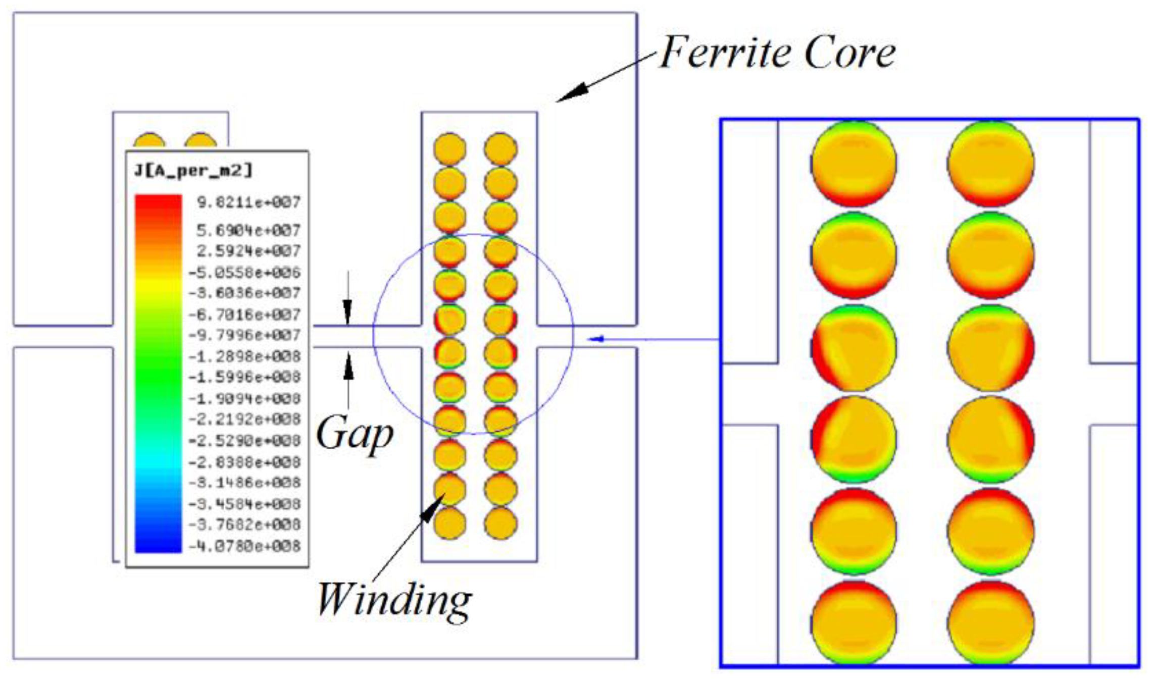
Figure 3.
Main structure of proposed transformer.
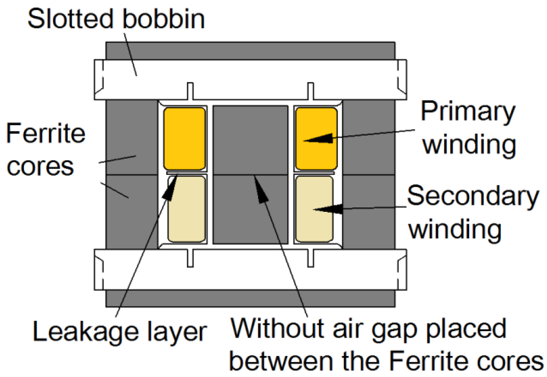
Figure 4.
Fringing effect comparison: (a) Conventional scheme; (b) Proposed scheme.

Figure 5.
Switch controlled inductor parallel to secondary winding of transformer.

Figure 6.
Topology and waveforms of SCI.
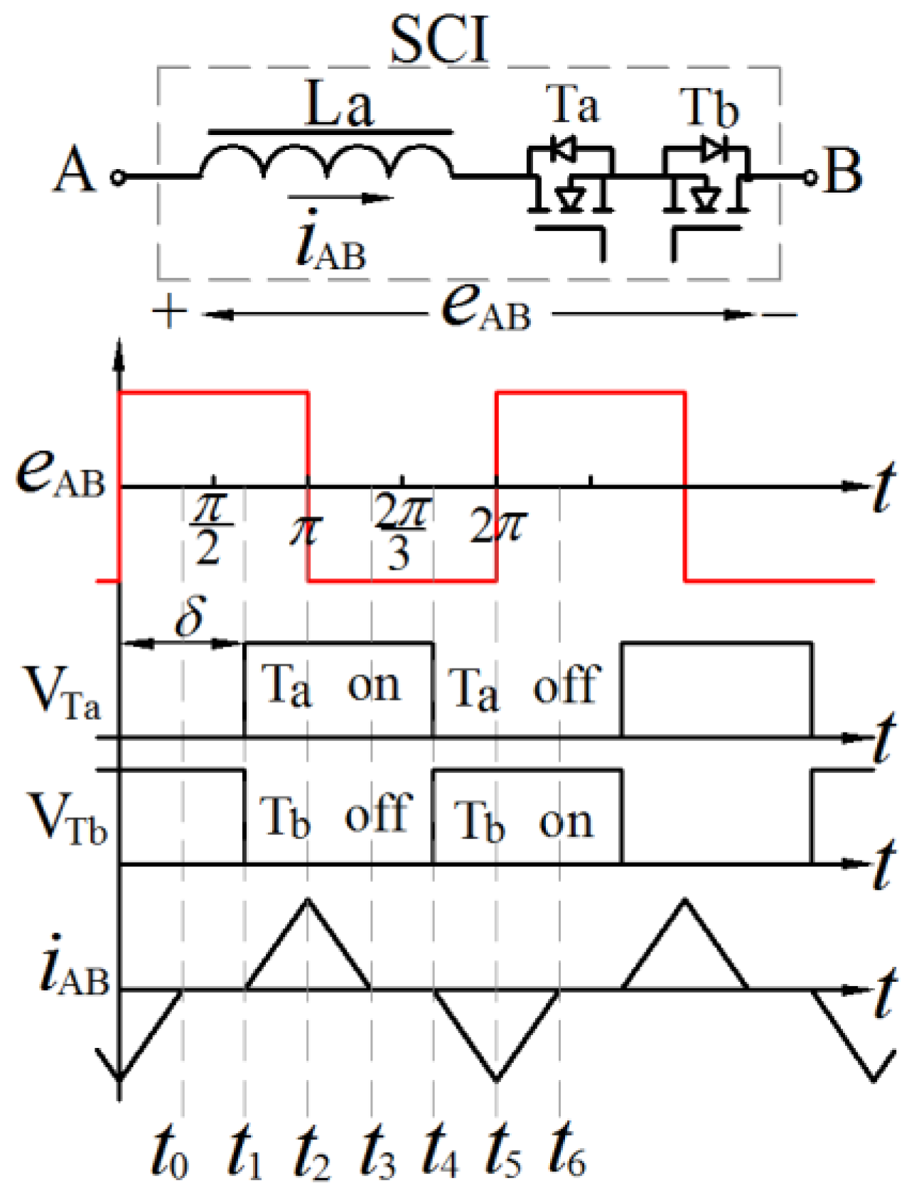
Figure 7.
Equivalent inductance of SCI.
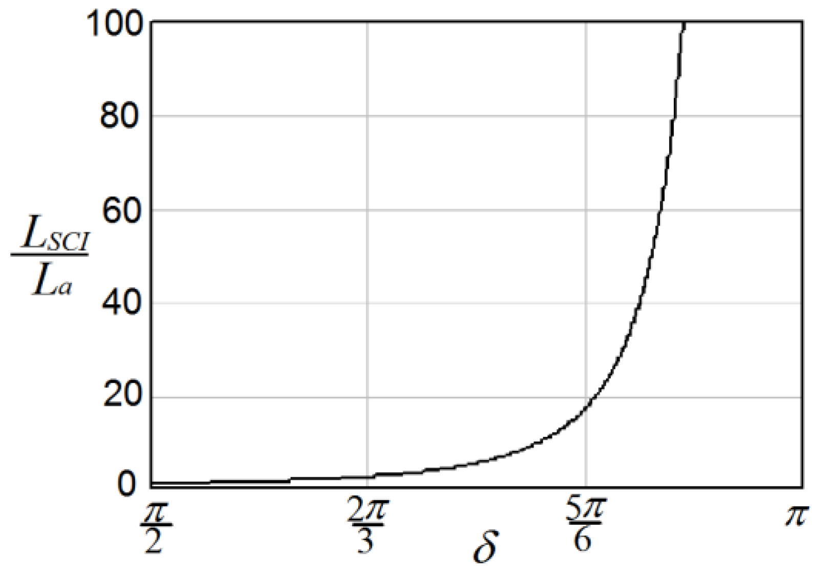
Figure 8.
Equivalent circuit of the proposed LLC resonant tank.
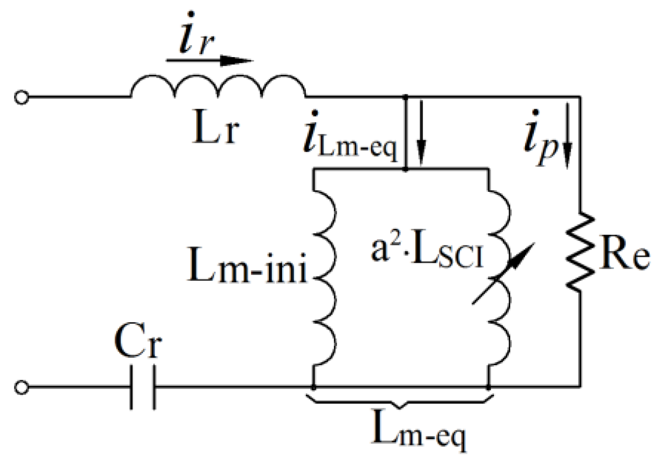
Figure 9.
Magnetic flux in the core of transformer.

Figure 10.
Proposed resonant transformer applied to LLC resonant converter charger.

Figure 11.
Gain curves with different k value.

Figure 12.
Simplified battery charging profile.
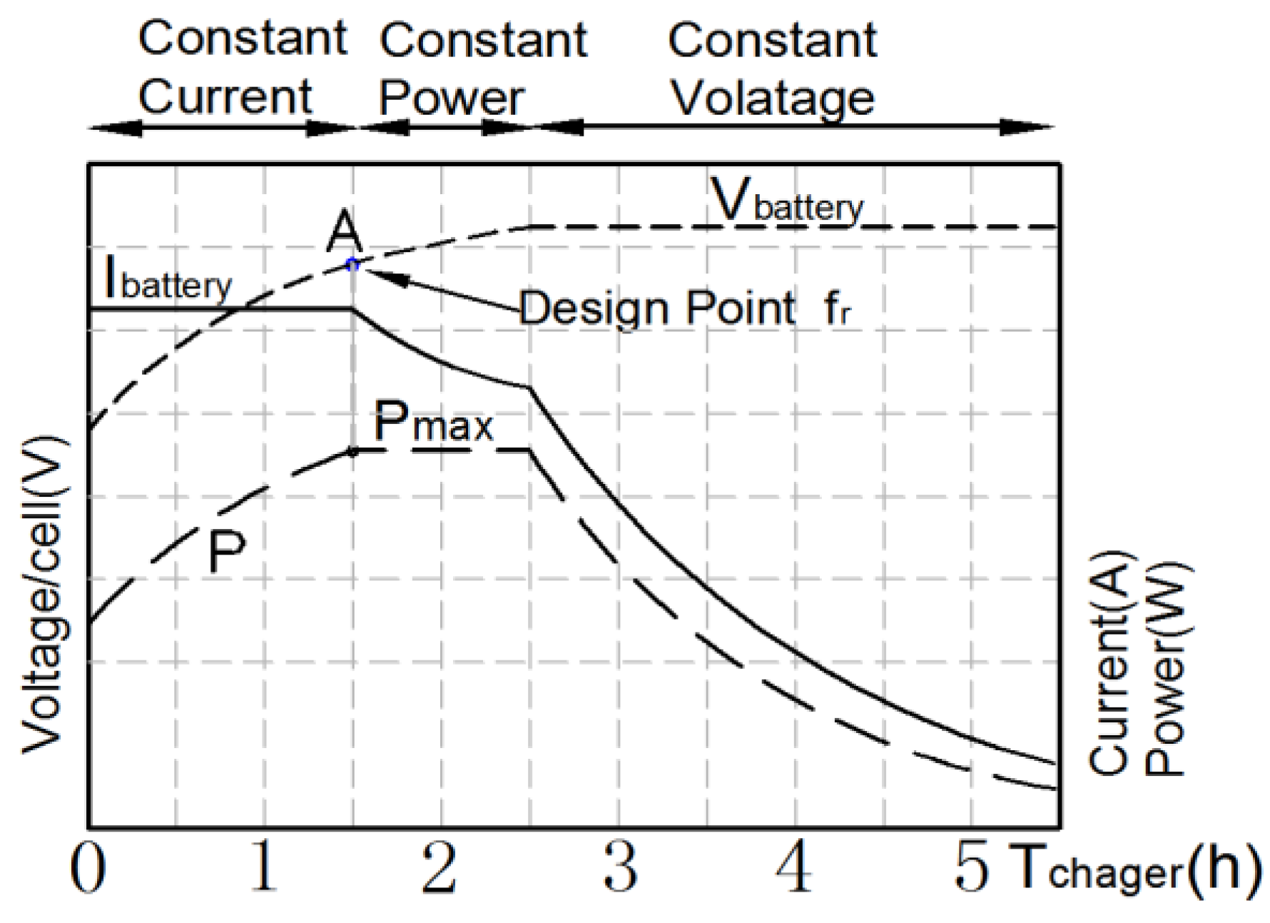
Figure 13.
Change of gain curve during charging process.
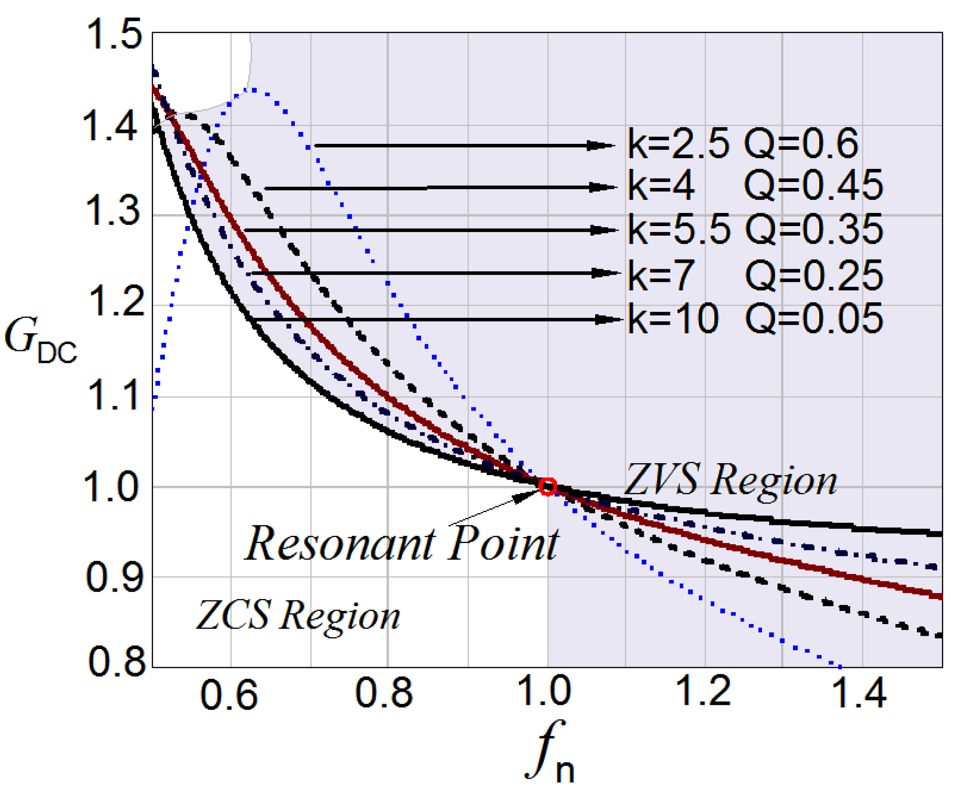
Figure 14.
Experimental waveforms. (a) Constant Current Stage with Vo = 76 V and Io = 8 A (α = 0.5π); (b) Constant Power Stage with Vo = 90 V and Io = 8 A (α = 0.67π); (c) Constant Voltage Stage with Vo = 96 V and Io = 2.5 A (α = 0.79π).
Figure 14.
Experimental waveforms. (a) Constant Current Stage with Vo = 76 V and Io = 8 A (α = 0.5π); (b) Constant Power Stage with Vo = 90 V and Io = 8 A (α = 0.67π); (c) Constant Voltage Stage with Vo = 96 V and Io = 2.5 A (α = 0.79π).

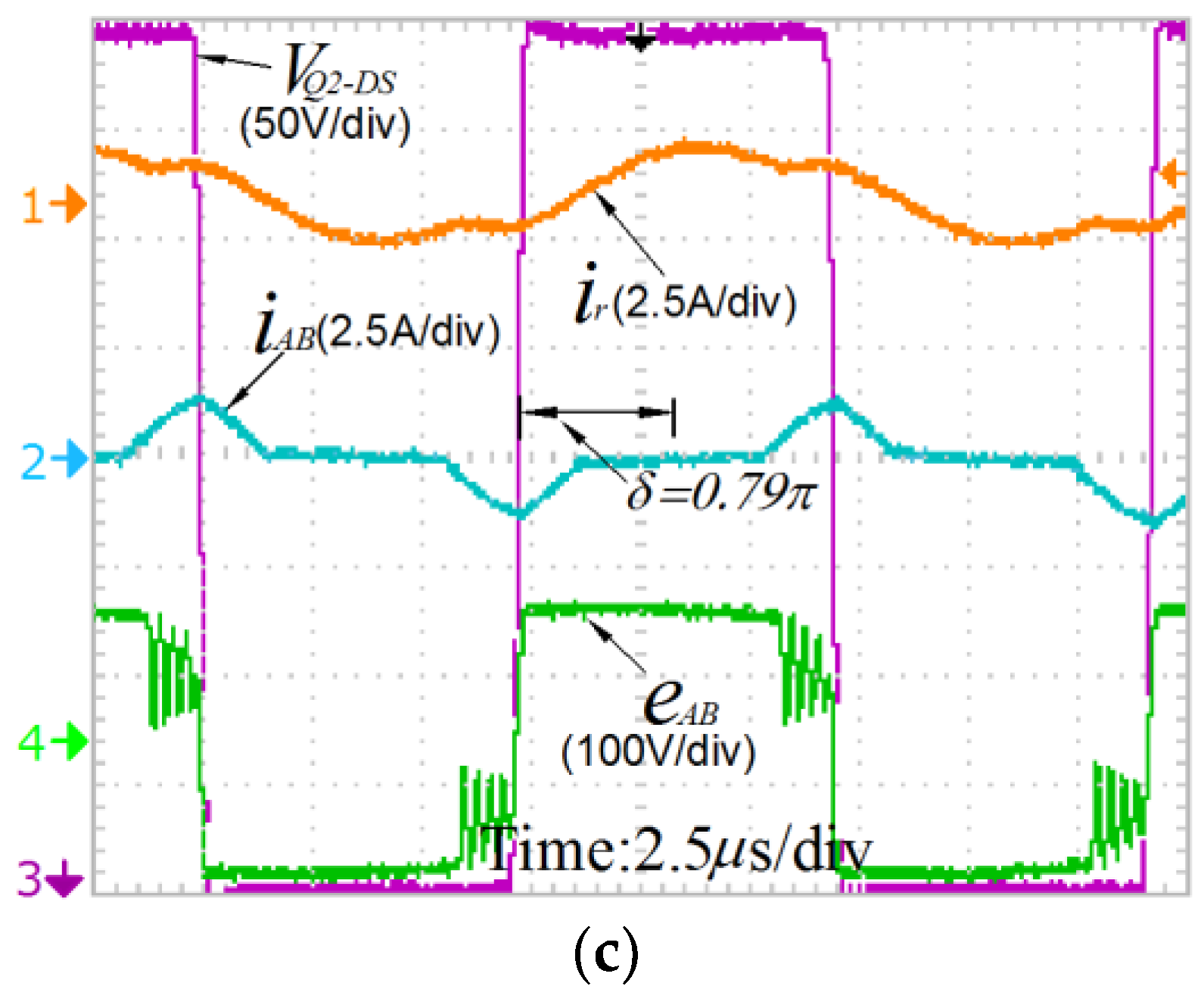
Figure 15.
Temperature rise comparison. (a) The conventional scheme; (b) The proposed scheme.

Figure 16.
Measured loss comparison.
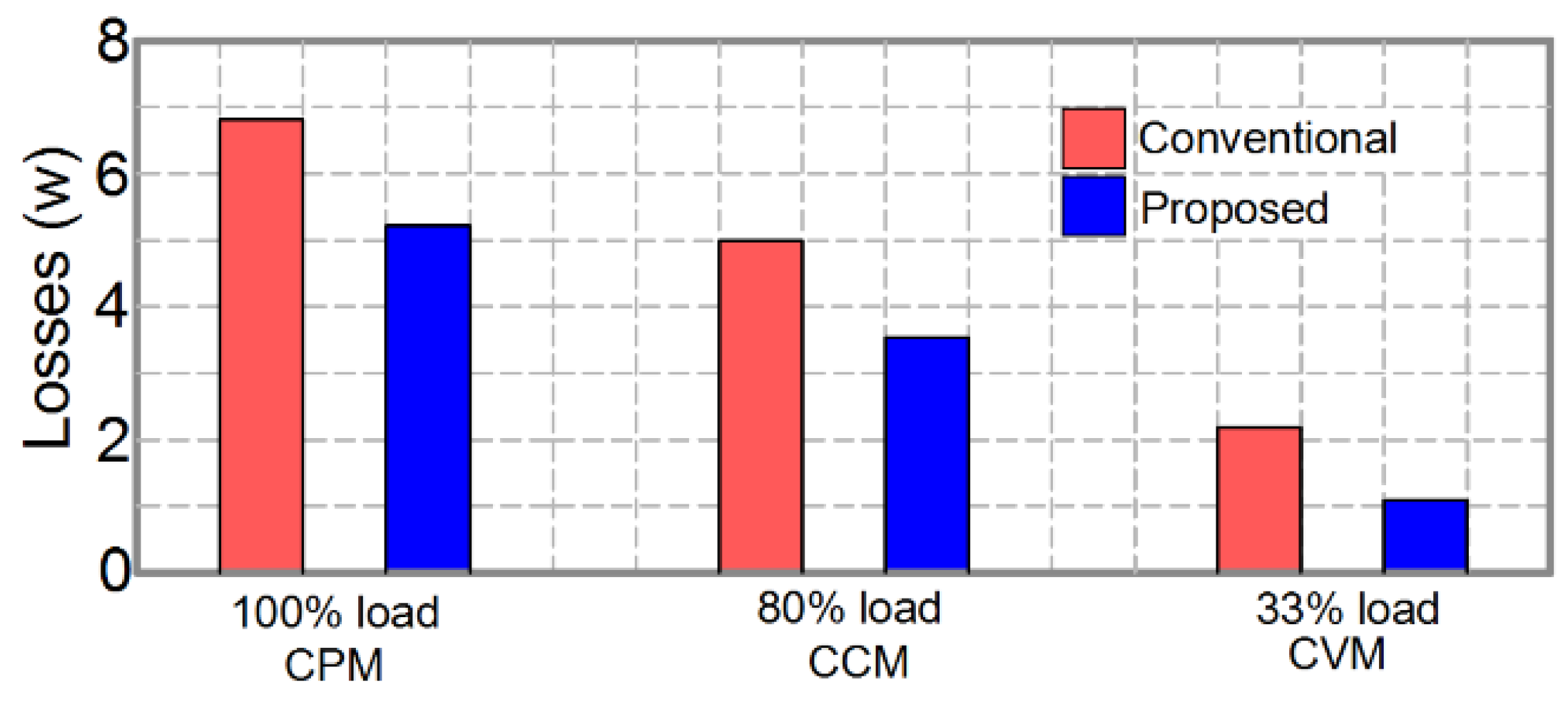
Figure 17.
Efficiency comparison in the whole charging process.

Table 1.
Design Specification.
| Symbol | Description | Value |
|---|---|---|
| Output power | 760 W | |
| Switching frequency | 50 k–300 kHz | |
| Resonant frequency | 85 kHz | |
| Magnetizing inductance | 44 µH | |
| Resonant inductance | 50 µH | |
| a | Turns ratio | 2:1 |
| Temperature rise | 70 °C | |
| Ambient temperature | 40 °C | |
| Resonant rms current | 4.53 A | |
| Magnetizing peak current | 1.26 A | |
| Secondary rms current | 9.1 A | |
| SCI current | 2 A | |
| The total rated VA values of windings | 1466.3 VA |
Table 2.
Material Specifications (Epcos N87).
| Symbol | Description | Value |
|---|---|---|
| Steinmetz parameter | 16.9 | |
| α | Steinmetz parameter | 1.25 |
| β | Steinmetz parameter | 2.35 |
| Saturation magnetic flux | 0.4 T | |
| Window utilization factor | 0.55 | |
| Effective magnetic circuit sectional area | 213 mm2 | |
| γ | Ratio of core loss to winding loss | 1 |
Table 3.
Core and Winding Parameters.
| Symbol | Description | Value |
|---|---|---|
| Cross-section area | 1.73 cm2 | |
| Magnetic path length | 10.3 cm | |
| Window area | 2.78 cm2 | |
| Area product parameter | 4.81 cm4 | |
| Volume of core | 17.70 cm3 | |
| Mean length of a turn | 7.77 cm | |
| Core stacking factor | 1.0 | |
| Copper resistivity (20 °C) | 1.72 µΩ·cm | |
| Constant | 0.00393 |
Table 4.
Core and Winding Parameters.
| AWG | Sectional Area | Resistivity | Diameter |
|---|---|---|---|
| 24 | 0.2047 mm2 | 842.1 µΩ/cm | 0.51 mm |
Table 5.
Loss Calculations.
| Symbol | Description | Value |
|---|---|---|
| Allowed Maximum power loss | 4.9 W | |
| DC winding loss | 1.56 W | |
| AC winding loss | 1.74 W | |
| Core loss | 1.94 W | |
| The loss of SCI | 1.1 W | |
| Total loss | 4.78 W | |
| Transformer efficiency | 99.37% |
© 2018 by the authors. Licensee MDPI, Basel, Switzerland. This article is an open access article distributed under the terms and conditions of the Creative Commons Attribution (CC BY) license (http://creativecommons.org/licenses/by/4.0/).
Share and Cite
MDPI and ACS Style
Zhao, Z.; Xu, Q.; Dai, Y.; Yin, H. Analysis, Design, and Implementation of Improved LLC Resonant Transformer for Efficiency Enhancement. Energies 2018, 11, 3288. https://doi.org/10.3390/en11123288
AMA Style
Zhao Z, Xu Q, Dai Y, Yin H. Analysis, Design, and Implementation of Improved LLC Resonant Transformer for Efficiency Enhancement. Energies. 2018; 11(12):3288. https://doi.org/10.3390/en11123288
Chicago/Turabian StyleZhao, Zhenxing, Qianming Xu, Yuxing Dai, and Hanhang Yin. 2018. "Analysis, Design, and Implementation of Improved LLC Resonant Transformer for Efficiency Enhancement" Energies 11, no. 12: 3288. https://doi.org/10.3390/en11123288
Note that from the first issue of 2016, this journal uses article numbers instead of page numbers. See further details here.