Comparative Study of the Cross-Flow Heat and Mass Exchangers for Indirect Evaporative Cooling Using Numerical Methods

1
College of Mechanical and Energy Engineering, Jimei University, Xiamen 361021, China
2
School of Environment and Chemical Engineering, Xi’an Polytechnic University, Xi’an 710048, China
*
Authors to whom correspondence should be addressed.
Energies 2018, 11(12), 3374; https://doi.org/10.3390/en11123374
Submission received: 4 November 2018
/
Revised: 24 November 2018
/
Accepted: 29 November 2018
/
Published: 2 December 2018
(This article belongs to the Special Issue 2018 EU–China Symposiums on Renewable Energy/Sustainable Energy and Energy Storage Technologies)
Abstract
:This paper presents a comparative study of the cross-flow regenerative heat and mass exchanger (HMX) and the conventional cross-flow HMX for indirect evaporative cooling (IEC) with numerical methods. The objective of this study is mainly to clarify the applicability of the two HMXs. The numerical model was built and validated by existing experimental data. The difference in heat and mass transfer between the two HMXs was revealed by analyzing the change of the temperature and moisture content of the air, and the influence of the main operating parameters on the cooling performance of the HMXs was analyzed. In the typical operating conditions, when the HMXs are used alone, the cooling performance of the regenerative HMX is better than that of the conventional HMX under low supply air flow rate. When the HMXs are used in the multistage evaporative cooling systems with high supply air flow rate, the conventional HMX is more suitable as the first stage of the system to pre-cool the supply air, while the regenerative HMX is more suitable as the second stage to re-cool the supply air.
1. Introduction
It is estimated that the energy consumed by heating, ventilating, and air conditioning (HVAC) accounts for about 50% of the total energy consumption of buildings [1], and that consumed by refrigeration accounts for about 10% to 90% of the total energy consumption of HVAC [2,3]. At present, the refrigeration equipment mostly adopts the conventional mechanical compression cycle, of which the COP is low and then both the primary energy consumption and carbon emissions are large, causing a negative impact on the global climate [4].
By evaporating water to cool the air, evaporative cooling air conditioning is a low energy consumption and environment-friendly HVAC technology [5]. Evaporative cooling includes indirect evaporative cooling (IEC) and direct evaporative cooling (DEC). Compared with DEC, IEC can cool the air without changing its moisture content [6], thus attracting more attention. Theoretically, the conventional HMX for IEC can cool the air to its wet bulb temperature, but in fact, the wet bulb efficiency is only 50% to 60% [7].
The M-cycle proposed by Maisotsenko successfully solves the problem of limited cooling capacity of the conventional HMXs [8,9]. The thermodynamic process of M-cycle can make full use of the air energy, and cool the air to a temperature that is below its wet bulb temperature and approaching its dew point temperature [10], so the HMX in M-cycle is also called regenerative HMX.
Three methods are used to study the HMXs for IEC: experimental method, numerical simulation, and analytical modeling. In terms of the experiments, Bruno F [11] built a counter-flow regenerative HMX, tested it in a commercial and residential application, and found the average dew point effectiveness of the HMX is 65% and 75% respectively.Riangvilaikul et al. [12] carried out experiments on a novel counter-flow dew point evaporative cooler during a typical summer day, and the results showed that the wet bulb effectiveness was almost constant at about 102%, and the dew point effectiveness was 76%. Duan et al. [13] carried out experiments on a counter-flow regenerative HMX, with the results indicating that the wet bulb effectiveness and EER were in the range of 0.55 to 1.06 and 2.8 to 15.5. Xu et al. [14] carried out experiments on a novel counter-flow regenerative HMX. Under the conditions of dry and wet bulb temperatures of 37.8 °C and 21.1 °C and the working air ratio of 0.364, the wet bulb effectiveness and the COP of the HMX achieved 114% and 52.5 respectively. Antonellis et al. [15] carried out 112 experiments on a conventional cross-flow HMX in different conditions, and the results showed that the performance of the HMX was mainly affected by the water flow rate. Hui-Jeong Kim et al. [16] carried out experiments on the cross-flow regenerative HMX and conventional cross-flow HMX in general and regenerative modes, and the results revealed that both the HMXs had higher wet bulb effectiveness in the conventional mode than in the regenerative mode.
In terms of the numerical simulations, Zhao et al. [17] conducted a numerical investigation on a counter-flow regenerative HMX, and the results indicated that the cooling performances were mainly influenced by the channel length and width, working air ratio and air flow rate, and less influenced by the water temperature. Zhan et al. [18] conducted a comparative investigation on two regenerative HMXs, and the results indicated that the cooling capacity and effectiveness of the counter-flow HMX were better than that of the cross-flow HMX, while the cross-flow HMX had a higher COP, under the same conditions. Bolotin et al. [19] conducted a comparative investigation on two cross-flow indirect evaporative coolers, and got the optimum operating conditions for the two coolers on the base of the ε-NTU method. Riangvilaikul et al. [20] presented a numerical investigation on a counter-flow regenerative HMX, and the results showed the wet bulb effectiveness were greater than 100% in any ambient air conditions. Lin et al. [21] found the saturation point of working air in the counter-flow regenerative HMX was mainly affected by the air flow rate and channel space. Xu et al. [22] conducted a CFD simulation on a novel irregular regenerative HMX and compared the numerical results to those of the existing flat-plate exchangers, concluding that the novel irregular exchanger could achieve higher cooling performance and lower pressure drop.
In terms of the analytical models, Hasan [23] and Liu et al. [24] developed modified analytical models for the IEC, respectively, based on the ε-NTU method. The models were validated with the experimental measurements of regenerative HMX available in the literature [12,25]. Hasan stated that the supply air temperature was under-predicted by 7.4% in his model, and Liu et al. stated that the maximum absolute error of the supply air temperature was 2 °C between the predictions and the experimental results. Cui et al. [26] proposed an analytical model via modified LMTD for indirect evaporative coolers, validated the model by the experimental data [27] of a counter-flow regenerative HMX and obtained a maximum discrepancy of 4.3%.
In summary, although most of the recent investigations focus on the counter-flow regenerative HMXs for IEC, the cross-flow regenerative HMX and the conventional cross-flow HMX have got more and more applications. Each of the two cross-flow HMXs can be used alone, or used as one stage in a multistage evaporative cooling system. The purpose of this paper is to reveal the difference in heat and mass transfer between the two HMXs, compare and analyze the effect of the main operating parameters on the HMX performance, and then clarify the applicability of the two HMXs.
2. Description of the Regenerative and Conventional Cross-Flow HMXs
The schematic diagram of the cross-flow regenerative HMX is shown in Figure 1a. The HMX consists of many heat transfer sheets that are supported by the corrugated sheets. One side of each heat transfer sheet is a dry channel and the other side is a wet channel. The air in the dry and wet channels flows in a cross direction. The dry channel of the HMX is divided into upper and lower parts by the guides.
The air flow in the channels is shown in Figure 1b. The supply air flows horizontally and is cooled in the upper part of the dry channel. The working air first flows horizontally in the lower part of the dry channel and then gradually enters the wet channels through the holes located at the sheets, after which the flow direction of the working air becomes vertical upward. The working air is discharged into the atmosphere after heat and mass exchange with the dry channel air and water. Since the working air is pre-cooled in the dry channel, which increases the temperature difference and then enhances the sensible heat transfer between the supply air and the working air, the cross-flow regenerative HMX has better cooling performance than the conventional cross-flow HMX.
The schematic diagram of the conventional cross-flow HMX is shown in Figure 2a, and the air flow in the channels is shown in Figure 2b, where the air in the dry and wet channels also flows in a cross direction. The heat and mass exchange in the two HMXs is similar. The working air of the conventional HMX is not pre-cooled, so its cooling efficiency is lower than that of the regenerative heat exchange.
3. Simulation Method
The adjacent dry and wet channels were selected from Figure 1 and Figure 2, and the channels are divided into several calculation elements by grid method. Each calculation element is composed of a triangular dry air channel, a plate and a triangular wet air channel, as shown in Figure 3. The heat and mass transfer in the calculation elements of both the HMXs are shown in Figure 4. By solving the mass and energy balance equations of each calculation element under the preset boundary conditions, the temperature and moisture content inside the calculation element can be obtained.
To simplify the calculation process, the following assumptions are made:
- (1)
- The heat and mass transfer in the HMXs is in steady state, and no heat exchange occurs between the HMXs and ambience.
- (2)
- The direction of heat transfer between dry channels and wet channels is perpendicular to the plate wall.
- (3)
- The water film in the wet channel is uniformly distributed on the surface of the plate wall, and the water temperature is constant. difference in temperature;
- (4)
- The temperature difference on both sides of the plate wall is ignored.
- (5)
- The temperatures of air and water in the HMXs only change along the flow direction.
The energy balance equation of the element is
The energy balance equation in the dry channel is
The mass balance equation in the wet channel is
The energy balance equation in the wet channel is
Because of the low air velocity in the HMXs channel and the small channel size, the air flow state in the channel is laminar. For the laminar flow, the thermal entry length in the channels can be given as [28]:
For the entrance region of the triangular channel, the Nusselt number could be expressed as [28]:
For the fully developed region of the triangular channel, the Nusselt number is [28]:
The coefficient of mass transfer in the wet channel could be calculated by [28]:
By solving the above discrete equations with the finite element method provided by the Engineering Equation Solver software (Professional version, Klein, S. A., Madison, WI, USA) the air temperature and moisture content parameters in each calculation element, then the supply air temperature, the cooling capacity and effectiveness of the HMXs, can be obtained. Taking the grids number as 400, the Newton iterative method was used to solve the 11054 equations in the model.
4. Computer Model Validation
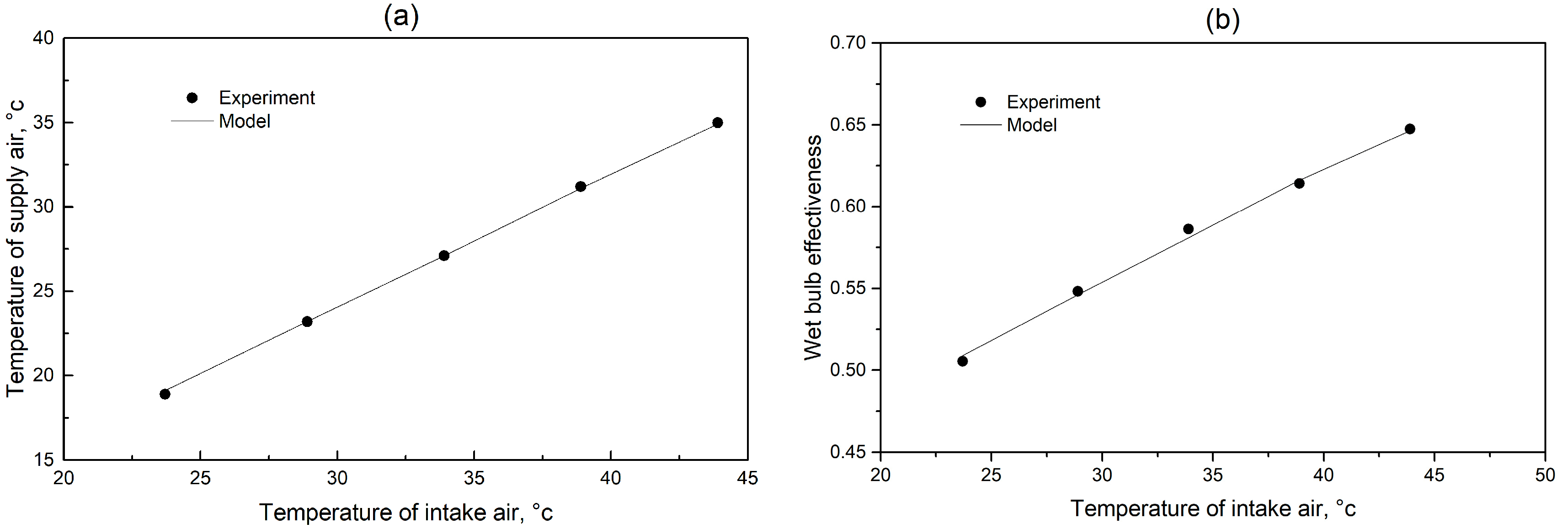
The computer model of the cross-flow regenerative HMX presented in this paper is validated through the published experimental results [29], under the same operational and geometrical conditions as those used in the experimental Cases 1 & 2. The intake air in Cases 1 & 2 had dry bulb temperature of 25 °C to 40 °C, flow rate of 130 m3/h, and relative humidity of 35% and 50% respectively. The validations of the air supply temperature and the wet bulb efficiency are shown in Figure 5 and Figure 6, respectively. For Case 1, the experimental results of the supply air temperature are 0.69 °C to 1.28 °C lower than the numerical results, while for Case 2, the differences are only 0.02 °C to 0.05 °C. The maximum relative error of the supply air temperature is 3.4%. As to the wet bulb effectiveness, the relative error between the experimental and numerical results is 7.3% to 9.4% for Case 1 and 0.2% to 0.4% for Case 2.
It can be seen that the model showed a satisfactory accuracy, thus it can be used to predict the performance of the cross-flow regenerative HMX. The heat and mass transfer occurring in the conventional cross-flow HMX is similar to that in the cross-flow regenerative HMX, so the validation performed above also validated the computer model for the conventional cross-flow HMX.
5. Results and Discussion
The preset conditions for simulation for both the HMXs are shown in Table 1. The simulation results are presented in Section 5.1, Section 5.2 and Section 5.3.
5.1. General Comparison
The simulation results of the two HMXs under the typical operating conditions are shown in Table 2. It can be seen that the cooling performance of the regenerated HMX is significantly better than that of the conventional HMX.
The wet bulb effectiveness of the regenerative HMX is 21.6% higher than that of the conventional HMX. The temperature of supply air is 2.6 °C lower than that of the conventional HMX, making the cooling capacity increase by 20.1% compared with the conventional HMX.
5.2. Heat and Mass Transfer Analysis
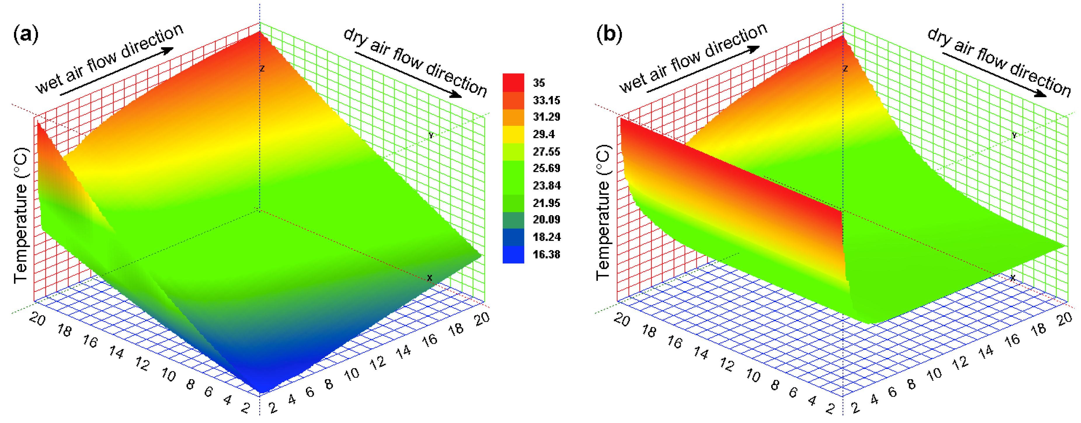
The air temperature distributions in the dry channels of the two HMXs are shown in Figure 7. As shown in Figure 7a, the dry bulb temperature of the outlet air is lower than the wet bulb temperature of the intake air in the dry channel, and shows a non-uniform distribution, particularly in the lower part of the dry channel, where the dry bulb temperature of the outlet air is close to the dew point temperature of the intake air, and the non-uniform distribution is more obvious. The reason is that the working air of the regenerative HMX is pre-cooled in the dry channel and when it just enters the wet channel, its evaporative cooling capacity is the strongest and takes the maximum amount of heat from the supply air. As shown in Figure 7b, the supply air temperature of the conventional HMX is close to the wet bulb temperature of the intake air in the dry channel, indicating the heat transfer between the supply air and the working air is adequate.
The air temperature distributions in the wet channels of the two HMXs are shown in Figure 8. It can be seen that the working air temperature of the conventional HMX is obviously higher than that of the regenerative HMX at the outlet of the dry channel. But at the outlet of the wet channel, the average temperature of the working air of the conventional HMX is significantly lower than that of the regenerative HMX, indicating that the heat transfer between the working air and the supply air is more powerful and sufficient in the regenerative HMX, which is the main reason for the lower temperature of the supply air of the regenerative HMX.
The temperature distributions of the plate walls in the two HMXs are shown in Figure 9. In some regions of the plate wall, the regenerative HMX has a higher wall temperature, and in some regions the situation is just the opposite. But in the whole, the average temperature of the plate wall in the regenerative HMX is higher than that of the conventional HMX, indicating that the heat and mass transfer is stronger in the regenerative HMX.
The air moisture content distributions in the wet channels of the two HMXs are shown in Figure 10. Compared with the conventional HMX, the air moisture content in the wet channel of the regenerative HMX is higher, which indicates that the evaporation rate of water is higher and the effect of evaporative cooling between the water and the working air is stronger in the regenerative HMX, and as a result, more heat is taken away from the supply air and a lower supply air temperature is obtained in the regenerative HMX.
5.3. Impact of Intake Air Parameters
5.3.1. Impact of Intake Air Temperature
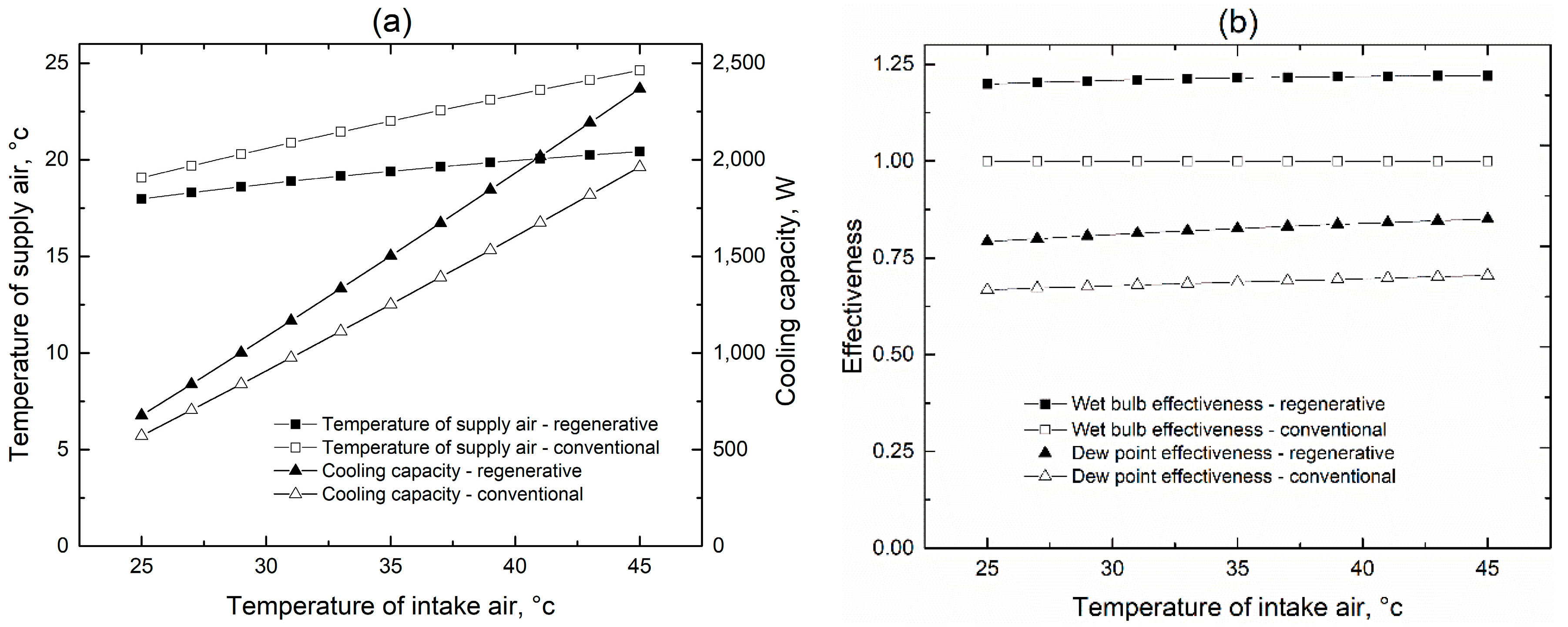
The intake air temperature changes in the range of 25 °C to 45 °C, while the other parameters remain at the values shown in Table 1. The impact of the intake air temperature on the cooling performance of the two HMXs is shown in Figure 11.
It can be seen from Figure 11 that the cooling performance of the regenerative HMX is always better than that of the conventional HMX, and the advantage becomes more obvious with the increase of the intake air temperature. When the intake air temperature is 45 °C, the supply air temperature of the regenerative HMX is 4.2 °C lower and then the cooling capacity is 413 W higher than that of the conventional HMX. The effectiveness of both the HMXs remains almost constant, mainly because of the low air flow rate (Table 1) used in the calculation. The wet bulb effectiveness of the regenerative HMXs is always about 20% higher and the dew point effectiveness is always about 15% higher than that of the conventional HMX.
5.3.2. Impact of Intake Air Moisture Content
The moisture content of intake air changes in the range of 4 g/kg to 26 g/kg, while the other parameters are kept constant at the values shown in Table 1. The impact of intake air moisture content on the cooling performance of both the HMXs is shown in Figure 12.
As shown in the Figure 12a, the moisture content in intake air has great influence on the cooling capacity and the supply air temperature of both the HMXs, especially the regenerative HMX. When the moisture content of the intake air is 4 g/kg, the supply air temperature of the regenerative HMX is 3.5 °C lower and the cooling capacity is 335 W higher than that of the conventional HMX, and when the moisture content of the intake air is 26 g/kg, the differences are reduced to 0.9 °C and 82 W, respectively.
The moisture content of the inlet air has little influence on the wet bulb effectiveness but obvious influence on the dew point effectiveness of both the HMXs (Figure 12b). When the moisture content of intake air is lower, the difference between the dry bulb and the dew point temperature of the air is larger, making the dew point effectiveness of both the HMXs relatively low. With the increase of the moisture content of intake air, the difference between the dry bulb and the dew point temperatures decreases gradually, improving the dew point effectiveness of both the HMXs. The increase of the moisture content in the intake air weakens the evaporative cooling effect between the water and the working air in both the HMXs, so the cooling capacity is gradually reduced. To sum up, the cooling effectiveness cannot be used independently to measure the HMX performance. In general, using both the HMXs in the dry and hot climate will achieve better results.
5.3.3. Impact of Supply Air Flow Rate
The impact of the supply air flow rate on the cooling performance of both the HMXs is investigated through two cases. In Case 1, the intake air of the dry channel is not pre-cooled, while in Case 2, it is pre-cooled.
Both the HMXs can be used alone, or used as the first or second stage of a multistage evaporative cooling system (e.g., two-stage indirect evaporative coolers + one-stage direct evaporative cooler). Case 1 corresponds to the situation that the two HMXs are used alone or used as the first stage of a multistage evaporative cooling system, and Case 2 corresponds to the situation that the two HMXs are used as the second stage of a multistage evaporative cooling system.
Case 1 (Without pre-cooling of dry channel air)
Both the flow rates of supply air and working air vary in the range of 300 m3/h to 3000 m3/h, and the other parameters are unchanged as shown in Table 1. The impact of supply air flow rate on the cooling performance of both the HMXs is presented in Figure 13 when the dry channel air is not pre-cooled.
As can be seen from Figure 13a that the supply air temperature of both the HMXs rises with the supply air flow rate. When the supply air flow rate is low, the supply air temperature of the regenerative HMX is less than that of the conventional HMX, but the phenomenon is reversed when the supply air flow rate is greater than 957 m3/h. The reason for the reversal is analyzed below. When the heat transfer area of the plate in both the HMXs is equal, the heat transfer area between the supply air and the working air in the conventional HMX is greater than that in the regenerative HMX (as shown in Figure 1b and Figure 2b). The advantage of heat transfer area of the conventional HMX becomes increasingly apparent when the supply air flow rate increases. The variation of cooling capacity in both the HMXs is similar to that of the supply air temperature. When the supply air flow rate is 3000 m3/h, the cooling capacity of the regenerative HMX is 9.7% lower than that of the conventional HMX. The effectiveness of both the HMXs decreases with the increase of the supply air flow rate (Figure 13b).
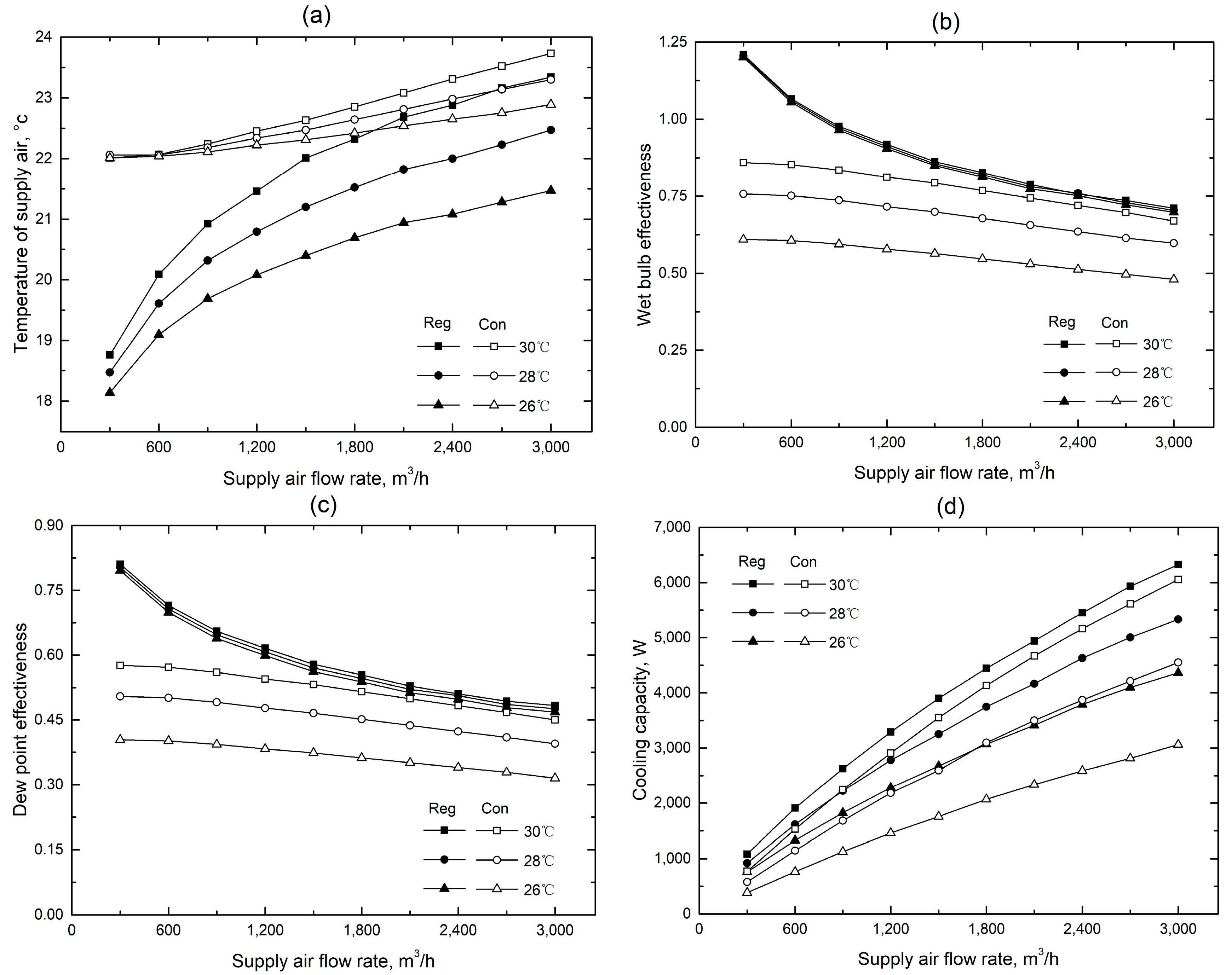
Case 2 (With pre-cooling of dry channel air)
Compared with the preset parameters for Case 1, only the intake temperature of the dry channel air is reset for Case 2. It is set at 35 °C for Case 1, while set at 30 °C, 28 °C and 26 °C for Case 2. The dry channel air of the regenerative HMX includes the supply air and the working air, so both of them are pre-cooled. In the conventional HMX, the working air comes from the ambient air, and the supply air, which is the only dry channel air, is pre-cooled.
It can be seen from Figure 14a that the supply air temperature of both the HMXs rises and the temperature difference between them gradually decreases as the supply air flow rate increases. The supply air temperature of the regenerative HMX is always lower than that of the conventional HMX. As the pre-cooling of the dry channel air deepens, the supply air temperature of both the HMXs gradually decreases. The temperature drop of supply air in the regenerative HMX is greater. As shown in the Figure 14d, the cooling capacity of the regenerative HMX is always greater than that of the conventional HMX. More sufficient precooling of the dry channel air and larger flow rate of the supply air lead to more obvious superiority of the regenerative HMX. When the intake air temperature of the dry channel is 26 °C, and the supply air flow rate is 3000 m3/h, the cooling capacity of the regenerative HMX is 42.4% higher than that of the conventional HMX.
The extent that the dry channel air is pre-cooled has a greater impact on the effectiveness of the regenerative HMX, but less impact on the effectiveness of the conventional HMX.
To sum up, when the supply air flow rate is low, the regenerative HMX is more suitable to use alone. When the supply air flow rate is high, the conventional HMX is more suitable as the first stage of a multistage evaporative cooling system to pre-cool the supply air, while the regenerative HMX is more suitable as the second stage of a multistage evaporative cooling system to re-cool the supply air.
6. Conclusions
This study presents a performance comparison between the cross-flow regenerative HMX and the conventional cross-flow HMX for IEC. Using the numerical method, the influence of the main operating parameters on the cooling performance of both the HMXs was analyzed, and the results show that:
- (1)
- Under the typical operating parameters shown in Table 1, the cooling capacity of the regenerative HMX is 20.1% higher than that of the conventional HMX. When the supply air flow rate increases from 300 m3/h to 3000 m3/h and the other parameters remain unchanged, the cooling capacity of the conventional HMX is 9.7% higher than that of the regenerative HMX.
- (2)
- More sufficient pre-cooling of the dry channel air and higher flow rate of the supply air lead to better cooling performance of the regenerative HMX. When the intake temperature of the dry channel air is 26 °C, the supply air flow rate is 3000 m3/h, and the other parameters remain at the values shown in Table 1, the cooling capacity of the cross-flow regenerative HMX is 42.4% higher than that of the conventional cross-flow HMX.
- (3)
- When both the HMXs are used alone, the cooling performance of the regenerative HMX is better than that of the conventional HMX in the case of low supply air flow rate. When they are used in the multistage evaporative cooling systems with high supply air flow rate, the conventional HMX is more suitable as the first stage of the system to pre-cool the supply air, while the regenerative HMX is more suitable as the second stage to re-cool the supply air.
Author Contributions
Conceptualization, Y.W. and X.H.; methodology, Y.W., X.H. and L.L.; software, Y.W.; validation, Y.W.; formal analysis, Y.W. and L.L.; writing—original draft preparation, Y.W.; writing—review and editing, Y.W.
Funding
This research was funded by the National Key R&D Program of China (No. 2016YFC0700400); Natural Science Foundation of Fujian Province, China (Nos. 2018J01486, 2018J01487, 2016J01245); Department of Education, Fujian Province (No. JA15294).
Conflicts of Interest
The authors declare no conflict of interest.
Nomenclature
| A | heat transfer area, m2 |
| cp | specific heat, kJ/kg °C |
| d | moisture content, kg/kg |
| h | convection coefficient, W/ (m2 °C) |
| hm | mass transfer coefficient, m/s |
| i | enthalpy, kJ/kg |
| L | length, m |
| m | air mass flow rate, kg/s |
| rw | vaporization heat, kJ/kg |
| T | temperature, °C |
| De | equivalent diameter, m |
| Le | Lewis number |
| Nu | Nusselt number |
| Pr | Prandtl number |
| Re | Reynolds number |
| Greek | |
| ρ | Density, kg/m3 |
| μ | dynamic viscosity, N∙s/m2 |
| Subscripts | |
| l | latent heat |
| w | wall |
| 1 | dry side |
| 2 | wet side |
References
- Chua, K.J.; Chou, S.K.; Yang, W.M.; Yan, J. Achieving better energy-efficient air conditioning—A review of technologies and strategies. Appl. Energy 2013, 104, 87–104. [Google Scholar] [CrossRef]
- Zimmermann, M.; Remund, S. IEA-ECBCS Annexure 28 Subtask 2, Ground Coupled Air Systems. In Low Energy Cooling-Technology Selection and Early Design Guidance; Barnard, N., Jaunzens, D., Eds.; Construction Research Communications: Ellesmere Port, UK, 2001; pp. 95–109. [Google Scholar]
- Behne, M. Alternatives to Compressive Cooling in Non-Residential Buildings to Reduce Primary Energy Consumption; Final Report; Lawrence Berkeley National Laboratory: Berkeley, CA, USA, 1997.
- Sultan, M.; El-Sharkawy, M.; Miyazaki, T.; Saha, B.B.; Koyama, S. An overview of solid desiccant dehumidification and air conditioning systems. Renew. Sustain. Energy Rev. 2015, 46, 16–29. [Google Scholar] [CrossRef]
- Steven, B.J.; Domanski, P.A. Review of alternative cooling technologies. Appl. Therm. Eng. 2014, 64, 252–262. [Google Scholar] [CrossRef]
- Duan, Z.; Zhan, C.; Zhang, X.; Mustafa, M.; Zhao, X.; Alimohammadisagvand, B.; Hasan, A. Indirect evaporative cooling: Past, present and future potentials. Renew. Sustain. Energy Rev. 2012, 16, 6823–6850. [Google Scholar] [CrossRef]
- Huang, X. Evaporative Air Conditioning Theory and Application; China Building Industry Press: Beijing, China, 2010; pp. 100–110. ISBN 9787112121953. (In Chinese) [Google Scholar]
- Maisotsenko, V.S.; Gillan, L.E.; Heaton, T.L.; Gillan, A.D. Method and Plate Apparatus for Dew Point Evaporative Cooler. US Patent No. US6581402, 24 June 2003. [Google Scholar]
- Zhan, C.; Zhao, X.; Smith, S.; Riffat, S.B. Numerical study of a M-cycle cross-flow heat exchanger for indirect evaporative cooling. Build. Environ. 2011, 46, 657–668. [Google Scholar] [CrossRef]
- Mahmood, M.H.; Sultan, M.; Miyazaki, T.; Koyama, S.; Maisotsenko, V.S. Overview of the Maisotsenko cycle—A way towards dew point evaporative cooling. Renew. Sustain. Energy Rev. 2016, 66, 537–555. [Google Scholar] [CrossRef]
- Bruno, F. On-site experimental testing of a novel dew point evaporative cooler. Energy Build. 2011, 43, 3475–3483. [Google Scholar] [CrossRef]
- Riangvilaikul, B.; Kumar, S. An experimental study of a novel dew point evaporative cooling system. Energy Build. 2010, 42, 637–644. [Google Scholar] [CrossRef]
- Duan, Z.; Zhan, C.; Zhao, X.; Dong, X. Experimental study of a counter-flow regenerative evaporative cooler. Build. Environ. 2016, 104, 47–58. [Google Scholar] [CrossRef]
- Xu, P.; Ma, X.; Zhao, X.; Fancey, K. Experimental investigation of a super performance dew point air cooler. Appl. Energy 2017, 203, 761–777. [Google Scholar] [CrossRef]
- Antonellis, S.D.; Joppolo, C.M.; Liberati, P.; Milani, S.; Molinaroli, L. Experimental analysis of a cross flow indirect evaporative cooling system. Energy Build. 2011, 121, 130–138. [Google Scholar] [CrossRef]
- Kim, H.J.; Ham, S.W.; Yoon, D.S.; Jeong, J.W. Cooling performance measurement of two cross-flow indirect evaporative coolers in general and regenerative operation modes. Appl. Energy 2017, 195, 268–277. [Google Scholar] [CrossRef]
- Zhao, X.; Li, J.; Riffat, S.B. Numerical study of a novel counter-flow heat and mass exchanger for dew point evaporative cooling. Appl. Therm. Eng. 2008, 28, 1942–1951. [Google Scholar] [CrossRef]
- Zhan, C.; Duan, Z.; Zhao, X. Comparative study of the performance of the M-cycle counter-flow and cross-flow heat exchangers for indirect evaporative cooling—Paving the path toward sustainable cooling of buildings. Energy 2011, 36, 6790–6805. [Google Scholar] [CrossRef]
- Bolotin, S.; Vager, B.; Vasilijev, V. Comparative analysis of the cross-flow indirect evaporative air coolers. Int. J. Heat Mass Transfer. 2015, 88, 224–235. [Google Scholar] [CrossRef]
- Riangvilaikul, B.; Kumar, S. Numerical study of a novel dew point evaporative cooling system. Energy Build. 2010, 42, 2241–2250. [Google Scholar] [CrossRef]
- Lin, J.; Thu, K.; Bui, T.; Wang, R.; Ng, K.C.; Chua, K.J. Study on dew point evaporative cooling system with counter-flow configuration. Energy Convers. Manag. 2016, 109, 153–165. [Google Scholar] [CrossRef]
- Xu, P.; Ma, X.; Diallo, T.M.O.; Zhao, X.; Fancey, K.; Li, D.; Chen, H. Numerical investigation of the energy performance of a guideless irregular heat and mass exchanger with corrugated heat transfer surface for dew point cooling. Energy 2016, 109, 803–817. [Google Scholar] [CrossRef]
- Hasan, A. Going below the wet-bulb temperature by indirect evaporative cooling: Analysis using a modified e-NTU method. Appl. Energy 2012, 89, 237–245. [Google Scholar] [CrossRef]
- Liu, Z.; Allen, W.; Modera, M. Simplified thermal modeling of indirect evaporative heat exchangers. HVACR Res. 2013, 19, 257–267. [Google Scholar] [CrossRef]
- Hasan, A. Indirect evaporative cooling of air to a sub-wet bulb temperature. Appl. Therm. Eng. 2010, 30, 2460–2468. [Google Scholar] [CrossRef]
- Cui, X.; Chua, K.J.; Islam, M.R.; Yang, W.M. Fundamental formulation of a modified LMTD method to study indirect evaporative heat exchangers. Energy Convers. Manag. 2014, 88, 372–381. [Google Scholar] [CrossRef]
- Hsu, S.T.; Lavan, Z.; Worek, W.M. Optimization of wet-surface heat exchangers. Energy 1989, 14, 757–770. [Google Scholar] [CrossRef]
- Yang, S.; Tao, W. Heat Transfer, 4th ed.; Higher Education Press: Beijing, China, 2006; pp. 229–280. ISBN 9787040189186. (In Chinese) [Google Scholar]
- Qiu, G. A Novel Evaporative/Desiccant Cooling System. Ph.D. Thesis, The University of Nottingham, Nottingham, UK, 2007. [Google Scholar]
Figure 1.
Cross-flow regenerative heat and mass exchanger (HMX). (a) Schematic. (b) Air flow in the channels.
Figure 1.
Cross-flow regenerative heat and mass exchanger (HMX). (a) Schematic. (b) Air flow in the channels.

Figure 2.
Conventional cross-flow HMX. (a) Schematic. (b) Air flow in the channels.
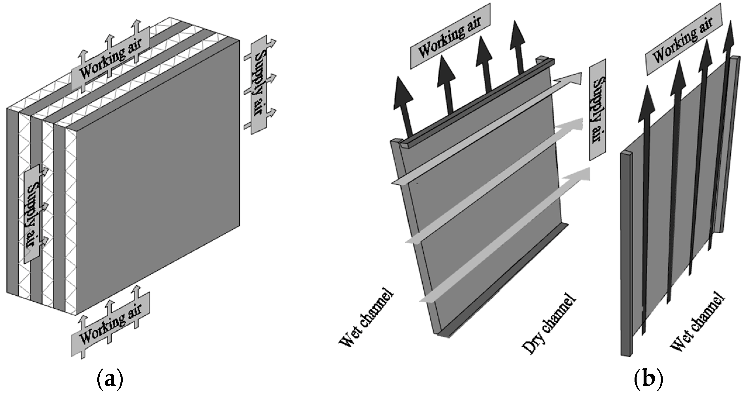
Figure 3.
Triangle channels for simulation.
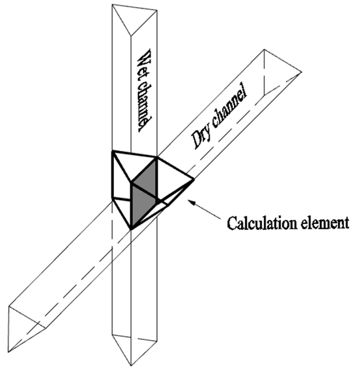
Figure 4.
Calculation element for simulation. (a) Regenerative HMX. (b) Mass and energy balance. (c) Conventional HMX.
Figure 4.
Calculation element for simulation. (a) Regenerative HMX. (b) Mass and energy balance. (c) Conventional HMX.

Figure 5.
Model validation—Case 1. (a) Temperature of supply air. (b) Wet-bulb effectiveness.

Figure 6.
Model validation—Case 2. (a) Temperature of supply air. (b) Wet-bulb effectiveness.

Figure 7.
The air temperature distribution in the dry channel: (a) Regenerative. (b) Conventional.
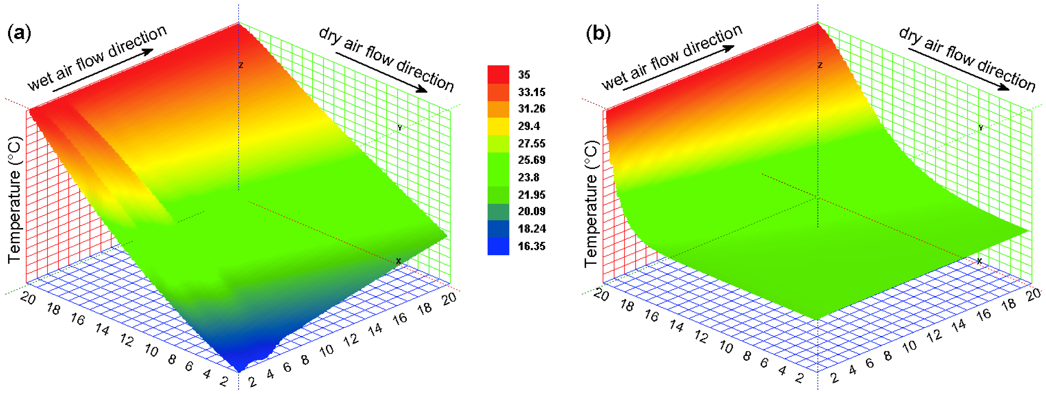
Figure 8.
The air temperature distribution in the wet channel: (a) Regenerative. (b) Conventional.

Figure 9.
The temperature distribution of plate wall: (a) Regenerative. (b) Conventional.

Figure 10.
The air moisture content distribution in the wet channel: (a) Regenerative. (b) Conventional.
Figure 10.
The air moisture content distribution in the wet channel: (a) Regenerative. (b) Conventional.

Figure 11.
Impact of intake air temperature: (a) Supply air temperature and cooling capacity. (b) Effectiveness.
Figure 11.
Impact of intake air temperature: (a) Supply air temperature and cooling capacity. (b) Effectiveness.

Figure 12.
Impact of intake air moisture content: (a) Supply air temperature and cooling capacity. (b) Effectiveness.
Figure 12.
Impact of intake air moisture content: (a) Supply air temperature and cooling capacity. (b) Effectiveness.
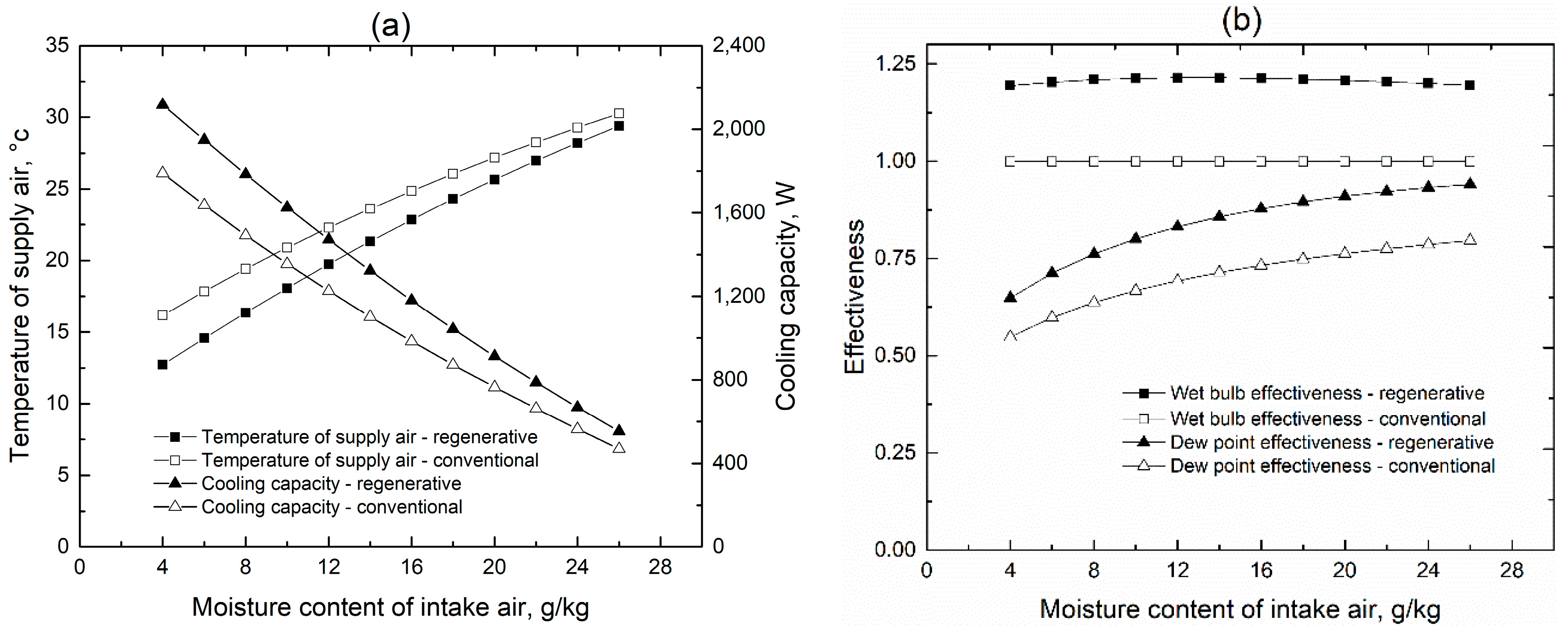
Figure 13.
Impact of supply air flow rate (Case 1): (a) Supply air temperature and cooling capacity. (b) Effectiveness.
Figure 13.
Impact of supply air flow rate (Case 1): (a) Supply air temperature and cooling capacity. (b) Effectiveness.
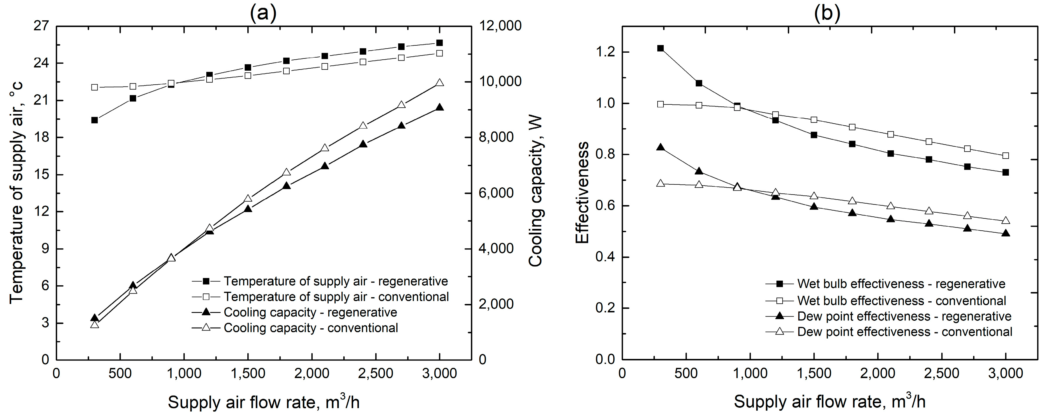
Figure 14.
Impact of supply air flow rate (Case 2): (a) Supply air temperature. (b) Wet bulb effectiveness. (c) Dew point effectiveness. (d) Cooling capacity.
Figure 14.
Impact of supply air flow rate (Case 2): (a) Supply air temperature. (b) Wet bulb effectiveness. (c) Dew point effectiveness. (d) Cooling capacity.


Table 1.
Preset conditions for two HMXs.
| Parameters | Value |
|---|---|
| Intake air temperature (°C) | 35 |
| Moisture content (g/kg) | 11.3 |
| Working to supply air ratio | 1 |
| Supply air flow rate (m3/h) | 300 |
| Channel height (m) | 0.004 |
| HMX length/width (m) | 1.2 |
| Working to supply air area ratio * | 1.25 |
| Channels number | 184 |
* For the regenerative HMX.
Table 2.
Simulation results under preset conditions for two HMXs.
| Parameters | Regenerative HMX | Conventional HMX |
|---|---|---|
| Supply air temperature (°C) | 19.4 | 22 |
| Relative humidity of supply air (%) | 81.5 | 69.1 |
| Wet bulb effectiveness (%) | 121.5 | 99.9 |
| Dew point effectiveness (%) | 82.6 | 68.7 |
| Cooling capacity (W) | 1503 | 1251 |
© 2018 by the authors. Licensee MDPI, Basel, Switzerland. This article is an open access article distributed under the terms and conditions of the Creative Commons Attribution (CC BY) license (http://creativecommons.org/licenses/by/4.0/).
Share and Cite
MDPI and ACS Style
Wang, Y.; Huang, X.; Li, L. Comparative Study of the Cross-Flow Heat and Mass Exchangers for Indirect Evaporative Cooling Using Numerical Methods. Energies 2018, 11, 3374. https://doi.org/10.3390/en11123374
AMA Style
Wang Y, Huang X, Li L. Comparative Study of the Cross-Flow Heat and Mass Exchangers for Indirect Evaporative Cooling Using Numerical Methods. Energies. 2018; 11(12):3374. https://doi.org/10.3390/en11123374
Chicago/Turabian StyleWang, Yugang, Xiang Huang, and Li Li. 2018. "Comparative Study of the Cross-Flow Heat and Mass Exchangers for Indirect Evaporative Cooling Using Numerical Methods" Energies 11, no. 12: 3374. https://doi.org/10.3390/en11123374
Note that from the first issue of 2016, this journal uses article numbers instead of page numbers. See further details here.