1. Introduction
Convective thermal transmission in partially open cavities with solid heat-conducting walls and heat-generating elements is very important in different engineering supplements, e.g., cooling of electronics, heat-transfer devices, chemical apparatus and solar collectors. It should be noted that nowadays one of the major challenges is a creation of effective cooling system for reducing the working temperature for heat-generating elements inside different electronic cabinets. Optimal approach for solution to this problem is an employment of computer power of modern computational systems combined with numerical methods of hydrodynamics and heat transfer. Different interesting and useful theoretical and experimental data have been announced during last decades.
Thus, Dwesh K. Singh and S.N. Singh [
1] examined numerically 2D conjugate free convection-radiation heat transfer in an open air domain under the influence of uniform volumetric heat generating element on the vertical border. They used Hottel’s Crossed-string technique for calculation of view factors during the surface radiation analysis. Taking into account the obtained results, correlations were derived for maximum dimensionless heater temperature for various positions. Mikhailenko et al. [
2] conducted a computational analysis of convective heat transfer and thermal radiation inside a rotating cavity with a heat-generating element. They showed that domain rotating velocity and surface emissivity of surrounding walls and heated source are very effective control parameters for creation of optimal cooling system. Chen et al. [
3] evaluated the convection-conduction thermal transmission in an open partially porous domain. They chose the lattice Boltzmann approach to solve equations. Naylor et al. [
4] studied numerically thermogravitational convection from a window glazing with an insect shield simulated like a porous layer and found that the shield has negligible influence on convective thermal transmission for high values of
Ra. Astanina et al. [
5] analyzed numerically thermogravitational convection in a partially porous cavity with a heat-generating source. The authors demonstrated that porous layer thickness and variable viscosity parameter of the working medium allows optimizing the passive cooling arrangement owing to an enhancement of cooling impact from the cold vertical borders. Rahman et al. [
6] examined the influence of Ohmic heating and magnetic field on mixed convection heat and mass transfer in a horizontal channel using finite element technique.Their results demonstrated that the aforesaid fields affect the flow structure, thermal and mass transmnission. Saha et al. [
7] worked on MHD mixed convection under the influence of internal heat generation/absorption. They revealed that the average Nusselt number is a decreasing function of the heat generation and an increasing function of heat absorption. Gangawane [
8] made a numerical study on MHD thermograviational convection in an open cavity. The author found that the domain of interest with the inclined magnetic field at the angle π/4 illustrates the highest thermal transmission restriction than other analyzed conditions. Dong and Li [
9] studied the conjugate free convection in a composite closed space by vorticity–stream function technique. They found that used material, geometry and
Ra are efffective parameters for an optimization of thermal transmission. Bilgen [
10] performed a work on free convection in closed spaces having thin obstacle on heated border. He observed that length and location of this obstacle are very good control elements for an intensification of liquid circulation and thermal transmission.
Nowadays, for an intensification of heat transfer within different engineering systmes the nanosized metal or metal oxide particles are used [
11,
12,
13]. Different experimental studies showed that an inclusion of nanoparticles of low concentration can improve the heat transfer performance inside the system [
14,
15]. Thus, Asirvatham et al. [
14] performed experiments for steady convection thermal transmission of de-ionized water combined with copper oxide nanoparticles of low concentration (0.003% by volume) in a copper tube. They showed 8% enhancement of the convective heat transfer coefficient of the nanofluid even with a low volume concentration of nanosized copper oxide particles. Raei et al. [
15] experimentally studied the circulation and thermal transmission parameters of three kinds of the nanofluids within a fin-and-tube heat exchanger. It was revealed that an inclusion of alumina nanosized particles into the water enhances the overall heat transfer parameter and friction factor up to 20% and 5%, respectively. Taking into account such heat transfer enhancement, these approach can be used for an intesification of cooling process inside the electronic cabinets. Several theoretical and experimental works were published. Thus, Mehrez et al. [
16] solved numerically a problem on mixed convection combined with entropy production with an open region filled with nanoliquid under the bottom heating impact. They found that the thermal transmission combined with entropy production are enhanced with the growth of
Re,
Ri and nanoparticles concentration, and changed with region
AR and nanoparticle types. Sheremet et al. [
17] analyzed mixed convective heat and mass transport inside a porous nanoliquid domain with open border under the impacts of thermophoresis and Brownian diffusion. They revealed that the average Nusselt parameter is a growing mapping of
Ra and
Re and a reduced mapping of
Le. Sheremet et al. [
18] investigated nanoliquid free convection within a semi-open tall wavy cavity under the effects of horizontal temperature difference and Buongiorno’s nanofluid model. They ascertained that a growth of the shape coefficient (<1.0) results in the thermal transmission intensification, while a rise of this parameter in a range of (>1.0) results in non-monotonic behavior for the average dimensionless heat transfer coefficient owing to significant heating of the wave trough. Bondareva et al. [
19] examined MHD nanofluid free convective thermal transmission in a tilted wavy tall porous domain with a local heater using streamlines and heatlines. Optimal parameters for the thermal transmission intensification were found. Miroshnichenko et al. [
20] studied computationally natural convective heat transfer of Al
2O
3/H
2O nanoliquid in an inclined open chamber with a heat-generating source. They illustrated that the major cooling of the heater occurs for central element position with chamber inclination angle of π/3. Bondarenko et al. [
21] performed a numerical work on free convection of alumina/water nanoliquid in an enclosure with heat-generating solid source. It was ascertained that within hermetic electronic cabinet having a heat-generating source under cold vertical isothermal borders the thermal removal from the heater can be enhanced by including nanosized aluminum oxide particles of small volume fraction (1%) and by the position of the heated element near the cold vertical border.
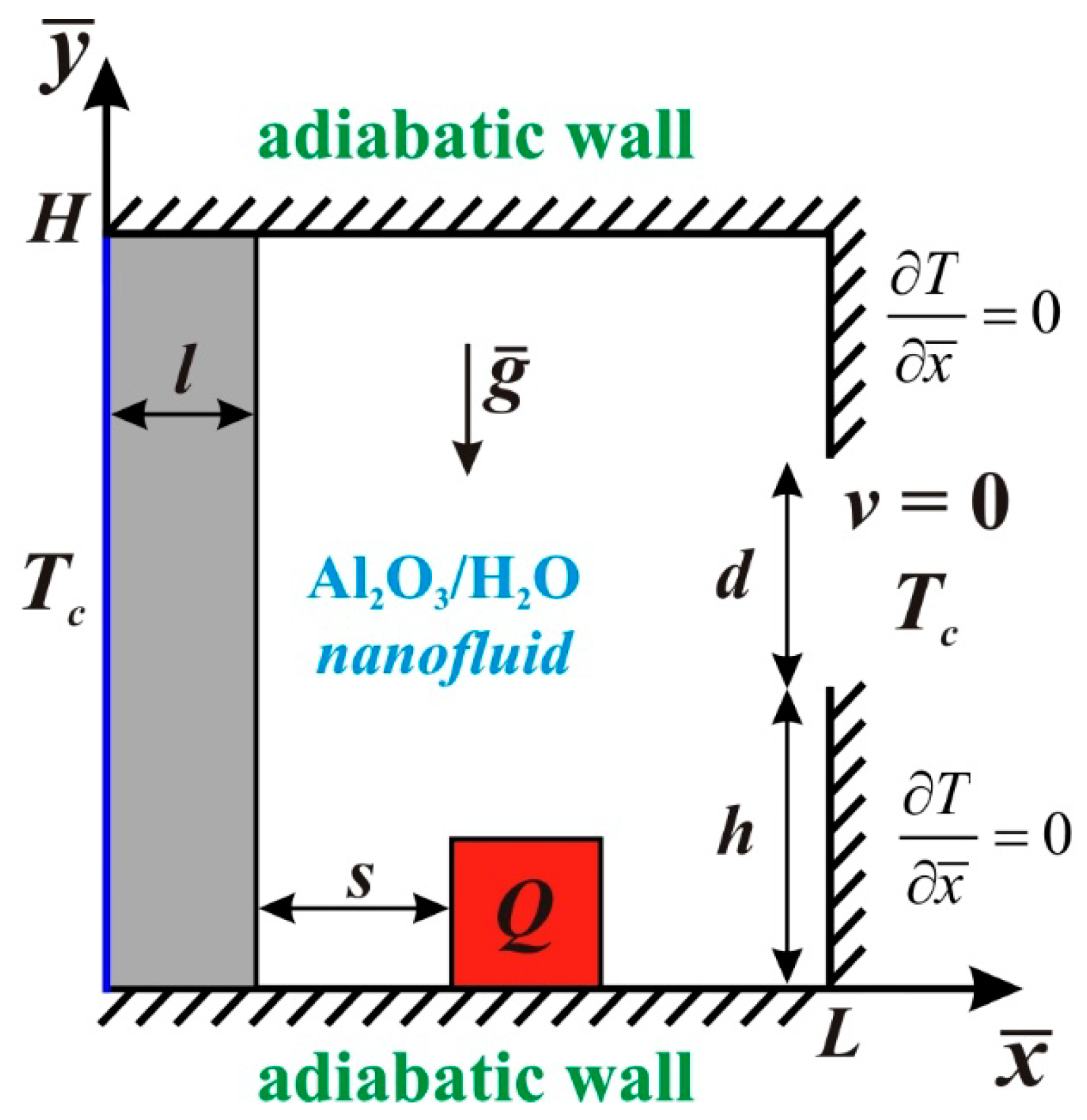
The abovementioned brief review shows that the problem of heat transfer enhancement within electronic cabinets is very important and usage of nanoparticles with additional steps can help to solve such challenge. Therefore, the aim of this work is to calculate free convection thermal transmission in a partially open alumina-water nanoliquid area under the effect of vertical solid mural and local heat-generating source. The present study is devoted to development of passive cooling arrangement for heat-generating elements using the nanoliquids under the impacts of heat-conducting walls and local opening ports. The present study is a continuation of passive cooling systems analysis that was presented in the case of open inclined cavity [
20] and closed vertical chamber [
21]. Novelty of the present investigation is an examination of free convection under the combined impacts of open border, cooled solid wall of finite thickness and heat-generating element.
4. Results
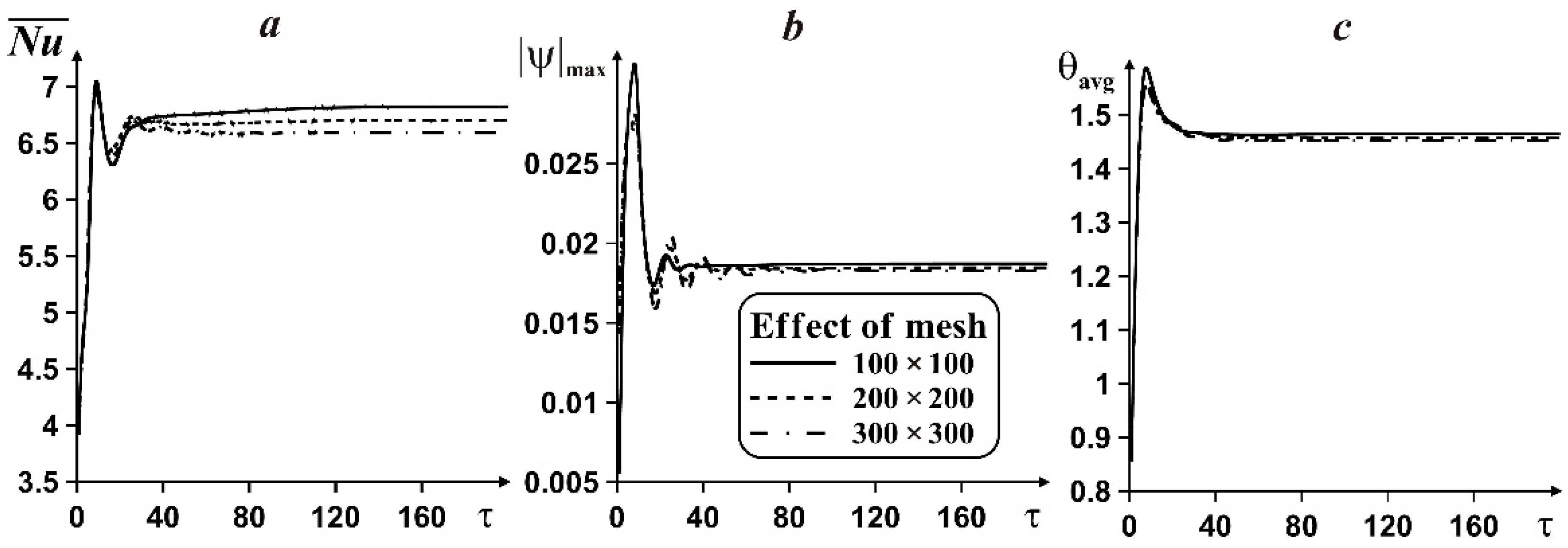
This paragraph deals with computational study of the nanoliquid circulation and heat transfer within the considered domain under the influence of the following characteristics: Rayleigh number (10
3 ≤
Ra ≤ 10
5), Prandtl number (
Pr = 6.82), thermal conductivity ratio (1 ≤
Kr =
kw/
kf ≤ 20), heater location (0.1 ≤
δ =
s/
L ≤ 0.5) and nanoparticles volume fraction (0 ≤
φ ≤ 0.04) for
h/
L = 0.2,
l/
L = 0.1 and
d/
L = 0.5. The analysis pays attention in the description of
Ra,
Kr, heater location and nanoparticles concentration impacts. Isolines of stream function and temperature,
, nanoliquid circulation rate and mean heater temperature for various control characteristics are pictured in
Figure 3,
Figure 4,
Figure 5,
Figure 6,
Figure 7,
Figure 8,
Figure 9,
Figure 10,
Figure 11 and
Figure 12. It is worth noting that such investigation can help to understand the nanoliquid behavior and heat transfer performance within the considered partially open cavity with the heat-conducting solid wall and heat-generating silicon element.
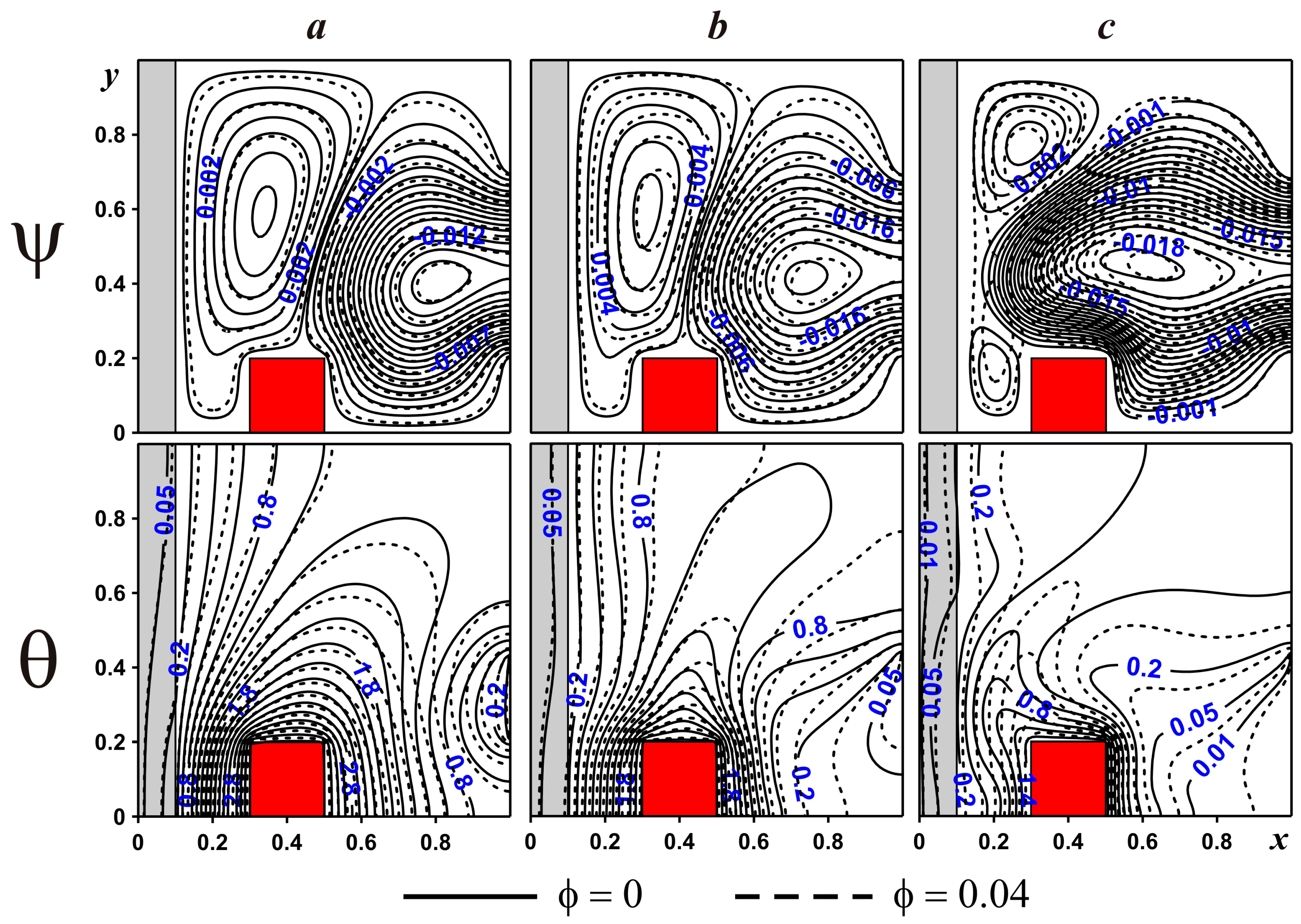
Figure 3 presents isolines of stream function and temperature within the considered region for
Kr = 5,
δ = 0.2 and various
Ra. For the present study an increase in
Ra is related to a raise of the internal heater generation
Q.
In the case of low and moderate
Ra (10
3 and 10
4) one convective cell is formed near the internal surface of the heat-conducting solid wall and another one characterizes an intrusion of cold nanoliquid from the open port inside the region. An appearance of the convective cell near the solid wall is explained by the formation of temperature difference between the cold solid border and hot heat-generating element. Therefore, this circulation reflects a counter-clockwise motion of nanofluid. Moreover, the penetrative flow from the open border begins to interact with the abovementioned vortex and the line of such interaction corresponds to the thermal plume appeared above the heat source. A growth of the internal heat generation leads to a deformation of the vortex near the solid wall due to more intensive penetrative flow. For
Ra = 10
5 (
Figure 3c) this convective cell is divided into two recirculations located in top and lower parts of the solid wall. Isotherms reflect a distribution of temperature within the region and solid wall. Heating occurs from the element located on the bottom wall, while cooling occurs from outside near the left solid border and from the open part of the right boundary. For
Ra = 10
3 (
Figure 3a) the dominated thermal transmission mode is a thermal conduction and as a result the isotherms are parallel to the heated and cooled elements. Moreover, more essential cooling occurs in the upper part of the left vertical wall due to less intensive heating from the heater. It is interesting to note that the heat-generating element is a solid block and heat conduction Equation (10) is solved within this element, but isotherms are not presented inside the heater. The main reason for such behavior is the high value of silicon thermal conductivity as the heater material in comparison with the thermal conductivity of working medium. As a result, this element is heated quickly.
An increment in the temperature difference (
Ra = 10
4 in
Figure 3b) leads to more essential cooling from the cold parts and heating from the element with intensification of convective thermal transmission in the central part of the domain. It is worth noting here that thermal plume is more essential with pronounced plume’s shape. Due to the prevalence of thermal conduction in a spacing between the solid border and heated element, heating of the solid wall occurs in the bottom part from the heater. While for high value of
Ra (10
5 in
Figure 3c) heating of the solid wall from the heater occurs in the bottom part but over the wall from the tilted thermal plume due to the convective thermal transmission intensification. A growth of
Ra results also in more essential cooling from the open port. It is worth noting, that distortion of thermal plume for
Ra = 10
5 occurs owing to the significant impact of penetrative nanoliquid on convective flow over the heater.
An inclusion of alumina nanosized particles to the clear water results in the small changes for the thermal conduction dominated mode (
Ra = 10
3 in
Figure 3a), while for convective heat transfer, cooling of the cavity occurs essentially owing to high magnitude of the effective heat-transfer capacity (see ref. [
22]).
Impacts of
Ra and
φ on the mean parameters are shown in
Figure 4. The presented parameters have been normalized using the temperature difference that depends on the volumetric heat generation. Therefore, for comparison between different Rayleigh numbers it is necessary to normalize using the general scale. An increase in the temperature difference results in an essential rise of
owing to more intensive circulation of the working liquid. While a raise of
φ results in a diminution of
. The nanoliquid circulation rate
increases with
Ra, due to more intensive circulation for high Δ
T. An increment of nanoparticles volume fraction reduces
also due to a rise of the nanofluid viscosity. A growth of Δ
T reflects a rise of θ
avg using the normalization with general scale. An enhancement of
φ allows decreasing the average temperature for heat conduction regime (
Ra = 10
3), while for the transition heat transfer (
Ra = 10
4) and heat convection (
Ra = 10
5) θ
avg increases with the nanoparticles concentration.
Figure 5 indicates the impacts of
Kr between solid border material and host fluid on isolines of stream function and temperature for
Ra = 10
5,
δ = 0.2. Regardless of the thermal conductivity ratio values, two recirculations are appeared close to the solid boundary in the upper and bottom parts, while major circulation appears from the open port. An enhancement of the solid border heat-transfer capacity results in an intensification of recirculations near the solid wall due to more intensive cooling of this wall, where cold temperature is transported intensively from the external surface till internal one and temperature gradient at this internal surface increases. The latter characterizes an intensification of convective flow near this wall that can deform the nanofluid penetration flow from the open border. Essential cooling of the heat-conducting solid wall can be found in
Figure 5 with distributions of isotherms. An increment of isothermal lines density close to the solid-fluid interface (
x = 0.1) illustrates an origin of strong temperature gradient at this wall. More significant temperature differences are found along the right and top surfaces of the local heater owing to a reciprocal action between hot and cold temperature waves. Addition of nanoparticles reflects a formation of more stable circulation close to the left solid border, where for
Kr ≥ 5 one can find alone convective cell, while for
φ = 0 we have two different circulations in upper and bottom parts. As a result, it is possible to conclude that a growth of thermal conductivity ratio related with an increment of solid wall thermal conductivity leads to an intensification of convective recirculation near the upper part of the internal surface of this heat-conducting wall owing to high cooling rate from the border
x = 0.
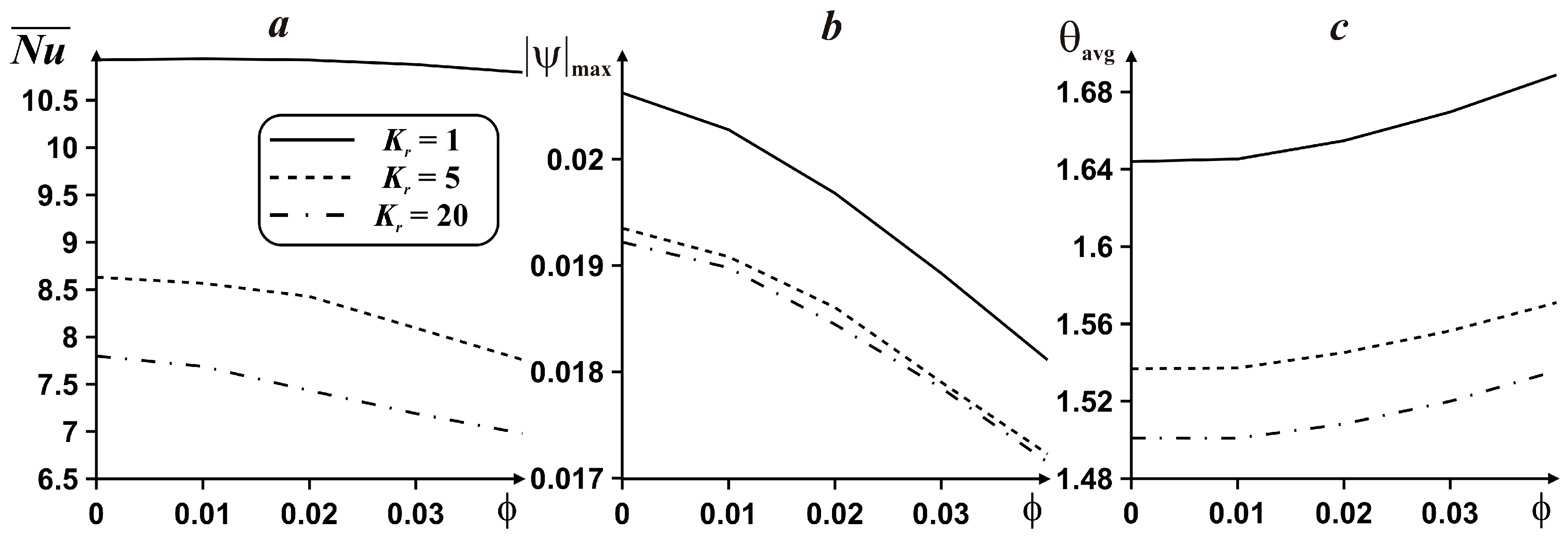
Figure 6,
Figure 7 and
Figure 8 present the effects of
Kr,
φ and
Ra on the integral parameters such as
,
and θ
avg for
δ = 0.2. As can be found from this figure, impacts of
Ra and nanoparticles concentration were described in
Figure 4. Within the considered
Figure 6,
Figure 7 and
Figure 8 the particular efforts were devoted to the influence of thermal conductivity ratio and mutual effects of all considered parameters. In the case of
Ra = 10
3 (
Figure 6) a raise of
Kr results in a diminution of all considered parameters, while all these parameters decrease with
φ also. Significant diminution for
,
and θ
avg is between
Kr = 1 and
Kr = 5, while for
Kr ∈ (5, 20) changes are not so essential. As it has been mentioned above for
Figure 4, an increase in
φ can decrease θ
avg for
Ra = 10
3.
For
Ra = 10
4 (
Figure 7) and
Ra = 10
5 (
Figure 8) the behavior of the considered parameters with
Kr is similar to the case of
Ra = 10
3 (
Figure 6), but the main differences are the values of these characteristics. For these
Ra, an increment of
φ characterizes an enhancement of the heater average temperature that does not allow to improve the cooling arrangement. Moreover, for high
Ra a transition between
Kr = 5 and
Kr = 20 becomes insignificant.
An influence of heater location on isolines of stream function and temperature for
Ra = 10
5,
Kr = 5 is demonstrated in
Figure 9. A displacement of the heater from the left wall to the right one results in a combination of two recirculations placed in top and bottom part of the domain close to the solid wall and this combined vortex becomes more stable and strong when heater locates near the right vertical border. At the same time, such displacement characterizes a deformation of the penetrative flow from the open port. It is interesting to note that initially for
δ = 0.1 (
Figure 9a) the power of the upper circulation is high in comparison with the bottom one, while a rise of
δ leads to a strengthening of the bottom vortex and an attenuation of the upper one.
For
δ = 0.3 (
Figure 9c), after a combination of these circulations, we have a convective circulation with two cores and the following increase in
δ reflects a growth of the intensity and size of the bottom convective core. Such variations of hydrodynamics are related with modification of temperature field. A presence of penetrative cold flow from the open port characterizes an origin of tilted thermal plume above the heat source. The heating effect of the solid wall from the heater becomes insignificant with an increment of distance between the heat source and solid border. Such feature characterizes a strengthening of the convective circulation appeared near the solid wall. An inclusion of alumina nanoparticles characterizes an origin of combined convective cell near the solid boundary for less value of the length between the heat source and solid border (
δ = 0.2) and for
δ = 0.5 sizes of this vortex become more powerful in comparison with the case of clear base fluid. Heat conduction effect can be found in the heat-generating element for δ = 0.1 and δ = 0.3 due to more essential interaction between the cooling temperature waves from the solid wall and open port. It is interesting to note a displacement of the heating zone inside the solid wall from the bottom part (for δ = 0.1) along the vertical coordinate owing to the impact of the tilted thermal plume.
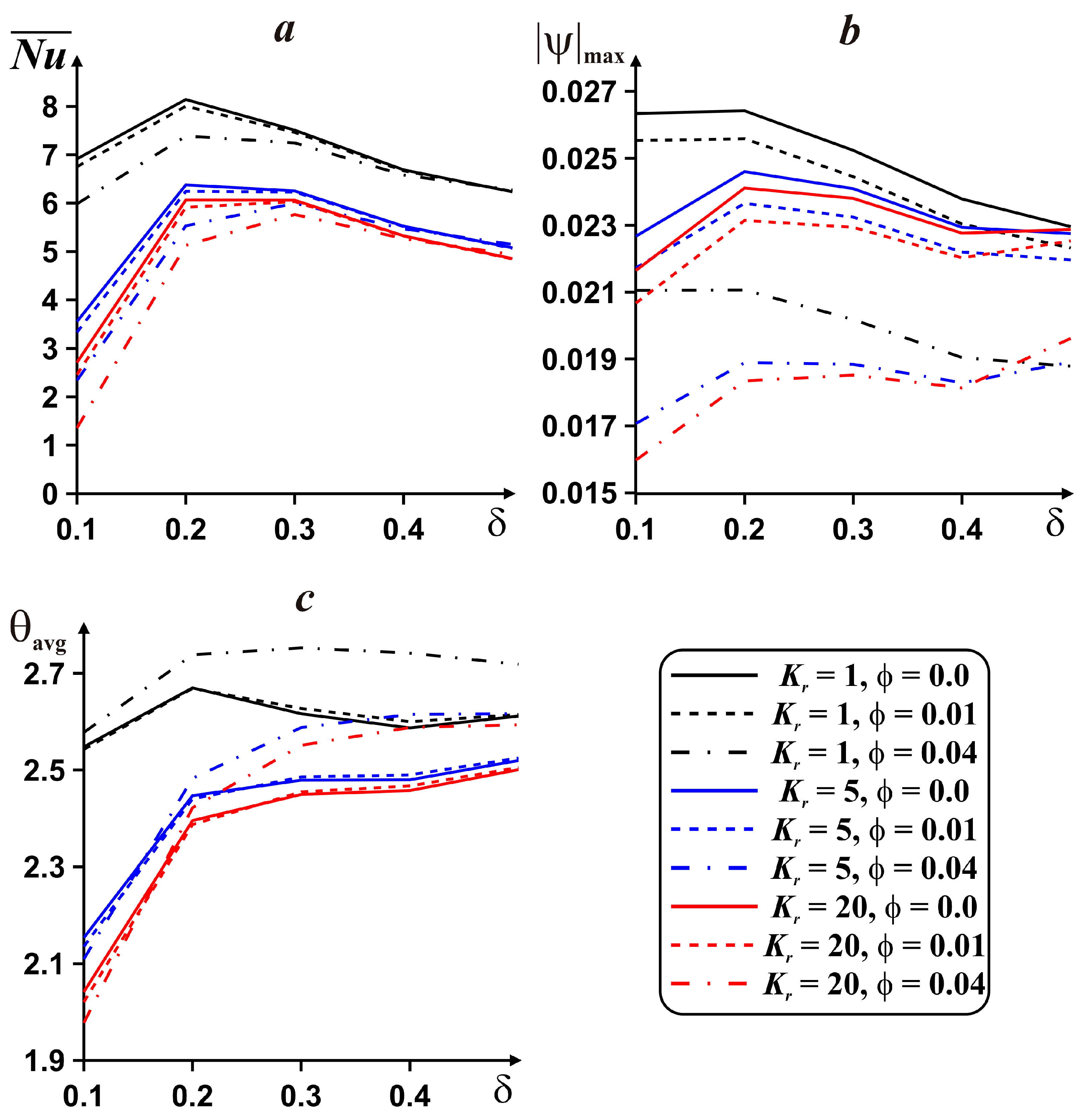
Figure 10,
Figure 11 and
Figure 12 illustrate the effects of heater location, thermal conductivity ratio, nanoparticles concentration and Rayleigh number on the average Nusselt number, nanoliquid circulation rate and heater average temperature.
In the case of heat conduction dominated regime (
Ra = 10
3 in
Figure 10), a rise of the length between the solid border and heat source results in an increment of
and this increment is significant for low values of
δ, while for
δ ∈ (0.3, 0.5) the rate of
is low in comparison with the range of
δ ∈ (0.1, 0.3). Nanofluid flow rate and heater average temperature have non-monotonic behavior with
δ. In the case of
Kr = 1, a growth of
δ ∈ (0.2, 0.5) reflects a reduction of
, while for
Kr = 5 and
Kr = 20
increases with
δ. The average heater temperature enhances with
δ for
δ ∈ (0.1, 0.4) and for
δ > 0.4 it decreases. An enhancement of the thermal conductivity ratio results in a diminution of all considered parameters. The impact of nanoparticles concentration is non-linear for
, namely,
reduces with
φ for
δ ∈ (0.1, 0.33) and it increases for other values of
δ. At the same time,
and θ
avg are diminished with
φ. It is interesting to note the negative values of the average Nusselt number for
Kr = 20. It means that the temperature gradient along the heater surface is negative due to change of the heat flux direction.
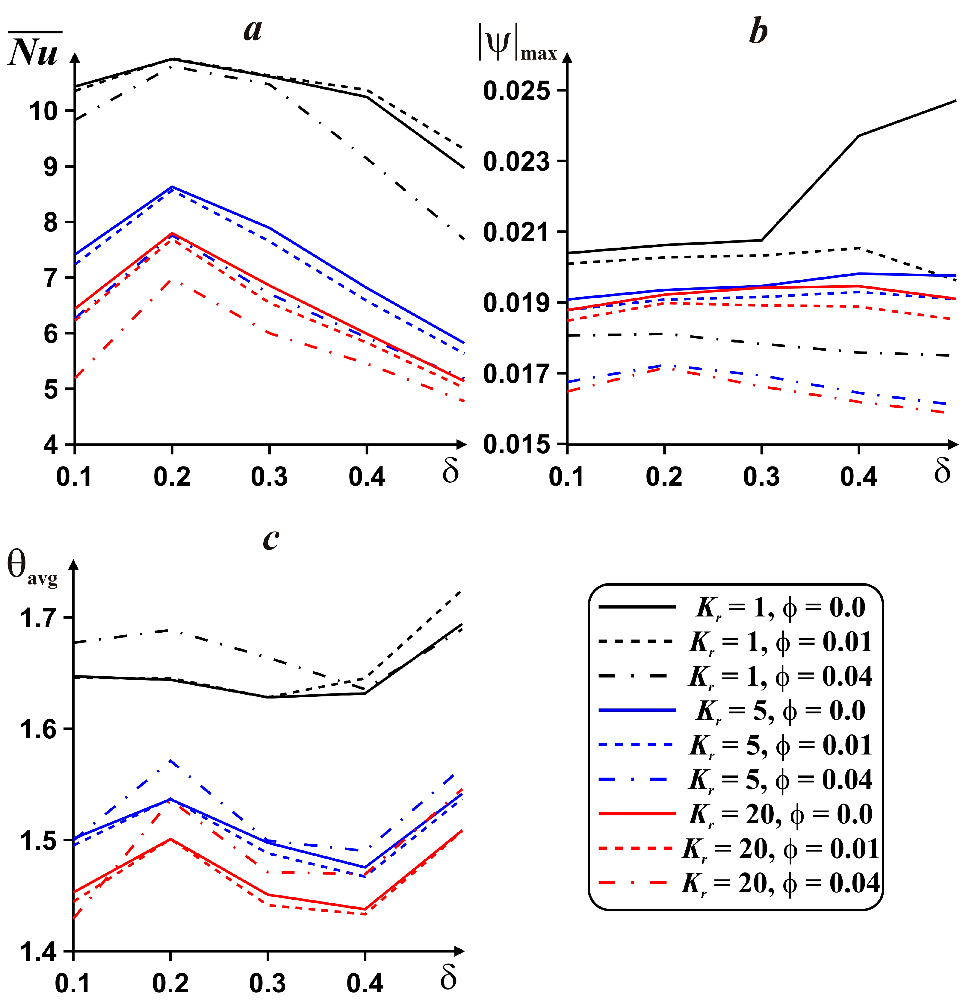
A non-linear influence of
δ on all considered parameters can be found for
Ra = 10
4 (see
Figure 11), namely, for
δ ∈ (0.1, 0.2)
and
are increased, while for
δ ∈ (0.2, 0.5) these parameters are reduced. θ
avg increases with
δ for
Kr = 5 and
Kr = 20, while for
Kr = 1 it has a non-linear behavior. An effect of
Kr on the considered parameters is the same like for
Ra = 10
3 (see
Figure 10).
and
are decreased with the nanoparticles volume fraction, while the average heater temperature is changed non-linear with
φ.
Behavior of
with all considered parameters for
Ra = 10
5 (see
Figure 12) is similar to the case of
Ra = 10
4 (see
Figure 11), while the nanoliquid circulation rate and mean heater temperature have the specific behavior.


