Experimental Study on the Evaporation and Condensation Heat Transfer Characteristics of a Vapor Chamber

1
School of Engineering Technology, Purdue University, West Lafayette, IN 47906, USA
2
School of Hydraulic, Energy and Power Engineering, Yangzhou University, Yangzhou 225127, China
3
Jiangsu Key Laboratory of Micro and Nano Heat Fluid Flow Technology and Energy Application, School of Environmental Science and Engineering, Suzhou University of Science and Technology, Suzhou 215009, China
4
Key Laboratory of Energy Thermal Conversion and Control of Ministry of Education, School of Energy and Environment, Southeast University, Nanjing 210096, China
*
Author to whom correspondence should be addressed.
Energies 2019, 12(1), 11; https://doi.org/10.3390/en12010011
Submission received: 19 November 2018
/
Revised: 11 December 2018
/
Accepted: 14 December 2018
/
Published: 21 December 2018
(This article belongs to the Special Issue Heat Transfer Enhancement)
Abstract
:A vapor chamber can meet the cooling requirements of high heat flux electronic equipment. In this paper, based on a proposed vapor chamber with a side window, a vapor chamber experimental system was designed to visually study its evaporation and condensation heat transfer performance. Using infrared thermal imaging technology, the temperature distribution and the vapor–liquid two-phase interface evolution inside the cavity were experimentally observed. Furthermore, the evaporation and condensation heat transfer coefficients were obtained according to the measured temperature of the liquid near the evaporator surface and the vapor near the condenser surface. The effects of heat load and filling rate on the thermal resistance and the evaporation and condensation heat transfer coefficients are analyzed and discussed. The results indicate that the liquid filling rate that maximized the evaporation heat transfer coefficient was different from the liquid filling rate that maximized the condensation heat transfer coefficient. The vapor chamber showed good heat transfer performance with a liquid filling rate of 33%. According to the infrared thermal images, it was observed that the evaporation/boiling heat transfer could be strengthened by the interference of easily broken bubbles and boiling liquid. When the heat input increased, the uniformity of temperature distribution was improved due to the intensified heat transfer on the evaporator surface.
1. Introduction
Vapor–liquid phase change has always been of great interest in a wide range of technical applications, such as electronic cooling [1,2], chemical processes [3,4], space thermal control [5,6], microfluidic preparation [7,8], biomedical engineering [9,10], etc. As a typical technical application, a vapor chamber is recognized as one of the most effective ways to achieve uniform heat dissipation in a confined space due to its good temperature uniformity, flexible system compatibility, and high thermal transport capacity [11,12]. Therefore, this advanced technology has been successfully applied in waste heat recovery [13], solar thermal utilization [14], thermal management of data centers [15], electronic component cooling [16], etc. Especially with the continuous development of micro-electro-mechanical systems technology [17,18], electronic components have shown a trend of miniaturization, modularization, and high power, which requires higher heat dissipation capabilities for cooling devices [19,20,21].
At present, considerable research has been carried out to develop vapor chambers with high heat transfer capacities and small volumes. For example, Liu et al. [22] proposed a high thermal performance vapor chamber with a leaf-vein-like wick structure and a thermal resistance of about 0.06 °C/W. Liu et al. [23] found that the boiling and condensation of a vapor chamber can be enhanced by inserting copper foam into the cavity. Tang et al. [24] designed a vapor chamber with multi-arteries where a heat flux of 300 W/cm2 can be achieved without reaching capillary or boiling limits, showing good heat transfer performance. In addition, it was also found that the introduction of hybrid evaporator wicks can effectively improve the heat transfer performance of vapor chambers [25,26]. Wong et al. [27] designed a new type of vapor chamber with a corrugated channel condenser surface. Their research indicated that the corrugation channels not only enlarged the condenser area, but also provided a shortcut for the backflow path. As a result, the vapor chamber exhibited satisfactory heat transfer performance. Peng et al. [28,29] conducted a heat transfer performance test on a vapor chamber with a leaf-vein-like fractal wick structure. The results demonstrated better temperature uniformity and smaller thermal resistance compared with traditional vapor chambers. Furthermore, Yao et al. [30] reported that the thermal performance of a vapor chamber under reversed gravity can be efficiently improved when a mesh wick and tree-like grooves are configured to the vapor chamber.
A prerequisite for the development of a high-performance vapor chamber is understanding the behaviors of vapor-liquid two-phase flow and boiling, evaporation, and condensation processes [31,32,33,34,35,36]. Hsieh et al. [37] investigated the effects of heat input and working temperature on the heat transfer coefficients and the thermal resistance of a vapor chamber. The results showed that the condensation and evaporation heat transfer coefficients increased with an increase in the heat load. Zhang et al. [38,39] analyzed the impact of the liquid filling rate, liquid level, and heat flux density on the vapor-liquid two-phase flow inside the chamber through visualization experiments, confirming the coupled condensation and evaporation/boiling phase change in a sealed space. Wu et al. [40] designed a vapor chamber with a transparent sidewall, and experimentally observed the phase change behavior inside the chamber from the startup state to the quasi-steady state. The research has established an intrinsic link between the working fluid state and wall temperature variation.
There have been several attempts to investigate gas–liquid phase change in a vapor chamber. It should be noted that these investigations mainly evaluate the axial heat transfer performance by the axial total heat transfer resistance, and analyze evaporation/boiling and condensation via the change of thermal resistance. In fact, the evaporation and condensation phase change in an evaporator and a condenser determine the thermal efficiency of a vapor chamber. As is known, the evaporation and condensation phase changes interact due to the confined effect of the microstructure within the vapor chamber, which can be better characterized by the boiling/condensation heat transfer coefficients than the total thermal resistance. Therefore, to a gain better understanding of the interaction between evaporation and condensation, it will be necessary to visually exhibit the fluid temperature distribution in the chamber and to evaluate heat transfer performance and boiling/condensation heat transfer coefficients inside the cavity. The thermal performance is affected by several factors, such as heat load and liquid filling rate. Until now, it remains unclear how heat load and liquid filling rate affect the temperature distribution of two-phase fluids inside a vapor chamber. In addition, to provide further insights into thermal performance, a systematic study of evaporation and condensation heat transfer inside the vapor chamber is still required.
A vapor chamber was designed with infrared (IR)-transmission glass configured on one of its walls to observe the temperature of the experimental area. Furthermore, two thermal couples were arranged in the cavity to measure the temperature of the liquid working medium near the evaporator surface, as well as the vapor temperature near the condenser surface. In this way, the interaction between the evaporation/boiling and condensation systems within a closed space was studied according to the observed vapor-liquid two-phase behaviors. Moreover, the impact of the heat load and liquid filling rate on the heat transfer coefficient was analyzed and discussed to reveal the internal relationship between boiling and condensation.
2. Experiment Methodology
2.1. Experimental System
Figure 1 visualizes the experimental system of the vapor chamber. The system contains various components, including: the vapor chamber with a side window (as shown in Figure 2); a copper column for heat conduction; two electric heating rods for heating; a power supply; a power meter; a voltage regulator for adjusting working conditions; a constant-temperature water bath for providing cooling water; a flow meter; a charge-coupled device (CCD) camera for monitoring the flow behavior of a gas-liquid two-phase medium; a light; a data acquisition instrument for testing temperatures; and a computer. The copper block is 20 mm in diameter and 105 mm in length. The heating rod is 6 mm in diameter and 50 mm in length. The heating rods are embedded into the copper block, which is in contact with the evaporator. During the experiment, the cooling water temperature was 25 °C, the same as room temperature, and the flow rate was 80 mL/min.
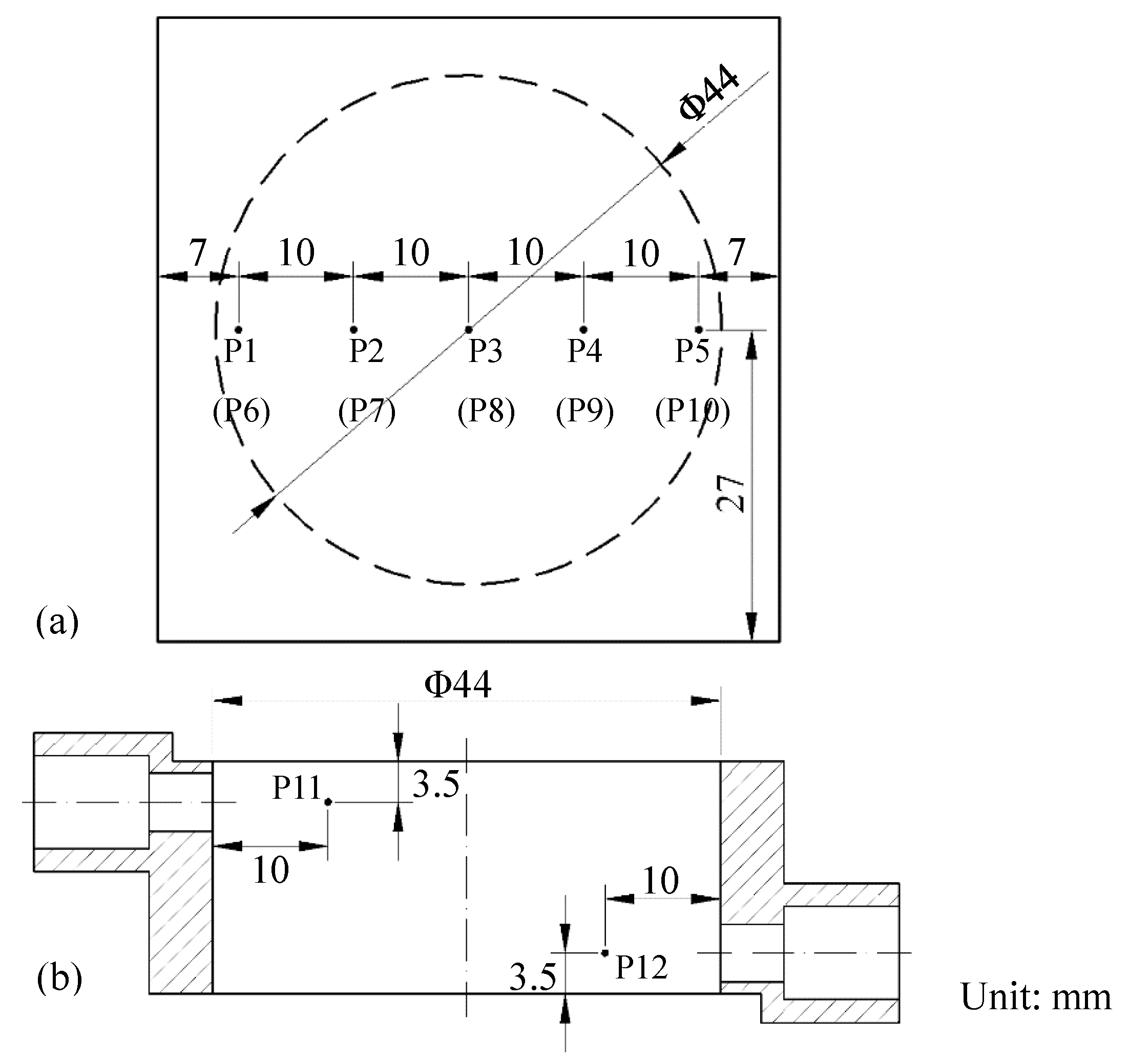
The distribution of the thermocouples in the vapor chamber are shown in Figure 3. As shown in Figure 3a, five measuring points were set from the center to the edge of the plate on both the evaporator plate and condenser plate, respectively. The positions of the thermocouples inside the cavity are shown in Figure 3b. The distance between the thermocouple temperature measuring point and the adjacent panel is 3.5 mm.
In order to reduce heat loss from the system to the surroundings, aluminum silicate fiber insulation cotton was wrapped around the copper block and the vapor chamber, leaving the circular IR-transmission glass exposed to the surroundings. Since the thermal conductivity of glass is quite low, the heat dissipation effect of the glass tube wall can be ignored. Heat loss was checked before the experiment. Based on the Fourier law, the heat input can be obtained according to the temperature distribution of the copper block. In addition, based on the energy conservation law, the heat input can also be regarded as the heat taken away by the cooling water. When the heat input calculated using the Fourier law is 88.09 W, the heat removed by water is 86.78 W. The error between them is 1.49%. This is because heating loss to the environment is inevitable even when thermal insulation measures are adopted. However, the heat loss is acceptable as it is less than 5%. Therefore, it is reasonable to assume that the experimental system is well thermally insulation.
2.2. Evaluation Index
According to the measured temperatures of the liquid near the evaporator section and the vapor near the condenser section, the heat transfer coefficients of boiling and condensation on the evaporator and condenser surfaces are determined as follows:
where q represents the heat flux, represents the evaporator surface, is the mean temperature of condenser section, and Tl and Tv are the temperature of saturated liquid and vapor, respectively.
The total thermal resistance is applied to quantitatively evaluate the thermal performance of the vapor chamber, and is defined as:
where R is the total thermal resistance; Ti,e and Ti,c are the temperature of the measuring points on the evaporator and condenser section, respectively; n is the number of measuring points; and Q is the heat input. Based on the data error analysis, the uncertainties of h1, h2, and R are 3.27%, 3.27%, and 3.17%.
3. Results and Discussion
3.1. Thermal Performance Analysis
As shown in Figure 4, the wall temperature of the evaporator and the condenser rose gradually when the heat was gradually imposed on the vapor chamber. There was a small fluctuation located at around 250 s, then the temperature tended to be stable. This phenomenon indicated that liquid remained in a static state until a certain degree of superheat was reached through the process of boiling. After that, the vapor chamber quickly went into a fully-developed boiling state. In addition, as shown in Figure 4, when the heat flux increased, the temperature of each measuring point increased and responded consistently. The temperature difference between the evaporator and the condenser also became larger with increased heat input. This can be explained by the fact that the vapor chamber was heated in the central region by a copper block that was in contact with the evaporator, which was also the main area where the liquid boiled. Thus the temperature in the center (P3) was much higher than in other areas. In addition, the vapor moved toward the center area of the condenser surface and dispersed, then the vapor condensed and released the heat. After that, the condensate flowed back to the surrounding area of the evaporator section. As a result, the temperatures at P1 and P5 (Figure 3) were the lowest due to the backflow of condensate. However, the temperature distribution of the condenser was quite uniform. Once the liquid started to boil, the vapor chamber entered a stable working state in a short time, and the heat was evenly distributed on the condenser plate.
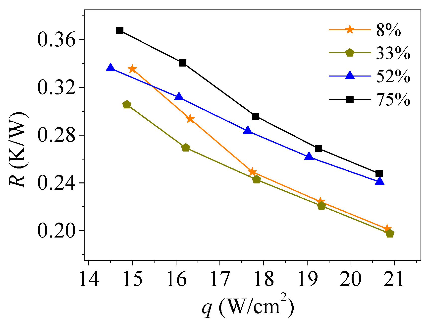
Figure 5 illustrates the total thermal resistance of the vapor chamber as affected by the liquid filling rate and heat flux. As shown, the thermal resistance decreased with the increase of heat flux for a given liquid filling rate. In other words, the thermal performance of the vapor chamber became more superior as the heat load increased. As the liquid filling rate changed from 8% to 75%, the thermal resistance decreased first and then increased. This indicates the existence of an optimal liquid filling rate that allows the vapor chamber to exhibit its best heat transfer performance. Since the heat transfer phase change includes evaporation/boiling and condensation, it is reasonable to conclude that there is indeed a certain coupling relationship between condensation and evaporation/boiling in the chamber. Within a certain range of liquid filling rate, an optimal coupling degree between evaporation/boiling and condensation can be reached.
According to Figure 5, the liquid filling rate ranged from 8% to 75% in this experiment, and the vapor chamber showed the best heat transfer performance when the filling rate was 33%, as the total thermal resistance was reduced to its minimum. It is difficult to evaluate the evaporation/boiling and condensation performance by total thermal resistance analysis. Therefore, it is necessary to further analyze the heat transfer coefficients to describe the evaporation/boiling and condensation heat transfer performance.
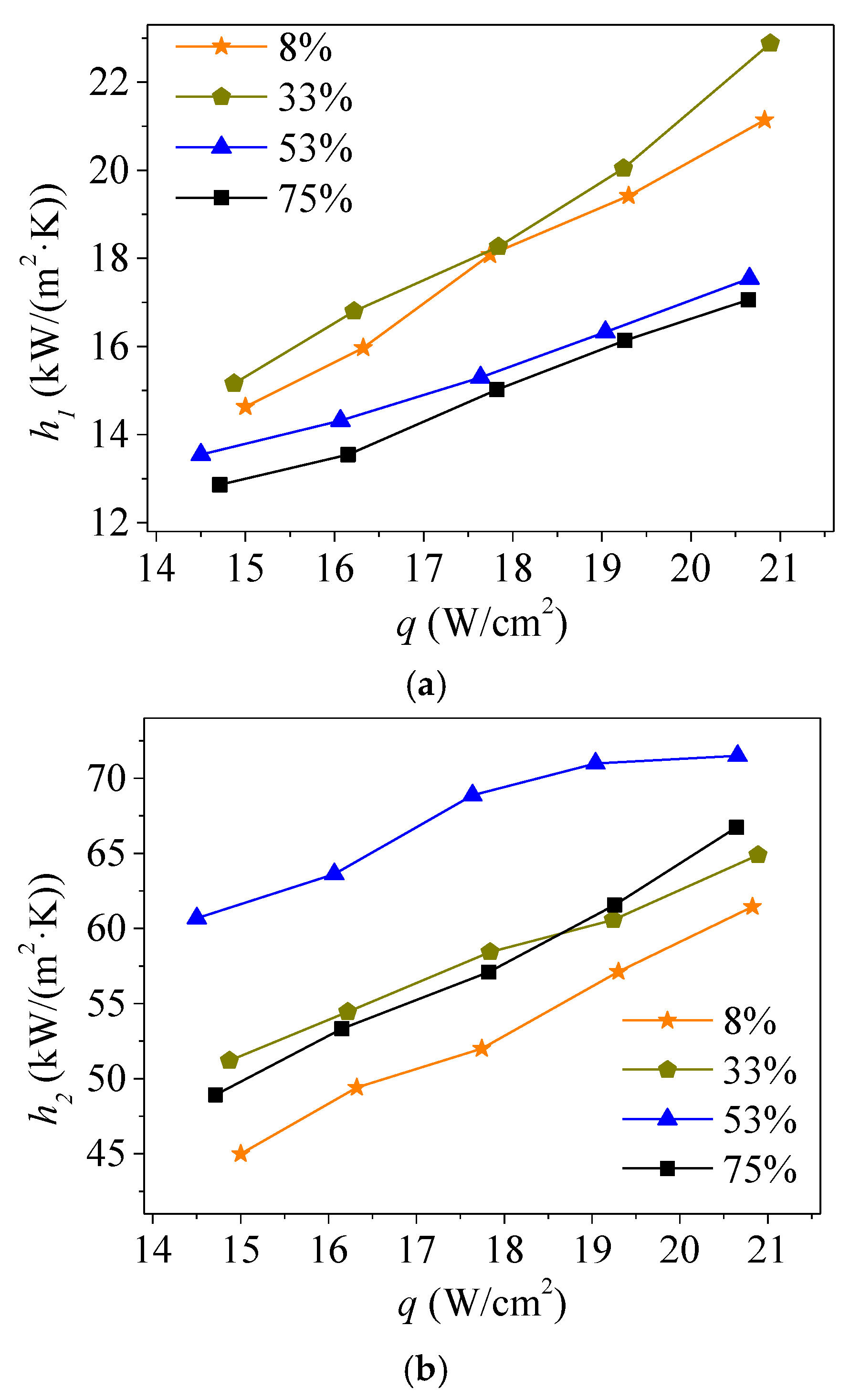
Figure 6 shows the evaporation and condensation heat transfer coefficients as a function of heat flux with different filling rates. As shown, the evaporation and condensation heat transfer coefficients increased when the heat input increased. Furthermore, as the filling rates increased, variations in the boiling heat transfer coefficient and the condensation heat transfer coefficient followed the same trend observed in the case of thermal resistance. As illustrated in Figure 6a, the evaporation heat transfer coefficient of the evaporation section reached its maximum value when the filling rate of liquid was 33%, and reached its minimum value when the rate was 75% (the highest filling rate in this experiment). When the liquid filling rate was 8%, the boiling heat transfer coefficient was between these values. This phenomenon is due to the coupled heat transfer between evaporation and boiling, as well as condensation changes that are dependent on the liquid filling rate. When the filling rate increases, the liquid height increases while the distance between the liquid surface reduces, causing different interactions between bubbles and the condensate.
As shown in Figure 6b, when the value of the condensation heat transfer coefficient reached its maximum, the liquid filling rate was 52%, instead of 33% when the boiling heat transfer coefficient reached its maximum. In this situation, the distance from the liquid surface to the condensation surface was most suitable for condensation heat transfer. As shown in Figure 7, growing bubbles carrying some boiling liquid easily made contact with the condensation surface when they were in motion. The condensate film or droplets on the condenser surface were easily broken and detached through this interference. Therefore, the condensation heat transfer could be effectively promoted. In contrast, the heat transfer coefficient of the condensation was reduced when the liquid filling rate reached 75%. Since the liquid level was higher, and the condenser surface was likely to be covered with liquid for a longer period of time, the vapor condensation on the condenser section was restricted. However, when the liquid filling rate reached 33%, there was a certain independence between the liquid surface and the condensation surface due to the low liquid level. Thus, the bubbles or the boiling liquid interfered less with the condensate, making it more difficult for the condensate to detach from the condensation surface. Moreover, the weakest interaction between condensation and evaporation/boiling phase change occurred at the 8% filling rate, where the condensate mainly relied on gravity to backflow. Therefore, the heat exchange intensity was lowest when the value of the heat transfer coefficient for the condensation section reached its minimum.
In conclusion, the vapor chamber had optimal liquid filling rates to maximize evaporation heat transfer and condensation heat transfer, respectively. It was observed that the value of the evaporation heat transfer coefficient was only about a third of the condensation heat transfer coefficient. Therefore, the main thermal resistance occurring in the vapor chamber resided in the evaporator section. The optimum liquid filling rate was 33% for evaporation phase change and 52% for condensation phase change. In this case, the vapor chamber with a liquid filling rate of 33% exhibited strong heat transfer performance, as indicated by Figure 5.
3.2. Temperature Distribution in Cavity
Figure 8 shows infrared thermal images of the cavity in the vapor chamber at different filling rates. Clearly, the temperatures of the evaporator and the condenser were different at a low filling rate. When the filling rate was in the optimized range (33%–52%), the bubbles and boiling liquid could interfere and the condensate could only cover the condenser surface for a short time, effectively promoting the detachment of the condensate from the condenser surface. Additionally, growing bubbles within the evaporator broke up more easily due to the backflow of the liquid, causing intensified disturbance of the boiling liquid. Therefore, the evaporation/boiling heat transfer was improved. In contrast, when the filling rate increased to over 75%, the boiling liquid could easily make contact with and even cover the condenser surface due to the movement of the bubble. This allowed the condensate film to become thick, which produced unfavorable conditions for condensation heat transfer.
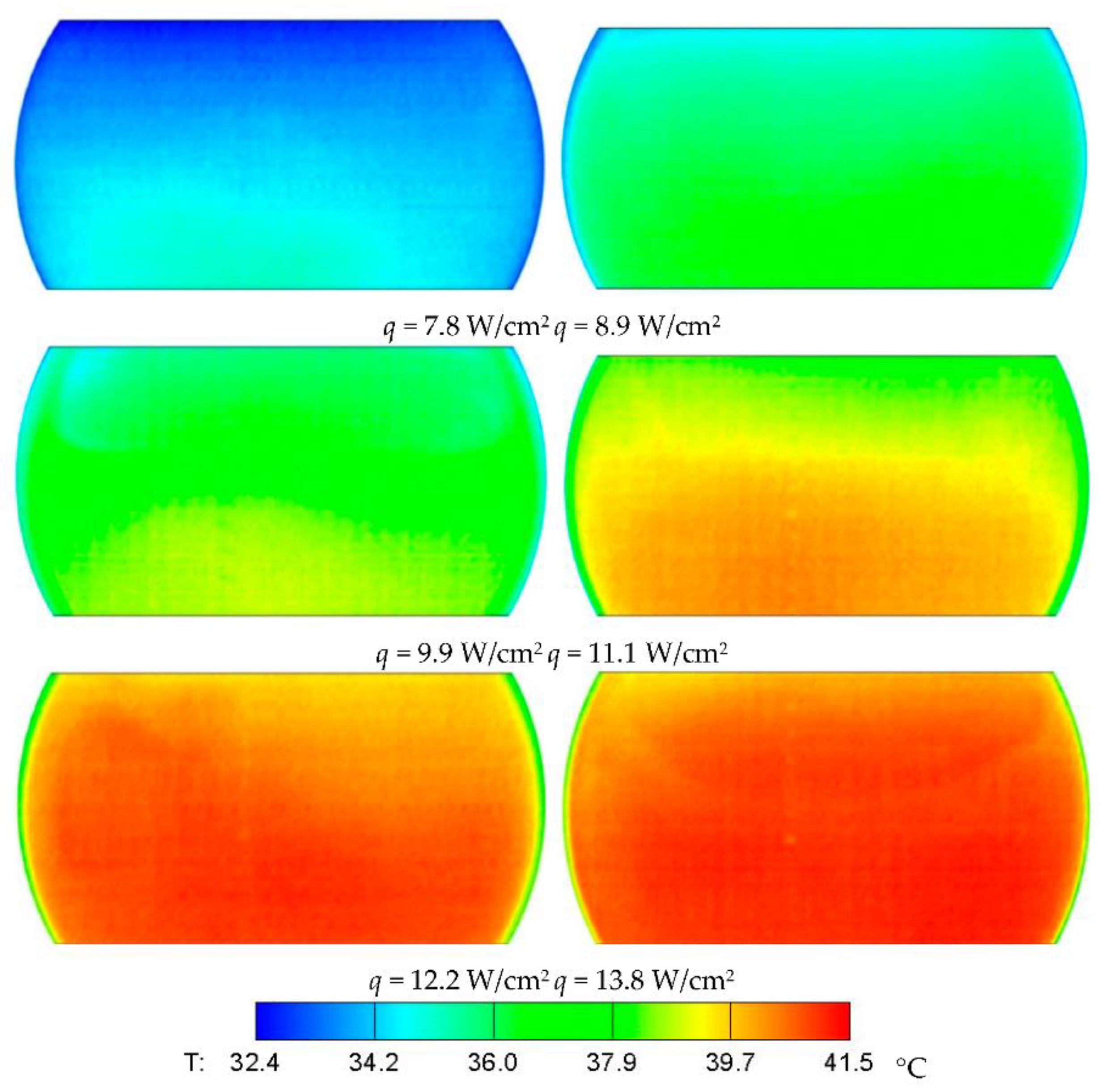
Besides the liquid filling rate, the heat input also played an important role in the heat transfer performance of the vapor chamber. Figure 9 shows infrared thermal images of the cavity of the vapor chamber under different heat inputs. The overall temperature level in the gas-liquid phase change space of the vapor chamber continued to increase with the higher heat flux. With an increase of the heat flux, the vaporization rate of the working fluid in the evaporator section increased. More bubbles were generated, and the cavity was filled with more vapor, which condensed and released heat into the condenser section. In this case, the temperature distribution in the entire gas-liquid phase change space and the condenser surface became more uniform, and the heat source could be uniformly dispersed and transmitted, which improved the heat transfer performance.
4. Conclusions
In this study, a vapor chamber with a side window was designed and a heat transfer performance testing system was conducted to visually study evaporation and condensation heat transfer within a vapor chamber. By measuring the temperature of the liquid near the evaporator section and the vapor near the condenser surface, the heat transfer coefficients of evaporation and condensation were obtained. Furthermore, the temperature distribution of the two-phase fluid inside the cavity was observed using infrared thermal imaging technology. The influence of the filling rate and heat input on the thermal resistance and boiling/condensation heat transfer coefficients were analyzed and discussed. The major conclusions are summarized as follows:
- (1)
- The optimum filling rates for the evaporation phase change and condensation phase change were different: 33% for evaporation and 52% for condensation. The condensation heat transfer coefficient was nearly triple that of evaporation under the same liquid filling rate, leading to better thermal performance of the vapor chamber with a liquid filling rate of 33%.
- (2)
- The evaporation/boiling heat transfer could be improved by promoting the detachment of the condensate from the condenser surface using the interference of easily broken bubbles and boiling liquid. In addition, a rise in heat input significantly improved the temperature distribution due to the intensified heat transfer on the evaporator surface.
- (3)
- A minimal thermal resistance value appeared as the liquid filling rate fluctuated between 8% and 75%, indicating that within a certain range of liquid filling rate, an optimal coupling degree between evaporation/boiling and condensation can be reached.
- (4)
- The evaporation/boiling heat transfer can be enhanced through the interference of easily broken bubbles and boiling liquid. According to the infrared thermal images, as the heat input increased, more uniform temperature distribution was observed due to intensified heat transfer on the evaporator surface.
Author Contributions
F.Y. provided the guidance and supervision. Y.L., X.H. and C.S. implemented the main research, discussed the results, and wrote the paper. M.Z. collected the data. All authors read and approved the final manuscript.
Funding
The research is financially supported by National Natural Science Foundation of China (Nos. 51706193 and 51876184) and Natural Science Foundation of the Jiangsu Higher Education Institutions of China (No. 17KJB470014).
Conflicts of Interest
The authors declare no conflict of interest.
References
- Green, C.; Kottke, P.; Han, X.; Woodrum, C.; Sarvey, T.; Asrar, P.; Zhang, X.; Joshi, Y.; Fedorov, A.; Sitaraman, S.; et al. A review of two-phase forced cooling in three-dimensional stacked electronics: Technology integration. J. Electron. Packag. 2015, 137, 040802. [Google Scholar] [CrossRef]
- Chen, Y.P.; Zhang, C.B.; Shi, M.H.; Wu, J.F.; Peterson, G.P. Study on flow and heat transfer characteristics of heat pipe with axial “omega”-shaped microgrooves. Int. J. Heat Mass Transf. 2009, 52, 636–643. [Google Scholar] [CrossRef]
- Attinger, D.; Frankiewicz, C.; Betz, A.R.; Schutzius, T.M.; Ganguly, R.; Das, A.; Kim, C.-J.; Megaridis, C.M. Surface engineering for phase change heat transfer: A review. MRS Energy Sustain. 2014, 1, E4. [Google Scholar] [CrossRef]
- Chen, Y.; Liu, X.; Shi, M. Hydrodynamics of double emulsion droplet in shear flow. Appl. Phys. Lett. 2013, 102, 051609. [Google Scholar] [CrossRef]
- Katzoff, S. Heat pipes and vapor chambers for thermal control of spacecraft. In Thermophysics of Spacecraft and Planetary Bodies; Heller, G.B., Ed.; Academic Press: New York, NY, USA, 1967; pp. 761–818. [Google Scholar]
- Deng, Z.; Liu, X.; Zhang, C.; Huang, Y.; Chen, Y. Melting behaviors of pcm in porous metal foam characterized by fractal geometry. Int. J. Heat Mass Transf. 2017, 113, 1031–1042. [Google Scholar] [CrossRef]
- Zhang, C.B.; Gao, W.; Zhao, Y.J.; Chen, Y.P. Microfluidic generation of self-contained multicomponent microcapsules for self-healing materials. Appl. Phys. Lett. 2018, 113, 203702. [Google Scholar] [CrossRef]
- Chen, Y.P.; Deng, Z.L. Hydrodynamics of a droplet passing through a microfluidic t-junction. J. Fluid Mech. 2017, 819, 401–434. [Google Scholar] [CrossRef]
- Wang, J.; Sun, L.; Zou, M.; Gao, W.; Liu, C.; Shang, L.; Gu, Z.; Zhao, Y. Bioinspired shape-memory graphene film with tunable wettability. Sci. Adv. 2017, 3, e1700004. [Google Scholar] [CrossRef]
- Wang, J.; Gao, W.; Zhang, H.; Zou, M.H.; Chen, Y.P.; Zhao, Y.J. Programmable wettability on photocontrolled graphene film. Sci. Adv. 2018, 4, eaat7392. [Google Scholar] [CrossRef]
- Weibel, J.A.; Garimella, S.V. Chapter four—Recent advances in vapor chamber transport characterization for high-heat-flux applications. In Advances in Heat Transfer, 1st ed.; Sparrow, E.M., Cho, Y.I., Abraham, J.P., Gorman, J.M., Eds.; Elsevier: New York, NY, USA, 2013; Volume 45, pp. 209–301. [Google Scholar]
- Jouhara, H.; Chauhan, A.; Nannou, T.; Almahmoud, S.; Delpech, B.; Wrobel, L.C. Heat pipe based systems—Advances and applications. Energy 2017, 128, 729–754. [Google Scholar] [CrossRef]
- Deng, Z.; Zheng, Y.; Liu, X.; Zhu, B.; Chen, Y. Experimental study on thermal performance of an anti-gravity pulsating heat pipe and its application on heat recovery utilization. Appl. Therm. Eng. 2017, 125, 1368–1378. [Google Scholar] [CrossRef]
- Liu, X.; Chen, Y.; Shi, M. Dynamic performance analysis on start-up of closed-loop pulsating heat pipes (clphps). Int. J. Therm. Sci. 2013, 65, 224–233. [Google Scholar] [CrossRef]
- Naphon, P.; Wiriyasart, S.; Wongwises, S. Thermal cooling enhancement techniques for electronic components. Int. Commun. Heat Mass Transf. 2015, 61, 140–145. [Google Scholar] [CrossRef]
- Ranjan, R.; Patel, A.; Garimella, S.V.; Murthy, J.Y. Wicking and thermal characteristics of micropillared structures for use in passive heat spreaders. Int. J. Heat Mass Transf. 2011, 55, 586–596. [Google Scholar] [CrossRef]
- Zhang, C.; Deng, Z.; Chen, Y. Temperature jump at rough gas–solid interface in couette flow with a rough surface described by cantor fractal. Int. J. Heat Mass Transf. 2014, 70, 322–329. [Google Scholar] [CrossRef]
- Zhang, C.; Chen, Y.; Deng, Z.; Shi, M. Role of rough surface topography on gas slip flow in microchannels. Phys. Rev. E 2012, 86, 016319. [Google Scholar] [CrossRef] [PubMed]
- Wiriyasart, S.; Naphon, P. Thermal performance enhancement of vapor chamber by coating mini-channel heat sink with porous sintering media. Int. J. Heat Mass Transf. 2018, 126, 116–122. [Google Scholar] [CrossRef]
- Zhang, C.B.; Yu, F.W.; Li, X.J.; Chen, Y.P. Gravity–capillary evaporation regimes in micro-grooves. AIChE J. 2019. [Google Scholar] [CrossRef]
- Chen, Y.; Zhang, C.; Shi, M.; Yang, Y. Thermal and hydrodynamic characteristics of constructal tree-shaped minichannel heat sink. AIChE J. 2010, 56, 2018–2029. [Google Scholar] [CrossRef]
- Liu, W.Y.; Peng, Y.; Luo, T.; Luo, Y.Q.; Huang, K.D. The performance of the vapor chamber based on the plant leaf. Int. J. Heat Mass Transf. 2016, 98, 746–757. [Google Scholar] [CrossRef]
- Liu, Z.L.; Zheng, F.W.; Li, Y.X. Enhancing boiling and condensation co-existing heat transfer in a small and closed space by copper foam inserts. Int. J. Heat Mass Transf. 2017, 108, 961–971. [Google Scholar] [CrossRef]
- Tang, Y.; Yuan, D.; Lu, L.; Wang, Z. A multi-artery vapor chamber and its performance. Appl. Therm. Eng. 2013, 60, 15–23. [Google Scholar] [CrossRef]
- Ju, Y.S.; Kaviany, M.; Nam, Y.; Sharratt, S.; Hwang, G.S.; Catton, I.; Fleming, E.; Dussinger, P. Planar vapor chamber with hybrid evaporator wicks for the thermal management of high-heat-flux and high-power optoelectronic devices. Int. J. Heat Mass Transf. 2013, 60, 163–169. [Google Scholar] [CrossRef]
- Ryu, S.; Han, J.; Kim, J.; Lee, C.; Nam, Y. Enhanced heat transfer using metal foam liquid supply layers for micro heat spreaders. Int. J. Heat Mass Transf. 2017, 108, 2338–2345. [Google Scholar] [CrossRef]
- Wong, S.-C.; Hsieh, K.-C.; Wu, J.-D.; Han, W.-L. A novel vapor chamber and its performance. Int. J. Heat Mass Transf. 2010, 53, 2377–2384. [Google Scholar] [CrossRef]
- Peng, Y.; Liu, W.; Liu, B.; Liu, J.; Huang, K.; Wang, L.; Chen, W. The performance of the novel vapor chamber based on the leaf vein system. Int. J. Heat Mass Transf. 2015, 86, 656–666. [Google Scholar] [CrossRef]
- Peng, Y.; Liu, W.; Wang, N.; Tian, Y.; Chen, X. A novel wick structure of vapor chamber based on the fractal architecture of leaf vein. Int. J. Heat Mass Transf. 2013, 63, 120–133. [Google Scholar] [CrossRef]
- Yao, F.; Miao, S.; Zhang, M.; Chen, Y. An experimental study of an anti-gravity vapor chamber with a tree-shaped evaporator. Appl. Therm. Eng. 2018, 141, 1000–1008. [Google Scholar] [CrossRef]
- Ranjan, R.; Murthy, J.Y.; Garimella, S.V.; Vadakkan, U. A numerical model for transport in flat heat pipes considering wick microstructure effects. Int. J. Heat Mass Transf. 2011, 54, 153–168. [Google Scholar] [CrossRef] [Green Version]
- Zhang, C.; Chen, Y.; Wu, R.; Shi, M. Flow boiling in constructal tree-shaped minichannel network. Int. J. Heat Mass Transf. 2011, 54, 202–209. [Google Scholar] [CrossRef]
- Patankar, G.; Weibel, J.A.; Garimella, S.V. A validated time-stepping analytical model for 3d transient vapor chamber transport. Int. J. Heat Mass Transf. 2018, 119, 867–879. [Google Scholar] [CrossRef]
- Zhang, C.; Chen, Y.; Shi, M. Effects of roughness elements on laminar flow and heat transfer in microchannels. Chem. Eng. Process. 2010, 49, 1188–1192. [Google Scholar] [CrossRef]
- Patankar, G.; Weibel, J.A.; Garimella, S.V. Patterning the condenser-side wick in ultra-thin vapor chamber heat spreaders to improve skin temperature uniformity of mobile devices. Int. J. Heat Mass Transf. 2016, 101, 927–936. [Google Scholar] [CrossRef] [Green Version]
- Zhang, C.; Chen, Y.; Wu, L.; Shi, M. Thermal response of brick wall filled with phase change materials(PCM) under fluctuating outdoor temperatures. Energy Build. 2011, 43, 3514–3520. [Google Scholar] [CrossRef]
- Hsieh, S.-S.; Lee, R.-Y.; Shyu, J.-C.; Chen, S.-W. Thermal performance of flat vapor chamber heat spreader. Energ. Convers. Manag. 2008, 49, 1774–1784. [Google Scholar] [CrossRef]
- Zhang, G.; Liu, Z.; Wang, C. An experimental study of boiling and condensation co-existing phase change heat transfer in small confined space. Int. J. Heat Mass Transf. 2013, 64, 1082–1090. [Google Scholar] [CrossRef]
- Zhang, G.; Liu, Z.; Wang, C. A visualization study of the influences of liquid levels on boiling and condensation co-existing phase change heat transfer phenomenon in small confined spaces. Int. J. Heat Mass Transf. 2014, 73, 415–423. [Google Scholar] [CrossRef]
- Wu, L.; Chen, Y.; Wu, S.; Zhang, M.; Yang, W.; Tang, F. Visualization study of startup modes and operating states of a flat two-phase micro thermosyphon. Energies 2018, 11, 2291. [Google Scholar] [CrossRef]
Figure 1.
(a) Schematic diagram of the experimental set and (b) the experimental rig.
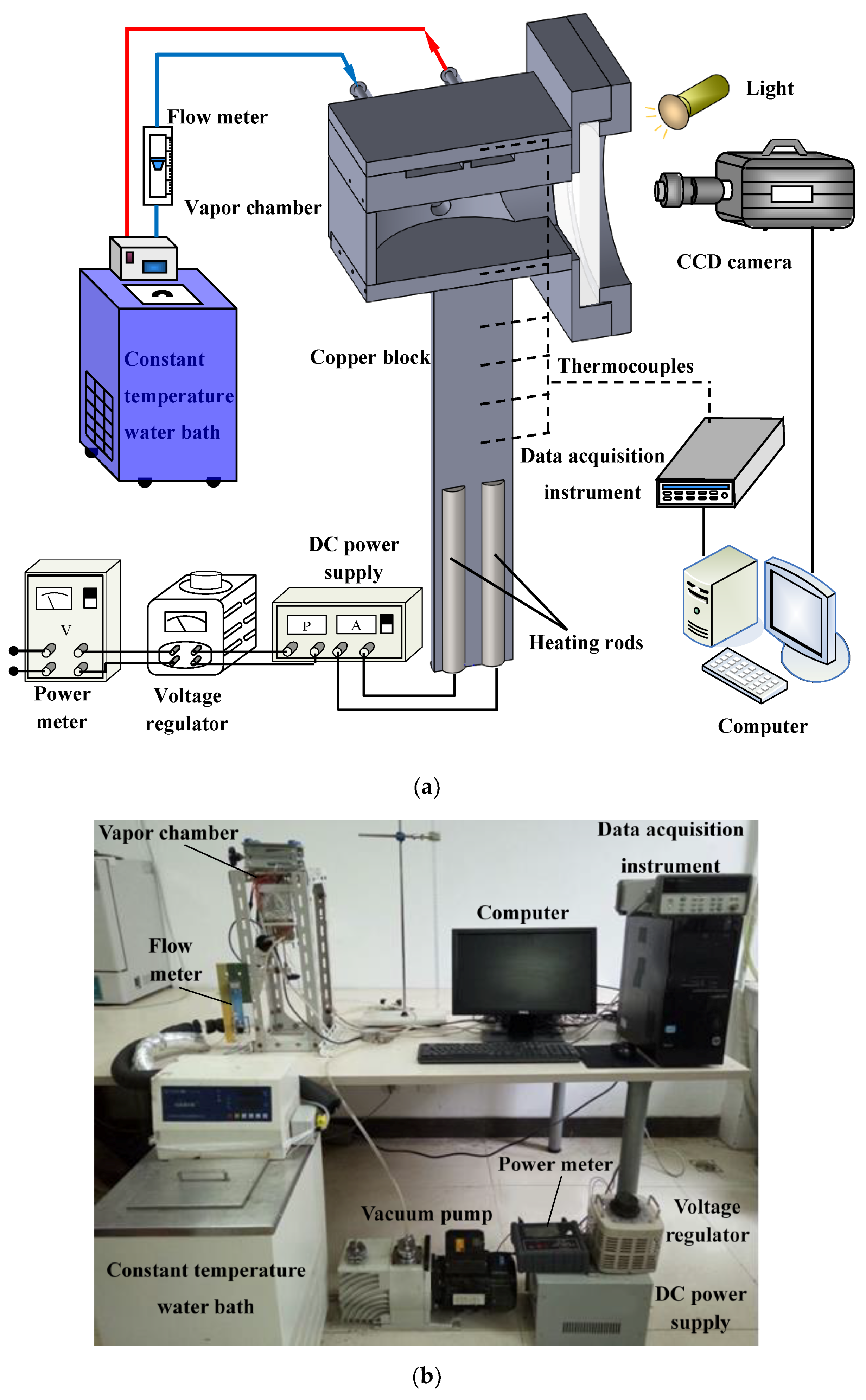
Figure 2.
Structure of vapor chamber with side window.
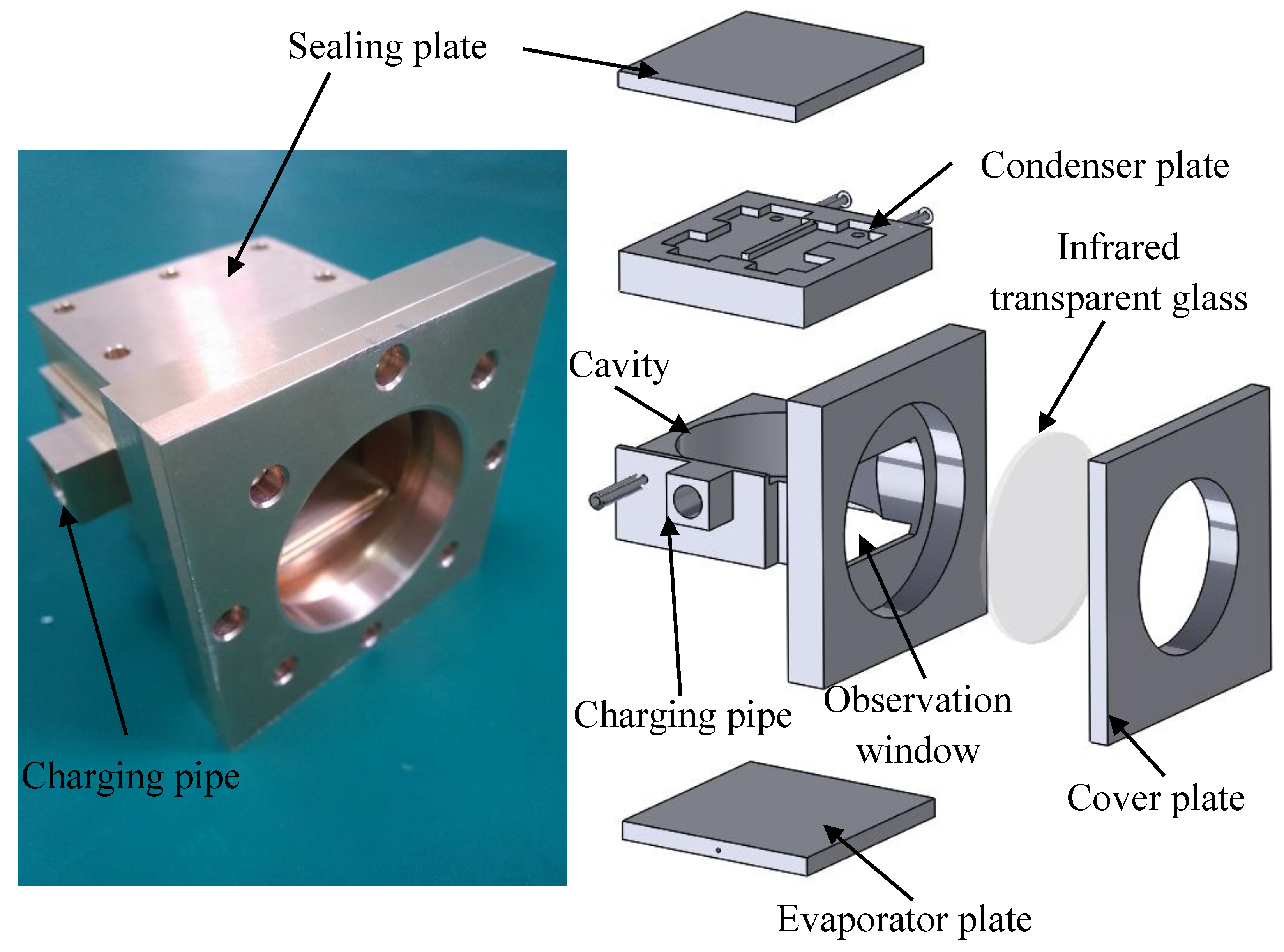
Figure 3.
Position of measuring points (a) on the evaporator (P1–P5) and condenser (P6–P10) surface and (b) in the cavity (P11, P12).
Figure 3.
Position of measuring points (a) on the evaporator (P1–P5) and condenser (P6–P10) surface and (b) in the cavity (P11, P12).

Figure 4.
Temperature dynamic variation of the evaporator and condenser walls (H = 20 mm, φ = 52%, q = 7.8 W/cm2).
Figure 4.
Temperature dynamic variation of the evaporator and condenser walls (H = 20 mm, φ = 52%, q = 7.8 W/cm2).
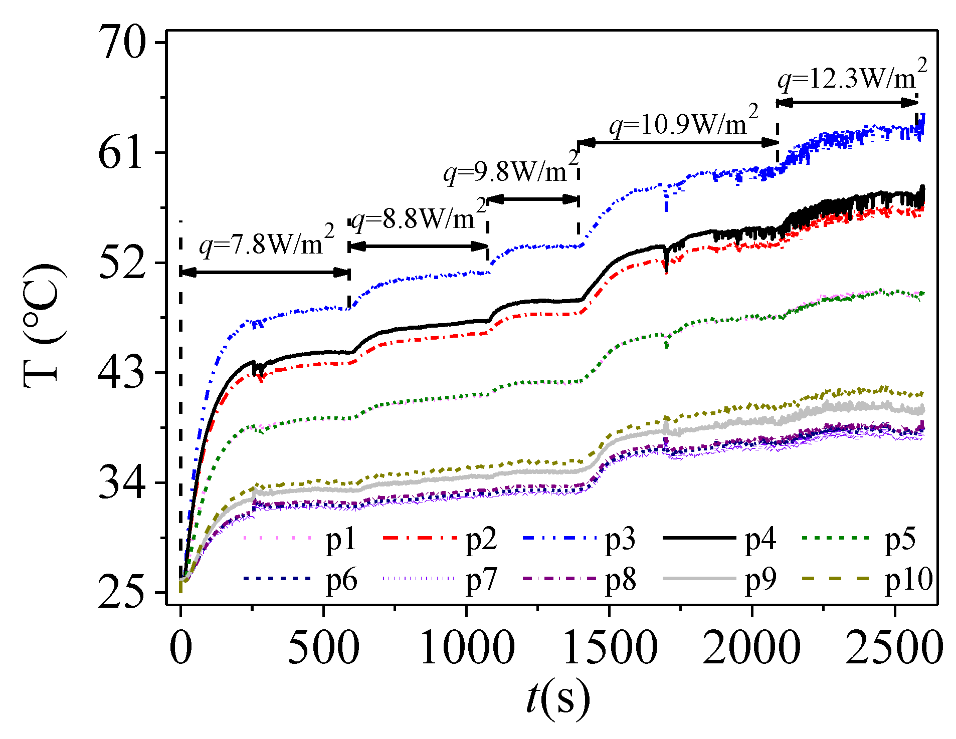
Figure 5.
Effect of filling rate on total thermal resistance (H = 20 mm).

Figure 6.
Effect of filling rate on the heat transfer coefficients: (a) evaporation heat transfer coefficient, (b) condensation heat transfer coefficient (H = 20 mm).
Figure 6.
Effect of filling rate on the heat transfer coefficients: (a) evaporation heat transfer coefficient, (b) condensation heat transfer coefficient (H = 20 mm).

Figure 7.
Images of the gas–liquid two phase flow in the cavity: (a) the interaction between bubbles and condensate (H = 20 mm; φ = 52%; q = 16.1 W/cm2; Δt = 15 ms); (b) the interaction between boiling liquid and condensate (H = 20 mm; φ = 52%; q = 19.3 W/cm2; Δt = 15 ms).
Figure 7.
Images of the gas–liquid two phase flow in the cavity: (a) the interaction between bubbles and condensate (H = 20 mm; φ = 52%; q = 16.1 W/cm2; Δt = 15 ms); (b) the interaction between boiling liquid and condensate (H = 20 mm; φ = 52%; q = 19.3 W/cm2; Δt = 15 ms).
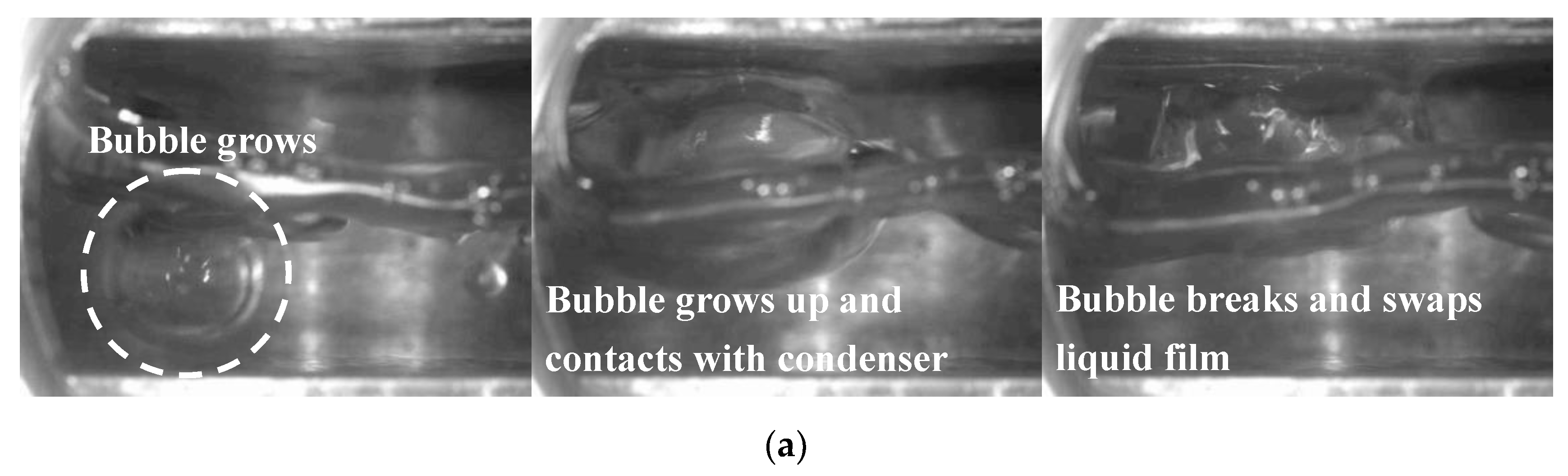

Figure 8.
Infrared thermal images of the vapor chamber at different filling rates (q = 17.7 W/cm2, H = 20 mm).
Figure 8.
Infrared thermal images of the vapor chamber at different filling rates (q = 17.7 W/cm2, H = 20 mm).

Figure 9.
Infrared thermal images of the vapor chamber under different heat inputs (φ = 50%, H = 20 mm).
Figure 9.
Infrared thermal images of the vapor chamber under different heat inputs (φ = 50%, H = 20 mm).
© 2018 by the authors. Licensee MDPI, Basel, Switzerland. This article is an open access article distributed under the terms and conditions of the Creative Commons Attribution (CC BY) license (http://creativecommons.org/licenses/by/4.0/).
Share and Cite
MDPI and ACS Style
Liu, Y.; Han, X.; Shen, C.; Yao, F.; Zhang, M. Experimental Study on the Evaporation and Condensation Heat Transfer Characteristics of a Vapor Chamber. Energies 2019, 12, 11. https://doi.org/10.3390/en12010011
AMA Style
Liu Y, Han X, Shen C, Yao F, Zhang M. Experimental Study on the Evaporation and Condensation Heat Transfer Characteristics of a Vapor Chamber. Energies. 2019; 12(1):11. https://doi.org/10.3390/en12010011
Chicago/Turabian StyleLiu, Yanfei, Xiaotian Han, Chaoqun Shen, Feng Yao, and Mengchen Zhang. 2019. "Experimental Study on the Evaporation and Condensation Heat Transfer Characteristics of a Vapor Chamber" Energies 12, no. 1: 11. https://doi.org/10.3390/en12010011
Note that from the first issue of 2016, this journal uses article numbers instead of page numbers. See further details here.