Study on a Battery Thermal Management System Based on a Thermoelectric Effect

College of Mechanical Engineering, Xi’an University of Science and Technology, Xi’an 710054, China
*
Author to whom correspondence should be addressed.
Energies 2018, 11(2), 279; https://doi.org/10.3390/en11020279
Submission received: 27 December 2017
/
Revised: 12 January 2018
/
Accepted: 16 January 2018
/
Published: 24 January 2018
(This article belongs to the Special Issue The International Symposium on Electric Vehicles (ISEV2017))
Abstract
:As is known to all, a battery pack is significantly important for electric vehicles. However, its performance is easily affected by temperature. In order to address this problem, an enhanced battery thermal management system is proposed, which includes two parts: a modified cooling structure and a control unit. In this paper, more attention has been paid to the structure part. According to the heat generation mechanism of a battery and a thermoelectric chip, a simplified heat generation model for a single cell and a special cooling model were created in ANSYS 17.0. The effects of inlet velocity on the performance of different heat exchanger structures were studied. The results show that the U loop structure is more reasonable and the flow field distribution is the most uniform at the inlet velocity of 1.0 m/s. Then, on the basis of the above heat exchanger and the liquid flow velocity, the cooling effect of the improved battery temperature adjustment structure and the traditional liquid temperature regulating structure were analyzed. It can be seen that the liquid cooling structure combined with thermoelectric cooling demonstrates a better performance. With respect to the control system, the corresponding hardware and software were also developed. In general, the design process for this enhanced battery thermal management system can provide a wealth of guidelines for solving similar problems. The H commutation circuit, matrix switch circuit, temperature measurement circuit, and wireless communication modules were designed in the control system and the temperature control strategy was also developed.
1. Introduction
Environmental pollution and the energy crisis are becoming more and more serious, so all countries are focusing on renewable energy. As a typical representative of the renewable energy industry, electric vehicles have attracted worldwide attention due to their cleanness. However, the function of an electric vehicle is restricted by its power battery [1,2,3,4]. It has been found that the battery life and work efficiency are the highest when the operating temperature of the lithium battery is in the range of 25–45 °C. Unfortunately, the temperature of the power battery often is not kept in the best range during actual operation. The internal resistance of the battery will rise sharply when the operating temperature is lower than 0 °C, which can greatly influence the performance of the battery. On the other hand, the speed of the battery’s side reaction will accelerate when the temperature is too high, and the capacity of the battery will be greatly reduced. A battery fire, explosion, or other safety incidents can also happen due to a high temperature [5,6,7].
In terms of the thermal mechanism of the battery, experts have studied the heat production model of the lithium-ion battery positively. The heat generation model of the battery can be divided into an electrochemical thermal coupling model and an electrothermal coupling model according to the principle of electrochemistry. Smith et al. [8] simulated the temperature field of the battery using a one-dimensional model and pointed out that the contact resistance heat, joule heat, and electrochemical reaction heat are the most important three parts of the heat production of the battery. However, the internal heat production during the charging and discharging process of battery charging is extremely complex. In order to establish accurate heat generation models, all kinds of reactive heat and Joule heat caused by different electrochemical reaction rates and an uneven distribution of internal electric current at different charging/discharging times and different battery temperatures should be studied. Gao et al. [9] proposed a coupled equivalent circuit and convective thermal model to determine the state-of-charge (SOC) and temperature of a LiFePO4 battery working in a real environment. Chiew et al. [10] studied the battery’s thermal wrap and analyzed the thermal effect of latent heat storage. Now, the widely recognized model for the heating effect is to treat a lithium ion battery as a uniform internal heat source. The transport equation of conservation and energy, reasonable boundary conditions, and initial conditions are established to obtain the internal and external temperature distribution of the battery [11].
The battery’s thermal management mainly has three methods: air adjustment, liquid adjustment, and phase change material adjustment. Chen et al. [12,13] studied the air condition of the battery’s thermal management system and optimized the angles of the plenums. The results showed that changing the angles of the plenums is one of the most effective approaches. Yu et al. [14] designed a battery thermal management system that contained both serial ventilation cooling and parallel ventilation cooling. The maximum temperature of the novel cooling system was reduced and the temperature uniformity was improved compared to the traditional system. The air conditioning method has advantages such as simple operation and a small cost, while the temperature regulating efficiency is low. Once the discharge current exceeds 30 A, the air cooling will not reach the heat dissipation requirement of the battery [15]. Therefore, the medium of the thermostat system is changed to improve the efficiency of the temperature adjustment. Yuan et al. [16] studied the liquid temperature control scheme and a uniform heating was obtained for the battery surface. Huo et al. [17] reviewed the research progress on the application of liquid medium to the thermal management of the battery, and pointed out that although the liquid temperature regulating efficiency is high, it needs a more complex structure and higher quality and is complicated to install. Lin et al. [15] studied phase change materials for the thermal management of batteries and found a better ratio of paraffin wax. Ramandi et al. [18] studied heat transfer in and thermal management of electric vehicle batteries with phase change materials. Wei et al. [19] used a phase change material and liquid cooling pipe combined scheme to study the effects of coolant flow rate on temperature rise in the battery. It shows that with the increase of coolant flow rate, the temperature rise and temperature difference of the battery gradually decrease. Ma et al. [20] reviewed phase change materials for battery heat management and pointed out the technical bottlenecks of phase change materials.
In general, it is necessary to improve the traditional methods or find a new method to improve the efficiency of the battery’s temperature adjustment so as to overcome the shortcomings of the traditional methods. A battery thermal management program based on the theory of the second thermoelectric effect is presented in this paper, which is realized by the combination of semiconductor temperature and liquid temperature control. At the same time, the corresponding structure was designed and analyzed.
2. The Second Thermoelectric Effect
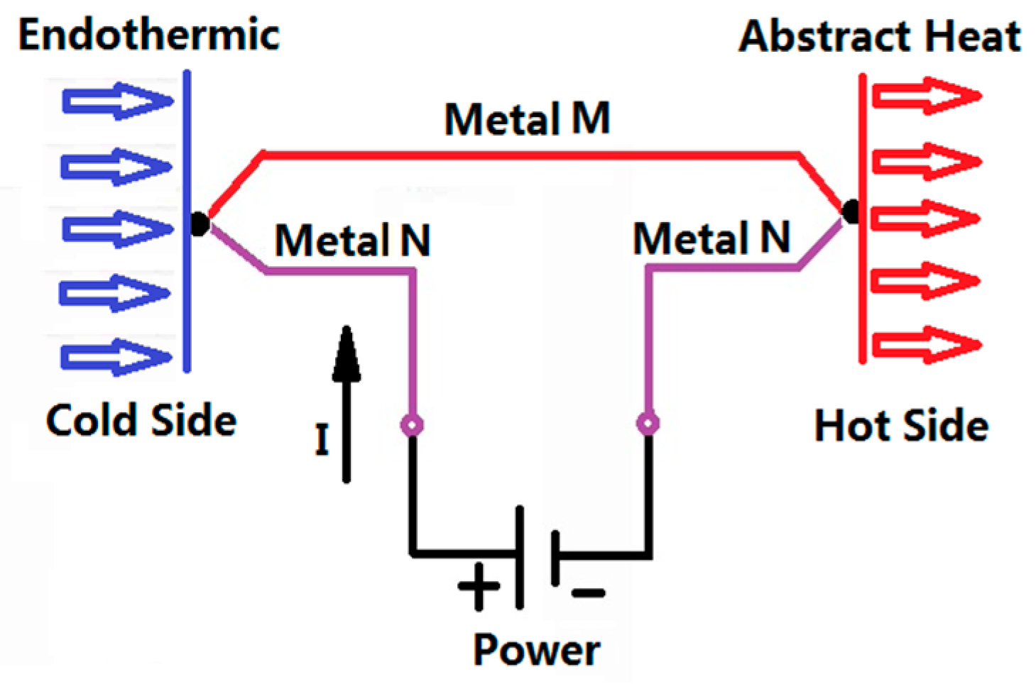
The second thermoelectric effect is known as the Peltier effect [21]. When there is a current through the circuit composed of different conductors, in addition to producing irreversible Joule heat, the different conductors at the junction with the direction of the current will have different heat absorption, which is an exothermic phenomenon. Assuming that the number of free electrons in the A terminal is large, the number of free electrons at the B end is small, and if the current flows from A to B, the temperature at the B end will increase; conversely, the temperature of the B side will be reduced. The schematic diagram is shown in Figure 1. As early as 1834, Peltier found this phenomenon, but because the technical conditions were not allowed at that time, it was not popularized. Now, with the rapid development of semiconductor technology, thermoelectric chips and thermoelectric coolers were produced [22]. A semiconductor thermoelectric chip is made up of several hundred pairs of thermocouples, and the temperature control can be realized at both ends of the cold and heat. Manoj et al. [23] designed a vehicle refrigeration and air conditioning system using thermoelectric chips as the core cooling measures, and designed the corresponding heat sink device. Through comparison, the effect of this air conditioning system is better than the traditional air conditioning system. Kaushik et al. [24] gave the number of thermocouples in the first and second stages of a Thermoelectric Chip (TEC) for maximum cooling power energy, and the exergy efficiency conditions were optimized. Meng et al. [25] showed the effects of a thermocouple’s physical size on the performance of a thermoelectric heat pump (TEH) driven by a thermoelectric generator (TEG). The schematic diagram of heat transfer for a thermoelectric chip is shown in Figure 2 [26].
A thermoelectric chip has the characteristic of absorbing heat at one end and releasing heat at the other end, and is also called a heat pump. Then, assuming that the temperature of the heat node is Th, the heat released to the environment is Qh. The cold junction temperature is Tc, and the heat absorbed from the outside (refrigerating capacity) is Q0. The input power of the thermocouple is W, and the current in the loop is I. If all possible losses are not considered, Equation (1) can be obtained from the first law of thermodynamics.
Perle absorption heat:
where π is the coefficient of peltier, which is determined by the beta coefficient (α) and the cold end temperature (Tc).
Joule heat:
where R is the resistance of the thermoelectric element. If the couple arm length is L, ρ1 and ρ2 are the resistivity, and the cross section areas are S1 and S2, then:
Due to the heat conduction of a semiconductor, a certain amount of heat is passed from the hot end to the cold end.
where k represents the total thermal conductivity of a thermoelectric element with a length equal to L.
where the coefficient of thermal conductivity of the two electric couple arms is and , respectively. Finally, we determine the heat absorbed by the cold end from the outside world.
Quantity of heat production:
To make the thermoelectric thermostat module work properly, the applied voltage needs to be equal to the pressure drop plus the Seeback voltage. The corresponding input power is P.
Refrigeration coefficient of thermoelectric refrigeration:
Merit coefficient:
where is the electrical conductivity of the thermoelectric components.
The maximum refrigerating capacity of the thermoelectric refrigeration module under certain conditions and the acquisition of the coefficient of refrigeration depend on the merit coefficient of the material. There is a positive correlation between the coefficient of merit and the effect of refrigeration. As long as the heat in the hot end can be taken out in time, the heat transfer efficiency of the thermoelectric chip will be greatly improved.
In this study, TEC-12708 thermoelectric chips (current 8 A, voltage 15.2 V, maximum cooling efficiency 76 W, produced by KJLP (SHENZHEN) ELECTCONICS Co., Ltd., Shenzhen, China) were used. The corresponding parameters are shown in Table 1.
In order to regulate the temperature of the battery, a combined liquid and thermoelectric cooling system was adopted, especially for when the battery temperature is too high. The thermoelectric chips and water cooling system were arranged on the surface of the battery in the proper order, and the heat was transported from the battery to the water cooling system by the thermoelectric cooler chips. Therefore, the adjustment of the battery’s temperature may be achieved.
3. Model Analysis and Structure Optimization
3.1. Three-Dimensional (3D) Model Design and Grid Partition
The L148F20 LiFePO4 battery was selected in the present work, which has a rated voltage of 3.2 V and a capacity of 20 AH. The physical geometries parameters of the battery and heat exchanger are shown in Table 2. As shown in Figure 3, based on the related geometries parameters, a single cell model, a water cooling model, and a thermoelectric cooling model were established in Solidworks 16.0 (Dassault Systemes S.A, Vélizy-Villacoublay, France).
Then, hexa-dormant structured mesh was drowned by ICEMCFD (ANSYS, Inc., Canonsburg, PA, USA) Hexa-dormant structured mesh has better orthogonality, a higher calculation accuracy, and a fast computation speed. Because the complexity of the geometric model will increase the computation resources required and the complicated geometry model may easily create an error in the simulation, in this paper the model was simplified to a heat source that was heated with the rate of 100 W from the inside. The mesh model is shown in Figure 4. The number of cells, faces, and nodes of the single battery is 230,131, 703,861, and 243,824, respectively. The number of cells, faces, and nodes of the water cooling model is 129,021, 399,860, and 141,792, respectively. The number of cells, faces, and nodes of the simplified thermoelectric model is 293,242, 843,808, and 266,435, respectively.
The model was simulated using Fluent in the ANSYS 17.0. The details of the parameters are shown in Table 3; all other parameters used the system default.
3.2. Heat Generation Model of Battery
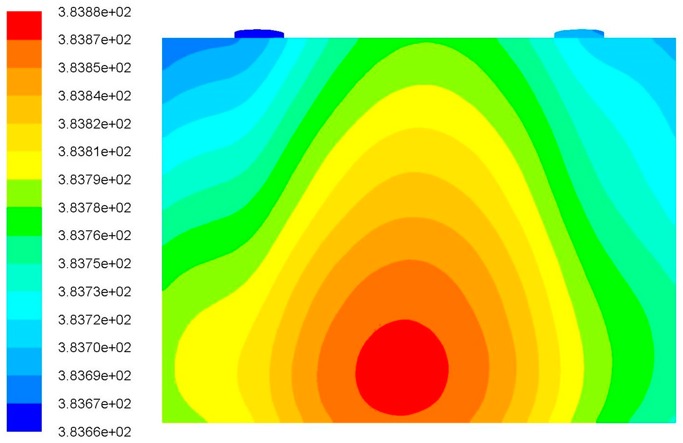
In the introduction of this paper, it is pointed out that many scholars have simplified the battery to be an internal homogeneous heating body. This article also follows this method. Then, a battery model was built with a heating rate of 100 W and an ambient temperature of 298.15 K using ANSYS 17.0. The temperature profiles of the battery under natural convection are shown in Figure 5. The maximum temperature of the battery is 383.8 K, and the battery’s center position is slightly hotter compared to the battery’s edge. This is in line with the mechanism of the heat production of the battery. Then, the above model was regarded as a reference and the following work was based on this model. To keep the simulation comparable, the battery parameters are consistent with the heating power of the battery in the temperature regulation. The temperature regulation is determined and improved by comparing the surface temperature of water cooling with that of thermoelectric cooling, and the optimal temperature profile of the battery was obtained.
3.3. Structure Design and Optimization of Heat Exchanger
According to the temperature profiles of the battery, it can be seen that the simplified model of the thermoelectric chip should be placed in the central position of the positive surface of the battery. Based on the heating mechanism of the battery and the structure of the thermoelectric chip, two structures of a heat exchanger for the cooling system were designed. The diameter of the inlet and the outlet is 18 mm. As shown in Figure 6, the lower left is the inlet of the coolant and the upper right is the outlet. The other picture is the structure B, in which the left lower mouth is the inlet of the coolant and the upper left is the outlet.
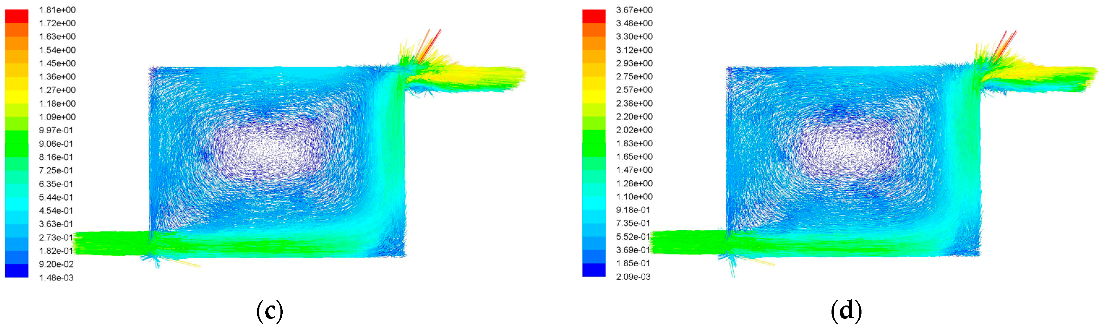
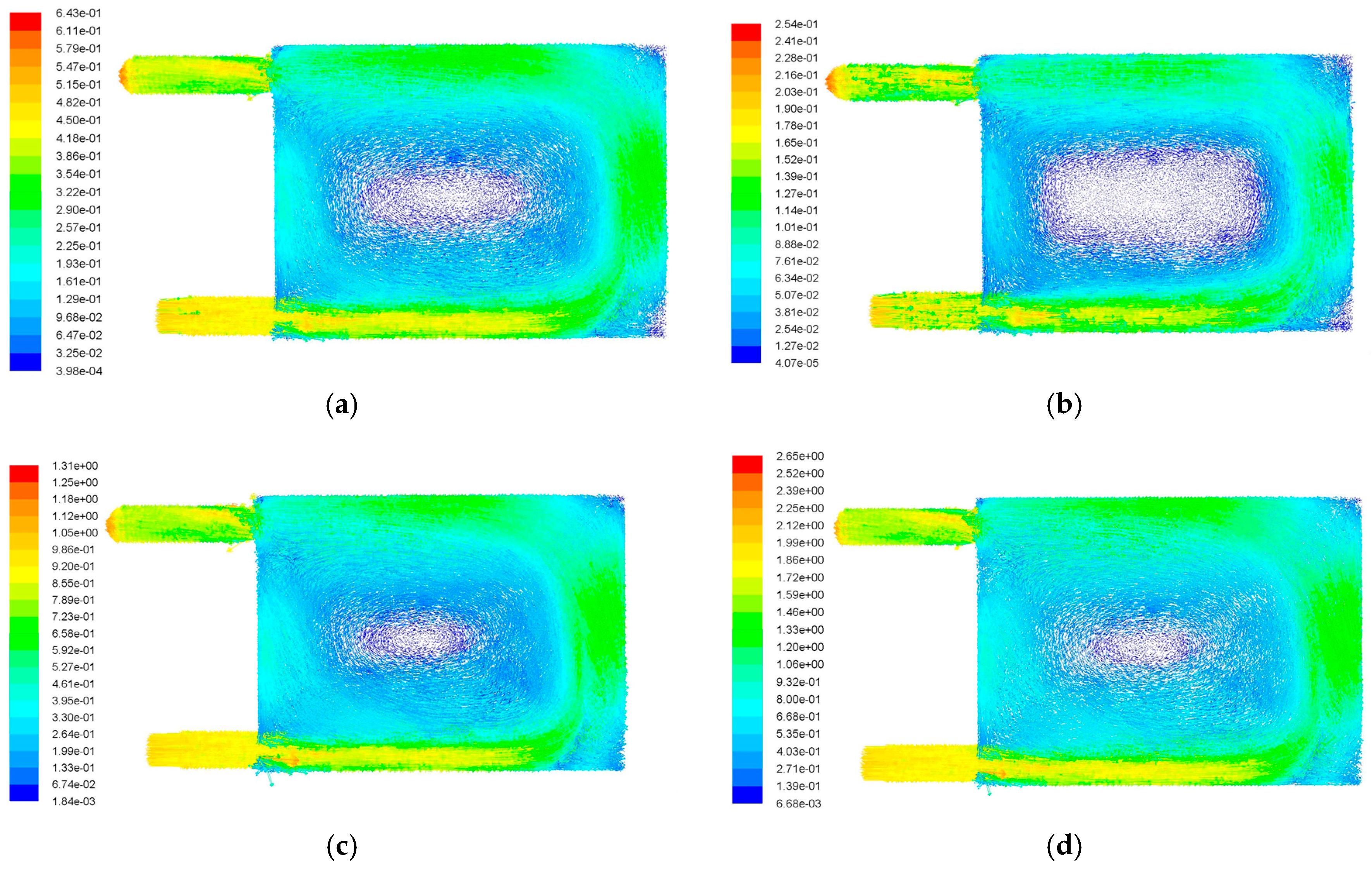
Four different inlet velocities, v = 0.2 m/s, v = 0.5 m/s, v = 1.0 m/s, and v = 2.0 m/s, were adopted in the simulation of structure A, and the corresponding velocity vectors were obtained as shown in Figure 7. The flow velocity distribution is Z-shaped, and the velocity is slow or even close to zero at the center of the channel. This phenomenon decreased with the increase of flow rate, but did not disappear. Similarly, four different inlet velocities, v = 0.2 m/s, v = 0.5 m/s, v = 1.0 m/s, and v = 2.0 m/s, were adopted for structure B, and the corresponding velocity vectors were obtained as shown in Figure 8. The results show that the distribution of the liquid velocity is relatively uniform. However, the velocity of the central position of the flow channel is still relatively slow when the flow rate is 0.2 m/s, and even close to zero at some locations. It was found that increasing the flow velocity of the inlet coolant could alleviate this phenomenon. The vortex phenomenon at the central part of the flow channel is further weakened when the flow velocity increases to 1.0 m/s, and the flow velocity is basically uniform within the whole flow channel. However, the phenomenon reappeared again when the flow velocity further increased. It is concluded that the stagnation of the liquid at the channel center firstly decreased and then increased with the increase of the flow velocity. Therefore, it is maybe the better choice to have a flow velocity of 1.0 m/s.
Generally, the cooling effects of the above two structures are different under the same conditions, as shown in Figure 7 and Figure 8. The fluid velocity in the flow channel is more uniform for the scheme B, which is a relatively better solution. Moreover, the flow velocity of v = 1.0 m/s is a better choice.
3.4. Cooling Effect of the Modified Cooling Structure
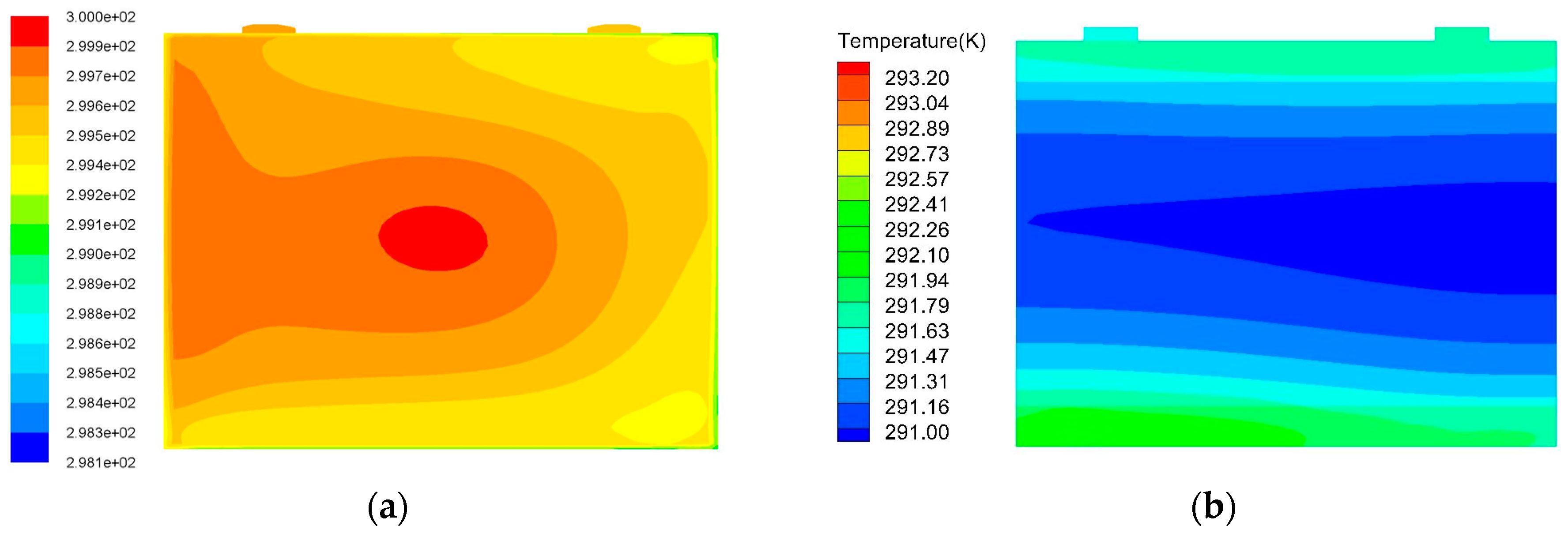
Based on the previous mesh grid model, the cooling effects of the modified cooling structure were analyzed. At the same time, they were compared with the effect of liquid cooling. The inlet flow velocity of the heat exchanger is 1.0 m/s, and the inlet temperature of the liquid coolant is 298.15 K. The corresponding surface temperature distributions are shown in Figure 9.
It can be seen that the temperature distribution of the combined thermoelectric cooling system is more uniform and the maximum temperature of the battery could be reduced to 291 K. In fact, if the power of the thermoelectric chip is further improved and the heat of heat end can be exported in time, the cooling effect will be better. Thus, the combination system of liquid and thermoelectric cooling is applied in the present paper.
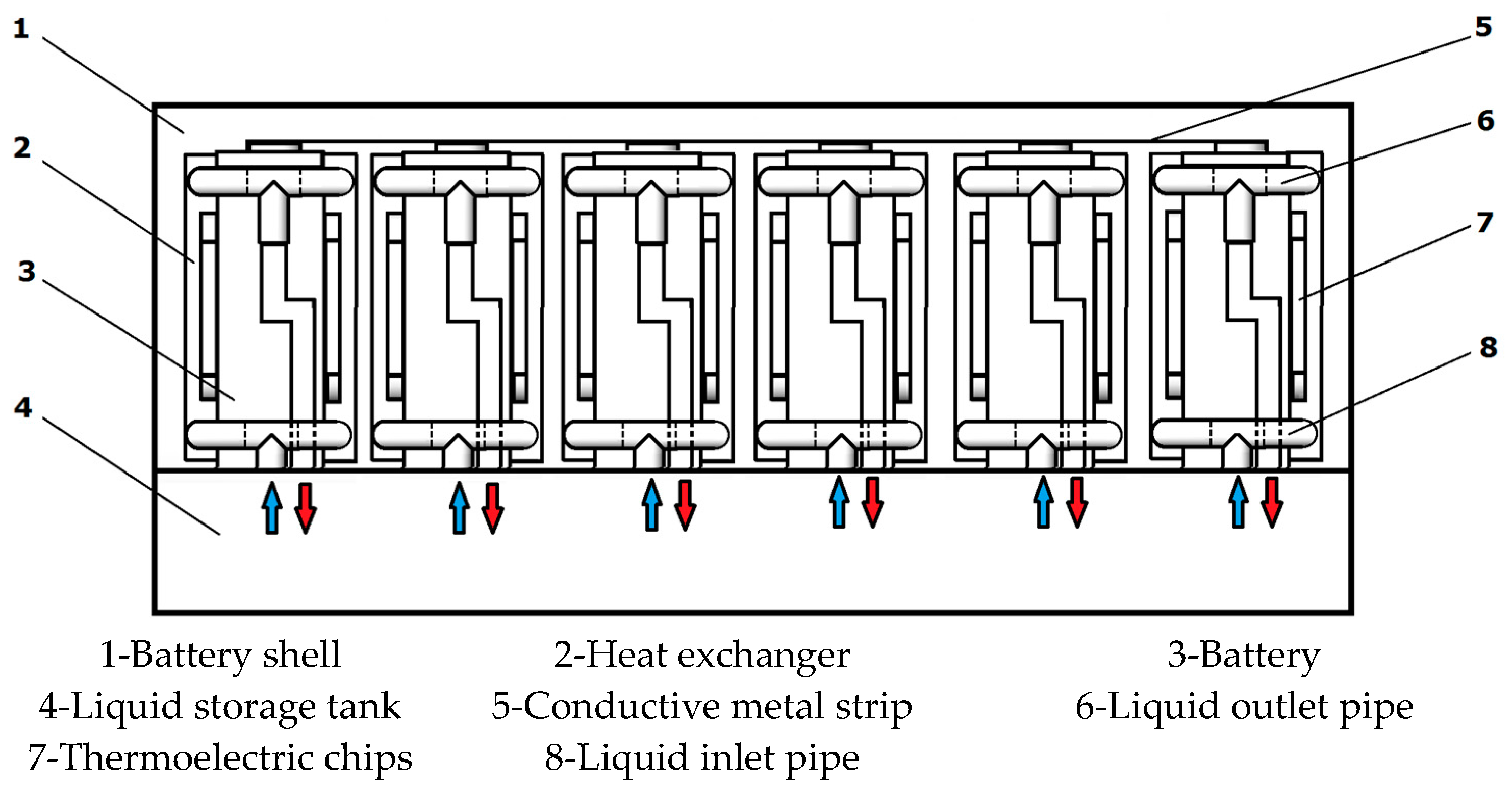
3.5. Pack Model Design
According to the best structure determined above, we designed the pack model of the battery group. The corresponding thermostat structure and thermoelectric chip are added at the same time, the schematic of which is shown in Figure 10. The bottom of the heat exchanger is connected with the liquid inlet of the temperature regulating pipeline, and the top is connected with the liquid outlet of the temperature regulating pipeline. The heat exchanger has a thermoelectric card slot that can be plugged into six thermoelectric chips, which is equivalent to twelve thermoelectric chips for each battery. The symmetrical structure design can ensure full contact between the battery and the temperature control module, which is helpful to improve the temperature control efficiency.
4. Control System Design
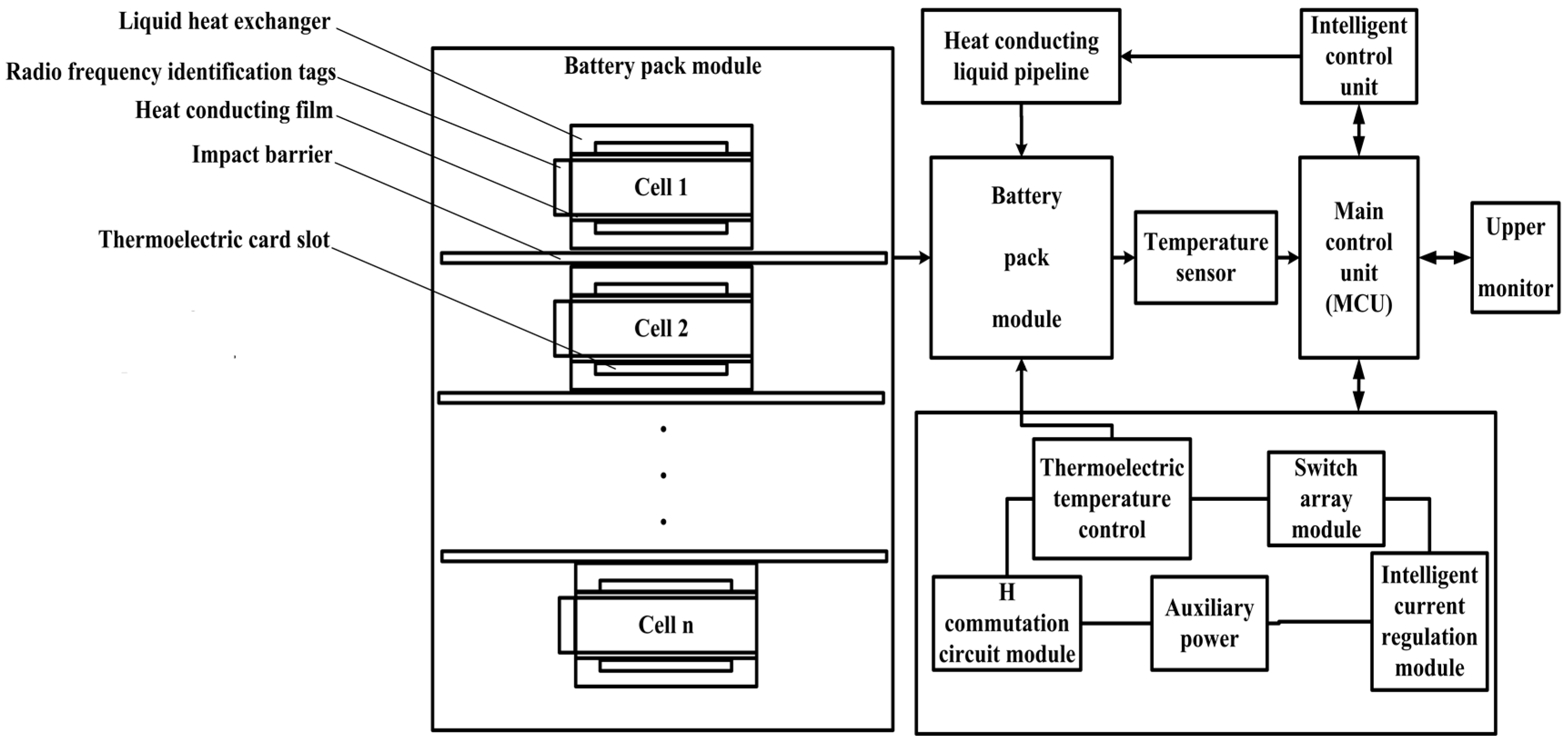
According to the above analysis, the corresponding thermal control system was designed and the schematic of the control procedure is shown in Figure 11. The battery thermal management system includes two parts: the battery pack and the control unit. The combination temperature control system of thermoelectric and liquid cooling is adopted. The specific implementation process is listed as follows:
- The temperature sensor collects the temperature of each cell and feeds it back to the MCU (main control chip);
- The main control chip is used to determine whether there is a need to adjust the temperature according to the data in the comparison program. If necessary, break over the relative single cell battery switch array module and the H commutation circuit module;
- The flow rate on the thermoelectric chip is controlled through the intelligent module of flow control so as to control the temperature of the cold end and the hot end of thermoelectric chip, to achieve the purpose of regulating the surface temperature of the battery.
The H commutation circuit is used to control the forward current when the temperature of the battery is too high, and it can control the reverse flow of the current when the battery temperature is too low. The intelligent hydraulic control unit is controlled by the main controller, and the flow rate of the internal liquid is adjusted in order to regulate the temperature of the thermoelectric chip. In order to effectively control the temperature of the battery, the thermoelectric chip should be tightly in contact with the battery. Additionally, a concave structure was designed to ensure that the battery was in effective contact with the flow channel and also as an auxiliary regulating module to adjust the temperature of the battery.
4.1. Hardware Design
In this study, TMS320LF2812 (a 32 bit chip produced by Texas Instruments Company, Dallas, TX, USA) was used as the master chip and the corresponding peripheral circuit was designed. Among them, the key circuit module includes the temperature acquisition module, the H commutation circuit module, the matrix switch circuit module, and the wireless communication module.
4.1.1 Temperature Acquisition Circuit
The accurate collection of the battery temperature is the premise of the thermal management of the battery. The DS18B20, a digital temperature sensor (produced by Dallas Semiconductor, Dallas, TX, USA) was selected to realize the temperature acquisition. It has the advantages of accurate acquisition, a wide range, a wide application, and so on [27]. The circuit diagram is shown in Figure 12. The temperature information collected by DS18B20 will be passed to the main control chip through two I/O interfaces of TMS320F2812, PTD2 and PTD3.In order to fully use the characteristics of DS18B20, twelve units were used, which were divided into two groups. Each one is attached to the surface of an individual cell so as to accurately collect the temperature information of each battery.
4.1.2. H Commutation Circuit Module
In order to realize the switch between the hot end and the cold end of the thermoelectric sheet, the H commutation circuit module was designed to change the direction of the current flowing into the sheet. The circuit schematic is shown in Figure 13.
As shown in Figure 13, Q1 and Q3 are PNP triode; Q2 and Q4 are NPN triode. They are controlled by four GPIO driver ports of TMS320F2812. F1 and F2 are fuses to prevent the circuit from short circuit, and the middle of the block represents the thermoelectric sheets. The corresponding current direction is displayed in Table 4.
4.1.3. Matrix Switch Circuit Module
In order to realize the control of the thermoelectric power, a matrix switch circuit module was added to the drive circuit module. The positioning principle of the module is the ij positioning principle. i represents the number of the single battery and the value is 1–12; j represents the thermoelectric chip group and the value is 1–2. The corresponding switch symbol is represented by Kij.
4.1.4. Wireless Communication Module
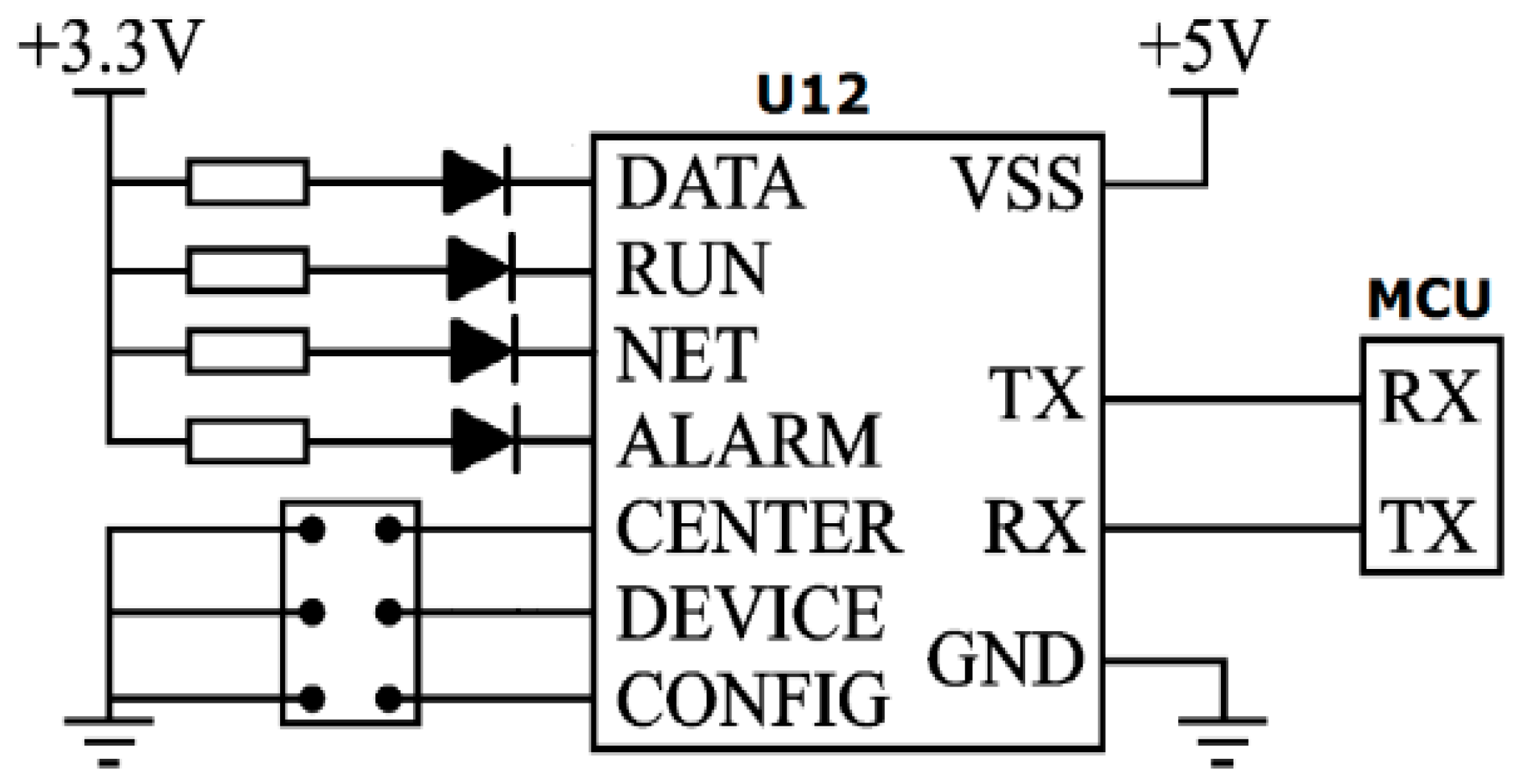
In order to realize the communication between the host controller and the host computer, the SZ05 wireless communication module was adopted based on the ZigBee protocol, which has the advantages of far communication distance, strong anti-interference ability, flexible networking, and reliable and stable performance. The interface circuit of the wireless communication module is shown in Figure 14. The RX and TX ports of the wireless communication module are connected with a TMS320F2812 serial connection; TX is the interface of sending data, and RX is a data receiving interface. The main control chip and the wireless communication module have RX and TX interface to realize the interaction of information.
4.2. Design of Software
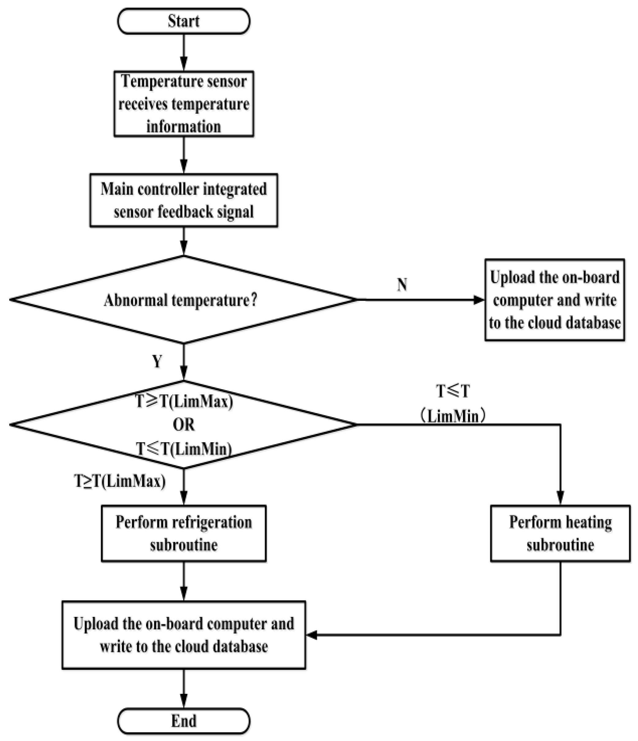
The software of battery thermal management system is mainly based on the C language, and the master control chip is carried out under the Code Composer Studio (CCS). CCS is an integrated development environment dedicated to the development of Digital Signal Processing (DSP) products produced by TI companies. The procedures for the implementation of the process are: system power, initialization, and detection of system failure. After initialization, the main program is running. The temperature information of the battery is collected to judge whether the temperature is in the appropriate range. If yes, the temperature information directly transfers to the host computer. If no, the program judges whether the temperature is too high or too low. The refrigeration subroutine is performed when it is too high; otherwise, the thermal subroutine is performed when it is too low. The flow chart of program is shown in Figure 15.
When the temperature of the battery that is detected by the main controller is too high, or even exceeds the safety limit TLimMax, the refrigeration control strategy is applied. The specific steps are as follows:
- (1)
- Capture the coordinates of the battery and display them on the battery simulator according to the temperature level;
- (2)
- The battery voltage Uij0, current I, and the estimated value of SOC are collected by the battery management system. The heating rate is determined to match the cloud database by the feedback information of the electronic label;
- (3)
- According to the corresponding relationship between the SOC and the open circuit voltage, the open circuit voltage of the battery is predicted;
- (4)
- The heating efficiency of battery’s surface is calculated according to the collected battery information from the following formula:where I is the charge and discharge current of the battery, VB is the volume of the battery, UOpen is the open circuit voltage of the battery, ΔU is the difference between the open circuit voltage and the terminal voltage of the battery, Tij0 is the surface temperature of the battery, and is the temperature coefficient.
- (5)
- The required cooling efficiency is determined according to the heating rate of the battery. Using the fuzzy control strategy, the cold end heat absorption rate Qm is equal to KTij0 multiplied by QB. Then, wait until the temperature sensor detects the battery surface temperature in the best operating temperature range (Tm, Tn), and make QB equal to Qm. At the same time, the hot end of the thermoelectric chip is contacted with the heat transfer structure so as to use the flow of the heat transfer structure’s internal liquid to take away the excess heat. The flow rate of the cooling system is regulated by adjusting the regulating valve of the liquid heating/cooling structure so as to adjust the auxiliary cooling efficiency.
- (6)
- Check the temperature of the battery again. The cooling circuit of the battery is cut off when the temperature is OK, and then the data are recorded and uploaded to the on-board computer and cloud database.
Similarly, when the temperature of the battery that is detected by the main controller is too low or lower than the safety limit TLimMin, the heating control strategy will be applied. The difference is that the direction of the cold and hot direction is changed through the H reversing circuit for the thermoelectric chips. At the same time, the interior of the auxiliary heat transfer structure will be filled with a higher temperature liquid.
5. Conclusions
In this paper, an enhanced battery thermal management system, based on the second thermoelectric effect, is proposed. The main contributions of this study are to introduce the structural design optimization and control method. Among them, the most special part is the use of thermoelectric chips, which increase the temperature regulation efficiency of the battery’s thermal management system in theory. By a finite element analysis of the flow field, the best liquid cooling structure and the inlet velocity are determined. The result shows that the enhanced cooling structure is more effective in cooling than the traditional one. In the meanwhile, the relative battery pack structure and the temperature control system are developed accordingly. The conclusions are drawn as follows:
- (1)
- A thermoelectric chip integrated into the liquid cooling unit is a better design for a battery’s thermal management system.
- (2)
- In the process of improving the heat exchanger structure, it is noted that the flow field distribution of the U-shape is more uniform than that of the Z-shape.
- (3)
- The vortex phenomenon at the center of the U-shape heat exchanger is initially weakened and then intensified as the inlet velocity of the pipe is increased. When the inlet velocity is 1 m/s, the distribution of the flow field is the most uniform.
- (4)
- The design process of this enhanced battery thermal management system can provide a wealth of guidelines for solving similar problems.
Acknowledgments
This work was supported by the Natural Science Foundation of Shaanxi Province of China (2016GY-007). Meanwhile, it was financially supported by the Xi’an University of Science and Technology.
Author Contributions
Chuan-Wei Zhang conceived and designed the whole structure of the system and determined the optimal cooling structure model. Ke-Jun Xu analyzed the temperature modulation effect of the traditional structure and the improved structure. Lin-Yang Li and Man-Zhi Yang designed the hardware and software of the control system. Chuan-Wei Zhang and Ke-Jun Xu wrote the paper. Huai-Bin Gao and Shang-Rui Chen gave a general guide for the study and improved the language level of this paper.
Conflicts of Interest
The authors declare no conflict of interest.
References
- Li, J.H.; Barillas, J.K.; Guenther, C.; Danzer, M.A. Multicell state estimation using variation based sequential Monte Carlo filter for automotive battery packs. J. Power Sources 2015, 277, 95–103. [Google Scholar] [CrossRef]
- Rosario, M.; Fabio, V. Designing a Sustainable University Recharge Area for Electric Vehicles: Technical and Economic Analysis. Energies 2017, 10, 1604. [Google Scholar]
- Lu, L.G.; Li, J.Q.; Hua, J.F.; Ouyang, M.G. Key technology of electric vehicle lithium ion battery management system. Chin. J. Sci. Technol. Rev. 2016, 6, 39–48. [Google Scholar]
- Gao, Z.H.; Chin, C.S.; Chiew, J.H.K.; Jia, J.; Zhang, C.Z. Design and Implementation of Smart Lithium-ion Battery System with Real-time Fault Diagnosis Capability for Electric Vehicles. Energies 2017, 10, 1503. [Google Scholar] [CrossRef]
- Wu, X.G.; Lv, S.Y.; Chen, J.Z. Determination of the optimum heat transfer coefficient and temperature rise analysis for a Lithium-ion battery under the conditions of Harbin city bus driving cycles. Energies 2017, 10, 1723. [Google Scholar] [CrossRef]
- Amine, K.; Liu, J.; Belharouak, I. High-temperature storage and cycling of C-LiFePO4 graphite Li·ion cells. J. Electrochem. Commun. 2005, 7, 669–673. [Google Scholar] [CrossRef]
- Li, Z.; Han, X.B.; Lu, L.G.; Ouyang, M.G. Temperature characteristics of power LiFePO4 batteries. J. Mech. Eng. 2011, 18, 115–120. [Google Scholar] [CrossRef]
- Smith, K.; Wang, C.Y. Power and thermal characterization of a Li-ion battery pack for hybrid electric vehicles. J. Power Sources 2006, 160, 662–673. [Google Scholar] [CrossRef]
- Gao, Z.C.; Chin, C.S.; Woo, W.L.; Jia, J.B. Integrated Equivalent Circuit and Thermal Model for Simulation of Temperature-Dependent LiFePO4 Battery in Actual Embedded Application. Energies 2017, 10, 85. [Google Scholar] [CrossRef]
- Chiew, J.; Chin, C.S.; Jia, J.B.; Toh, W.D. Thermal Analysis of a Latent Heat Storage based Battery Thermal Cooling Wrap. In Proceedings of the COMSOL Conference 2017, Singapore, 22 November 2017. [Google Scholar]
- Li, B.; Chang, G.F.; Lin, C.J.; Xu, S.C. Research on heat generate mechanism of Li-ion batteries for electric vehicles. Chin. J. Power Sources 2017, 2, 378–381. [Google Scholar]
- Chen, K.; Li, Z.Y.; Chen, Y.M.; Long, S.M.; Hou, J.S.; Song, M.X.; Wang, S.F. Design of parallel air-cooled battery thermal management system through numerical study. Energies 2017, 10, 1677. [Google Scholar] [CrossRef]
- Chen, K.; Wang, S.F.; Song, M.X. Structure optimization of parallel air-cooled battery thermal management system. Int. J. Heat Mass Transf. 2017, 4, 943–952. [Google Scholar] [CrossRef]
- Yu, K.; Yang, Y.; Li, C.C. Thermal analysis and two-directional air flow thermal management for lithium-ion battery pack. J. Power Sources 2014, 270, 193–200. [Google Scholar] [CrossRef]
- Saw, L.H.; Ye, Y.; Tay, A.A.O.; Chong, W.T.; Kuan, S.H.; Yew, M.C. Computational fluid dynamic and thermal analysis of Lithium-ion battery pack with air cooling. Appl. Energy 2016, 177, 783–792. [Google Scholar] [CrossRef]
- Yuan, H.; Wang, L.F.; Wang, L.Y. Battery thermal management system with liquid cooling and heating in electric vehicles. J. Automot. Saf. Energy 2012, 4, 371–380. [Google Scholar]
- Huo, Y.T.; Rao, Z.H.; Liu, X.J.; Zhao, J.P. Research development of battery thermal management system based on liquid medium. Adv. New Renew. Energy 2014, 2, 135–140. [Google Scholar]
- Lin, C.J.; Xu, S.C.; Chang, G.F. Thermal uniformity and enhanced thermal transfer of rectangular Lithium-ion power batteries. J. Automot. Technol. 2014, 10, 55–58. [Google Scholar]
- Ramandi, M.Y.; Dincer, I.; Naterer, G.F. Heat transfer and thermal management of electric vehicle batteries with phase change materials. Heat Mass Transf. 2011, 7, 777–788. [Google Scholar] [CrossRef]
- Wei, Z.H.; Xu, S.C.; Li, Z.; Lin, C.J. Study on thermal management package LiFePO4 battery based on phase change material and liquid cooling. Chin. J. Power Sources 2016, 1, 44–46. [Google Scholar]
- Ma, X.F.; Zhou, D.Q.; Liu, X.S.; Li, L.Y. Research progress of phase change materials for thermal management of power batteries. New Chem. Mater. 2017, 9, 23–25. [Google Scholar]
- Florin, S.; Venetia, S.; Stefan, N.; Adrian, I.D. Data acquisition and virtual instrumentation system for the study of Peltier and Seebeck effects. In Proceedings of the International Conference on Optimization of Electrical and Electronic Equipment, Brasov, Romania, 20–22 May 2016. [Google Scholar]
- Manoj, S.R. Thermoelectric air cooling for cars. Int. J. Eng. Sci. Technol. 2012, 5, 2381–2394. [Google Scholar]
- Kaushik, S.; Manikandan, S. The influence of Thomson effect in the performance optimization of a two stage thermoelectric cooler. Cryogenics 2015, 72, 57–64. [Google Scholar] [CrossRef]
- Meng, F.; Chen, L.; Sun, F. Effects of thermocouples’ physical size on the performance of the TEG–TEH system. Int. J. Low-Carbon Technol. 2016, 3, 375–382. [Google Scholar] [CrossRef]
- Meghali, G.; Dhanashri, S.; Abhijit, K.; Bhandwalkar, S. Review on thermoelectric refrigeration: Materials and technology. Int. J. Curr. Eng. Technol. 2017, 4, 67–71. [Google Scholar]
- Liu, Z.J. Multi point temperature measurement system based on DS18B20. Adv. Mater. Res. 2013, 9, 756–759. [Google Scholar] [CrossRef]
Figure 1.
Peltier effect.

Figure 2.
Heat transfer of a thermoelectric chip.
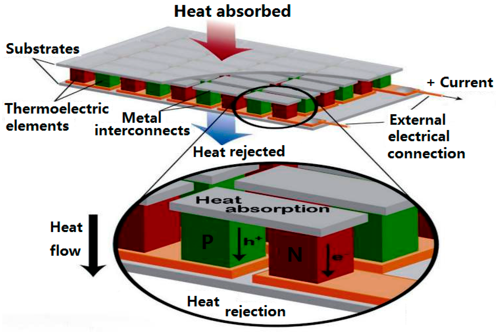
Figure 3.
Three-dimensional model. (a) Single battery model; (b) Water cooling model; (c) Thermoelectric cooling model.
Figure 3.
Three-dimensional model. (a) Single battery model; (b) Water cooling model; (c) Thermoelectric cooling model.
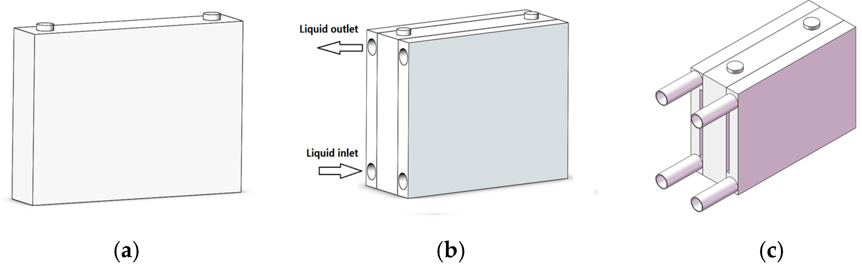
Figure 4.
Mesh model. (a) Single battery model; (b) Water cooling model; (c) Thermoelectric cooling model.
Figure 4.
Mesh model. (a) Single battery model; (b) Water cooling model; (c) Thermoelectric cooling model.
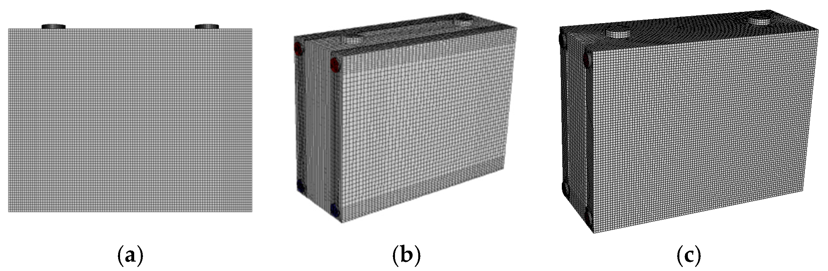
Figure 5.
Temperature profiles of the battery under natural convection.

Figure 6.
Structures of liquid cooling method. (a) Structure A; (b) Structure B.
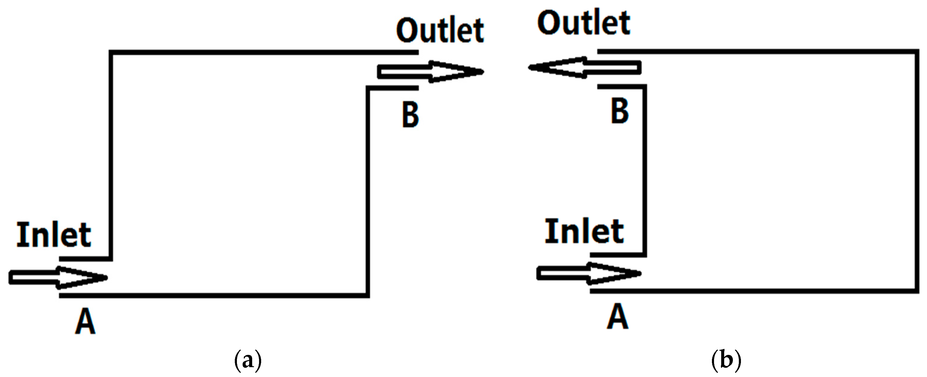
Figure 7.
Velocity vectors of structure A. (a) v = 0.2 m/s; (b) v = 0.5 m/s; (c) v = 1 m/s; (d) v = 2 m/s.
Figure 7.
Velocity vectors of structure A. (a) v = 0.2 m/s; (b) v = 0.5 m/s; (c) v = 1 m/s; (d) v = 2 m/s.
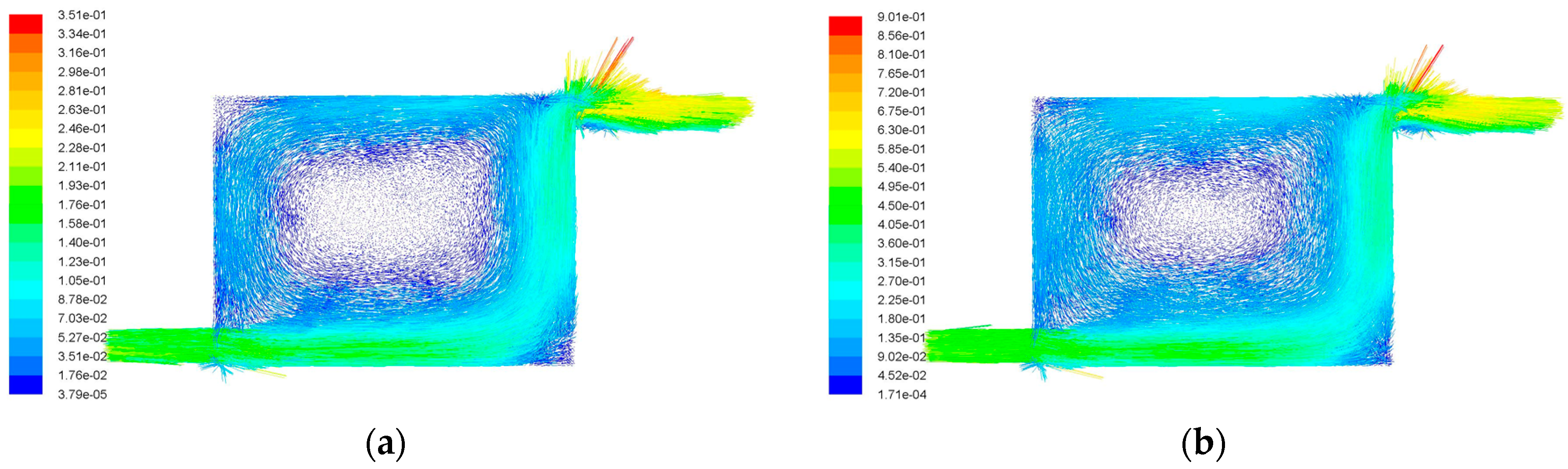

Figure 8.
Velocity vectors of structure B. (a) v = 0.2 m/s; (b) v = 0.5 m/s; (c) v = 1.0 m/s; (d) v = 2.0 m/s.
Figure 8.
Velocity vectors of structure B. (a) v = 0.2 m/s; (b) v = 0.5 m/s; (c) v = 1.0 m/s; (d) v = 2.0 m/s.

Figure 9.
Temperature profiles of liquid cooling and combined with thermoelectric cooling. (a) Liquid cooling; (b) combined liquid and thermoelectric cooling.
Figure 9.
Temperature profiles of liquid cooling and combined with thermoelectric cooling. (a) Liquid cooling; (b) combined liquid and thermoelectric cooling.

Figure 10.
Battery pack model.

Figure 11.
Schematic of the control procedure.

Figure 12.
Temperature sampling circuit.
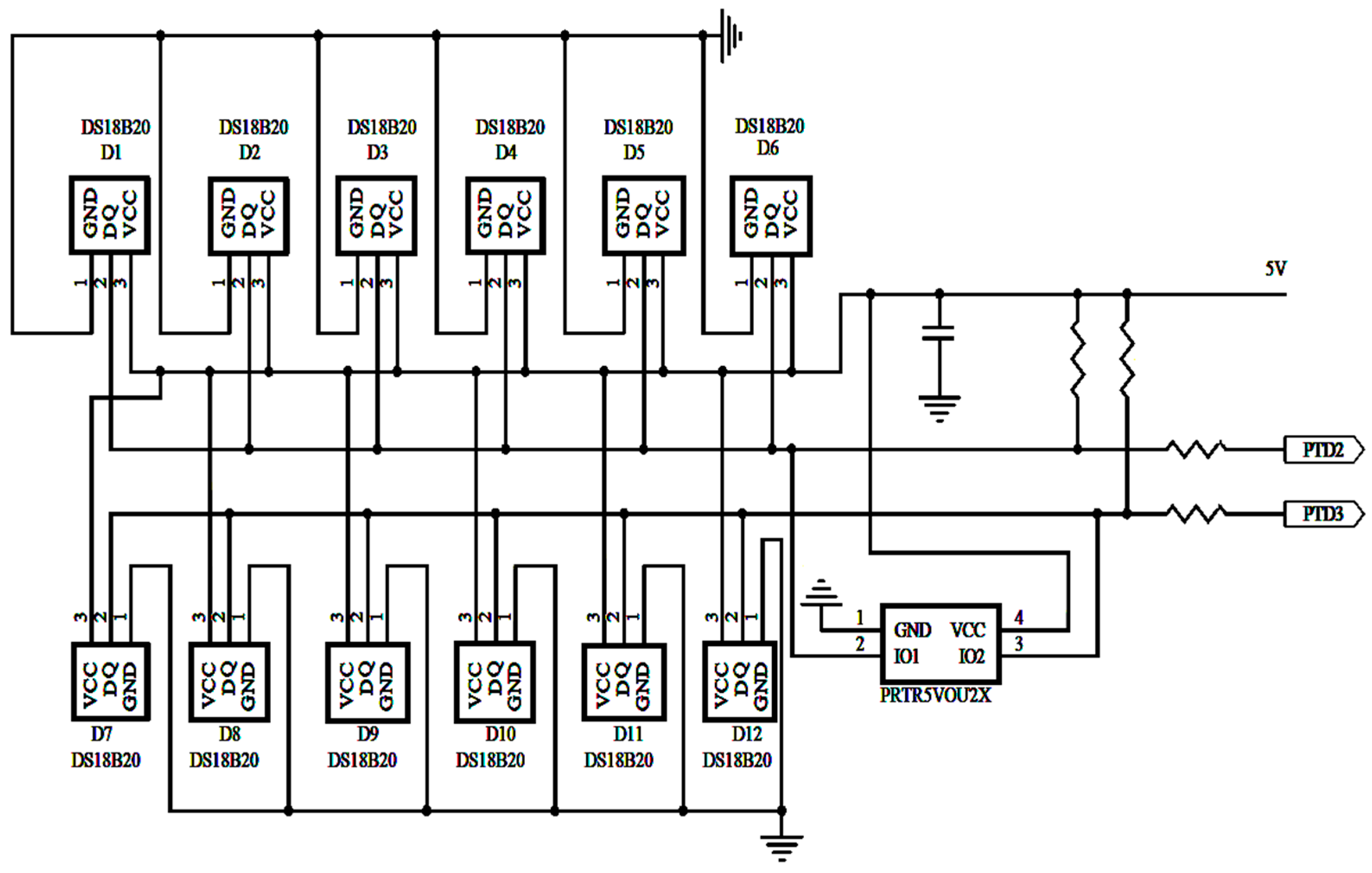
Figure 13.
H commutation circuit.
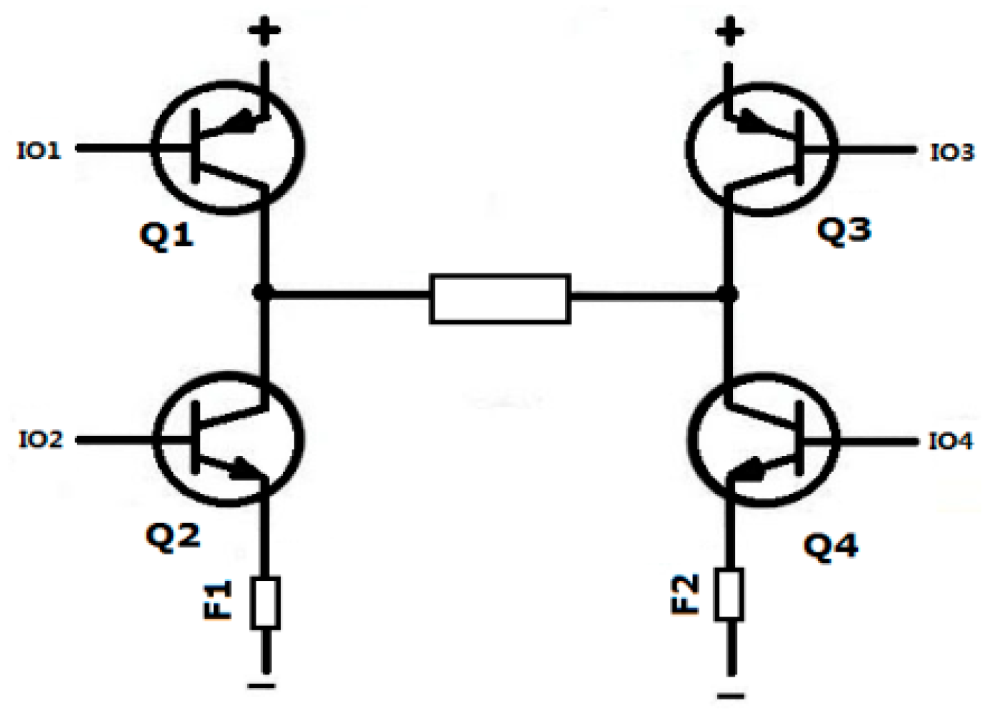
Figure 14.
Wireless communication modules.

Figure 15.
Main schematic of temperature regulation.

Table 1.
Parameters of the thermoelectric chip.
| Characteristic | Parameter | Characteristic | Parameter |
|---|---|---|---|
| Type | TEC-12708 | Size | 40 mm × 40 mm × 3.2 mm |
| Voltage | 12 V | Maximum current | 8 A |
| Maximum temperature difference | 70 K | maximum refrigeration power | 76 W |
Table 2.
Physical geometries parameters.
| Length (mm) | Width (mm) | Height (mm) | |
|---|---|---|---|
| Single battery | 200 | 40 | 150 |
| Heat exchanger | 200 | 20 | 150 |
| Simplified Thermoelectric | 200 | 6 | 106 |
Table 3.
Simulation parameter details.
| Item | Features | Item | Features |
|---|---|---|---|
| Viscous | k-epsilon | Solid | Aluminum |
| Fluid | Water-liquid | Heating rate | 100 W |
| Velocity-inlet | 1 m/s | Solution method | Pressure–velocity coupling/SIMPLE |
| Temperature | 298.15 K | Criteria for convergence | Energy/1e-06 |
Table 4.
Current direction.
| IO1 | IO2 | IO3 | IO4 | Result |
|---|---|---|---|---|
| 1 | 0 | 0 | 1 | Forward current |
| 0 | 1 | 1 | 0 | Reverse current |
© 2018 by the authors. Licensee MDPI, Basel, Switzerland. This article is an open access article distributed under the terms and conditions of the Creative Commons Attribution (CC BY) license (http://creativecommons.org/licenses/by/4.0/).
Share and Cite
MDPI and ACS Style
Zhang, C.-W.; Xu, K.-J.; Li, L.-Y.; Yang, M.-Z.; Gao, H.-B.; Chen, S.-R. Study on a Battery Thermal Management System Based on a Thermoelectric Effect. Energies 2018, 11, 279. https://doi.org/10.3390/en11020279
AMA Style
Zhang C-W, Xu K-J, Li L-Y, Yang M-Z, Gao H-B, Chen S-R. Study on a Battery Thermal Management System Based on a Thermoelectric Effect. Energies. 2018; 11(2):279. https://doi.org/10.3390/en11020279
Chicago/Turabian StyleZhang, Chuan-Wei, Ke-Jun Xu, Lin-Yang Li, Man-Zhi Yang, Huai-Bin Gao, and Shang-Rui Chen. 2018. "Study on a Battery Thermal Management System Based on a Thermoelectric Effect" Energies 11, no. 2: 279. https://doi.org/10.3390/en11020279
Note that from the first issue of 2016, this journal uses article numbers instead of page numbers. See further details here.