Article

Design, Evaluation and Implementation of an Islanding Detection Method for a Micro-grid

1
College of Electrical Engineering, Zhejiang University, Hangzhou 310027, China
2
Department of Energy IT, Gachon University, Seoul 13120, Korea
3
Department of Electrical and Electronic Engineering, University of Manchester, Manchester M13 9PL, UK
*
Author to whom correspondence should be addressed.
Energies 2018, 11(2), 323; https://doi.org/10.3390/en11020323
Submission received: 30 December 2017 / Revised: 22 January 2018 / Accepted: 30 January 2018 / Published: 2 February 2018
(This article belongs to the Section F: Electrical Engineering)

Abstract

:
Correct and fast detection of a micro-grid (MG) islanding is essential to the MG since operation, control, and protection of the MG depend on its operating mode i.e., an interconnected mode or islanding mode. This study describes the design, evaluation and implementation of an islanding detection method for an MG, which includes a natural gas-fired generator, a doubly fed induction generator type wind generator, a photovoltaic generator, and some associated local loads. The proposed method is based on the instantaneous active and reactive powers at the point of common coupling (PCC) of the MG. During the islanding mode, the instantaneous active and reactive powers at the PCC are constants, which depend on the voltage of the PCC and the impedance of the dedicated line. The performance of the proposed method is verified under various scenarios including islanding conditions for the different outputs of the MG, and fault conditions by varying the position, type, inception angle and resistance of the fault, using the PSCAD/EMTDC simulator. This paper also concludes by implementing proposed method into a TMS320C6701 digital signal processor. The results indicate that the proposed method successfully detects islanding for the MG in islanding conditions, and remains stable in fault conditions.

1. Introduction

Distributed generations (DGs) are small-scale power generations, which are considered to be a promising approach as a solution of economic and environmental issues for conventional power systems [1,2,3]. DGs provide economic advantages to reduce the amount of energy lost in transmitting electricity, and the number and size of power distribution lines, since the electricity can be generated near where it is consumed. In addition, the integration of distributed renewable energy sources i.e., wind energy, solar energy, bio-energy, hydraulic energy and so on, into the traditional electric power system, can reduce the emission of the greenhouse gases, and thus solve the environmental problems. However, the limitation of integrating DGs is that, they must be obedient to the operating conditions of the interconnected distribution networks. When the grid breaks the connection between the distribution network and DGs, DGs must detect the islanding condition and immediately stop producing power, which is called anti-islanding. Otherwise, grid operators may not realize that a circuit is still powered by DGs, and automatic re-connection of devices may be prevented. This will reduce the capacity factor of DGs and increase the power lost in transmitting electricity, since the loads which were powered by DGs would be powered by other remote power sources.
To overcome this drawback, a better way to realize the emerging potential of the DG is to take a system approach which views the generation and the local loads as a subsystem, which is called a micro-grid (MG) [4,5,6]. Regardless of whether there are disturbances or not in the distribution networks of the grid, the MG should supply power to its associated local loads continuously. Even when the connection between the MG and the distribution networks of the grid is broken, the MG can open the circuit breakers at the MG side, and maintain the balance of generation and consumption by regulating the output of DGs or shedding some loads in the MG, which is referred to as islanding operations of the MG [7,8]. Islanding detection of the MG is a very important issue to both the grid and the MG. To the former, grid operators need explicitly confirm whether a circuit connected to the MG is still powered or not. To the latter, MG operators should re-decide the generation schedules of DGs in the MG, depending on whether the MG is connected to the grid or not. In the grid connection mode, the active power reserve could be supplied by the grid, and the main role of DGs in the MG is generating power as much as possible in most cases; while in the islanding mode, how to maintain the balance of generation and consumption in the MG should be deliberately considered. In addition, the thresholds for the protection relays i.e., over-current relays in the MG should be reset. In the grid connection mode, the fault currents would be very large due to the contribution of the connected grid; while in the islanding mode, the fault current contributed only by DGs would be reduced significantly, compared with those in the grid connection mode.
Islanding detection methods for the MG have been classified into remote and local methods [9,10,11,12,13,14]. Remote methods are generally based on a communication system. These methods have advantages such as no non-detection zone and no impact on power quality and transient response of power system [15,16]. However, the methods need a large amount of investment. In addition, the speed and reliability of the communication system are essential.
Local methods for a MG can be divided into two categories, i.e., active methods and passive methods. The active methods, which are used to maintain a small amount of distortion of the current wave put into the point of common coupling (PCC), regulate the output of the MG and monitor the system response [17,18]. The active methods, such as the active frequency drift and the reactive export error detector, can detect the islanding inception of an MG with a small non-detection zone. However, those methods require a long detection time of 2 s [10]. In multiple inverters case, the method may be unsuccessful in islanding detection because inverters have different deviations of frequency bias. In addition, the power quality will become worse due to the injected current distorting.
The passive methods, on the other hand, are based on the variation of the variables prior to and after an islanding inception. If the monitored variables, such as the magnitude, the phase angle, the frequency and/or the harmonics of the voltage, satisfy the islanding detection condition, then the islanding is detected [11,19,20]. However, in the case of the MG, it may be difficult to use the passive methods to detect the islanding inception. The reason is, when the generating power is the same as the local loads in the MG, the disconnection from the grid cannot lead to significant change to the monitored variables. In addition, when a fault occurs in the MG, the passive methods may mal-operate due to the significant variation of the monitored variables.
This paper proposes an islanding detection method for the MG based on the instantaneous active and reactive power delivered from the MG to the dedicated line. The MG considered in this study includes a natural gas-fired generator, a doubly fed induction generator (DFIG) type wind generator, a photovoltaic generator, and some associated local loads. If the circuit breakers at the grid side open, the monitored instantaneous active power to the dedicated line is converged to nearly zero and the instantaneous reactive power to the dedicated line has some small value due to the shunt capacitance and the series inductance of the dedicated line. Thus, the trajectory of the point, whose abscissa and vertical axis are respectively the calculated instantaneous active and reactive power, moves into the islanding detection region. In order to verify the operating performance of the proposed method, various islanding and fault scenarios, involving changes in the position, inception angle, type and impedance of the fault, are analyzed using the PSCAD/EMTDC generated data. Lastly, this paper concludes by implementing the proposed method into a TMS320C6701 digital signal processor (DSP).

2. Islanding Detection Method for an MG Based on the Instantaneous Active and Reactive Power at the PCC

2.1. Calculation of the Instantaneous Active and Reactive Power

The three-phase instantaneous active power (p3ph) delivered from the MG to the dedicated line, which is defined and given in (1), can be calculated from the voltages (va, vb and vc) and currents (ia, ib and ic) measured at the PCC.
p 3 p h = v a i a + v b i b + v c i c
The instantaneous reactive power could be calculated by taking the imaginary part of the complex power, whose real part represents the instantaneous active power [21,22]. However, this calculation of the instantaneous reactive power is invalid under unbalanced operating conditions [23,24]. To correctly calculate the instantaneous reactive power even under an unbalanced fault condition, the instantaneous reactive power (q3ph) delivered from the MG to the dedicated line is calculated from the voltages (va, vb and vc), which respectively lag va, vb and vc by a quarter of period, and currents (ia, ib and ic) [25], as shown in (2).
q 3 p h = v a i a + v b i b + v c i c

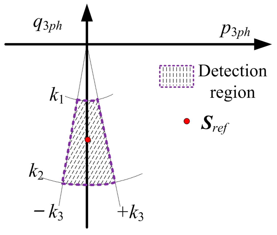
2.2. Islanding Detection Method Based on the Instantaneous Active and Reactive Power at the PCC
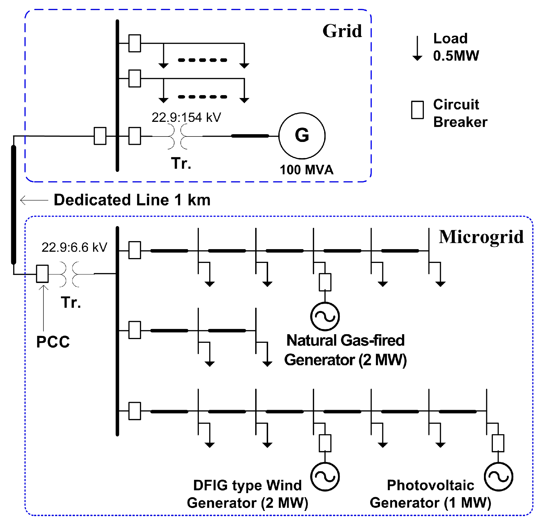
In this subsection, the proposed islanding detection method for an MG based on p3ph and q3ph is described. When the MG is disconnected from the distributed network by opening the circuit breakers at the grid side, p3ph and q3ph will be constant, which depend on the voltages at the PCC as well as the impedance of the dedicated line. p3ph will become almost zero because little resistance exists in the dedicated line. On the other hand, q3ph has some value corresponding to the series inductance and the shunt capacitance of the dedicated line. Since the parameters of the dedicated line can be obtained, these constant active and reactive powers can be easily calculated. Therefore, if the calculated instantaneous active and reactive powers converge to the pre-calculated constant values, the islanding inception will be detected.
Figure 1 shows the islanding detection region. The reference value for the complex power (Sref) is given by
S r e f = | V P C C | 2 Z l i n e *
where, VPCC and Zline* represent the rated line-line voltage of the PCC and the impedance of the dedicated line, respectively.
The criteria of the islanding detection are given by
k 1 | S r e f | | p 2 3 p h + q 2 3 p h | k 2 | S r e f |
S r e f k 3 ° tan 1 q 3 p h p 3 p h S r e f + k 3 °
where k1 and k2 depend on the variation of the voltages at the PCC and the measurement ratio errors of the current transformer (CT) and the potential transformer (PT). The variation of the voltages at the PCC is ±20%, with the fully consideration of the voltage deviation both in the steady-state and the transient state after an islanding inception, and sufficient margin. Thus, k1 and k2 are set by
k 1 = 1.0 × 0.8 × ( 1 3 % ) × ( 1 6 % ) = 0.73
k 2 = 1.0 × 1.2 × ( 1 + 3 % ) × ( 1 + 6 % ) = 1.31
where 1.0, 0.8, 1.2, ±3% and ±6% are respectively per unit value of the rated voltage, lower and upper limits of voltage variation, limits of CT and PT ratio errors [26,27]. In (6), the minimal magnitude of the complex power at the PCC in islanding conditions is calculated when the actual voltages at the PCC are only 80% of the rated voltages considering maximal voltage variation, and the measured currents and voltages at the PCC are respectively 97% and 94% of the actual currents and voltages considering the maximal ratio errors of CTs and PTs. Meanwhile, as shown in (7), the maximal magnitude of the complex power at the PCC in islanding conditions is calculated when the actual voltages at the PCC are 120% of the rated voltages, and the measured currents and voltages at the PCC are respectively 103% and 106% of the actual currents and voltages. k3 is set to be 15°, considering the limits of phase errors of both CTs and PTs, also with sufficient margin [26,27]. These three coefficients, k1, k2 and k3, only depend on the limits of voltage variation and the limits of measurement errors of CTs and PTs defined in the IEC Standards [26,27]. Thus, when the proposed method is applied in another MG, k1, k2 and k3 will not be changed, and only Sref should be pre-calculated considering the parameters of the new dedicated line.
As described above, the islanding will be detected when the trajectory of the point (p3ph, q3ph) moves into the islanding detection region, which is used to prevent the mal-detection for the transient disturbances.

3. Case Studies

An MG, which is connected to a 22.9 kV, 60 Hz distribution network through a Y–Y transformer (22.9/6.6 kV) and a dedicated line (1 km), is shown in Figure 2. The dedicated line is modeled ACSR 58 mm2, whose series resistance, series inductance and shunt capacitance are 0.8316 Ω/km, 0.0022 H/km and 0.0021 μF/km, respectively. The MG is composed of three DGs i.e., a 2 MW natural gas-fired generator, a 2 MW DFIG type wind generator, and a 1 MW photovoltaic generator, and some associated local loads. The system is modeled using the PSCAD/EMTDC simulator, where the sampling rate is 32 samples/cycle. The signals of the currents and voltages measured at the PCC are passed through anti-aliasing RC low-pass filters with the cutoff frequency of 960 Hz, which is half the sampling frequency.
The performance of the proposed islanding detection method is verified under various islanding conditions for the different outputs of the MG, as well as various fault conditions varying the fault position, fault inception angle, fault type and fault impedance, as shown in Table 1 and Table 2. When an islanding incepts, the proposed islanding detecting method should activate the relay as soon as possible; on the contrary, the proposed method should not activate the relay in fault conditions.

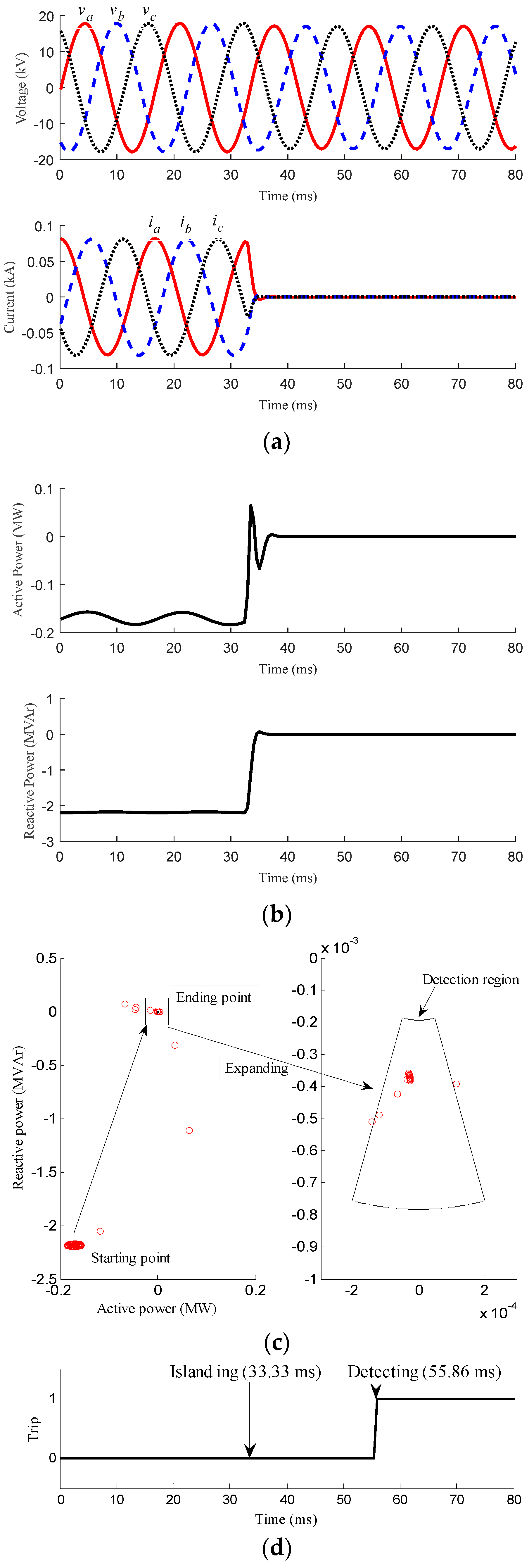
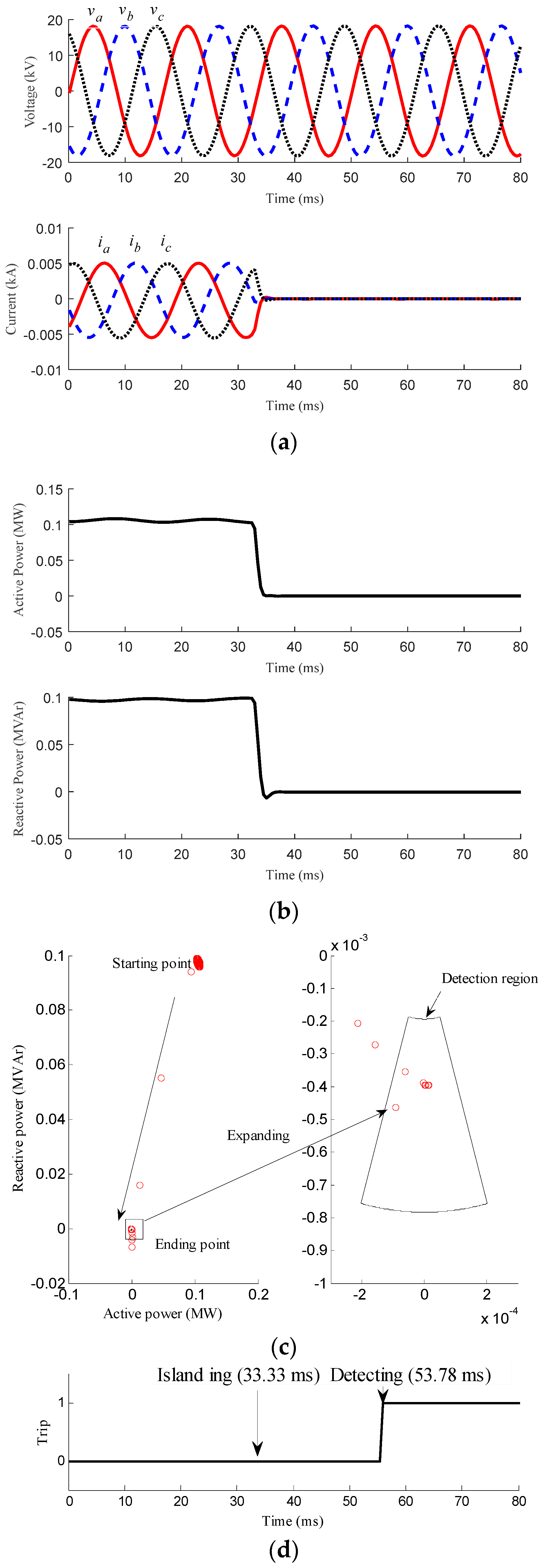
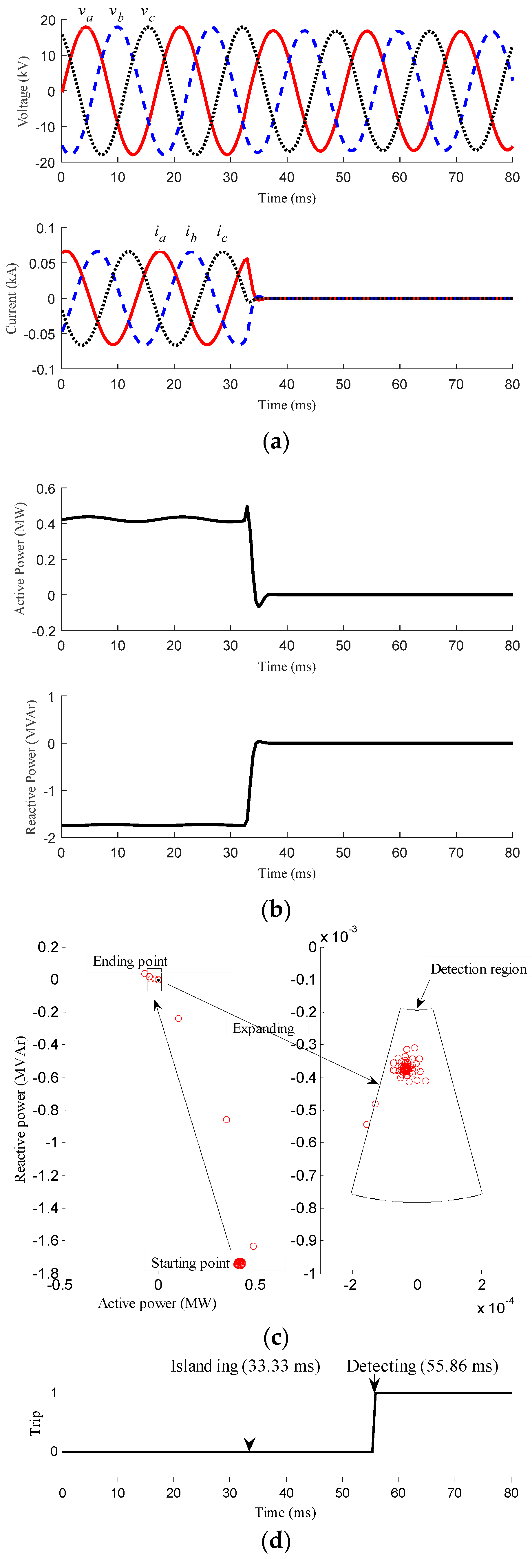
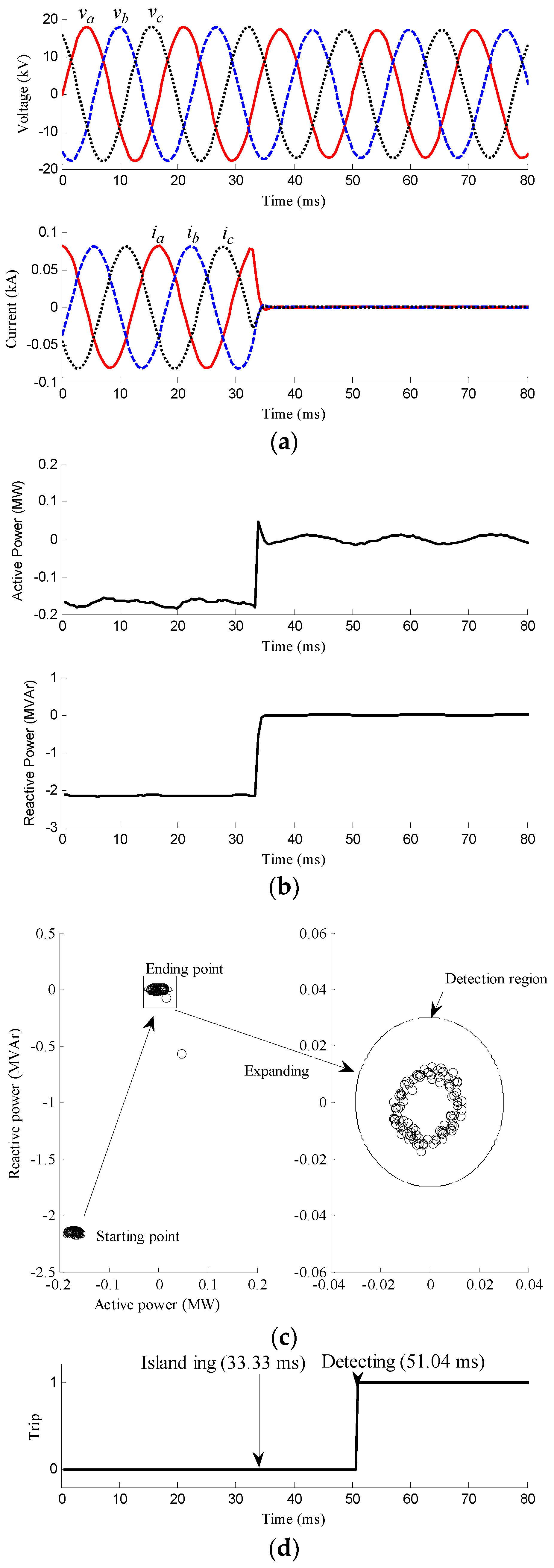
3.1. Islanding Conditions

The performance of the proposed islanding detection method is verified under various islanding conditions for the different outputs of the MG. The results of three cases, where the generating power of the MG is smaller than (Case 1), close to (Case 2) and larger than (Case 3) the local loads, are shown in Figure 3, Figure 4 and Figure 5.
Figure 3 shows the results for Case 1, where the generating power of the MG is smaller than the local loads of the MG. An islanding incepts at 33.33 ms. Figure 3a indicates the voltages and currents measured at the PCC, where va (solid), vb (dashed), and vc (dotted) are shown in the upper subfigure and ia (solid), ib (dashed), and ic (dotted) are shown in the lower subfigure. After the islanding inception, the voltages decrease slightly whilst the currents decrease to nearly zero. p3ph and q3ph are respectively shown in the upper subfigure and lower subfigure of Figure 3b. After islanding inception, p3ph becomes almost zero after a slight fluctuation whilst q3ph becomes a very small value directly. Both p3ph and q3ph change and become stable again in several milliseconds after the island incepts. In Figure 3c, the trajectory of the point (p3ph, q3ph), which is shown with the marks of “o”, is located in the third quadrant prior to the islanding inception. This is because the power is delivered from the grid to the MG prior to the islanding inception, which can also be confirmed in Figure 3b. When the islanding incepts, p3ph is nearly zero and q3ph has the negative value because of the characteristics of the dedicated line. Therefore, the trajectory moves to the islanding detection region. In Figure 3d, where “0” and “1” respectively mean mode of interconnection and islanding, the islanding detection signal is activated at 22.53 ms after the islanding inception. The results indicate that the proposed method can successfully and quickly detect the islanding operation in 1.5 cycles after the islanding inception.
Figure 4 and Figure 5 show the results for Case 2 and 3, where the generating power is close to and larger than the local loads of the MG, respectively. In both cases, an islanding incepts at 33.33 ms. In Case 2, the power transmitted between the MG and the grid prior to the islanding inception is nearly zero. Due to the little variation of the transmitted power in the dedicated line prior to and after the islanding inception, the magnitude and the phase angle of the voltage and the frequency measured at the PCC do not change significantly. However, the proposed method can discriminate the islanding inception from normal load variations by considering the trajectory of the point (p3ph, q3ph). As seen in Figure 4d, the trajectory of the point moves into islanding detection region at 20.45 ms after islanding inception. In Case 3, the generating power of the MG is larger than the local loads of the MG. Thus, the point (p3ph, q3ph) is in the fourth quadrant prior to the islanding inception. As expected, the trajectory of the point (p3ph, q3ph) enters the islanding detection region from the fourth quadrant at 22.53 ms after the islanding inception, as shown in Figure 5c,d.
The results for Cases 1–3 indicate that the proposed method can successfully detect the islanding operation irrespectively of the relationship between the generating power of the MG and its local loads. In addition, the detection speed is much faster than that in [10], almost 1.5 cycle after the islanding incepts.

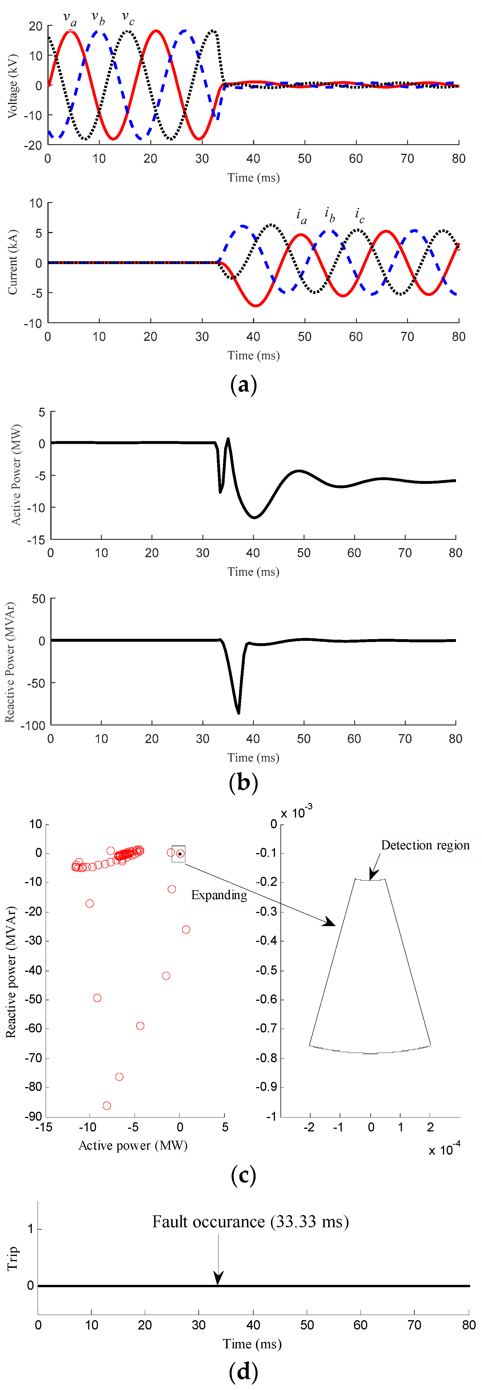
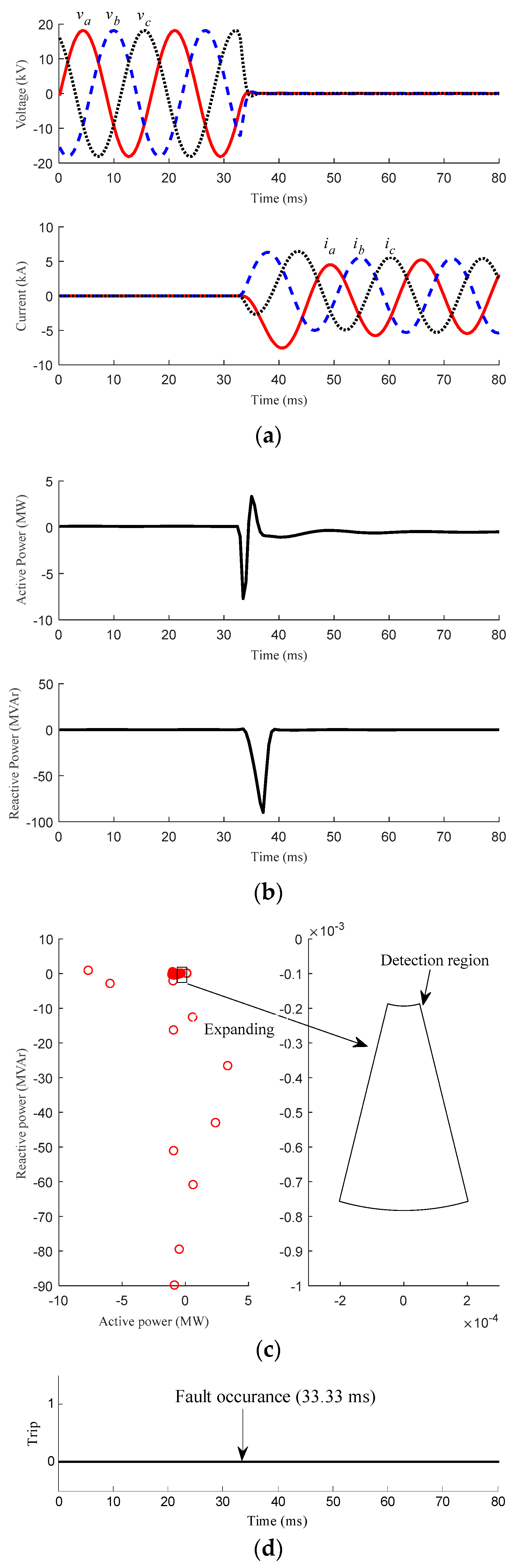
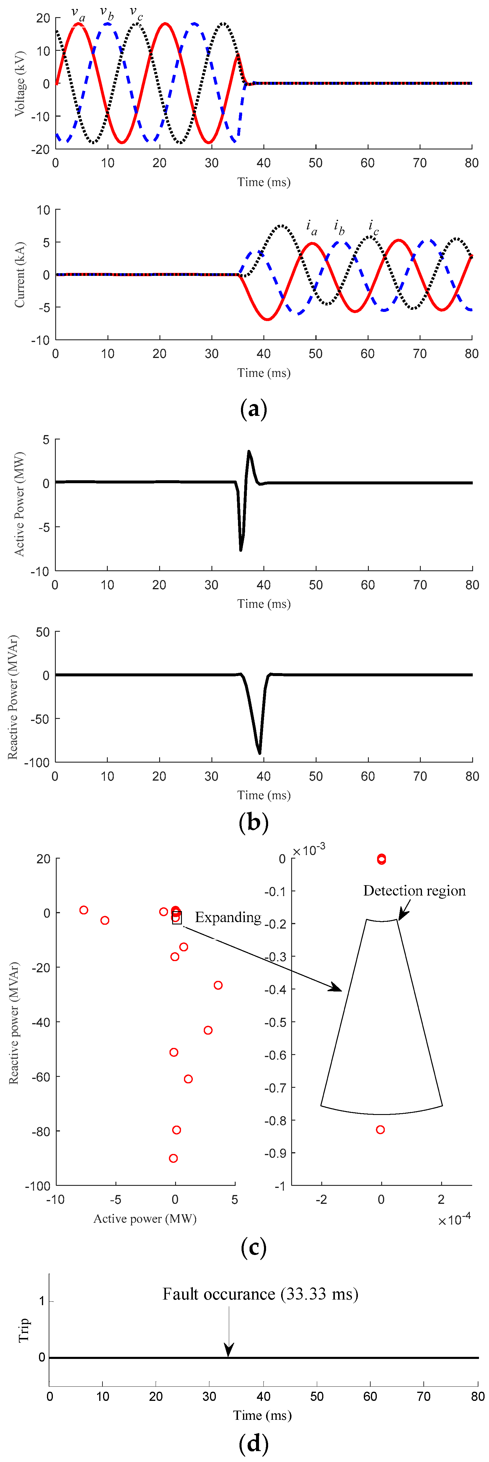
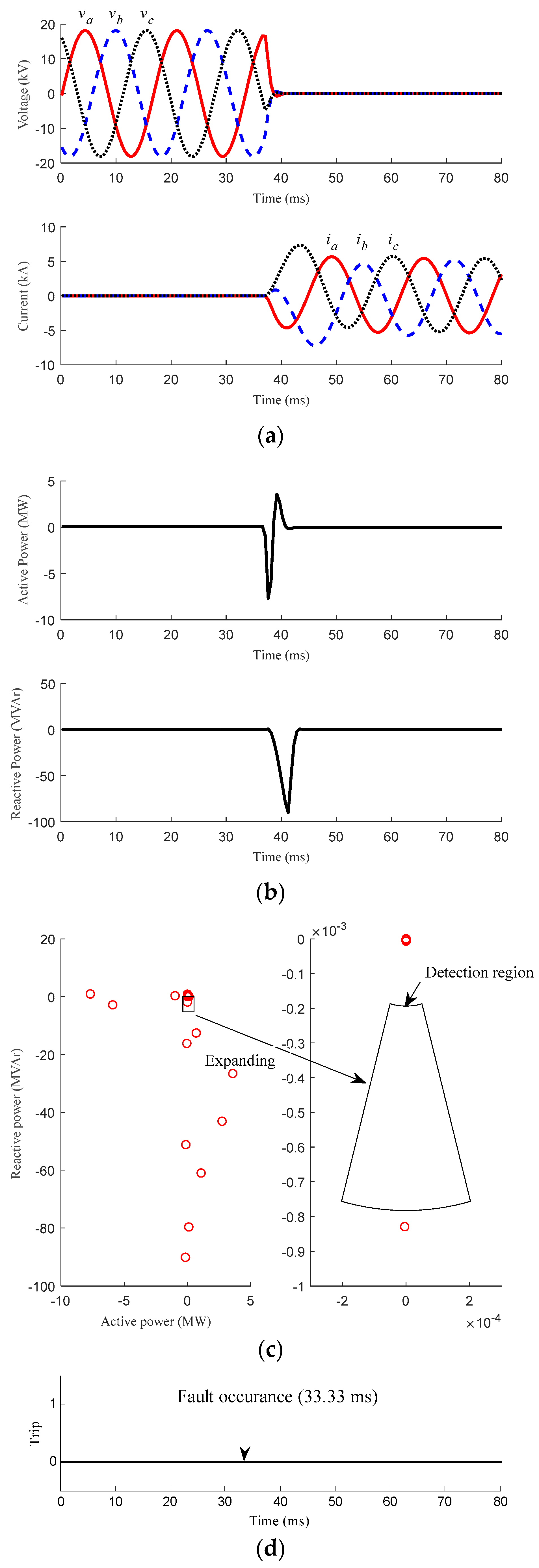
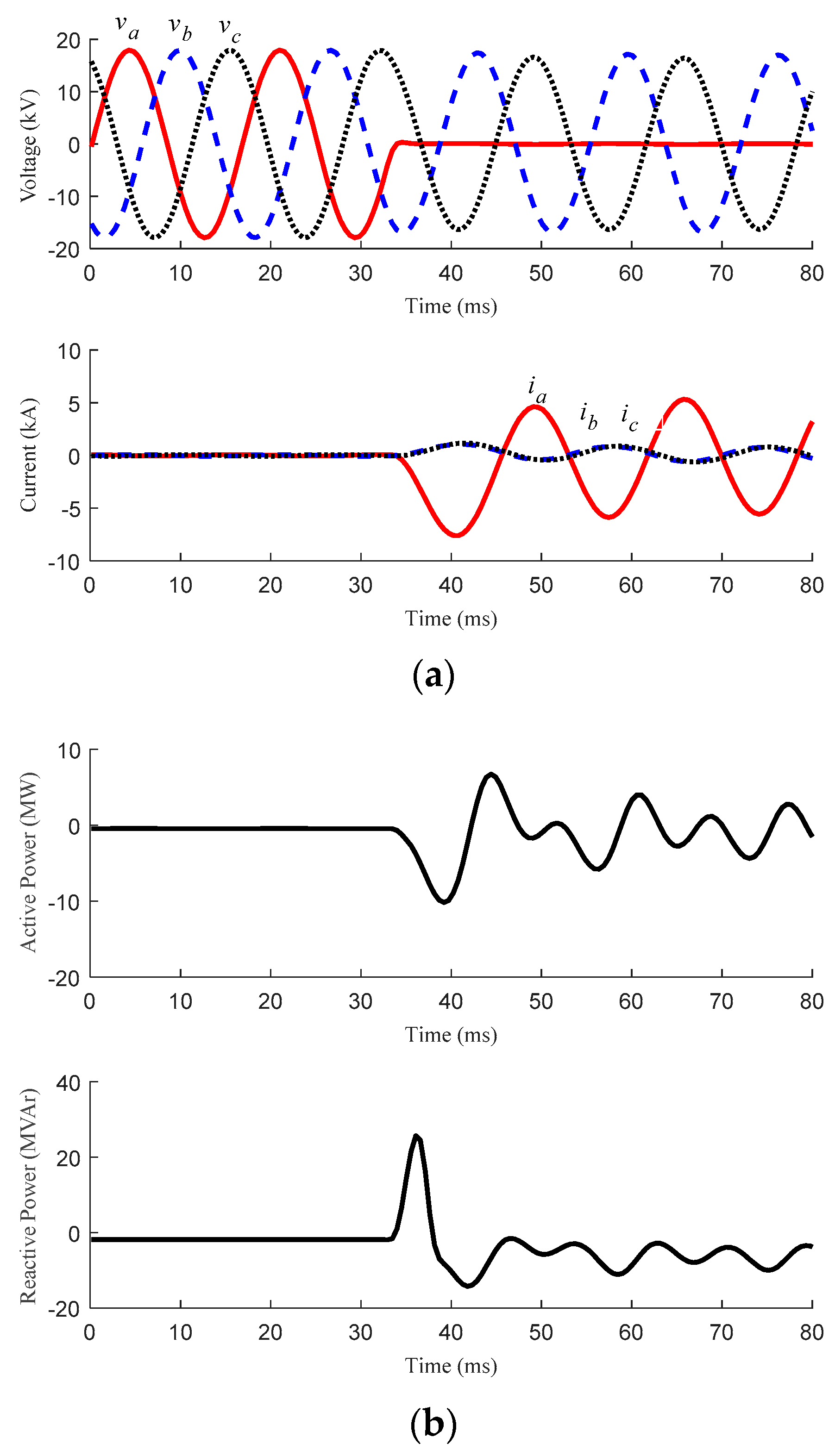
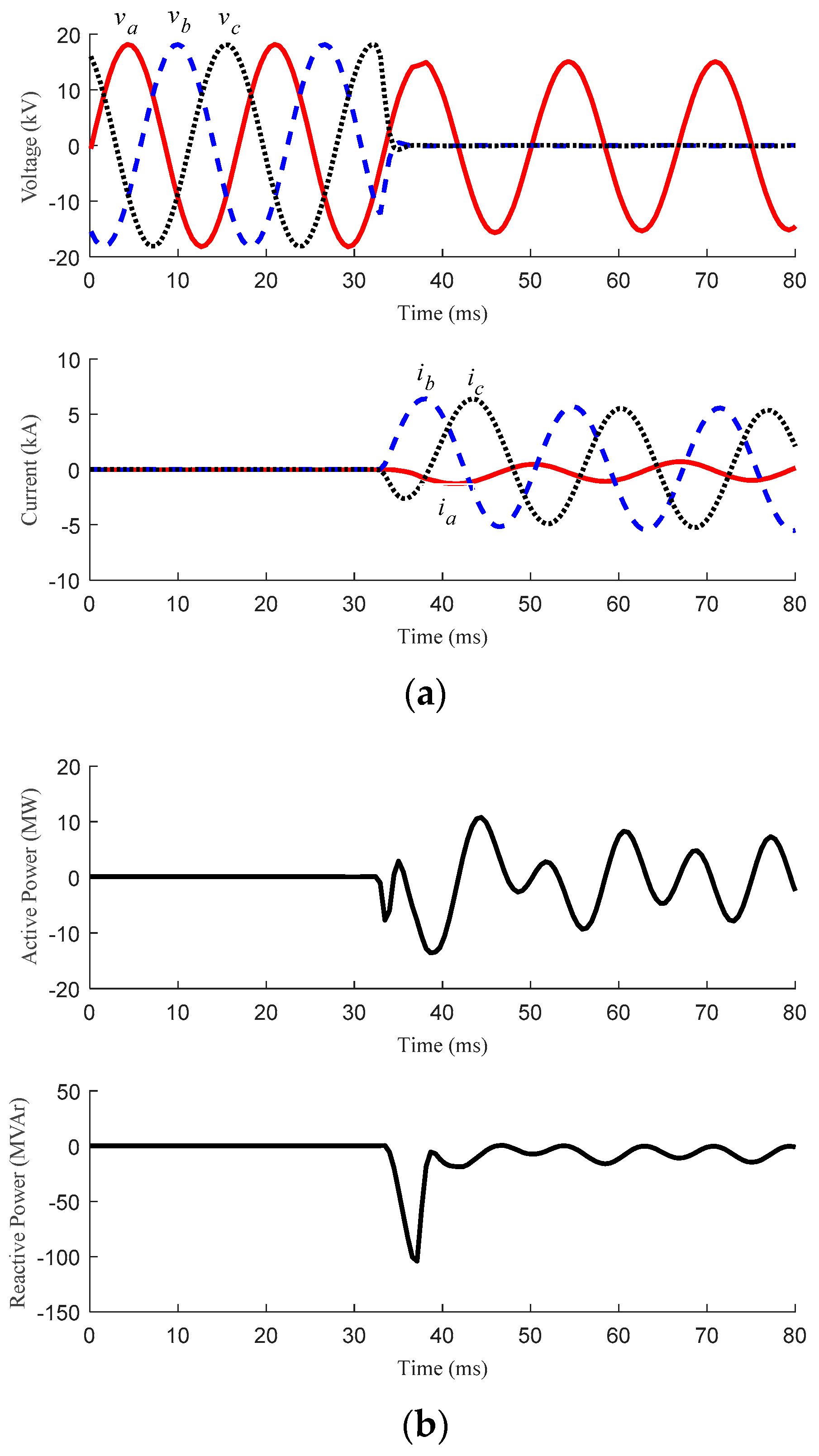
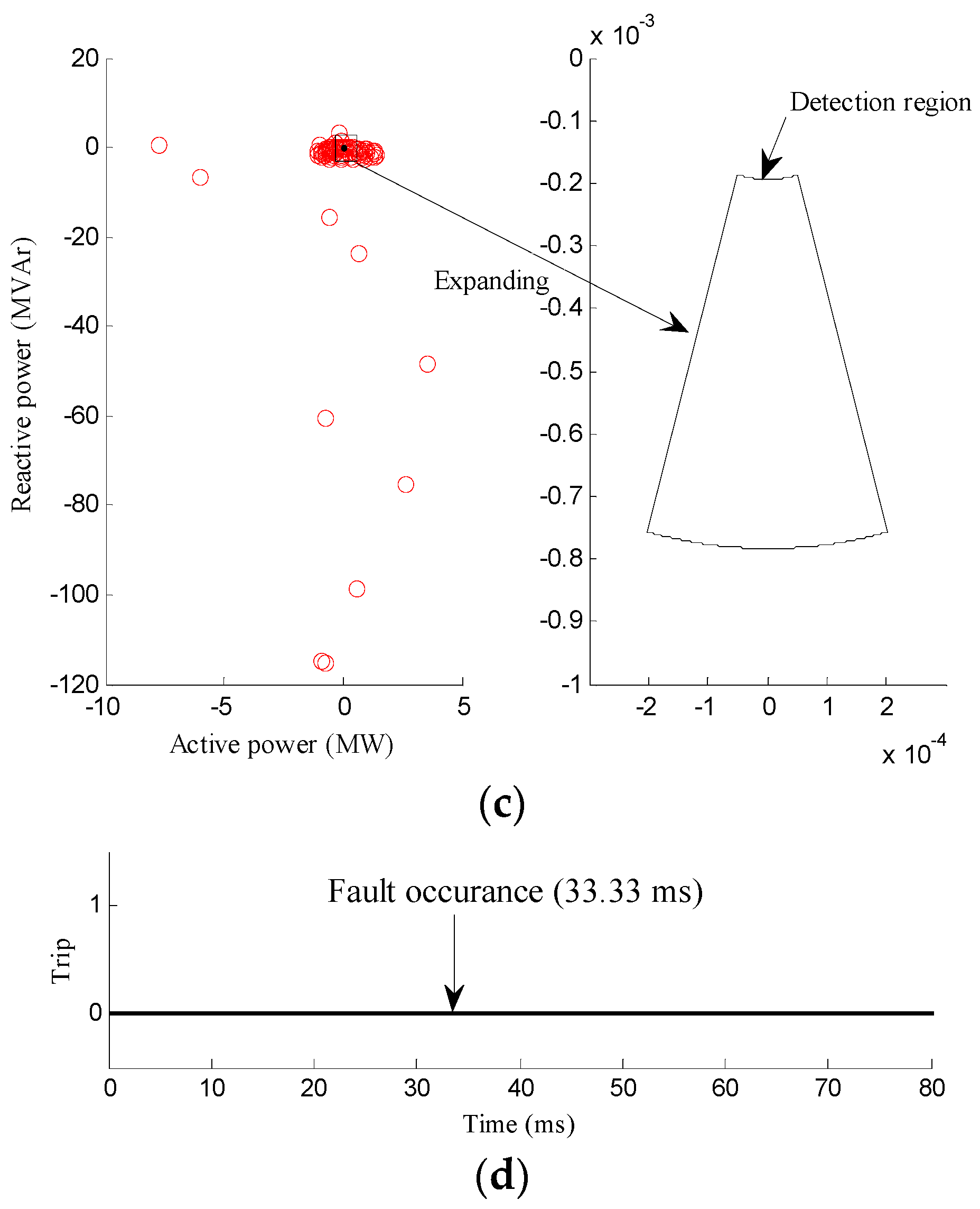
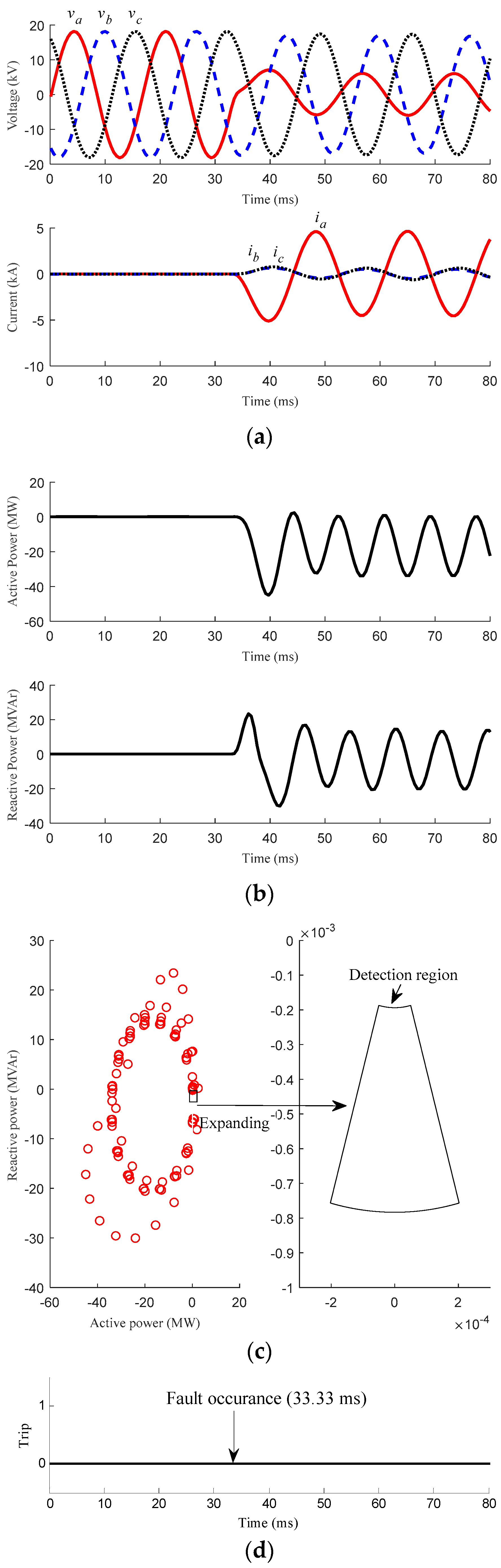
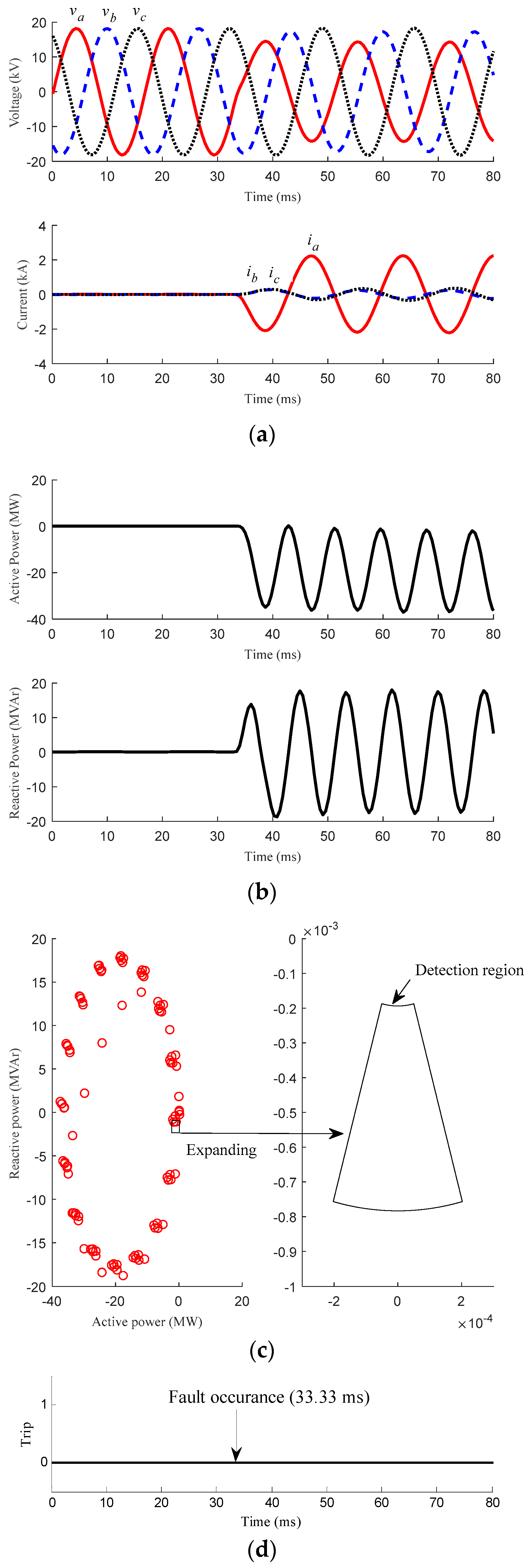
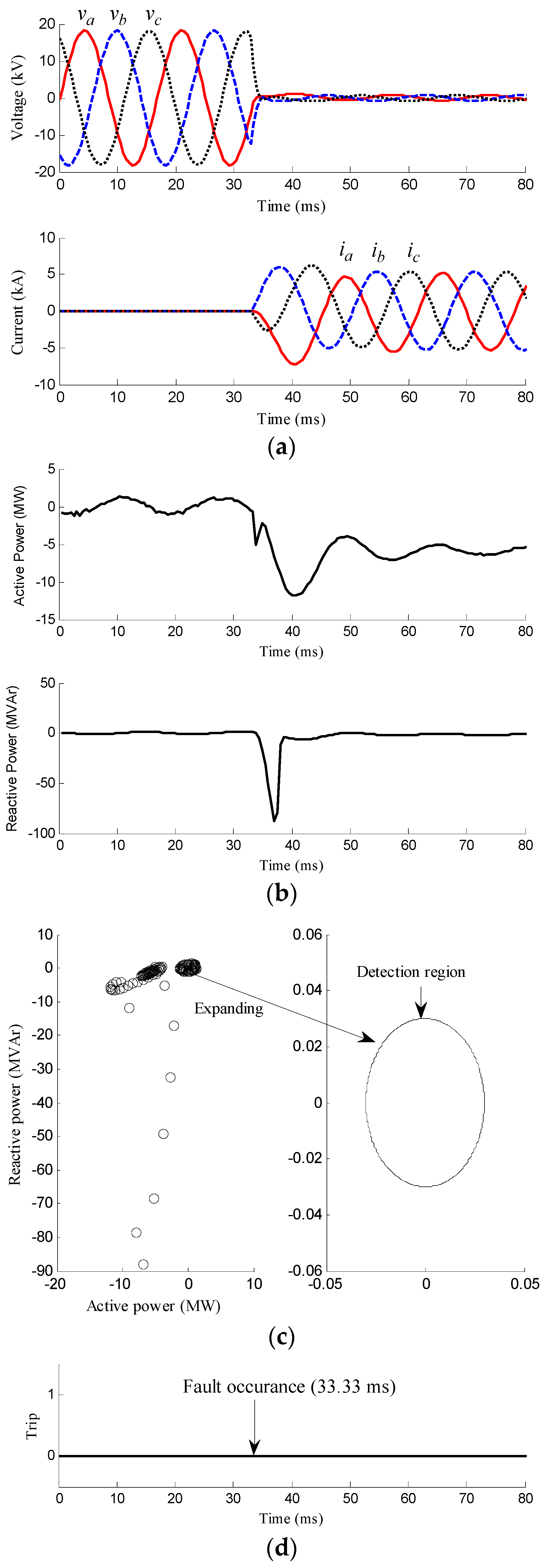
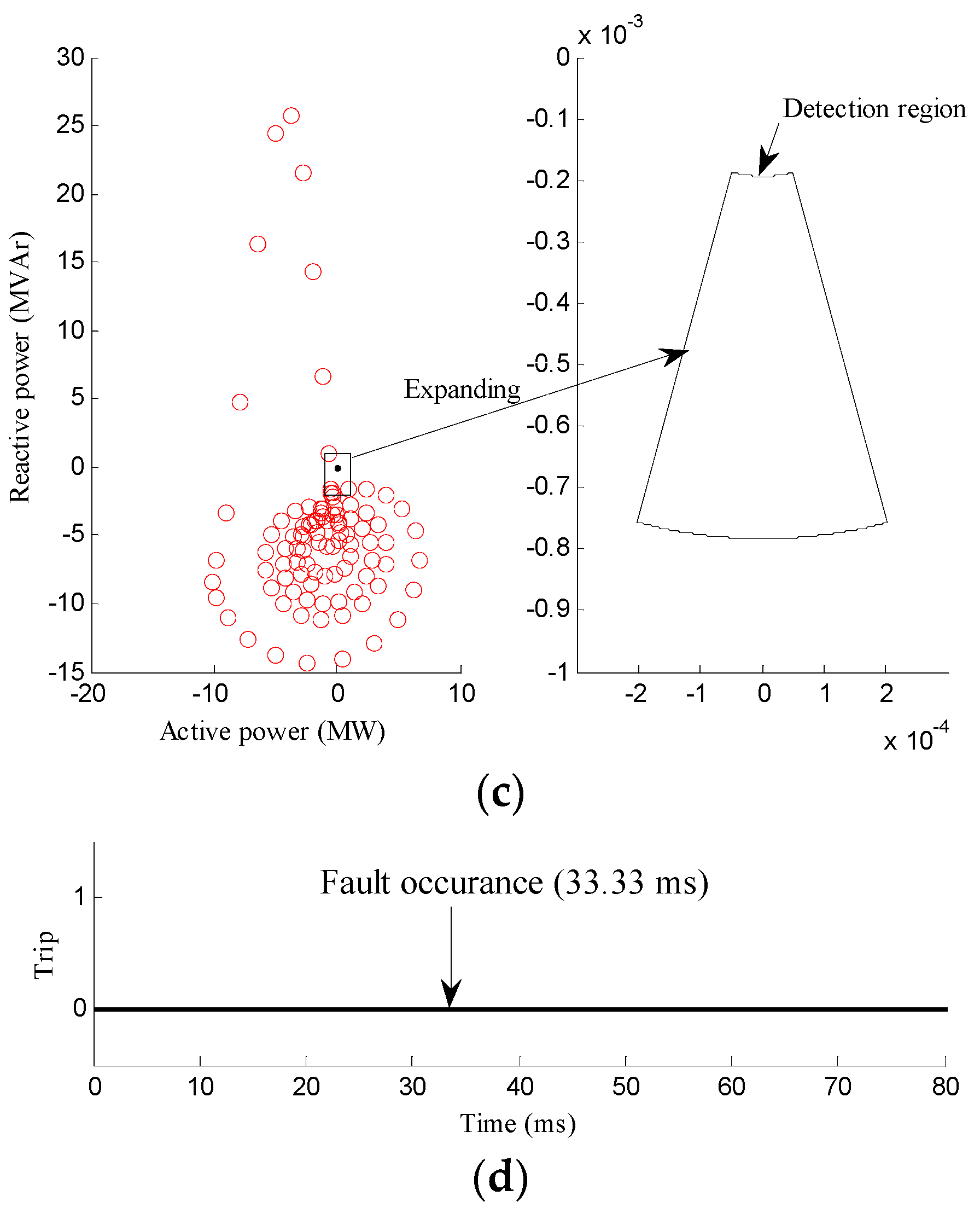
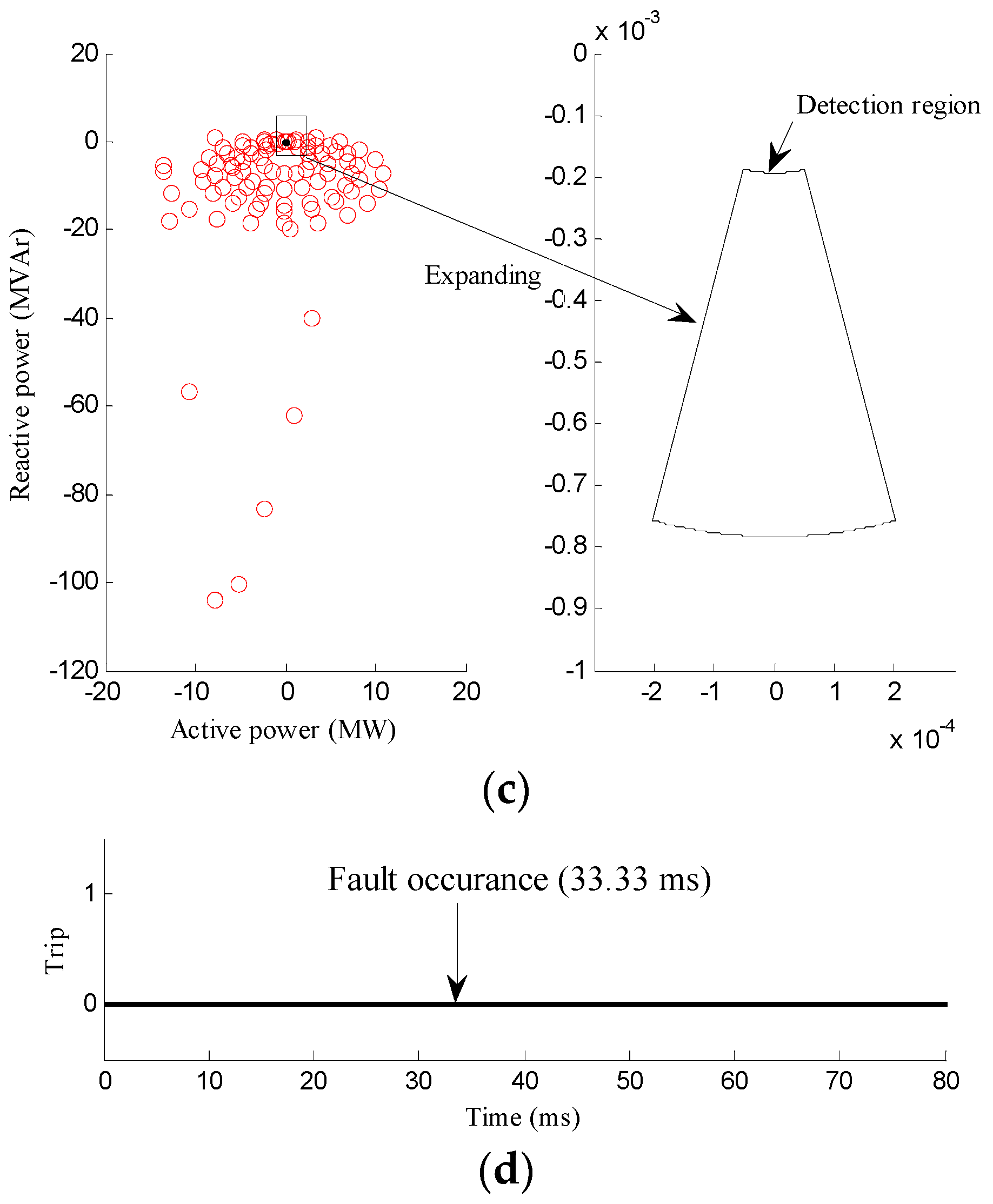
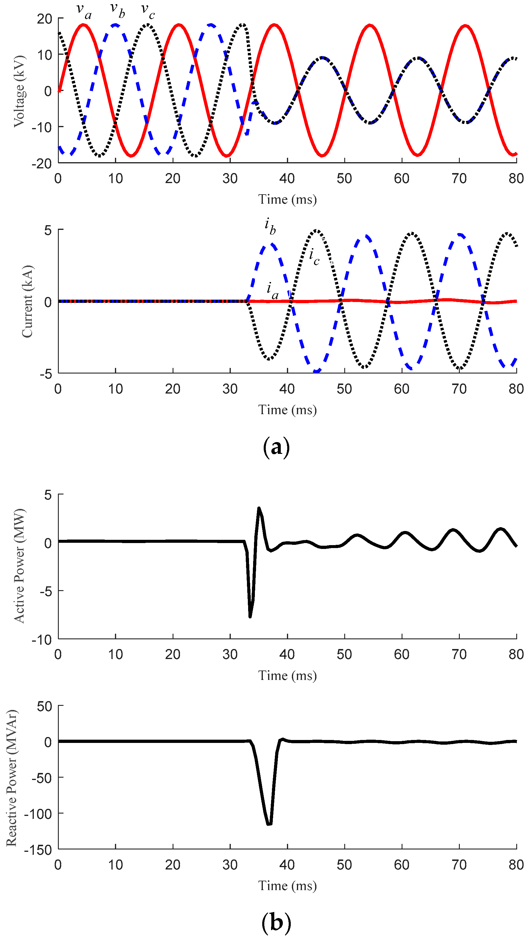
3.2. Fault Conditions

The performance of the proposed islanding detection method is also verified under various fault conditions varying the position and type of the fault. In addition, the qualitative analysis about the effect of the fault inception angle and fault resistance is also included in this subsection. In all these fault cases, the power transmitted between the MG and the grid prior to the fault inception is nearly zero, which is the same as that in Case 2. All faults occur at 33.33 ms, and the proposed method should not activate the islanding detection signal in fault conditions.

3.2.1. Faults with Different Position

In this subsection, three-phase faults, whose inception angles are all 0°, with different position i.e., distribution line of the MG (Case 4) and dedicated line (Case 5) are considered. The results are shown in Figure 6 and Figure 7, respectively.
Figure 6 shows the results for Case 4. In this case, it is assumed that a three-phase fault occurs at the distribution line in the MG. As shown in Figure 6a, the voltages decrease whilst the currents increase sharply when the fault occurs. From Figure 6b,c, both p3ph and q3ph fluctuates after the fault incepts due to the large fault current. The point (p3ph, q3ph) is near the origin prior to the fault inception, since the generating power of the MG is same as the local loads. However, when the fault occurs, the point moves far away the origin, since the fault currents are considerably large. The proposed method does not activate the islanding detection signal (Figure 6d).
Figure 7 shows the results for Case 5, where a three-phase fault occurs at the dedicated line. The results are similar with those for Case 4. The trajectories of the point (p3ph, q3ph) do not move into the islanding detection region, as shown in Figure 7c. Thus, the islanding detection signal is not activated.
The results indicate that the proposed method does not activate the islanding detection signal no matter where a fault occurs.

3.2.2. Faults with Different Inception Angle

In this subsection, three different fault inception angles i.e., 0° (Case 5), 45° (Case 6) and 90° (Case 7) are compared. The fault occurs at the dedicated line at 33.33 ms. The results of Cases 6 and 7 are shown in Figure 8 and Figure 9.
From the results and analysis in the previous subsection, the considerably large fault current is why the point (p3ph, q3ph) moves far away the islanding detection region and consequently inactivates the islanding detection signal. In case of faults with different inception angle, even the magnitudes and waveforms of fault current in Cases 6 and 7 were different from those in Case 5, as seen in Figure 8a and Figure 9a, the fault currents were still considerably large. Finally, the islanding detection signal could not be activated as shown in Figure 8d and Figure 9d.
It can be concluded that the proposed islanding detection method can remain stable no matter when a fault occurs.

3.2.3. Faults with Different Type

In this subsection, four kinds of fault types i.e., single line-to-ground (SLG, Case 8), double line-to-ground (DLG, Case 9), line-to-line (LL, Case 10), and three-phase (3P, Case 5) are considered. The fault occurs at the dedicated line, which is same with that of Case 5. The results of Cases 8−10 are shown in Figure 10, Figure 11 and Figure 12.
Figure 10 shows the results for Case 8, where an A-phase SLG fault occurs. From Figure 10a, the A-phase voltage decreases significantly since the fault occurs very close to the PCC, whilst the voltages of other phases do not change much. The A-phase current increases significantly whilst the currents of other phases increase slightly, compared with the faulted phase, due to the zero-sequence component of the fault current. Due to the unbalanced three-phase voltages and currents, p3ph and q3ph fluctuate even when the transient state is finished, as seen in Figure 10b. Hence, the trajectory of the point (p3ph, q3ph) cannot remain stable at one point and move into the islanding detection region in Figure 10c. In addition, the islanding detection signal is not activated.
Figure 11 and Figure 12 show the results for Cases 9 and 10, where a DLG fault and an LL fault occurs at the dedicated line, respectively. Similar with the results for Case 8, p3ph and q3ph fluctuate in Figure 11b and Figure 12b, and the trajectory of the point (p3ph, q3ph) does not move into the islanding detection region in Figure 11c and Figure 12c. As expected, the islanding detection signal is not activated.
It can be concluded that the proposed islanding detection method can remain stable in fault conditions irrespective of the type of fault.

3.2.4. Faults with Different Fault Impedance

In this subsection, three SLG faults, whose inception angles are all 0°, with different fault impedance i.e., 0 Ω (Case 5), 1 Ω (Case 11) and 5 Ω (Case 12), are analyzed together. The results for Cases 11 and 12 are shown in Figure 13 and Figure 14, respectively.
From the analysis in the previous subsection, when an unbalanced fault i.e., SLG, DLG and LL fault occurs, both p3ph and q3ph fluctuate and the trajectory of the point (p3ph, q3ph) cannot remain stable at one point and move into the islanding detection region. The similar results and analysis can be easily drawn even the fault resistance exists in these unbalanced fault conditions. In addition, fault resistance has no effect on the magnitude and waveform of the fault current in the case of a balanced fault (3P fault). Hence, it could be easily concluded that the fault resistance would not affect the performance of the proposed islanding detection method.
The results for all fault cases indicate that the proposed islanding detection method does not activate the islanding detection signal under various fault scenarios considering different position, inception angle, type and impedance of fault. Hence, the proposed islanding detection method can remain stable as expected in fault conditions, irrespectively of the position, type, inception angle and resistance of a fault.

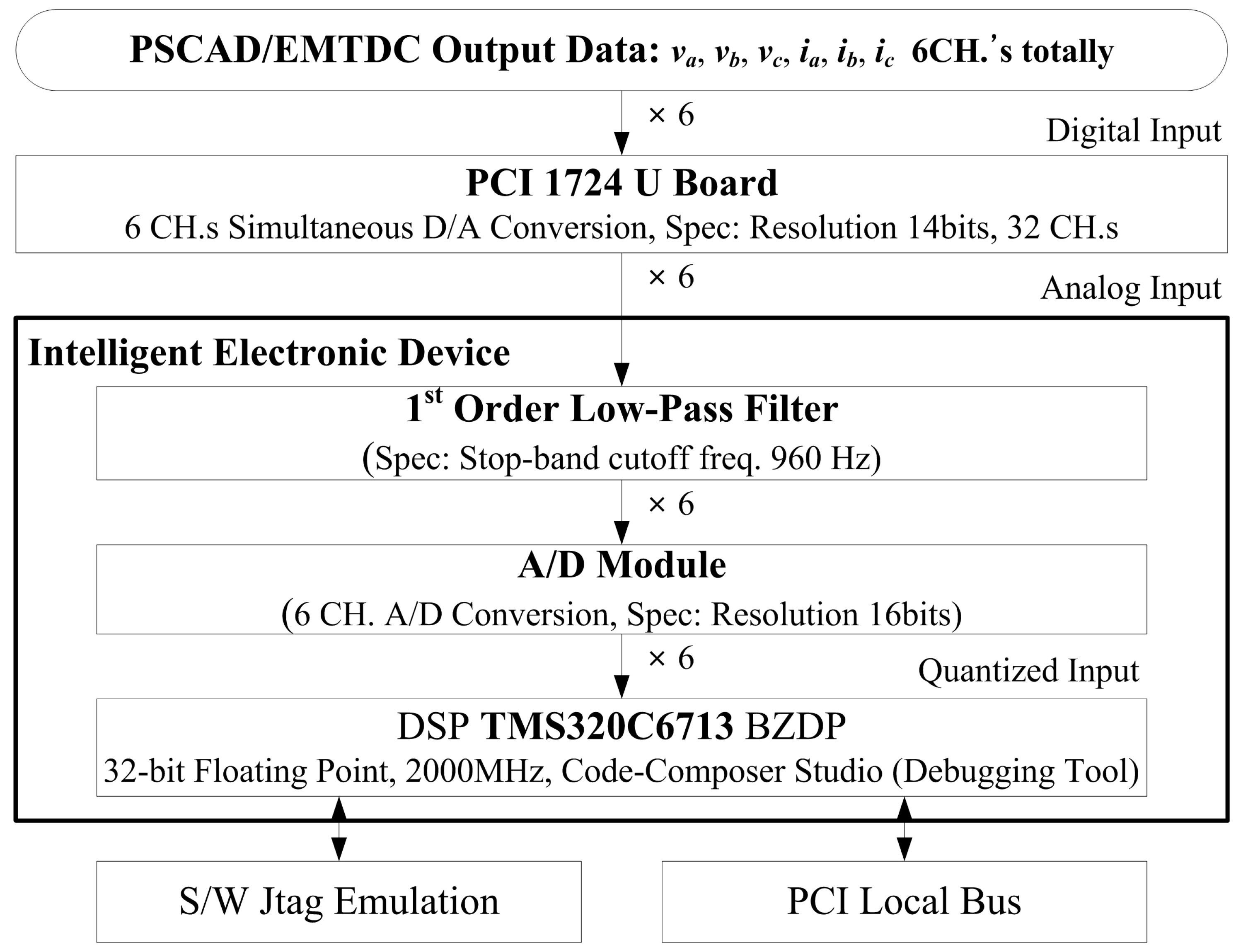
4. Hardware Implementation

Practically, noise signals are contained in real measured three-phase voltage and current signals. As the currents flowing through the PCC in an islanding condition are extremely small, the effect of noise signals of the measured voltages and currents on the performance of the proposed method might not be ignored. Therefore, to verify the performance of the proposed method when noise signals are contained, the method is tested under practical conditions and this section shows the results of hardware implementation of the method into a TMS320C6701 DSP. Figure 15 shows the configuration of hardware implementation. Three-phase voltages and currents generated by PSCAD/EMTDC simulator are converted into analog signals using PCI 1724 U board and then injected into the Intelligent Electronic Device (IED) based on a TMS320C6701 DSP. The signals are then passed through first-order RC filter (fc = 960 Hz) to the 16-bit A/D converters operating at a sampling rate of 32 s/c. All calculation and process of islanding detection are done in the IED.
Figure 16 and Figure 17 show the results of Case 1, in which islanding incepts at 33.33 ms and the islanding detection signal should be activated, and Case 4, in which a 3P fault occurs at 33.33 ms and the islanding detection signal should not be activated. As shown in Figure 16, the point (p3ph, q3ph) cannot remain stable at one point even when the transient state is over. This is because p3ph and q3ph slightly fluctuate due to the noise signals in the voltages and currents. To prevent mal-operation due to these noise signals, the islanding detection region is appropriately expanded and set to be a circle. The results indicate that the proposed method can successfully and fast detect the islanding inception at 17.71 ms after the islanding inception. In Figure 17, even noise signals are contained in real voltage and current signals, the proposed islanding detection method does not activate the islanding detection signal due to large p3ph and q3ph after the fault inception.

5. Conclusions

This paper proposes an islanding detection method for the MG based on the instantaneous active and reactive power delivered from the MG to the dedicated line. The instantaneous active and reactive power are calculated and used to monitor whether the islanding incepts or not. When the circuit breakers at the grid side open, the monitored instantaneous active power from the MG to the dedicated line is converged to nearly zero, whilst the instantaneous reactive power from the MG to the dedicated line has some small value according to the shunt capacitance and the series inductance of the dedicated line. Therefore, the trajectory of the point (p3ph, q3ph) moves into the islanding detection region, and the islanding detection signal is consequently activated. On the contrary, the trajectory of the point (p3ph, q3ph) would move to another point or fluctuates in a fault condition. The islanding detection region can be pre-defined considering the parameters of the dedicated line, variation of the voltage, and the possible measurement errors of CTs and PTs.
The performance of the proposed islanding detection method is verified under various islanding conditions for the different outputs of the MG, as well as various fault conditions varying the position, type, inception angle and resistance of the fault, with the PSCAD/EMTDC generated data. The results indicate that the proposed method can successfully and fast detect the islanding operation irrespective of the relationship between the generating power and the local loads. In addition, the proposed method does not mal-operate irrespectively of the position, type inception angle and resistance of the fault. A prototype relay based on the described scheme successfully detects islanding inception.
The proposed method can correctly and quickly detect the islanding inception. Consequently, the strategies of operation and control of the MG could be re-decided. In addition, the threshold values for the protection relays in the MG could be properly re-set according to the mode of islanding or not, to increase the reliability of the protection system of the MG.

Acknowledgments

This work was supported by the Key Project of Smart Grid Technology and Equipment of National Key Research and Development Plan of China (2016YFB0900600), National Natural Science Foundation of China (Grant No. 51707173) and Technology Projects of State Grid Corporation of China (52094017000W).

Author Contributions

All the authors contributed to publish this paper. Taiying Zheng, Huan Yang and Yong Cheol Kang mainly proposed the proposed scheme. Taiying Zheng, Huan Yang, and Yong Cheol Kang carried out the simulation tests and hardware implementation; Taiying Zheng, Yong Cheol Kang, and Vladimir Terzija revised the original scheme. Writing was done by Taiying Zheng, Huan Yang, Rongxiang Zhao, Yong Cheol Kang, and Vladimir Terzija. Final review was done by all the authors.

Conflicts of Interest

The authors declare no conflict of interest.

References

  1. Ackermann, T.; Andersson, G.; Söder, L. Distributed generation: A definition. Electr. Power Syst. Res. 2001, 57, 195–204. [Google Scholar] [CrossRef]
  2. Chiradeja, P.; Ramakumar, R. An approach to quantify the technical benefits of distributed generation. IEEE Trans. Energy Convers. 2004, 19, 764–773. [Google Scholar] [CrossRef]
  3. Ochoa, L.F.; Padilha-Feltrin, A.; Harrison, G.P. Evaluating distributed generation impacts with a multi objective index. IEEE Trans. Power Deliv. 2006, 21, 1452–1458. [Google Scholar] [CrossRef]
  4. Hatziargyriou, N.; Asano, H.; Iravani, R.; Marnay, C. Microgrids. IEEE Power Energy Mag. 2007, 5, 78–94. [Google Scholar] [CrossRef]
  5. Venkataramanan, G.; Marnay, C. A larger role for microgrids. IEEE Power Energy Mag. 2008, 6, 78–82. [Google Scholar] [CrossRef]
  6. Lasseter, R.; Akhil, A.; Marnay, C.; Stephens, J.; Dagle, J.; Guttromson, R.; Sakis Meliopoulous, A.; Yinger, R.; Eto, J. Integration of Distributed Energy Resources: The CERTS Microgrid Concept; Technical Report for the California Energy Commission: Sacramento, CA, USA, 2002.
  7. Katiraei, F.; Iravani, M.R.; Lehn, P.W. Micro-grid autonomous operation during and subsequent to islanding process. IEEE Trans. Power Deliv. 2005, 20, 248–257. [Google Scholar] [CrossRef]
  8. Jayawarna, N.; Jenkins, N.; Barnes, M.; Lorentzou, M.; Papthanassiou, S.; Hatziargyriou, N. Safety analysis of a microgrid. In Proceedings of the International Conference on Future Power System, Amsterdam, The Netherlands, 16–18 November 2005. [Google Scholar]
  9. Eltawil, M.A.; Zhao, Z. Grid-connected photovoltaic power systems: Technical and potential problems—A review. Renew. Sustain. Energy Rev. 2010, 14, 112–129. [Google Scholar] [CrossRef]
  10. Ahmad, K.N.E.K.; Selvaraj, J.; Rahim, N.A. A review of the islanding detection methods in grid-connected PV inverters. Renew. Sustain. Energy Rev. 2013, 21, 756–766. [Google Scholar] [CrossRef]
  11. Bower, W.; Ropp, M. Evaluation of Islanding Detection Methods for Photovoltaic Utility-Interactive Power Systems; Technical Report IEA PVPS T5-09; International Energy Agency: Paris, France, 2002. [Google Scholar]
  12. Velasco, D.; Trujillo, C.L.; Garcera, G.; Figueres, E. Review of anti-islanding techniques in distributed generators. Renew. Sustain. Energy Rev. 2010, 14, 1608–1614. [Google Scholar] [CrossRef]
  13. Khamis, A.; Shareef, H.; Bizkevelci, E.; Khatib, T. A review of islanding detection techniques for renewable distributed generation systems. Renew. Sustain. Energy Rev. 2013, 28, 483–493. [Google Scholar] [CrossRef]
  14. Yu, B.; Matsui, M.; Yu, G. A review of current anti-islanding methods for photovoltaic power system. Sol. Energy 2010, 84, 745–754. [Google Scholar] [CrossRef]
  15. Xu, W.; Zhang, G.; Li, C.; Wang, W.; Wang, G.; Kliber, J. A power line signaling based technique for anti-islanding protection of distributed generators—Part I: Scheme and analysis. IEEE Trans. Power Deliv. 2007, 22, 1758–1766. [Google Scholar] [CrossRef]
  16. Wang, W.; Kliber, J.; Zhang, G.; Xu, W.; Howell, B.; Palladino, T. A power line signaling based scheme for anti-islanding protection of distributed generators—Part II: Field test results. IEEE Trans. Power Deliv. 2007, 22, 1767–1772. [Google Scholar] [CrossRef]
  17. De Mango, F.; Liserre, M.; Aquila, A.D. Overview of anti-islanding algorithms for PV systems. Part II: Active methods. In Proceedings of the EPE-PEMC, Portorož, Slovenia, 30 August–1 September 2006. [Google Scholar]
  18. Ropp, M.E.; Begovic, M.; Rohatgi, A. Analysis and performance assessment of the active frequency drift method of islanding prevention. IEEE Trans. Energy Convers. 1999, 14, 810–816. [Google Scholar] [CrossRef]
  19. Kobayashi, H.; Takigawa, K.; Hashimoto, E.; Kitamura, A.; Matsuda, H. Method for preventing phenomenon of utility grid with a number of small scale PV systems. In Proceedings of the 22nd IEEE Photovoltaic Specialists Conference, Las Vegas, NV, USA, 7–11 October 1991. [Google Scholar]
  20. Ropp, M.E.; Begovic, M.; Rohatgi, A. Prevention of islanding in grid-connected photovoltaic systems. Prog. Photovolt. 1999, 7, 39–59. [Google Scholar] [CrossRef]
  21. Rioual, P.; Pouliquen, H.; Louis, J. Regulation of a PWM rectifier in the unbalanced network state using a generalized model. IEEE Trans. Power Electron. 1996, 11, 495–502. [Google Scholar] [CrossRef]
  22. Song, H.; Nam, K. Dual current control scheme for PWM converter under unbalanced input voltage conditions. IEEE Trans. Ind. Electron. 1999, 46, 953–959. [Google Scholar] [CrossRef]
  23. Stankovic, A.M.; Lev-Ari, H. Frequency-domain observations on definitions of reactive power. IEEE Power Eng. Rev. 2000, 20, 46–48. [Google Scholar] [CrossRef]
  24. Suh, Y.S.; Tijeras, V.; Lipo, T.A. A control method in dq synchronous frame for PWM boost rectifier under generalized unbalanced operating conditions. In Proceedings of the IEEE PESC, Cairns, Australia, 23–27 June 2002. [Google Scholar]
  25. Suh, Y.S.; Lipo, T.A. Control scheme in hybrid synchronous stationary frame for PWMAC/DC converter under generalized unbalanced operating conditions. IEEE Trans. Ind. Appl. 2006, 42, 825–835. [Google Scholar]
  26. International Electrotechnical Commission. Instrument Transformers—Part 1: Current Transformers; IEC 60044-1:2003; International Electrotechnical Commission: Geneva, Switzerland, 2003. [Google Scholar]
  27. International Electrotechnical Commission. Instrument Transformers—Part 2: Inductive Voltage Transformers; IEC 60044-2:2003; International Electrotechnical Commission: Geneva, Switzerland, 2003. [Google Scholar]
Figure 1. Islanding detection region.
Energies 11 00323 g001
Figure 2. Single-line diagram of the model system.
Energies 11 00323 g002
Figure 3. Results for Case 1. (a) va,b,c (upper) and ia,b,c (lower); (b) p3ph (upper) and q3ph (lower); (c) Trajectories of the point (p3ph, q3ph); (d) Islanding detection signal.
Energies 11 00323 g003
Figure 4. Results for Case 2. (a) va,b,c (upper) and ia,b,c (lower); (b) p3ph (upper) and q3ph (lower); (c) Trajectories of the point (p3ph, q3ph); (d) Islanding detection signal.
Energies 11 00323 g004
Figure 5. Results for Case 3. (a) va,b,c (upper) and ia,b,c (lower); (b) p3ph (upper) and q3ph (lower); (c) Trajectories of the point (p3ph, q3ph); (d) Islanding detection signal.
Energies 11 00323 g005
Figure 6. Results for Case 4. (a) va,b,c (upper) and ia,b,c (lower); (b) p3ph (upper) and q3ph (lower); (c) Trajectories of the point (p3ph, q3ph); (d) Islanding detection signal.
Energies 11 00323 g006
Figure 7. Results for Case 5. (a) va,b,c (upper) and ia,b,c (lower); (b) p3ph (upper) and q3ph (lower); (c) Trajectories of the point (p3ph, q3ph); (d) Islanding detection signal.
Energies 11 00323 g007
Figure 8. Results for Case 6. (a) va,b,c (upper) and ia,b,c (lower); (b) p3ph (upper) and q3ph (lower); (c) Trajectories of the point (p3ph, q3ph); (d) Islanding detection signal.
Energies 11 00323 g008
Figure 9. Results for Case 7. (a) va,b,c (upper) and ia,b,c (lower); (b) p3ph (upper) and q3ph (lower); (c) Trajectories of the point (p3ph, q3ph); (d) Islanding detection signal.
Energies 11 00323 g009
Figure 10. Results for Case 8. (a) va,b,c (upper) and ia,b,c (lower); (b) p3ph (upper) and q3ph (lower); (c) Trajectories of the point (p3ph, q3ph); (d) Islanding detection signal.
Energies 11 00323 g010aEnergies 11 00323 g010b
Figure 11. Results for Case 9. (a) va,b,c (upper) and ia,b,c (lower); (b) p3ph (upper) and q3ph (lower); (c) Trajectories of the point (p3ph, q3ph); (d) Islanding detection signal.
Energies 11 00323 g011aEnergies 11 00323 g011b
Figure 12. Results for Case 10. (a) va,b,c (upper) and ia,b,c (lower); (b) p3ph (upper) and q3ph (lower); (c) Trajectories of the point (p3ph, q3ph); (d) Islanding detection signal.
Energies 11 00323 g012aEnergies 11 00323 g012b
Figure 13. Results for Case 11. (a) va,b,c (upper) and ia,b,c (lower); (b) p3ph (upper) and q3ph (lower); (c) Trajectories of the point (p3ph, q3ph); (d) Islanding detection signal.
Energies 11 00323 g013
Figure 14. Results for Case 12. (a) va,b,c (upper) and ia,b,c (lower); (b) p3ph (upper) and q3ph (lower); (c) Trajectories of the point (p3ph, q3ph); (d) Islanding detection signal.
Energies 11 00323 g014
Figure 15. Configuration of hardware implementation.
Energies 11 00323 g015
Figure 16. Hardware implementation results for Case 1. (a) va,b,c (upper) and ia,b,c (lower); (b) p3ph (upper) and q3ph (lower); (c) Trajectories of the point (p3ph, q3ph); (d) Islanding detection signal.
Energies 11 00323 g016
Figure 17. Hardware implementation results for Case 4. (a) va,b,c (upper) and ia,b,c (lower); (b) p3ph (upper) and q3ph (lower); (c) Trajectories of the point (p3ph, q3ph); (d) Islanding detection signal.
Energies 11 00323 g017
Table 1. Islanding scenarios.
ScenarioCase No.DescriptionFigureDetection Signal
IslandingCase 1Generating power of the MG < local loads of the MGFigure 3Should be activated
Case 2Generating power of the MG ≈ local loads of the MGFigure 4
Case 3Generating power of the MG > local loads of the MGFigure 5
Table 2. Fault scenarios.
ScenarioCase No.Fault PositionFault Inception AngleFault TypeFault ImpedanceFigureDetection Signal
FaultCase 4Distribution line of the MGThree-phase0 ΩFigure 6Should NOT be activated
Case 5Dedicated lineThree-phase0 ΩFigure 7
Case 6Dedicated line45°Three-phase0 ΩFigure 8
Case 7Dedicated line90°Three-phase0 ΩFigure 9
Case 8Dedicated lineSingle line-to-ground0 ΩFigure 10
Case 9Dedicated lineDouble line-to-ground0 ΩFigure 11
Case 10Dedicated lineLine-to-line0 ΩFigure 12
Case 11Dedicated lineSingle line-to-ground1 ΩFigure 13
Case 12Dedicated lineSingle line-to-ground5 ΩFigure 14

