AC-Chopper-Based Inrush Current Suppressor in a Wind Power Generation System with Squirrel-Cage Induction Machines

1
Graduate School of Science and Engineering, Yamaguchi University, 2-16-1, Tokiwadai Ube City 755-8611, Japan
2
Department of Electrical Engineering, National Institute of Technology, Ube College, 2-14-1, Tokiwadai Ube City 755-8555, Japan
*
Author to whom correspondence should be addressed.
†
These authors contributed equally to this work.
Energies 2018, 11(2), 397; https://doi.org/10.3390/en11020397
Submission received: 5 January 2018
/
Revised: 3 February 2018
/
Accepted: 6 February 2018
/
Published: 8 February 2018
(This article belongs to the Section F: Electrical Engineering)
Abstract
:This paper proposes the inrush current suppressor using an AC chopper in a large-capacity wind power generation system (WPGS) with two squirrel-cage induction machines (SCIMs), which are switched over depending on the wind speed. The input side of the AC chopper is connected to the source in parallel. The output side of the AC chopper is connected in series with the SCIM through matching transformers. In the proposed inrush current suppressor, the output voltage of the AC chopper is the same as the receiving-end voltage before connecting the SCIM. By gradually decreasing the output voltage of the AC chopper, the applied voltage of the SCIM is gradually increased without the inrush current. The basic principle of the proposed inrush current suppressor is discussed in detail. A computer simulation is implemented to confirm the validity and practicability of the proposed inrush current suppressor using a power system computer-aided design/electromagnetic transients including DC (PSCAD/EMTDC). Simulation results demonstrate that the proposed inrush current suppressor can suppress the inrush current.
1. Introduction
The demand for energy in the world continues to increase yearly. The use of renewable energy is crucial for solving the demand for energy. The total cumulative capacity of wind power generation systems (WPGS) had reached 486.8 GW in 2016 [1]. Many papers focused on WPGS have been published [2,3,4]. Squirrel-cage induction machines (SCIMs) are already used and installed because of their reliability and low cost. In large-capacity WPGS, two generators are switched over depending on the wind speed. The SCIM has an inrush current of approximately six-times the rated current at the start-up condition, because it does not have an excitation source [5]. This inrush current causes a voltage sag in the power system. As is well known, voltage sag affects the equipment on the grid, such as the adjustable-speed motor, high-voltage discharge lamp and magnetic switch. The Agency for Natural Resources and Energy in the Ministry of Economy, Trade and Industry, Japan, has issued a guideline for grid-connection requirements for ensuring power quality [6]. This guideline recommends that the voltage sag be within ±10% and the suppressing time within 2 s of connecting the SCIM.
The mitigation methods of inrush currents have been proposed [7,8,9,10,11]. Typically, a soft-starter, which consists of reverse-parallel-connected thyristors, is used to limit the inrush current in WPGSs [7,8]. However, a soft starter generates harmonic currents from the switching of thyristors. A method for compensating harmonic currents using a shunt active filter has been proposed to avoid the harmonic currents caused by the soft-starter [9,11]. In this method, a pulse width modulation (PWM) converter, which performs as the shunt active filter, compensates both the harmonic currents and the fundamental reactive power. However, a large-capacity PWM converter, with a rating as high as 70% of the SCIM rating of the wind turbine, is necessary, because the PWM converter directly supplies the fundamental reactive power generated by the SCIM in both the steady state and transient state. In [12], a compensating method for harmonic currents generated by a soft starter using a hybrid active power filter has been proposed. This method can compensate the harmonic current with a small-capacity hybrid active filter. However, the calculation is complex, and the control range of power factor is narrow because of the fixed phase-leading capacity. In [13], a method of connecting resistors in series with the induction machine has been proposed. This method can suppress the inrush current by a simple composition without harmonic currents. However, the series-connected resistors have large energy losses in the inrush current suppression.
We have proposed the inrush current suppressor in a WPGS with a 2.2-kW SCIM using a matrix converter (MC) [14]. The input side of the MC is connected in parallel to the power system. The output side of the MC is connected in series with the induction machine through matching transformers. The output voltage of the MC is determined by multiplying the control gain and the SCIM current. This means that the output side of the MC performs as the resistor. In [14], the proposed inrush current suppressor suppresses the inrush current. However, the total harmonic distortion (THD) was high because of the switching ripple current of the MC. In [15,16], the direct duty ratio pulse width modulation (DDRPWM) method [17] is used for the proposed inrush current suppressor. The DDRPWM method decides the duty ratio by simple equations. The switching ripple of the input current of the MC is low because all input phases are used in one switching cycle. A computer simulation was implemented to confirm the validity of the proposed MC-based inrush current suppressor. The authors confirmed that the proposed MC-based inrush current suppressor can suppress the inrush currents for 100-kW and 400-kW SCIMs. However, the maximum THD value of the source current was approximately 20% of the previously-proposed inrush current suppressor. Moreover, the controller for an MC-based inrush current suppressor is complicated. It is necessary to simplify the inrush current suppressor with low THD for practical use. Nevertheless, the doubly-fed induction generator (DFIG)-based WPGSs for overcoming the voltage sag have been proposed [18,19,20]. In [18], the voltage-source inverter for compensating the voltage sag on a grid is connected between the grid and DFIG. The controller for the inverter has a voltage sag detector and fuzzy controller. In [19,20], the design and analysis of a fault ride-through on a grid were presented. Our study is different in that the inrush current suppressor prevents the occurrence of voltage sag by the inrush currents generated by the SCIM connection.
This paper proposes the inrush current suppressor using an AC chopper in a large-capacity WPGS with two SCIMs. In the proposed inrush current suppressor, an AC chopper is used because it can control the effective value of the output voltage in a simple way [21]. The switching pulses of the AC chopper are generated by the commonly-used triangular-wave comparison PWM method. Thus, the controller of the proposed method can be used in inexpensive processors. In this work, two SCIMs, rated 100 kW and 400 kW, are switched over depending on the wind speed. The input side of the AC chopper is connected in parallel to the power system. The output side of the AC chopper is connected in series with the SCIM through matching transformers. In the proposed inrush current suppressor, the output voltage of the AC chopper is the same as the receiving-end voltage before connecting the SCIM. By gradually decreasing the output voltage of the AC chopper, the voltage applied to the SCIM is gradually increased to suppress the inrush current. As a result, the proposed AC chopper-based inrush current suppressor behaves as a soft starter without harmonic currents. The basic principle of the proposed AC chopper-based inrush current suppressor is discussed in detail. A computer simulation is implemented to confirm the validity of the proposed AC chopper-based inrush current suppressor using the power system transient analysis simulator known as the power system computer-aided design/electromagnetic transients including DC (PSCAD/EMTDC). The simulation results demonstrate that the proposed AC chopper-based inrush current suppressor suppresses the inrush currents perfectly.
The main contributions of this paper are as follows:
- Simplified controller compared to the previously-proposed MC-based inrush current suppressor.
- Improved THD, notch depth and area during the start of the SCIMs.
- Comparison of the energy losses for the previous and proposed inrush current suppressors under two wind speed profiles.
2. Inrush Current Suppressor Using AC Chopper
Figure 1 shows the system configuration with the proposed inrush current suppressor using an AC chopper in a large-capacity WPGS. , and are AC switches that consist of anti-parallel connected thyristors. In this study, two SCIMs, rated 100 kW and 400 kW, are switched over depending on the wind speed. The cut-in wind speed is 3 m/s, and the cut-out wind speed is 25 m/s in a general large-capacity WPGS. The 100-kW SCIM is connected to the power system when the wind speed is from 3 m/s–8 m/s, and the 400-kW SCIM is connected to the power system when the wind speed is from 8.0001 m/s–25 m/s. In the proposed inrush current suppressor, an AC chopper is used because it can control the effective value of the output voltage in a simple way. The AC chopper consists of six switches per single-phase [21]. The capacitor performs as a switch snubber and filter. The input side of the AC chopper is connected in parallel to the power system. The output side of the AC chopper is connected in series with the SCIM through matching transformers. The input side of the AC chopper is connected to a low-pass filter to reduce the switching ripple. When the output voltage of the AC chopper is zero, is used to short the inrush current suppressor for the power loss reduction during the normal operation of the SCIMs.
The AC chopper can drive the buck and boost chopper modes. The buck chopper mode is used in this paper. The PWM pulses are generated by comparing the reference value and triangular wave. The amplitude of the triangular wave is from 0 to −1. The output voltage of the AC chopper can be controlled by the reference value . The effective value of the output voltage of an AC chopper is given by:
where is the effective value of the input voltage of an AC chopper and d is the duty ratio. In this work, the turn ratio of the matching transformer is 1:4. Thus, the effective value of the output voltage of the AC chopper is the same as the receiving-end voltage when is −0.75. In the proposed inrush current suppressor, the output voltage of the AC chopper is the same as the receiving-end voltage before connecting the SCIM. By gradually decreasing the output voltage of the AC chopper, the voltage applied to the SCIM is gradually increased to suppress the inrush current. Figure 2 shows the single-phase equivalent circuit of Figure 1. is the receiving-end voltage; is the output voltage of AC chopper; and is the SCIM voltage. Applying Kirchhoff’s voltage law to the circuit in Figure 2 gives the following equation:
Therefore, immediately after the SCIM is connected to the grid, the SCIM voltage becomes zero by setting the output voltage of the AC chopper to . Subsequently, the SCIM voltage is gradually increased by decreasing the output voltage of the AC chopper . The previously-proposed MC-based inrush current suppressor, which can control the amplitude and phase angle of the output voltage, behaves as resistors to the SCIM currents. The proposed method is different in that the AC chopper increases the applied voltage of the SCIMs slightly.
Figure 3 shows the relationship between the effective values with the proposed AC chopper-based inrush current suppressor. The initial value of is the same as . At this time, the applied voltage is zero. Thus, no inrush current occurs. is reduced to zero within two seconds after connecting the SCIM, as the guideline for grid connection for ensuring power quality [6] recommends a suppression time of within 2 s of connecting the SCIM. Therefore, the proposed AC chopper-based inrush current suppressor acts as the soft starter with no harmonic current.
3. Simulation Results
All simulations are carried out using the PSCAD/EMTDC to verify the effectiveness of the proposed AC chopper-based inrush current suppressor.
Table 1 lists the parameters of the SCIMs. In all simulations, the source side inductor is 0.1 mH, which is approximately 5% relative to the rated impedance of the 400-kW SCIM. The source voltage is 480 Vrms, and the source frequency is 50 Hz. In this simulation, the wind turbine model on the PSCAD/EMTDC is used. The air density is 1.229 kg/m, and the blade area is 607 m. Figure 4 shows the wind condition used in this study. The wind speed depends on the atmospheric pressure variation in many cases. The cycle of the atmospheric pressure variation is typically over 5 min. To reduce the simulation time, the wind speed variation is assumed to be short. The 100-kW and 400-kW SCIMs are connected to the grid from 3 m/s–8 m/s and over 8 m/s, respectively.
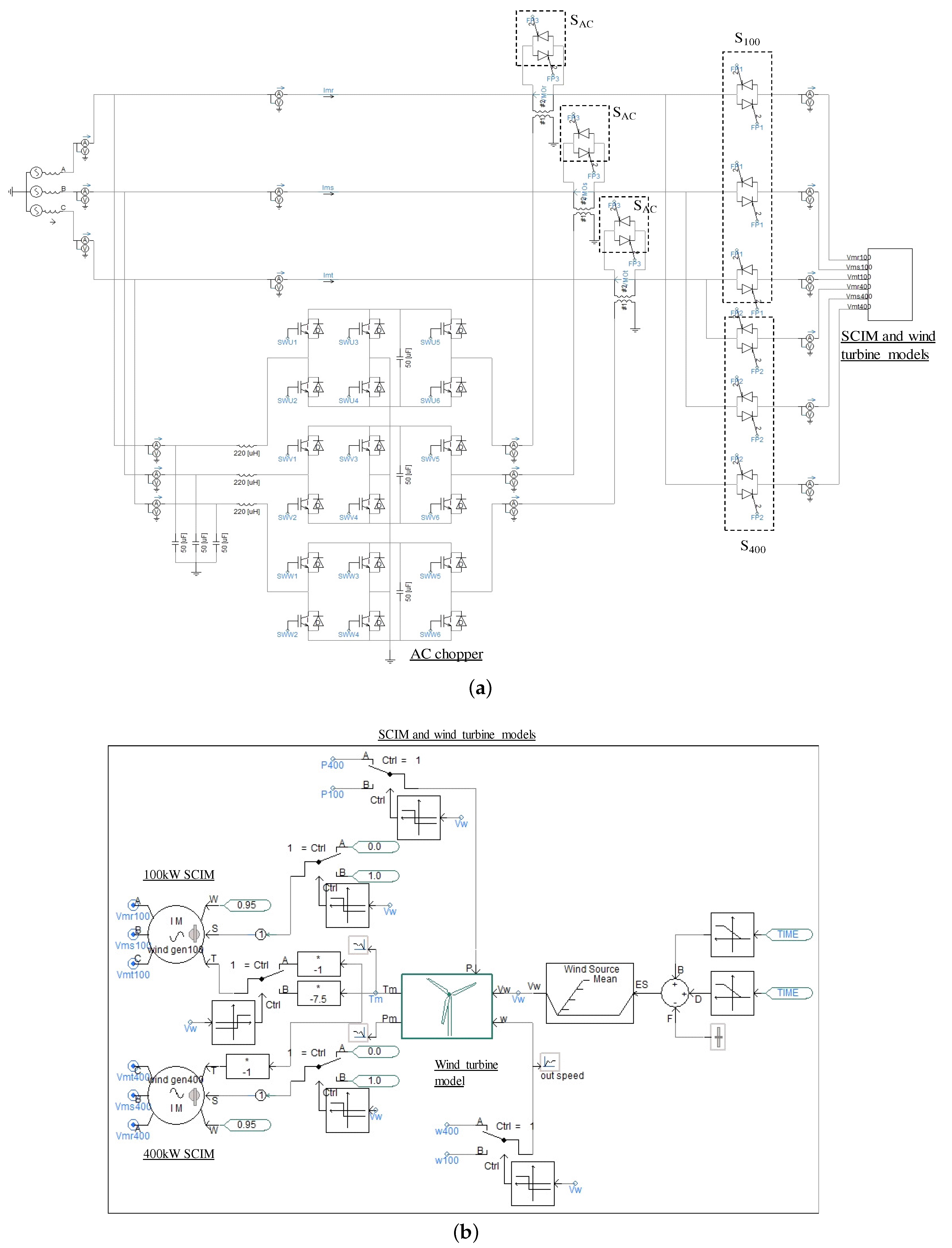
Figure 5 shows the simulation model of the proposed inrush current suppressor on the PSCAD/EMTDC. Figure 5a shows a power circuit of the proposed inrush current suppressor. , and are AC switches that consist of anti-parallel connected ideal thyristors. The SCIMs and wind turbine models are put in the subcircuit of Figure 5b. Figure 5b shows the magnified figure around SCIMs and wind turbine models in Figure 5a. The SCIM model on the PSCAD/EMTDC has speed and torque control modes. In this paper, we use the torque-control mode. The wind speed is determined by the wind-speed function block with the external speed input. The wind-speed function block is used to set the mean speed. The external speed input consists of ramp functions for the simulated wind speed variation. The mechanical torque generated by a wind turbine is provided to each SCIM.
3.1. Simulation Results of Direct Connection
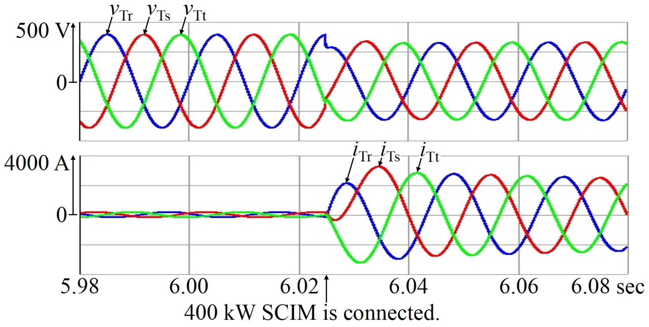
A computer simulation was implemented to confirm the inrush current and voltage sag when the SCIM was connected to the source directly. Figure 6 shows the simulated waveforms for the 100-kW SCIM. and are the r-phase, s-phase and t-phase receiving-end voltages, respectively. and are the r-phase, s-phase and t-phase source currents. When the wind speed reached 3 m/s, the 100-kW SCIM was connected. The receiving-end voltage was applied to the 100-kW SCIM directly. Thus, large inrush currents occurred. Figure 7 shows the magnified waveforms for Figure 6. From Figure 7, the maximum value of the inrush current was 1245 A. The voltage sag is approximately 11.5%. Figure 8 shows simulated waveforms for the 400-kW SCIM. When the wind speed reached over 8 m/s, the 400-kW SCIM was connected. The receiving-end voltage was applied to the 400-kW SCIM directly. Figure 9 shows the magnified waveforms for Figure 8. From Figure 9, the maximum value of the inrush current was 3253 A. The voltage sag is approximately 23.2%. Therefore, the voltage sag in all the simulation results did not meet the guideline.
3.2. Simulation Results with the Proposed Inrush Current Suppressor
A computer simulation is implemented to confirm the validity of the proposed inrush current suppressor. IGBTs are used for the switching devices in the AC chopper. Table 2 lists the circuit parameters in the simulation. The turn ratio of the matching transformers is 1:4 (AC chopper side:SCIM side). The initial value of the reference value is −0.75.
Figure 10 shows the simulation waveforms with the proposed AC chopper-based inrush current suppressor for the 100-kW SCIM. and are the r-phase, s-phase and t-phase receiving-end voltages, respectively. and are the r-phase, s-phase and t-phase source currents, respectively. and are the r-phase, s-phase and t-phase output voltages of the AC chopper. and are the r-phase, s-phase and t-phase SCIM voltages, respectively. and are the r-phase, s-phase and t-phase SCIM currents, respectively. The output voltage of the AC chopper is the same as the receiving-end voltage before connecting the 100-kW SCIM. Thus, the applied voltage of the 100-kW SCIM is almost zero when the switches S turn on. From starting the proposed inrush current suppressor, the output voltage of the AC chopper is reduced for 2 s. The applied voltage of the 100-kW SCIM is gradually increased. Thus, no inrush currents occur with the proposed inrush current suppressor. From Figure 10, the maximum source current is 25 A when the 100-kW SCIM connects to the source. At this point, the voltage sag is approximately 3.1%. From this simulation result, the inrush current of the 100-kW SCIM is reduced by approximately 98%, and the voltage sag of the 100-kW SCIM is reduced by approximately 73% by connecting the proposed inrush current suppressor.
Figure 11 shows the simulation waveforms with the proposed inrush current suppressor for the 400-kW SCIM. The output voltage of the AC chopper is the same as the receiving-end voltage before connecting the 400-kW SCIM. Thus, the applied voltage of the 400-kW SCIM is almost zero when the switches S turn on. From Figure 11, the maximum source current is 88 A. The voltage sag is approximately 7.7%. From this simulation result, the inrush current of the 400-kW SCIM is reduced by approximately 97%, and the voltage sag of the 400-kW SCIM is reduced by approximately 67% by connecting the proposed inrush current suppressor. Thus, the validity of the proposed inrush current suppressor is confirmed by the simulation results.
3.3. Comparison of the Previous and Proposed Inrush Current Suppressor
Figure 12 and Figure 13 show the simulation waveforms for 2 s when the proposed inrush current suppressor is connected to the 100-kW SCIM and 400-kW SCIM, respectively. From these simulation results, no inrush currents occur during the inrush current suppression. The capacities of the proposed AC chopper-based inrush current suppressor are calculated at the maximum point of the source current. The capacity of the proposed inrush current suppressor for the 100-kW and 400-kW SCIMs is 189.6 kVA and 416.2 kVA, respectively. Therefore, the previous inrush current suppressor is advantageous for the capacity of the inrush current suppressor, and the proposed inrush current suppressor is advantageous for the THD of the source current. Table 3 gives the comparative analysis. The previously-proposed and proposed inrush current suppressor can reduce the voltage sag to within ±10% [6]. The advantages of the proposed AC chopper-based inrush current suppressor are low inrush current and low THD as compared with the previously-proposed MC-based inrush current suppressor.
Table 4 indicates the comparison of the notch depth and area in IEEE Std 519-2014 [22]. The IEEE Std 519-2014 recommends the notch depth and area for voltage sag. The two proposed inrush current suppressors meet the IEEE Std 519-2014. The notch depth and area for the proposed AC chopper-based inrush current suppressor are smaller than those for the previously-proposed MC-based inrush current suppressor.
Table 5 indicates the energy loss of the inrush current suppressors during the inrush current suppression. In Table 5, the suppression time is 2 s for all results. To calculate the energy loss, this paper uses three parallel-connected IGBTs (Infineon, FF1400R17IP4, 1700 V, 1400 A) for each switch in the AC chopper. In the resistor connection method, the resistors used are 0.518 Ω and 0.718 Ω for the 100-kW and 400-kW SCIM, respectively. These values are approximately 40-times the stator resistance of the SCIM [13]. The energy loss of the proposed AC chopper-based inrush current suppressor can be reduced to approximately 50% as compared to the resistor connection method.
Figure 14 shows the wind speed profiles [23,24]. In this study, the cut-in wind speed used is 3 m/s. The switchover wind speed of the SCIMs is more than 8 m/s. In the case of Figure 14a, the switchover occurs once daily. In the case of Figure 14b, the cut-in is 12-times a day. It is assumed that each wind speed profile occurs at the same rate for a year. Under this assumption, the energy losses can be calculated for one year. The energy loss of the resistor connection method is approximately 306 kWh/year. However, the energy loss of the proposed inrush current suppressor is approximately 152 kWh/year.
4. Conclusions
This paper proposed the AC chopper-based inrush current suppressor in a large-capacity WPGS with two SCIMs. The switching pulses of the AC chopper are generated by the commonly-used triangular-wave comparison PWM method. Thus, the controller of the proposed method can be used in inexpensive processors. The basic principle of the proposed inrush current suppressor has been discussed in detail. The applied voltage of the SCIM can be controlled by the output voltage of the AC chopper. Thus, the proposed inrush current suppressor behaves as a soft starter without harmonic components. A computer simulation was implemented to confirm the validity of the proposed method. From the simulation results, the proposed inrush current suppressor has suppressed the inrush current to within 15% as compared to the rated currents of SCIMs. The THD was lower than the previously-proposed MC-based inrush current suppressor. The notch depth and area, which have been regulated by IEEE Std. 519-2014, were evaluated for the direct connection; in the previously-proposed and currently-proposed inrush current suppressors. The proposed inrush current suppressor can reduce the notch depth and area as compared to direct connection and the previously-proposed inrush current suppressor. Moreover, the energy loss was estimated according to two types of wind speed profiles. The energy loss was reduced to approximately 50% as compared to the resistor connection method. The authors conclude that the proposed AC chopper-based inrush current suppressor is useful for practical uses.
Author Contributions
Sho Shibata significantly contributed to the design of the proposed control strategy and contributed to the implementation of the digital computer simulation. Hiroaki Yamada proposed the basic control topology and helped with the writing of this paper. Toshihiko Tanaka and Masayuki Okamoto were responsible for guidance and key suggestions.
Conflicts of Interest
The authors declare no conflict of interest.
References
- Global Wind Energy Council. Global Wind Energy Outlook 2016. Available online: http://gwec.net/publications/global-wind-energy-outlook/global-wind-energy-outlook-2016/ (accessed on 1 November 2017).
- Kajiwara, K.; Kuboyama, S. Fujio Kurokawa Design of digital hysteresis current control circuit in AC-DC converter for wind power generation. In Proceedings of the IEEE 6th International Conference on Renewable Energy Research and Applications (ICRERA), San Diego, CA, USA, 5–8 November 2017; pp. 510–514. [Google Scholar]
- Zhang, Z.; Zhang, Y.; Lee, W. Energy storage based optimal dispatch scheme for financial improvement and fluctuation mitigation on wind power generation. In Proceedings of the 2017 IEEE Industry Applications Society Annual Meeting, Cincinnati, OH, USA, 1–5 October 2017. [Google Scholar]
- Beltran, B.; Benbouzid, M.E. Tarek Ahmad-Ali Second-Oreder Sliding Mode Control of a Doubly Fed Induction Generator Driven Wind Turbine. IEEE Trans. Energy Convers. 2012, 2, 261–269. [Google Scholar] [CrossRef] [Green Version]
- Thiringer, T.; Petru, T.; Lundberg, S. Flicker contribution from wind turbine installations. IEEE Trans. Energy Convers. 2004, 19, 157–163. [Google Scholar] [CrossRef]
- Agency for Natural Resources and Energy, Ministry of Economy, Trade and Industry. Guideline of Grid-Connection Technological Requirements for Ensuring the Power Quality. 2016. Available online: http://www.enecho.meti.go.jp/category/electricity_and_gas/electric/summary/regulations/pdf/keito_guideline.pdf (accessed on 5 January 2018).
- Medina-Domínguez, E.J.; Medina-Padrón, J.F. Critical clearing time and wind power in small isolated power systems considering inertia emulation. Energies 2015, 8, 12669–12684. [Google Scholar]
- Pires, I.A.; Machado, A.; de Braz, J.; Filho, C. Mitigation of electric arc furnace transformer inrush current using soft-starter-based controlled energization. In Proceedings of the Industry Applications Society Annual Meeting, Cincinnati, OH, USA, 1–5 October 2017. [Google Scholar]
- Shinohara, K.; Yamamoto, K.; Iimori, K.; Minari, Y.; Sakata, O.; Miyata, M. Compensating for magnetizing inrush currents in transformers using PWM inverter. IEEJ Trans. Ind. Appl. 2004, 124, 1173–1181. [Google Scholar] [CrossRef]
- Bukhari, S.S.H.; Atiq, S.; Kwon, B. An inrush current elimination technique for a voltage sag compensator while powering transformer-coupled loads. In Proceedings of the 2015 IEEE Energy Conversion Congress and Exposition (ECCE), Montreal, QC, Canada, 20–24 September 2015; pp. 2710–2714. [Google Scholar]
- Bukhari, S.S.H.; Atiq, S. Byung-li Kwon A Sag Compensator That Liminates the Possibility of Inrush Current While Powering Transformer-Coupled Loads. IEEE J. Emerg. Sel. Top. Power Electron. 2017, 5, 891–900. [Google Scholar] [CrossRef]
- Yamada, H.; Enami, M.; Hiraki, E.; Tanaka, T. A new method of compensating harmonic currents for wind power generation systems with the soft starter using a hybrid active filter. In Proceedings of the Power Conversion Conference 2007, Nagoya, Japan, 2–5 April 2007; pp. 404–409. [Google Scholar]
- Thiringer, T. Grid-friendly connecting of constant-speed wind turbines using external resistors. IEEE Trans. Energy Convers. 2002, 17, 537–542. [Google Scholar] [CrossRef]
- Yamada, H.; Hanamoto, T. A novel method of suppressing inrush currents of squirrel-cage induction machine using matrix converter in wind power generation systems. In Proceedings of the 2012 International Conference on Renewable Energy Research and Applications (ICRERA), Nagasaki, Japan, 11–14 November 2012; pp. 1–4. [Google Scholar]
- Shibata, S.; Yamada, H.; Tanaka, T.; Okamoto, M. Reduced-Capacity Inrush Current Suppressor Using a Matrix Converter in a Wind Power Generation System with Squirrel-Cage Induction Machines. Energies 2016, 9, 223. [Google Scholar] [CrossRef]
- Shibata, S.; Yamada, H.; Tanaka, T.; Okamoto, M. An Inrush Current Suppressor for Squirrel-Cage Induction Machines with Phase-Leading Capacitors Using a Matrix Converter in a Large-Capacity Wind Power Generation System. In Proceedings of the International Conference on Electrical Machines and Systems (ICEMS) 2016, Chiba, Japan, 13–16 November 2016. [Google Scholar]
- Li, Y.; Choi, N.S.; Han, B.M.; Kim, K.M.; Lee, B.; Prak, J.H. Direct duty ratio pulse width modulation method for matrix converters. Int. J. Control Autom. Syst. 2008, 6, 660–669. [Google Scholar]
- Morshed, M.J.; Fekih, A. Integral terminal sliding mode control to provide fault ride-through capability to a grid connected wind turbine driven DFIG. In Proceedings of the 2015 IEEE International Conference on Industrial Technology (ICIT), Seville, Spain, 17–19 March 2015; pp. 1059–1064. [Google Scholar]
- Morshed, M.J.; Fekih, A. A new fault ride-through control for DFIG-based wind energy systems. Electr. Power Syst. Res. 2017, 146, 258–269. [Google Scholar] [CrossRef]
- Morshed, M.J.; Fekih, A. Design of a second order sliding mode approach for DFIG-based wind energy systems. In Proceedings of the 2017 American Control Conference, Seattle, WA, USA, 24–26 May 2017; pp. 729–734. [Google Scholar]
- Okuma, Y. PWM Controlled ac Power Supply based on ac Chopper Technology and Its Applications. IEEJ Trans. Ind. Appl. 1999, 119, 412–418. [Google Scholar] [CrossRef]
- IEEE. IEEE 519-2014, Recommended Practices and Requirements for Harmonic Control in Electrical Power System; IEEE: New York, NY, USA, 2014. [Google Scholar]
- Japan Meteorological Agency. Observational Data of Wind Speed at Cape Soya. Available online: http://www.data.jma.go.jp/obd/stats/etrn/view/10min_a1.php?prec_no=11&block_no=1284&year=2018&month=1&day=1&view= (accessed on 5 January 2018).
- Japan Meteorological Agency. Observational Data of Wind Speed at Hagi City. Available online: http://www.data.jma.go.jp/obd/stats/etrn/view/10min_s1.php?prec_no=81&block_no=47754&year=2016&month=1&day=1&view= (accessed on 5 January 2018).
Figure 1.
System configuration with the proposed inrush current suppressor using the AC chopper in a large-capacity wind power generation system (WPGS).
Figure 1.
System configuration with the proposed inrush current suppressor using the AC chopper in a large-capacity wind power generation system (WPGS).

Figure 2.
Single-phase equivalent circuit of Figure 1.
Figure 2.
Single-phase equivalent circuit of Figure 1.

Figure 3.
Relationship between the effective values with the proposed AC chopper-based inrush current suppressor.
Figure 3.
Relationship between the effective values with the proposed AC chopper-based inrush current suppressor.

Figure 4.
Simulation condition by the wind speed. SCIM, squirrel-cage induction machine.

Figure 5.
Simulation model of the proposed inrush current suppressor on the power system computer-aided design/electromagnetic transients including DC (PSCAD/EMTDC). (a) Power circuit of the proposed inrush current suppressor; (b) magnified figure of SCIMs and wind turbine models in (a).
Figure 5.
Simulation model of the proposed inrush current suppressor on the power system computer-aided design/electromagnetic transients including DC (PSCAD/EMTDC). (a) Power circuit of the proposed inrush current suppressor; (b) magnified figure of SCIMs and wind turbine models in (a).

Figure 6.
Simulated waveforms of the direct connection for the 100-kW SCIM.

Figure 7.
Magnified waveforms for Figure 6.
Figure 7.
Magnified waveforms for Figure 6.

Figure 8.
Simulated waveforms of the direct connection for the 400-kW SCIM.

Figure 9.
Magnified waveforms for Figure 8.
Figure 9.
Magnified waveforms for Figure 8.

Figure 10.
Simulation waveforms with the proposed inrush current suppressor for the 100-kW SCIM.

Figure 11.
Simulation waveforms with the proposed inrush current suppressor for the 400-kW SCIM.

Figure 12.
Simulation waveforms for 2 s when the proposed inrush current suppressor is connected to the 100-kW SCIM.
Figure 12.
Simulation waveforms for 2 s when the proposed inrush current suppressor is connected to the 100-kW SCIM.

Figure 13.
Simulation waveforms for 2 s when the proposed inrush current suppressor is connected to the 400-kW SCIM.
Figure 13.
Simulation waveforms for 2 s when the proposed inrush current suppressor is connected to the 400-kW SCIM.

Figure 14.
Wind speed profiles. (a) Wind speed profile with large speed fluctuation [23]; (b) wind speed profile with small speed fluctuation [24].


Table 1.
Parameters of the squirrel-cage induction machines (SCIMs).
| Item | 100-kW SCIM | 400-kW SCIM |
|---|---|---|
| Rated power (kW) | 100 | 400 |
| Rated phase voltage (V) | 277.13 | 277.13 |
| Rated phase current (A) | 120.28 | 481.12 |
| Rated frequency (Hz) | 50 | 50 |
| Number of pole | 6 | 4 |
| Synchronous speed (rpm) | 1000 | 1500 |
| Rated wind speed (m/s) | 8 | 15 |
Table 2.
Circuit parameters.
| Item | Value |
|---|---|
| Inductor of filter (H) | 220 |
| Capacitor of filter (F) | 50 |
| Capacitor of cell (F) | 50 |
| Switching frequency (kHz) | 10 |
| Saturation voltage of IGBT (V) | 1.95 V |
| Forward voltage of diode (V) | 1.60 V |
Table 3.
Comparative analysis. THD, total harmonic distortion; MC, matrix converter.
| Item | Inrush Current (A) | Voltage Sag (%) | THD of Source Current (%) | |
|---|---|---|---|---|
| Direct connection | 100-kW SCIM | 1245 | 11.5 | 0.08 |
| 400-kW SCIM | 3253 | 23.2 | 1.1 | |
| Previously inrush current suppressor (using MC) [15] | 100-kW SCIM | 146 | 1.0 | 20.9 |
| 400-kW SCIM | 158 | 0.5 | 23.9 | |
| Proposed inrush current suppressor (using AC chopper) | 100-kW SCIM | 25 | 3.1 | 2.5 |
| 400-kW SCIM | 88 | 7.7 | 1.3 | |
Table 4.
Comparison of notch depth and area in IEEE Std 519-2014.
| Item | Notch Depth (%) | Notch Area (V s) | |
|---|---|---|---|
| IEEE 519-2014 | 20 | 22,800 | |
| Direct connection | 100-kW SCIM | 11.8 | 85,000 |
| 400-kW SCIM | 28.0 | 248,000 | |
| Previously inrush current suppressor (using MC) [15] | 100-kW SCIM | 7.4 | 19,900 |
| 400-kW SCIM | 12.1 | 21,770 | |
| Proposed inrush current suppressor (using AC chopper) | 100-kW SCIM | 3.1 | 7200 |
| 400-kW SCIM | 9.2 | 18,000 | |
Table 5.
Energy losses of the inrush current suppressors during the inrush current suppression.
| Item | Energy Loss (kJ) | |
|---|---|---|
| Resistor connection [13] | 100-kW SCIM | 212 |
| 400-kW SCIM | 486 | |
| Previously inrush current suppressor (using MC) [15] | 100-kW SCIM | 117 |
| 400-kW SCIM | 197 | |
| Proposed inrush current suppressor (using AC chopper) | 100-kW SCIM | 62.4 |
| 400-kW SCIM | 246 | |
© 2018 by the authors. Licensee MDPI, Basel, Switzerland. This article is an open access article distributed under the terms and conditions of the Creative Commons Attribution (CC BY) license (http://creativecommons.org/licenses/by/4.0/).
Share and Cite
MDPI and ACS Style
Shibata, S.; Yamada, H.; Tanaka, T.; Okamoto, M. AC-Chopper-Based Inrush Current Suppressor in a Wind Power Generation System with Squirrel-Cage Induction Machines. Energies 2018, 11, 397. https://doi.org/10.3390/en11020397
AMA Style
Shibata S, Yamada H, Tanaka T, Okamoto M. AC-Chopper-Based Inrush Current Suppressor in a Wind Power Generation System with Squirrel-Cage Induction Machines. Energies. 2018; 11(2):397. https://doi.org/10.3390/en11020397
Chicago/Turabian StyleShibata, Sho, Hiroaki Yamada, Toshihiko Tanaka, and Masayuki Okamoto. 2018. "AC-Chopper-Based Inrush Current Suppressor in a Wind Power Generation System with Squirrel-Cage Induction Machines" Energies 11, no. 2: 397. https://doi.org/10.3390/en11020397
Note that from the first issue of 2016, this journal uses article numbers instead of page numbers. See further details here.