A Control Approach and Supplementary Controllers for a Stand-Alone System with Predominance of Wind Generation


Electrical Engineering Department, Federal University of Technology, Pato Branco 85503-390, Paraná, Brazil
*
Author to whom correspondence should be addressed.
Energies 2018, 11(2), 411; https://doi.org/10.3390/en11020411
Submission received: 23 December 2017
/
Revised: 16 January 2018
/
Accepted: 30 January 2018
/
Published: 10 February 2018
(This article belongs to the Section F: Electrical Engineering)
Abstract
:This paper proposes a control approach and supplementary controllers for the operation of a hybrid stand-alone system composed of a wind generation unit and a conventional generation unit based on synchronous generator (CGU). The proposed controllers allow the islanded or isolated operation of small power systems with predominance of wind generation. As an advantage and a paradigm shift, the DC-link voltage of the wind unit is controlled by means of a conventional synchronous generator connected to the AC grid of the system. Two supplementary controllers, added to a diesel generator (DIG) and to a DC dump load (DL), are proposed to control the DC-link voltage. The wind generation unit operates in V-f control mode and the DIG operates in PQ control mode, which allows the stand-alone system to operate either in wind-diesel (WD) mode or in wind-only (WO) mode. The strong influence of the wind turbine speed variations in the DC-link voltage is mitigated by a low-pass filter added to the speed control loop of the wind turbine. The proposed control approach does not require the use battery bank and ultra-capacitor to control the DC-link voltage in wind generation units based on fully rated converter.

1. Introduction
The increasing use of distributed generation units based on traditional and renewable energy sources has contributed to the dissemination of microgrids and stand-alone power systems. A microgrid may be defined as a group of multiple distributed generation units and loads that operate as a single controllable entity, connected to the main grid or isolated from the main grid [1]. The islanded operation of microgrids and distributed generation units may bring many benefits to distribution utilities and customers, however, this operation mode requires sophisticated control approaches and special equipment to provide an effective control of the system frequency and voltage magnitude [2,3,4]. In islanded and isolated microgrids with low penetration level of wind generation, the system frequency is usually controlled by generation units based on conventional synchronous generator [5,6]. However, the increase in the penetration level of wind generation based on fully rated converter naturally reduces the system equivalent inertia, which may deteriorate the dynamic performance of the system frequency [7,8,9].
In [10], operational and control strategies are proposed for a stand-alone wind-diesel system with wind generation based on doubly-fed induction generator (DFIG), where the system frequency is controlled by the speed control loop of the DFIG. A multimode control strategy for a DFIG wind-power unit, which enables the operation in islanded mode as well as in grid-connected mode, is proposed in [11]. In [10,11], the system frequency is controlled by the speed control loop of the DFIG. In [12], the synchronous machine of a diesel unit controls the frequency of a microgrid with conventional and electronically interfaced distributed resources. Different from [10,11,12], for example, the approach herein proposed is focused on a wind generation unit with fully rated converter operating in V-f control mode.
In stand-alone systems composed only by wind generation units, the grid-side converter of the wind units usually controls the system frequency [13]. However, the stand-alone operation of wind units commonly requires the use of DC devices, such as battery bank and ultra-capacitor associated with DC-DC converter, to control the DC-link voltage [13,14,15,16]. In [17], for example, the DC-link voltage of an inverter-based distributed generation is controlled by an ultra-capacitor bank. However, nowadays, the use of battery bank and ultra-capacitor may result in additional high costs related to infrastructure and maintenance of the system.
In this context, as a novelty and a paradigm shift, this paper proposes a control strategy and a supplementary controller capable of controlling the DC-link voltage in renewable generation based on fully rated converter by means of conventional synchronous generator connected to the AC grid of the system. The analyses carried out have shown that conventional synchronous generators, which are common in most stand-alone systems and microgrids, may be controlled to provide power balance for stand-alone systems with predominance of wind generation, eliminating the need for battery bank or ultra-capacitor in the DC-link. In the herein proposed control strategy, the wind generation unit operates in V-f control mode and the diesel generator (DIG) operates in PQ control mode with a supplementary control loop that supports the stable operation of the wind generation unit. Although the evaluation of the proposed control approach has been performed taking into account a diesel generator, the proposed control strategy and controllers are general enough to be applied to other types of conventional generation units, such as generation units based on biogas, biomass, or other fossil fuels.
The proposed control allows the islanded operation or isolated operation of wind-diesel systems with predominance of wind generation. In both operating modes, wind-diesel (WD) and wind-only (WO) modes, the grid-side converter of the wind unit controls the frequency and voltage magnitude of the stand-alone system. Load variations usually lead to significant frequency variations in microgrids with synchronous generators operating in V-f control mode. In contrast, load variations result in significant variations only in the DC-link voltage in the case of microgrids where a wind unit based on fully rated converter operates in V-f control mode [14,18]. In order to overcome this problem inherent to the DC-link, supplementary control loops added to a diesel generator and to a DC dump load (DL) are proposed to regulate the DC-link voltage of the wind generation unit, allowing the proper operation of the stand-alone system with predominance of wind generation. In the wind-diesel mode, the DIG operates in PQ control mode.
The relatively high inertia moment of wind turbines is a drawback for the stand-alone operation of wind units based on fully rated converter, since the speed variations of the wind turbine strongly affect the DC-link voltage [18]. In the de-loaded operation of a wind generation unit, the changes in the wind turbine speed are frequently required in order to match the turbine mechanical power to the system load demand. The use of a low-pass filter in the speed control loop of the wind unit is also proposed to mitigate the strong effect of the wind turbine speed variations on the DC-link voltage.
The proposition of a control approach capable of controlling the DC-link voltage in renewable generation based on fully rated converter, using conventional synchronous generator, is one of the major contributions of this work. The mitigation of the strong effect of the wind turbine speed variations on the DC-link voltage is also a contribution of this work. The proposed control approach prevents the system from significant frequency variations, due to the operation of the WGU in the V-f control mode and eliminates the need for battery bank or ultra-capacitor to control the DC-link voltage in systems with predominance of renewable generation based on fully rated converter.
This paper is structured as follows. Section 2 reviews the main concepts about the stand-alone operation of wind generation units. Section 3 presents the modeling of the adopted stand-alone system. The operational and control approaches for the stand-alone operation of the hybrid system are addressed in Section 4. The obtained results and conclusions are presented in Section 5 and Section 6, respectively.
2. Wind Generation in Stand-Alone Systems
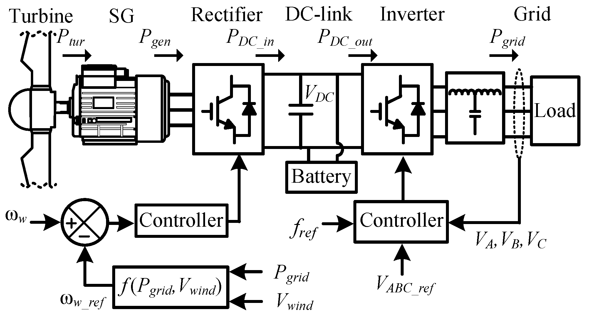
The studies carried out in this work take into account a wind unit based on electrically excited synchronous generator with fully rated converter, whose topology and typical control loops are illustrated in Figure 1. Variable speed wind turbines commonly operate in load-following mode (de-loaded operation) under stand-alone operation and in maximum power point tracking (MPPT) mode when connected to the main grid [18]. In load-following mode, the output power of the wind unit varies according to system load demand, since the grid-side converter operates in V-f mode in order to control the frequency and voltage magnitude of the system.
In the stand-alone operation of wind units, the frequency control is not a challenge, since the grid-side converter of the wind unit, which operates in V-f control mode, has a very fast dynamic response, resulting in negligible frequency deviations. In operational approaches where the wind generation operates in V-f mode, the greatest challenge is the proper control of the DC-link voltage and wind turbine speed [14,17,18]. The DC-link voltage variations are related mainly to the balance between the electric power extracted from the generator and power required by the load connected to the grid-side converter. This power balance is usually performed by battery systems and ultra-capacitor systems connected to the DC-link [13,15,17,18]. The proper control of this power balance is essential to avoid system shutdown due to the action of the protection systems during typical variations of load and wind speed. The voltage variations in the DC-link depends on the power balance described by:
where is the DC-link capacitance, is the DC-link voltage, is the input power of the DC-link, is the output power of the DC-link, is the power flow in the DC-link capacitor, is the base angular speed in rad/s. The variables and parameters with an upper bar are expressed in a per unit system (p.u.).
Accelerating Power in Wind Turbines
In load-following mode, considering the wind turbine operating in the underspeed zone [18], the wind turbine speed is usually controlled by the indirect control of the active power extracted from generator of the wind unit. The imbalance between the wind turbine mechanical power and electric power extracted from the generator results in accelerating power, which causes variation in the wind turbine speed [16]. The speed variations of the wind turbine depend on the power balance given by:
where is the inertia constant of the wind turbine and generator in p.u.s, is the wind turbine speed, is the turbine mechanical power, is the accelerating power of the rotational system. The active power extracted from the generator of the wind unit is given by , where is the electromagnetic torque of the generator, which is analogous to the torque presented in (6). Figure 2 illustrates the accelerating power and energy required to speed up a wind turbine. Due to the larger operational range, the wind turbine is operated in the underspeed zone [18].
In order to maintain the power balance in the wind unit after load variations in a stand-alone system, the control system changes the mechanical power extracted from the wind turbine. A mechanical power deviation in the wind unit requires a speed deviation in the wind turbine. Due to the relatively high inertia moment (J ) of the wind turbine, the speed deviations of the wind turbine result in large variation of the turbine kinetic energy (, where and are the initial and final speeds of the wind turbine, respectively). As illustrated in Figure 2, the wind turbine acceleration may result in high variations of the active power extracted from the generator , causing severe power imbalance in the DC-link [13,18]. The faster the turbine accelerates, the greater is the required accelerating power. In order to overcome this drawback, this work proposes the use of a low-pass filter to mitigate the strong impact of the wind turbine speed variations on the DC-link voltage.
The stable and continuous operation of the wind unit strongly depends on the capability of the controllers to ensure the power balances shown in (1) and (2). In order to ensure the power balance described in (1), this work proposes control loops added to a conventional synchronous generator and to a DC dump load in the wind unit. The suitable control of the wind turbine speed is performed by a control loop based on a low-pass filter.
3. System Modeling
This section describes the system model adopted in the assessment of the proposed control approach. Due to length limitations, the system model is concisely described. The overall topology of the stand-alone system adopted in this work is shown in Figure 3. The stand-alone system consists of a wind unit based on an electrically excited synchronous generator with a fully rated converter, an LCL filter for the grid-side converter of the wind unit, a synchronous generator driven by a diesel engine, a DL controlled by a buck converter and electric loads.
In Figure 3, u1 and u6 represent the control signals from the IEEE ST1-Type excitation system of the synchronous generators associated with the wind and diesel units; u2 and u3 are the control signals added to the generator-side converter and grid-side converter, respectively; u4 and u5 are the control signals from the proposed control loops to be presented in Section 4. The signals u4 and u5 are generated from the error of the DC-link voltage of the wind unit by the proposed controllers.
The electrical dynamics of the synchronous generator of the wind and diesel units, neglecting the effect of the damper windings, are represented by the classical third order model described by [19]:
where , , , , and are the voltages and currents of the stator and field windings, and are the resistances of the stator and field windings, is the generator speed, , and are the inductances of stator and field windings, is the mutual inductance [19]. The electromagnetic torque of the synchronous generator may be expressed as [19]:
The first order model presented in (2) describes the angular speed of the wind turbine and synchronous generator of the wind unit. The model corresponding to the mechanical dynamics of the diesel unit is given by [20]:
In (7)–(9), is the angular speed of the synchronous generator of the diesel unit, is the mechanical power supplied by the diesel engine, is active power of the synchronous generator ( where is analogous to (6), is the rotor angle of the synchronous generator, is the speed of the rotating reference frame, is the inertia constant of the diesel unit in pu.s and is the time constant of the diesel engine.
A proportional-integral (PI) controller and a proportional (P) controller are employed in the voltage regulator of the wind generator and in the reactive power regulator of the diesel unit, respectively. In both synchronous generators, the excitation system is represented by a first order model (IEEE ST1-Type excitation system).
The schematic diagram of the controllers employed in the converters of the wind unit, together with the single-line diagram of the LCL filter [21], is presented in Figure 4.
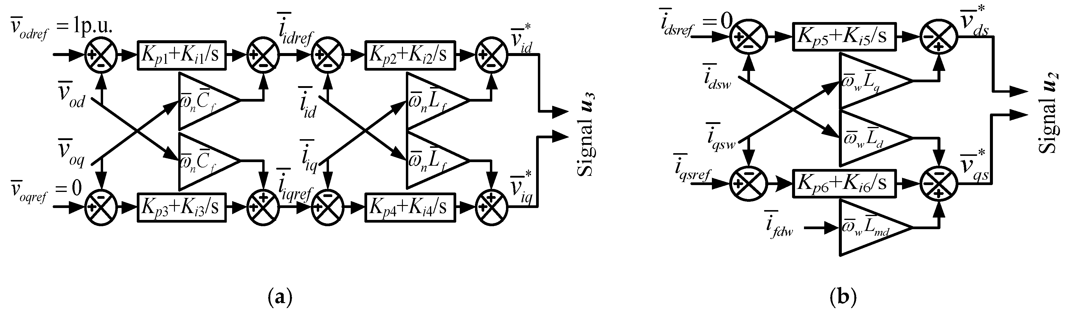
The controllers of the load-side converter and generator-side converter are standard PI controllers [21,22], whose block diagrams are shown in Figure 5.
In Figure 5, and are the current references for the current controllers; p.u. and p.u. are the voltage references at the capacitor of the LCL filter; , , and are the proportional and integral gains of the voltage controllers; , , and are the proportional and integral gains of the current controllers; , , and are the proportional and integral gains of the current controllers; , , and are the voltage references for the generator-side and grid-side converters, respectively. The variables with subscript w correspond to the variables of the wind unit generator, as described in the synchronous generator model. In the employed model, the switching dynamics of the converter switches is neglected, in this way and (signals u2 and u3 presented in Figure 3). In Figure 4 and Figure 5, is set to zero and is determined by the speed control loop of the wind unit presented in Section 4.2.
The LCL filter, inherent to the wind unit, is represented by a six-order model [21]. The buck converter of the DL, showed in Figure 3, is represented by a second-order model [23]. The system load is constant impedance type represented by a static model. The complete nonlinear model of the system is represented by 31 state variables.
4. Control Approach and Supplementary Control Loops
In stand-alone systems with small synchronous generators operating in V-f control mode, the active power variations in the system generally cause significant variations in the system frequency due to the low inertia moment of the conventional synchronous generators. These large frequency deviations may affect the power quality indices and lead to the system shutdown due to the action of the protection system. In addition, analyses of the rate of change of frequency (ROCOF) of the diesel generator and rate of change of voltage (ROCOV) of the DC-link of the wind unit have strongly indicated that the system shutdown is more likely to occur in the operational scenario corresponding to the diesel generator operating in V-f control mode. The system shutdown may occur due to large frequency deviations caused by typical and atypical load variations. These analyses are presented in Section 5. Based on the aforementioned analyses and on the fact that the generation unit with the highest nominal power is usually chosen to operate in V-f control mode [9,11], the wind unit is selected to operate in V-f control mode in the control approach proposed in this paper.
4.1. Operational and Control Approaches
The proposed operational and control approaches allow the stand-alone system to operate in wind-diesel (WD) mode and wind-only (WO) mode, without the use of battery bank or ultra-capacitor bank in the DC-link. The characteristics of each operating mode and the operational conditions which determine the transition between the operating modes are discussed in this subsection. The selection of the operating mode of the stand-alone system basically depends on four aspects: maximum power point (PMPP) of the wind turbine, loading conditions of the system (Pgrid), initialization power of the DL (PDL0) and minimum initialization power of the DL (PDL_min).
In WO mode, where the power corresponding to the maximum power point of the wind turbine (PMPP) is able to supply the system loads and the minimum initialization power of the DL (PMPP ≥ Pgrid + PDL_min), the wind unit operates below the maximum power point (MPP) and only the DL controls the DC-link voltage. In order to allow the proper compensation of the typical variations of wind speed and load, the DL may be initialized with one of the two predefined values of starting power (PDL0 or PDL_min). The choice of the DL starting power is defined according to the generation capacity of the wind unit and system loading condition. If PMPP > Pgrid + PDL0, then PDL = PDL0 and if Pgrid + PDL0 > PMPP > Pgrid + PDL_min, then the DL starting power is equal to PDL_min (PDL = PDL_min). The values for the initial power of the DL (PDL0 and PDL_min) may be chosen based on typical values of the system load variations and on the nominal power of the DL.
In cases where the wind unit is unable to supply the system loads and the DL (PMPP < Pgrid + PDL_min), the operational algorithm selects the WD operating mode, which results in the start-up and synchronization of the diesel generator. In the WD mode, the DL initial value is set to zero (PDL = 0) in order to reduce the fuel consumption in the diesel unit. In this condition, the DL is capable of mitigating only positive voltage variations in the DC-link by temporally increasing the DL power. Therefore, in WD mode, the VDC control loop added to the diesel generator is activated only if VDC < VDC_ref, otherwise it is turned off and the control loop of the DL is activated to control the DC-link voltage. Figure 6 shows the flowchart of the proposed operational approach, considering the coordination between the two proposed control loops and two operating modes. In Figure 6, the binary scalar g coordinates the activation of the proposed control loops. If g = 0, the control loop added to the DL is activated, otherwise the control loop added to the diesel generator is activated. Additional details regarding the proposed control loops are presented in Section 4.3.
In order to avoid excessive number of transitions between the two operating modes of the stand-alone system and, consequently, excessive number of start-ups of the diesel unit, a control function similar to a hysteresis function is employed in the proposed control strategy. This hysteresis function is implicitly included in the operational approach described in Figure 6 and depends mainly on the surplus generation capacity of the wind unit (Psurplus = PMPP − Pgrid) and on two predefined thresholds, PDL0 and PDLmin. The system commutates from the WO mode to the WD mode if and only if, (PMPP − Pgrid) < PDL_min and it returns to the WO mode from the WD mode if and only if, (PMPP − Pgrid) > PDL0 (i.e., if the surplus generation capacity of the wind unit is lower than PDL_min, the diesel unit is activated; If this surplus generation capacity is higher than PDL0, the diesel unit is deactivated. The difference between the thresholds PDL0 and PDL_min (∆PBacklash = PDL0 − PDL_min) results in a control action similar to a hysteresis function, where ∆PBacklash is similar to a backlash zone. The size of the backlash zone (i.e., magnitude of ∆PBacklash) may be properly determined based on typical magnitudes of load variations, nominal power of the DL and nominal power of the wind unit, since the variations in the output power of the wind unit affect the system power balance. The larger the backlash zone, the lower the number of start-ups of the diesel generator.
As previously mentioned, the transition from the WO mode to the WD mode results in the start-up and synchronization of the diesel unit. The start-up and synchronization process of small diesel units usually takes few seconds. A clutch system, inserted between the diesel engine and synchronous generator, may be employed as an alternative procedure to avoid multiple synchronizations of the synchronous generator.
4.2. Control Loop of the Wind Turbine Speed
As established in Section 2, fast variations in the wind turbine speed usually result in large deviations of the DC-link voltage [13,18], which may lead to the shutdown of the wind unit during typical variations of wind speed and load. In this context, based on a first order low-pass filter, this work proposes a simple approach to reduce the rate of change of the wind turbine speed, preventing the occurrence of large power imbalances in the DC-link. The filter is added to the speed reference signal of the speed controller of the wind turbine. The speed control loop of the wind turbine, including the low-pass filter, is shown in Figure 7, where Kpv and Kiv are the gains of the proportional-integral controller, respectively and Ta is the filter time constant.
4.3. Proposed Control Loops
The control loop added to the DL is activated in both operating modes: (1) In the WO mode, where the DC-link voltage is controlled only by DL; (2) In the WD mode, where PDL = 0 and the control loop added to the DL acts only in positive variations of the DC-link voltage. In WD mode, the control of the DC-link voltage is carried out by the DIG in cases of negative voltage deviations. The DIG is able to control the DC-link voltage by means of the active power injected into the stand-alone system. It is noteworthy that the exclusive control action of the diesel unit is capable of regulating the DC-link voltage, however, the DL is employed in the WD mode only to minimize the number of control actions of the diesel unit.
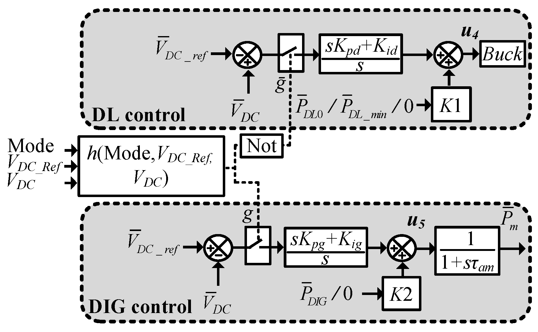
Figure 8 shows the control loops proposed to regulate the DC-link voltage and the coordination scheme which defines the coordinated action of the proposed controllers. In Figure 8, Kpd, Kid, Kpg and Kig are the gains of the PI controllers. The constants K1 and K2 are employed to set an appropriated control signal for the initial operating point of the DL and DIG (i.e., PDL0 or PDL_min and PDIG0). In the WO mode, if g = 0, the VDC control loop added to the diesel unit is kept switched off and VDC is controlled only by the DL. In the WD mode, if VDC < VDC_ref, then g = 1, which implies that VDC is controlled by the diesel unit. In this last mode, if VDC ≥ VDC_ref, then g = 0, which implies that VDC is controlled by the DL. The function h(mode, VDC_ref, VDC) illustrated in Figure 8, which determines the coordinated action of the two control loops, requires the use of a hysteresis function with a backlash zone to prevent undesirable transitions between the two proposed control loops.
4.4. Control Formulation for the Design of the Proposed Controllers
The design of the proposed controllers is carried out based on a control formulation structured in the form of linear matrix inequality (LMI) [24]. The controller design process considers two performance indices: the energy of the DC-link voltage signal and the minimum damping ratio for all poles of system linear model. A novel approach to minimize the upper limit for the energy of the output signal of the system, based on an iterative process, is proposed as an extension of the control formulations proposed in [25,26].
The design of the proposed controllers is based on the linear models of the open loop system and controllers. The state-space model employed to represent the open loop system is described by , [24]. The PI controller, in state space form, is represented in this work by with and where Kp is the proportional gain and Ki is the integral gain of the controller. The linear model of the closed loop system, composed by the models of the system and controller, is described by:
The energy of the output signal of the closed loop system, for a given initial condition , is defined as:
The energy , employed in this work as performance index, provides information about the decay of the system output. System outputs with increasing amplitude (which correspond to an unstable system) result in an increasing value of . According to (11), it is possible to conclude that well damped responses result in small values of . The controller design approach is formulated as a minimization of an upper bound for (i.e., minimization of ) [26]. The deviation of the voltage at the DC-link is employed in this work as the output signal of the closed loop system () and the input signal of the open loop system is the output of the proposed controllers added to the DIG and DL .
The minimum value for the damping ratio of the eigenvalues corresponding to the response modes of the closed-loop system, usually employed as small-signal stability margin [25], is considered as a second performance index in the controller design. Considering that , for are the eigenvalues of the state matrix which describe all the response modes of the system, the damping ratio of the i-th response mode can be defined as The damping ratio is usually specified by means of the regional pole placement in design methodologies in the form of LMIs [24,25].
The control formulation for the design of the proposed controllers, taking into account the performance indices previously discussed, is structured in the form of matrix inequalities as follows:
where Ki_min and Ki_max represent, respectively, the minimum and maximum values for the integral gains, Kp_min and Kp_max represent, respectively, the minimum and maximum values for the proportional gains. The upper bound on the maximum output energy of the closed loop system is given by and the lower bound on the damping ratio of the system eigenvalues is given by [24]. The fundamentals corresponding to the control formulation presented in (12)–(17) can be detailed found in [24,25,26].
The matrix inequalities (13) and (15), on the variables and , present nonlinear terms. This type of matrix inequality is known as bilinear matrix inequality (BMI). Control problems in the form of BMIs usually cannot be directly solved by means of conventional LMI solvers [24,25]. However, it is possible to apply a procedure that transforms the search for a solution of the BMIs into an iterative search for solutions of LMIs. A method known as V-K iterations, where V stands for the Lyapunov function and K for the controller [25], is adopted in this work to solve the BMIs. It is based on the fact that choosing a fixed value for either or transforms (13) and (15) into LMIs. Therefore, the problem can be solved by an iterative algorithm. The control problem consists in minimizing γ with respect to and subject to (12)–(17). A detailed description of the V-K algorithm can be found in [25].
As a novel approach, the upper bound for the energy of the output signal is minimized by means of a secondary iterative process. In order to minimize the energy of the output signal, the proposed algorithm reduces the initial upper bound for the energy () by means of a reduction factor in an iterative process. If the maximum number of iterations () is reached or if the V-K algorithm does not converge, the general algorithm is finalized. The controller design procedure proposed in this paper is presented in Algorithm 1.
| Algorithm 1: Procedure proposed to design the system controllers. |
| Step 1: Initialize the algorithm with , , , , , and ; Step 2: Solve the V-K algorithm (i.e., solve the matrix inequalities (12)–(17)) [25]; Step 3: Set and if , go to Step 5; Step 4: If a feasible solution was found in Step 2, return to Step 2 setting ; Otherwise, proceed to Step 5; Step 5: Set ,, and stop the algorithm. The controller gains and the minimum energy of the output signal are given by . |
The reduction factor () and the initial upper bound for the energy of the output signal may be empirically defined according to the system characteristics. However, the choice of a reduction factor too close to 1 may imply excessive number of iterations in the algorithm, resulting in an intensive computational effort required to minimize the energy of the output signal.
5. Assessment of the Proposed Control Approach
The control approach proposed for the stand-alone system with predominance of wind generation was evaluated by means of nonlinear time-domain analyses, considering the system subjected to wind speed and load variations. The system model, composed of a set of ordinary differential equations, was implemented in a programming code using Matlab® software. The solution of the nonlinear differential equations was determined using the ODE23S solver available in Matlab®. The design of the proposed controllers was accomplished by the solution of the control formulation presented in (12)–(17), using the mincx solver available in Matlab® LMI Control Toolbox. The linear model of the system, employed in the design of the proposed controllers, was generated from the nonlinear model by means of a linearization method based on the Taylor series.
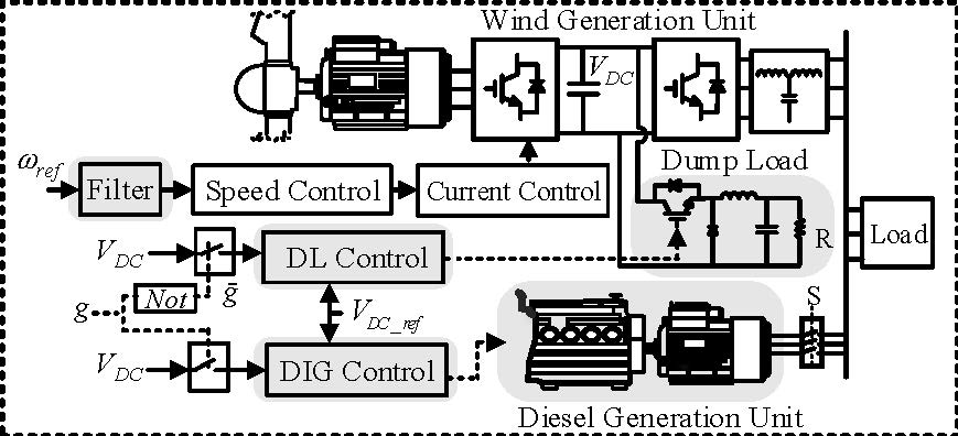
Figure 9 shows the diagrams of the stand-alone system with the proposed control loops and filter added to the speed control loop of the wind turbine. The stand-alone system considered in the evaluation of the proposed controllers is composed of a wind unit rated at 1.5 MVA, a diesel generator rated at 500 kVA and a dump load rated at 500 kVA. It is worth mentioning that the proposed control approach and control loops are general enough to be applied to systems with larger conventional generation units based on fossil fuels, biogas, or biomass, for example.
The frequency reference signal added to the grid-side converter of the wind unit is constant and equal to 60 Hz (1 p.u.) in all scenarios where the wind generation unit operates in the V-f mode. However, other frequency reference signals based on other frequency control approaches, such as droop control and virtual synchronous generator [27], may be employed in the wind generation unit without the need to modify the main control approach and controllers proposed in this work.
5.1. Impact of the Operating Mode of the System on the Frequency Deviations
The impact of the operating mode of the stand-alone system on the frequency deviations is evaluated in this subsection. The frequency of the stand-alone system operating with two different operational strategies, wind unit operating in V-f control mode and diesel unit operating in V-f control mode, is presented in Figure 10. In this analysis, the stand-alone system is subjected to a load increase equal to 100 kW at t = 1 s. It can be seen in Figure 10, in the scenario corresponding to the synchronous generator operating in V-f mode, that the load variation has resulted in a significant variation in the system frequency due to the low inertia moment of the synchronous generator, as discussed in Section 4.
An analysis of the rate of change of frequency and rate of change of voltage of the DC-link (ROCOF and ROCOV, respectively) was also performed to determine the operational approach for the stand-alone system. Table 1 shows a comparison between the initial ROCOF, given by (7) and ROCOV, given by (1), for a load variation equal to 100 kW.
Although the ROCOF is smaller than the ROCOV, the acceptable range for the frequency variations is much smaller than the acceptable range for the DC-link voltage variations. The minimum acceptable frequency for the stand-alone system, according to the considered technical standards [28,29], is 0.95 p.u. The proper operation of the grid-side converter of the wind unit requires a DC-link voltage higher than 0.49 p.u. (537.4 VDC) [18]. This analysis and the results presented in Figure 10 strongly indicate that the system shutdown, due to the action of the protection system, is less likely to occur in the scenario where the wind unit operates in V-f control mode.
It is worth mentioning that in the control approach proposed in this paper the diesel unit does not operate in the V-f mode and, consequently, there is no isochronous frequency controller in the diesel unit, since the wind unit controls the system frequency. The isochronous frequency controller was added to the diesel engine only in the assessment presented in this section in order to emphasize the large frequency deviations typical from stand-alone systems with small synchronous generators.
5.2. Assessment of the Control Approach Proposed for the Wind-Diesel Mode
The proposed supplementary control loop added to the diesel generator, in order to control the DC-link voltage in the wind unit, is assessed in this subsection. The gains designed for the supplementary controller added to the diesel unit, considering the energy minimization of the output signal, are Kpg = 1.16 and Kig = 1.36.
In this evaluation, the system loads are 1.35 MW and 0.21 MVAr, the wind unit operates with power of 1.2 MW and wind speed of 11.25 m/s. The diesel generator operates with an initial power (PDIG0) equal to 150 kW. Initially, the system is subjected to a load increase equal to 100 kW and, in the sequence, the wind unit is subjected to a wind speed decrease equal to 0.6 m/s. As aforementioned, the wind unit operates in V-f mode, controlling the frequency and voltage magnitude of the stand-alone system. The time-domain response of the DC-link voltage, wind turbine speed, active power extracted from the generator of the wind unit (GWU), mechanical power of the wind turbine and active power of diesel generator (DIG) are shown in Figure 11.
The impact of the load variation and wind turbine deceleration on the DC-link voltage is strongly mitigated by the action of the control loop added to the diesel generator. The maximum deviation of the DC-link voltage observed in the system was equal to 31 V. The load increase and the variation in the power generated by the wind unit, as shown in Figure 11b, are picked up by the diesel generator due to the action of the proposed supplementary controller. It is important to remark that the DC-link voltage would drop to zero without the action of the controller added to the diesel generator, resulting in the system shutdown.
In this scenario, the wind turbine operates at the maximum power point in order to minimize the fuel consumption of the diesel generator, therefore, the load increase at t = 1 s is picked up only by the diesel generator, maintaining the wind turbine speed constant. The decrease in the wind speed, at t = 8 s, reduces the maximum power point and the optimal speed of the wind turbine, reducing the active power supplied by the wind unit. The deceleration of the wind turbine is caused by the action of the speed controller shown in Figure 7. In this case, the deceleration of the wind turbine has resulted in a VDC drop, because the output of the low-pass filter presented in Figure 7 decreases more slowly than the decrease in the wind turbine speed.
5.3. Assessment of the Control Approach Proposed for the Wind-Only Mode
The effectiveness and performance of the control loop added to the DL in order to control the DC-link voltage are evaluated in this subsection. The impact of the low-pass filter on the wind turbine speed and on the DC-link voltage is also assessed. The filter reduces the rate of change of the wind turbine speed and, as consequence, reduces the magnitude of the DC-link voltage deviations. The gains designed for the controller added to the DL, considering the energy minimization of the output signal, are Kpd = 20.56 and Kid = 129.06.
In this operational scenario, the system loads are 1.07 MW and 0.21 MVAr, the wind unit operates with power of 1.22 MW and wind speed of 11.5 m/s. The DL operates with an initial power (PDL0) equal to 150 kW. At t = 1 s, the system is subjected to a load increase equal to 100 kW. In the sequence, at t = 26 s, the system is subjected to a wind speed increase equal to 0.5 m/s, which causes the deceleration of the wind turbine in order to maintain the generated power equal to the load demand. Figure 12a shows the nonlinear time-domain response of the DC-link voltage and wind turbine speed considering the system with and without the proposed low-pass filter. The nonlinear time-domain response of the DL power, active power extracted from the generator of the wind unit (GWU) and mechanical power of the wind turbine, considering the proposed low-pass filter, is presented in Figure 12b.
At t = 1 s, as shown in Figure 12a, the load increase and the wind turbine acceleration result in a VDC drop, due to the power imbalance in the DC-link. This power imbalance is mitigated by the control loop added to the DL. Due to the use of the low-pass filter in the speed control loop, the DL was able to significantly mitigate the power imbalance caused by the wind turbine acceleration. By neglecting the low-pass filter, as shown in Figure 12a, the high rate of change of the wind turbine speed causes a high rate of change in the DC-link voltage, making the DL unable to properly regulate VDC. In this case, due to the higher rate of change of the wind turbine speed, the DC-link voltage violates its inferior limit (VDC_min = 537.4 V), which leads to system shutdown. Comparing the two scenarios presented in Figure 12a, it possible to see that the filter included in the speed control loop of the wind turbine has a significant impact on the DC-link voltage, maintaining the system stability. It is noteworthy that the greater the filter time constant, the greater the settling time of the wind turbine speed. Therefore, there must be a compromise between the DC-link voltage dynamic performance and the performance of the wind turbine speed. A filter time constant equal to 5 s was chosen based on the mechanical time constant of wind turbine. The mechanical time constant is defined, based on the inertia constant of the wind turbine, as τmech = 2Hw, where τmech is the time required to accelerate the turbine from standstill to rated speed, taking into account the nominal torque [30].
At t = 26 s, as shown in Figure 12b, the wind speed increase results in an increase of the wind turbine mechanical power. In order to reduce the mechanical power to the previous value, the wind turbine speed is reduced, resulting in a small increase of VDC.
6. Conclusions
This paper proposed a control approach and supplementary controllers that ensure the stable and reliable operation of a stand-alone system with predominance of wind generation. In the proposed control approach, the wind generation unit of the stand-alone system operates in V-f control mode and the distributed synchronous generator operates in PQ control mode. The proposed control loop added to the distributed synchronous generator was effective in the control of the DC-link voltage of the wind unit, which eliminates the need for battery bank or ultra-capacitor. The two control loops have ensured a suitable dynamic performance for the stand-alone system subjected to wind speed and load variations. The analyses have shown that the use of a low-pass filter in the speed control loop of the wind turbine is fundamental to prevent system shutdown, due to undervoltage and overvoltage in the DC-link caused by speed changes in the wind turbine.
The typical low inertia of the distributed synchronous generator, which is a disadvantage for the operation of the diesel unit in the V-f control mode, becomes an advantage for the control of the DC-link voltage. The methodology employed in the design of the proposed controllers has shown to be suitable and effective for the considered control problem.
The extension of the proposed control approach for stand-alone systems with multiple wind generation units operating simultaneously will be one of the future directions of this research. The proposition of load shedding approaches, associated with a pitch angle control approach, so that the system can withstand larger variations in the wind speed and load, will also be addressed in future works.
Acknowledgments
The authors acknowledge FINEP, CAPES, SETI, CNPq and Fundação Araucária for scholarships and funding.
Author Contributions
Tiago Lukasievicz developed the system model employed in the validation of the proposed control approach, designed the proposed controllers, and performed the simulations and analysis of the results. Ricardo Oliveira proposed the main idea of this paper, which includes the control approach and the procedure employed to design the proposed controllers. Cesar Torrico elaborated the modeling section and contributed to the conception of the flowchart corresponding to the proposed operational approach. All authors participated in the formulation of the operational and control approaches. All authors participated in the manuscript writing process and performed a thorough revision of the manuscript.
Conflicts of Interest
The authors declare no conflict of interest.
Appendix A. Data and Parameters of the Stand-Alone System
Synchronous machine of the wind unit: Poles = 60, frate_w = 7.5 Hz, Srate_w = 1.5 MVA, Vrate_w = 960 V, Sbase = 2.0 MVA, Vbase_w = 960 V, ωb_w = 47.124 rad/s, = 0.006 p.u., = 0.00074 p.u., = 1.125 p.u., = 0.294 p.u., = 0.18 p.u., = 0.1293 p.u., , .
Wind turbine data: Vwind_rate = 12 m/s, ωturb_rate = 15 rpm, ωturb_min = 9 rpm, ωturb_max = 19 rpm, Diameter = 59.3 m, C1 = 0.73, C2 = 151, C3 = 0.58, C4 = 0.002, C5 = 2.14, C6 = 13.2, C7 = 18.4, C8 = −0.08, C9 = 0.003.
Inertia constant of the wind unit (turbine + generator): Hw = 2.33 p.u.s, Sbase = 1.5 MVA.
Diesel generation unit: Poles = 4, frate_DIG = 60 Hz, Srate_DIG = 500 kVA, Vrate_DIG = 380 V, Sbase = 2.0 MVA, Vbase_DIG = 380 V, ωb = 376.991 rad/s, HDIG = 0.125 p.u.s (HDIG = 0.5 p.u.s in the generator base power), = 0.62 p.u., = 0.11 p.u., = 10.28 p.u., = 5.08 p.u., = 1.22 p.u., = 0.9 p.u., , , τam = 0.15 s, Kei = 177.8 p.u., Tei = 0.06 s.
DC-link data: Vrate_DC = 1100 V, Sbase = 2.0 MVA, Vbase_DC = 1100 V, ωb = 376.991 rad/s, = 68.424 p.u.
Converter of the dump load: Srate_DL = 400 kVA, Vmax_RDL = 900 V, Sbase = 2.0 MVA, Vbase_DL = 1100 V, ωb = 376.991 rad/s, = 0.0014 p.u., = 0.935 p.u., = 0.502 p.u.
LCL filter: Sbase = 2.0 MVA, Vbase_f = 380 V, ωb = 376.991 rad/s, = 2.381 p.u., = 1.385 × 10⁻⁴ p.u., = 0.085 p.u., = 0.041 p.u.
Control loop gains of the excitation system of the wind generator: Kp7 = 227, Ki7 = 35.1.
Gains of the isochronous frequency controller of the diesel unit: Kp_DIG = 4, Ki_DIG = 5.
Gains of the control loops of the grid side converter: Kp1 = 14, Ki1 = 40.4, Kp2 = 56.88, Ki2 = 251.10, Kp3 = 14, Ki3 = 40.4, Kp4 = 56.88, Ki4 = 251.10.
Gains of the control loops of the generator side converter: Kp5 = 12.5, Ki5 = 100, Kp6 = 6.25, Ki6 = 100.
Gains of the proposed control loops: Kpg = 1.16, Kig = 1.36, Kpd = 20.56, Kid = 129.06.
References
- Olivares, D.E.; Mehrizi-Sani, A.; Etemadi, A.H.; Canizares, C.A.; Iravani, R.; Kazerani, M.; Hajimiragha, A.H.; Gomis-Bellmunt, O.; Saeedifard, M.; Palma-Behnke, R.; et al. Trends in Microgrid Control. IEEE Trans. Smart Grid 2014, 5, 1905–1919. [Google Scholar] [CrossRef]
- Asghar, F.; Talha, M.; Kim, S.H. Robust Frequency and Voltage Stability Control Strategy for Standalone AC/DC Hybrid Microgrid. Energies 2017, 10, 760. [Google Scholar] [CrossRef]
- Baek, J.; Choi, W.; Chae, S. Distributed Control Strategy for Autonomous Operation of Hybrid AC/DC Microgrid. Energies 2017, 10, 373. [Google Scholar] [CrossRef]
- Lim, Y.; Kim, H.-M.; Kinoshita, T. Distributed Load-Shedding System for Agent-Based Autonomous Microgrid Operations. Energies 2014, 7, 385–401. [Google Scholar] [CrossRef]
- Sebastián, R.; Alzola, R.P. Simulation of an isolated Wind Diesel System with battery energy storage. Electr. Power Syst. Res. 2011, 81, 677–686. [Google Scholar] [CrossRef]
- Qi, X.; Bai, Y. Improved Linear Active Disturbance Rejection Control for Microgrid Frequency Regulation. Energies 2017, 10, 1047. [Google Scholar] [CrossRef]
- Hossain, M.A.; Pota, H.R.; Issa, W.; Hossain, M.J. Overview of AC Microgrid Controls with Inverter-Interfaced Generations. Energies 2017, 10, 1300. [Google Scholar] [CrossRef]
- Nguyen, T.-T.; Yoo, H.-J.; Kim, H.-M. Analyzing the Impacts of System Parameters on MPC-Based Frequency Control for a Stand-Alone Microgrid. Energies 2017, 10, 417. [Google Scholar] [CrossRef]
- Sebastián, R. Reverse Power Management in a Wind Diesel System with a Battery Energy Storage. Int. J. Electr. Power Energy Syst. 2013, 44, 160–167. [Google Scholar] [CrossRef]
- Piekutowski, M.; Gamble, S.; Willems, R.; Davies, M. A Road towards Autonomous Renewable Energy Supply, RAPS Case. In Proceedings of the 44th CIGRÉ Session Technical Exhibition, Paris, France, 27–31 August 2012. [Google Scholar]
- Bhuiyan, F.A.; Yazdani, A. Multimode Control of a DFIG-Based Wind-Power Unit for Remote Applications. IEEE Trans. Power Deliv. 2009, 24, 2079–2089. [Google Scholar] [CrossRef]
- Katiraei, F.; Iravani, M.R.; Lehn, P.W. Small-signal dynamic model of a micro-grid including conventional and electronically interfaced distributed resources. IET Gener. Transm. Distrib. 2007, 1, 369–378. [Google Scholar] [CrossRef]
- Mendis, N.; Muttaqi, K.M.; Perera, S. Management of Battery-Supercapacitor Hybrid Energy Storage and Synchronous Condenser for Isolated Operation of PMSG Based Variable-Speed Wind Turbine Generating Systems. IEEE Trans. Smart Grid 2014, 5, 944–953. [Google Scholar] [CrossRef]
- Vandoorn, T.L.; Meersman, B.; Degroote, L.; Renders, B.; Vandevelde, L. A Control Strategy for Islanded Microgrids with DC-Link Voltage Control. IEEE Trans. Power Deliv. 2011, 26, 703–713. [Google Scholar] [CrossRef]
- Nguyen, T.-T.; Yoo, H.-J.; Kim, H.-M. A Flywheel Energy Storage System Based on a Doubly Fed Induction Machine and Battery for Microgrid Control. Energies 2015, 8, 5074–5089. [Google Scholar] [CrossRef]
- Hussein, M.M.; Senjyu, T.; Orabi, M.; Wahab, M.A.A.; Hamada, M.M. Control of a Stand-Alone Variable Speed Wind Energy Supply System. Appl. Sci. 2013, 3, 437–456. [Google Scholar] [CrossRef]
- Marei, M.I.; Soliman, M.H. A Coordinated Voltage and Frequency Control of Inverter Based Distributed Generation and Distributed Energy Storage System for Autonomous Microgrids. Electr. Power Compon. Syst. 2013, 41, 383–400. [Google Scholar] [CrossRef]
- Yuan, X.; Wang, F.; Boroyevich, D.; Li, Y.; Burgos, R. DC-link Voltage Control of a Full Power Converter for Wind Generator Operating in Weak-Grid Systems. IEEE Trans. Power Electron. 2009, 24, 2178–2192. [Google Scholar] [CrossRef]
- Anaya-Lara, O.; Jenkins, N.; Ekanayake, J.; Cartwright, P.; Hughes, M. Wind Energy Generation: Modelling and Control; John Wiley & Sons, Inc.: Hoboken, NJ, USA, 2009. [Google Scholar]
- Das, D.; Aditya, S.K.; Kothari, D.P. Dynamics of Diesel and Wind Turbine Generators on an Isolated Power System. Int. J. Electr. Power Energy Syst. 1999, 21, 183–189. [Google Scholar] [CrossRef]
- Pogaku, N.; Prodanovic, M.; Green, T.C. Modeling, Analysis and Testing of Autonomous Operation of an Inverter-Based Microgrid. IEEE Trans. Power Electron. 2007, 22, 613–625. [Google Scholar] [CrossRef]
- Yazdani, A.; Iravani, R. A Neutral-Point Clamped Converter System for Direct-Drive Variable-Speed Wind Power Unit. IEEE Trans. Energy Convers. 2006, 21, 596–608. [Google Scholar] [CrossRef]
- Rashid, M.H. Power Electronics Handbook: Devices, Circuits and Applications; Elsevier Science: Amsterdam, The Netherlands, 2010. [Google Scholar]
- Boyd, S.; El Ghaoui, L.; Feron, E.; Balakrishnan, V. Linear Matrix Inequalities in System and Control Theory; SIAM: Philadelphia, PA, USA, 1994; Volume 15. [Google Scholar]
- Oliveira, R.V.; Ramos, R.A.; Bretas, N.G. An Algorithm for Computerized Automatic Tuning of Power System Stabilizers. Control Eng. Pract. 2010, 18, 45–54. [Google Scholar] [CrossRef]
- Oliveira, R.V.; Ramos, R.A.; Bretas, N.G. Using the Output Energy as Performance Index in the Design of Damping Controllers for Power Systems. IET Control Theory Appl. 2007, 1, 1191–1199. [Google Scholar] [CrossRef]
- Tamrakar, U.; Shrestha, D.; Maharjan, M.; Bhattarai, B.P.; Hansen, T.M.; Tonkoski, R. Virtual Inertia: Current Trends and Future Directions. Appl. Sci. 2017, 7, 654. [Google Scholar] [CrossRef]
- 1547-2003—IEEE Standard for Interconnecting Distributed Resources with Electric Power Systems; IEEE: Piscataway, NJ, USA, 28 July 2003; pp. 1–28.
- 1547.4-2011—IEEE Guide for Design, Operation and Integration of Distributed Resource Island Systems with Electric Power Systems; IEEE: Piscataway, NJ, USA, 20 July 2011; pp. 1–54.
- Machowski, J.; Bialek, J.; Bumby, J. Power System Dynamics: Stability and Control; John Wiley & Sons, Inc.: Hoboken, NJ, USA, 2008. [Google Scholar]
Figure 1.
Autonomous wind unit operating in load-following mode with its typical control loops.

Figure 2.
Variation in the wind turbine mechanical power as function of the accelerating energy and power.
Figure 2.
Variation in the wind turbine mechanical power as function of the accelerating energy and power.

Figure 3.
Components and control signals of the stand-alone system.
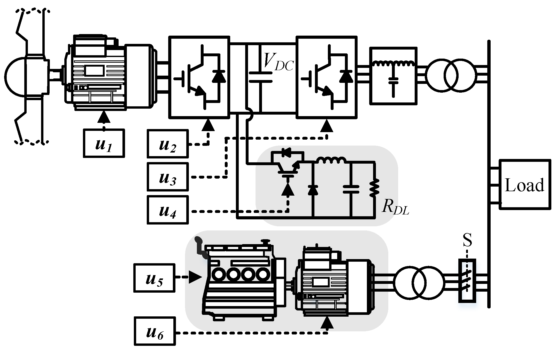
Figure 4.
Schematic diagram of the controllers of the two converters.

Figure 5.
Control loops of the converters: (a) Controllers of the load-side converter; (b) Controllers of the generator-side converter.
Figure 5.
Control loops of the converters: (a) Controllers of the load-side converter; (b) Controllers of the generator-side converter.

Figure 6.
Flowchart of the proposed operational approach.

Figure 7.
Speed controller of the wind unit with the filter proposed to reduce the rate of change of the wind turbine speed.
Figure 7.
Speed controller of the wind unit with the filter proposed to reduce the rate of change of the wind turbine speed.

Figure 8.
Diagram of the control loops added to the DIG and DL for the DC-link voltage regulation.

Figure 9.
Diagrams of the test system: (a) Single line diagram of the stand-alone system; (b) System components with the proposed control loops.
Figure 9.
Diagrams of the test system: (a) Single line diagram of the stand-alone system; (b) System components with the proposed control loops.

Figure 10.
Frequency of the stand-alone system for two different operational approaches.

Figure 11.
System dynamics for the scenario corresponding to the wind-diesel mode: (a) DC-link voltage and wind turbine speed; (b) Power in different components of the system.
Figure 11.
System dynamics for the scenario corresponding to the wind-diesel mode: (a) DC-link voltage and wind turbine speed; (b) Power in different components of the system.

Figure 12.
System dynamics for the scenario corresponding to the wind-only mode: (a) DC-link voltage and wind turbine speed; (b) Power in different components of the system.
Figure 12.
System dynamics for the scenario corresponding to the wind-only mode: (a) DC-link voltage and wind turbine speed; (b) Power in different components of the system.


Table 1.
ROCOF and ROCOV of the system.
| ROCOF (p.u./s) (Diesel Unit Operating in V-f Mode) | ROCOV (p.u./s) (Wind Unit Operating in V-f Mode) |
|---|---|
| −0.200 | −0.275 |
© 2018 by the authors. Licensee MDPI, Basel, Switzerland. This article is an open access article distributed under the terms and conditions of the Creative Commons Attribution (CC BY) license (http://creativecommons.org/licenses/by/4.0/).
Share and Cite
MDPI and ACS Style
Lukasievicz, T.; Oliveira, R.; Torrico, C. A Control Approach and Supplementary Controllers for a Stand-Alone System with Predominance of Wind Generation. Energies 2018, 11, 411. https://doi.org/10.3390/en11020411
AMA Style
Lukasievicz T, Oliveira R, Torrico C. A Control Approach and Supplementary Controllers for a Stand-Alone System with Predominance of Wind Generation. Energies. 2018; 11(2):411. https://doi.org/10.3390/en11020411
Chicago/Turabian StyleLukasievicz, Tiago, Ricardo Oliveira, and César Torrico. 2018. "A Control Approach and Supplementary Controllers for a Stand-Alone System with Predominance of Wind Generation" Energies 11, no. 2: 411. https://doi.org/10.3390/en11020411
Note that from the first issue of 2016, this journal uses article numbers instead of page numbers. See further details here.