Horizontal Axis Wind Turbine Blade Design Methodologies for Efficiency Enhancement—A Review


1
Center for Engineering Research, King Fahd University of Petroleum and Minerals, Dhahran-31261, Saudi Arabia
2
Institute for Turbulence-Noise-Vibration Interaction and Control, Shenzhen Graduate School, Harbin Institute of Technology, Shenzhen 518055, China
3
Mechanical Engineering Department, King Fahd University of Petroleum and Minerals, Dhahran-31261, Saudi Arabia
*
Author to whom correspondence should be addressed.
Energies 2018, 11(3), 506; https://doi.org/10.3390/en11030506
Submission received: 8 February 2018
/
Revised: 18 February 2018
/
Accepted: 20 February 2018
/
Published: 27 February 2018
Abstract
:Among renewable sources of energy, wind is the most widely used resource due to its commercial acceptance, low cost and ease of operation and maintenance, relatively much less time for its realization from concept till operation, creation of new jobs, and least adverse effect on the environment. The fast technological development in the wind industry and availability of multi megawatt sized horizontal axis wind turbines has further led the promotion of wind power utilization globally. It is a well-known fact that the wind speed increases with height and hence the energy output. However, one cannot go above a certain height due to structural and other issues. Hence other attempts need to be made to increase the efficiency of the wind turbines, maintaining the hub heights to acceptable and controllable limits. The efficiency of the wind turbines or the energy output can be increased by reducing the cut-in-speed and/or the rated-speed by modifying and redesigning the blades. The problem is tackled by identifying the optimization parameters such as annual energy yield, power coefficient, energy cost, blade mass, and blade design constraints such as physical, geometric, and aerodynamic. The present paper provides an overview of the commonly used models, techniques, tools and experimental approaches applied to increase the efficiency of the wind turbines. In the present review work, particular emphasis is made on approaches used to design wind turbine blades both experimental and numerical, methodologies used to study the performance of wind turbines both experimentally and analytically, active and passive techniques used to enhance the power output from wind turbines, reduction in cut-in-speed for improved wind turbine performance, and lastly the research and development work related to new and efficient materials for the wind turbines.

1. Introduction
The growing awareness of the adverse effects of the changing climatic conditions on global, regional, and local scales has led the people from all walks of life to utilize clean and renewable sources of energy to combat the increasing environmental pollution. The renewable sources of energy which are being promoted these days include the wind, solar photovoltaic, solar thermal, geothermal, big and small hydro, biomass, municipal waste, to name some. Among these energy sources, wind power has been realized as the major source of energy globally due to fast technological development and availability of all sizes of wind turbines covering almost all types of applications starting from home to grid connected large utilities. The wind power is clean, renewable, and available round the clock, though intermittently. However, it is highly fluctuating meteorological parameter and changes with location, time of the day, day of the month and month of the year, and lastly from year to year.
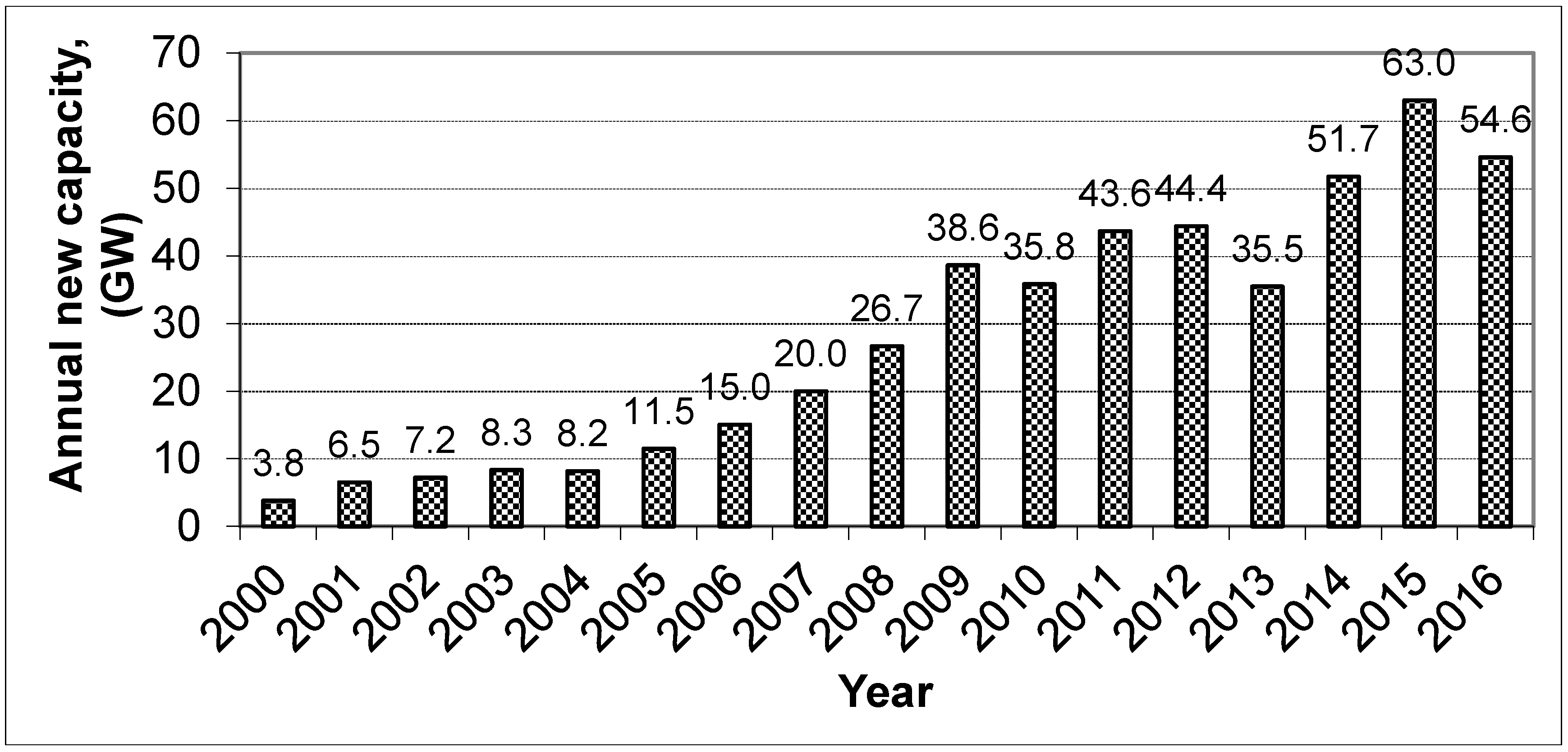
The global wind power capacities have been on the rise for almost last two decades. The continuously encouraging international trends are clear indicative of an increasing role of renewable energy sources in general, and wind power in particular meeting the current and future electricity demands [1]. The cumulative wind power installed capacity was 17 GW in 2000 and reached to 194 GW in 2010 GWEC [2], an average annual growth of around 104% over a 10-year period, as shown in Figure 1. From 2010 onwards, on an average, the global wind power installed capacity growth was 24.64%. The cumulative capacity was 238 GW in 2011 while reaching 283 GW in 2012, corresponding to an increase of 18.90%. In 2016 the global wind power installed capacity rose by 12.5% compared to 2015. The annual wind power addition on global scale is provided in Figure 2. China with 23.328 GW wind power capacity addition in 2016 remained on top of the world while USA with 8.203 GW capacity additions stood at second place. Next Germany, India, and Brazil took third, fourth, and fifth place in terms of annual wind power capacity additions of 5.443, 3.612, and 2.014 GW in 2016; respectively. It is worth mentioning that India took the fourth place whereas new wind power capacity addition is concerned in the year 2016.
A variety of wind turbines are being designed, manufactured and fabricated. The shaft orientation i.e., the rotation axis defines the first classification of the wind turbines. A turbine with a shaft mounted horizontally parallel to the ground is known as a horizontal axis wind turbine (HAWT). On the other hand, a turbine with vertical axis of rotation, the shaft being normal to the ground, is called vertical axis wind turbine (VAWT). A typical horizontal axis wind turbine consists of major parts including blades, rotor, nacelle unit, tower and gear box. The detailed description of the parts of a wind turbine is given in, Weblink2 [3]. A broad classification of wind turbines is provided in Section 2.
As a rule of thumb, the wind speed increases with height due to wind shear and decreasing effect of gravitational pull. The cost of energy extracted from the wind turbine decreases with increasing hub height and rotor diameter because of increased wind speed and rotor swept area. However, the hub height and the rotor diameter cannot be increased beyond a certain size due to structural problems, mass of the blades and nacelle unit, transportation of very large parts to the potential site, technical limitation related to the installation, and material stability constraints. On the contrary, the increasing demands of energy require efficient wind turbines, meeting the above-mentioned constraints. Hence emphasis is being given to increase the wind turbine efficiency and hence the energy yield by improving the turbine blade design and developing new, lighter and more stable materials. One of the options of improving the wind turbine efficiency is placing the micro-tabs at appropriate positions on the blade tips. Tsai et al. [4] presented an innovative design of a micro-tab system, small devices located near the trailing edge of the rotor blades, for aerodynamic load control on horizontal-axis wind-turbine rotors. These micro-tabs enable a rapid increase or decrease of the lift force through deployment of the tabs on the pressure or suction side of the airfoil, respectively. The proposed micro-tab system, due to its improved kinematics, allowed tab height to increase from 1.0 to 1.7% of the airfoil chord when fully deployed and thereby making it more effective in terms of aerodynamic load control. Fernandez-Gamiz et al. [5] optimized the size of the micro-tabs and its position on the blades to improve the aerodynamic performance of a 5 MW rated capacity wind turbine. The results showed that the implementation of micro-tabs increased the wind power output of the turbine.
Saudi Arabia has taken an initiative to develop wind farms at potential windy sites and supplement its existing power capacity by approximately 2 GW of wind power by 2032, KACARE [6]. Specifically, a capacity of 650 MW is expected to be achieved by 2020 in round 1 and another capacity addition of 1350 MW by 2032 in round 2. However, there are limited windy sites in the country for wind power realization and hence efficient turbines are being sought to extract maximum possible energy from minimum possible wind turbines.
A great effort has been put on wind turbine performance optimization. In 2006, around 100 research papers were published on this topic, around 200 alone in 2009, and more than 600 in 2013, Elsevier [7]. Keeping in view the limitations on hub-heights and at the same time increasing the energy output from the wind turbines, blade design needs to be modified in terms of decreasing the cut-in speed and/or the rated speed. Reducing the cut-in speed means that a wind turbine can start producing power at lower wind speed. On the other hand, reducing the rated wind speed means that more power can be produced at lower rated speed. This paper provides a comprehensive review of both theoretical and experimental techniques and methods used for the efficient design of horizontal-axis wind turbine blades.
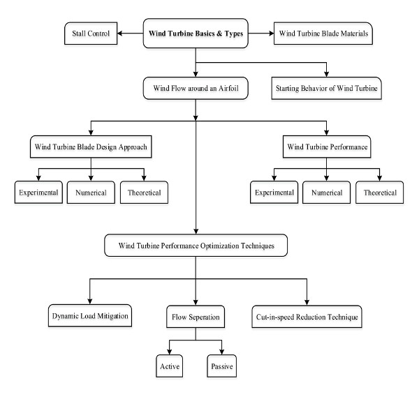
The rest of the manuscript is arranged as follows. Section 2 sheds light on the wind power related research and development conducted in Saudi Arabia. Section 3 describes broadly the wind turbine classification. The wind flow around an airfoil and its effect on its performance are discussed in Section 4 and the approaches used to design the wind turbine blades are reviewed in Section 5. Section 6 and Section 7 discuss the approaches used to study the wind turbine performance optimization. Section 8 sheds light on dynamic load mitigation on wind turbines while the flow separation techniques used for the efficiency enhancement are elaborated in Section 9. The cut-in-speed reduction techniques are discussed in details in Section 10. The stall control technique, starting behavior of turbines, and the turbine materials are briefly discussed in Section 11, Section 12 and Section 13; respectively. Finally, the concluding remarks are provided in Section 14. Complete flow information of the topics discussed in this paper is depicted in Figure 3.
2. Saudi Arabia’s Wind Power Research and Development Update
In Saudi Arabian context, a great deal of research emphasis has been made on different aspects of power related topics over last two decades. These studies include the understanding wind speed trends and inherent properties over long period using modern techniques such as wavelets and power spectrum Zheng et al. [8], Alam et al. [9], and Siddiqi et al. [10]; wind farm layout design optimization and wind turbine selection using multi-criteria algorithms Rehman et al. [11] and Rehman and Khan [12]; wind speed distribution analysis using maximum entropy principal Shoaib et al. [13] and artificial neural network for vertical estimation of wind speed Mohandes and Rehman [14] and Mohandes et al. [15]; spatial estimation of wind speed Mohandes et al. [16]; and prediction of wind speed ahead of time Mohandes and Rehman [17], Mohandes et al. [18] and Mohandes et al. [19]. The local research team has also worked on wind power resources assessment and wind characteristics for offshore locations in collaboration with Greek scientists Bagiorgas et al. [20,21,22,23] and Rehman et al. [24] and with Algerian researchers on wind power potential utilization for onshore locations Himri et al. [25,26,27]. Khan and Rehman [28] presented an overview on the effective utilization of iterative non-deterministic algorithms for optimal wind farm design and found that these methods are very useful for the above purpose.
Bassyouni et al. [29] used Weibull distribution approach to analyze the wind power potential for Jeddah, the commercial capital of Saudi Arabia. The study concluded that under the present scenario, the wind power potential can be exploited for off-grid applications for power generation. Baseer et al. [30] studied the wind power characteristics for Jubail, the industrial city of Saudi Arabia using hourly mean wind speed measured at 10, 50, and 90 meters above ground level over a period of 5 years from 2008 to 2012. The study reported that 6825 MWh of energy could be generated annually at a plant capacity factor of 25% using a wind turbine of 3 MW rated capacity. A detailed study on wind power resource assessment and design of wind farms and hybrid power system was presented by Rehman [31], as part of PhD dissertation in 2012 using wind measurements at 10 meters at 30 locations and 10, 20, 30, and 40 meters above ground level at seven stations over varying time periods. Rehman et al. [32] utilized wind speed data measured at 20, 30, and 40 m above ground level from seven stations to study the wind characteristics and wind power assessment using Weibull distribution method. The study recommended that Dhulom, Arar, Juaymah, Rawdat Ben-Habbas, and Dhahran sites as the potential locations for techno-economically feasible development for wind farms for power generation. Rehman et al. [33] conducted a detailed techno-economic analysis and provided cost of wind energy generation for 20 locations in Saudi Arabia and Rehman and Aftab [34] conducted the wind power potential assessment for coastal areas. The study calculated the wind power and plant capacity factors for wind turbines of 150 to 2500 kW rated power wind turbines and recommended Yanbo as the best location for harnessing the power of the wind and Dhahran the next best option. Proietti et al. [35] presented the assessment of different renewable sources for power generation in Nepal to (i) optimize the energy fluxes; (ii) evaluate the long-term energy balance by comparing productions and consumption; (iii) preliminary size a multiple input/output storage device on the basis of specific boundary conditions. Wind potential was estimated using CFD method and a micro wind turbine projected by the University of Perugia.
In continuation of potential site search, Rehman [36] conducted a detailed wind power analysis for Yanbo site and calculated the annual energy yield using wind turbines of 150, 250, 600, 800, 1000, 1300, 1500, 2300 and 2500 kW rated powers. The energy analysis showed higher energy yield and thus capacity factor from wind turbines of smaller rated powers compared to big ones for a 30 MW installed capacity wind farm. Rehman [37] compared energy yields from offshore site compared to the inland site in the eastern region and found higher yields from offshore site. Rehman et al. [31,38] reported the detailed wind power assessment for a remotely located site, Rafha in the eastern region for possible deployment of hybrid power systems in remotely located villages. Saudi Arabia has many villages which are not yet connected to the grid and are being supplied power through diesel generators. Hence to supplement the energy needs of these areas through wind and solar photovoltaics, techno-economic studies were conducted and possibility of renewable energy penetration was assessed. It was concluded that 25 to 35% renewable energy penetration could be achieved with the existing diesel power stations [39,40,41,42,43,44,45].
On the wind turbine selection issues, Rehman et al. [46,47] evaluated the performance of small horizontal and vertical axis wind turbines for efficient utilization for small loads in both urban and remote areas. Rehman and Sahin [48,49] compared the performance of wind power and the diesel generation for water pumping application in different regions of the Kingdom and found that wind power based system is more efficient and economical compared to the diesel power system based on international diesel process.
Baseer et al. [50] and Rehman [51] studied the performance of the wind measurement sensors using wind speed data from co-located wind speed sensors and found slight deterioration in the performance of these sensors over three to four years period. The knowledge of optimal hub height for a site is of importance from deployment logistics and energy yield point of view. In this regard, Rehman et al. [52] and Alam et al. [53] conducted a comprehensive desktop analysis using long term wind speed data from various meteorological stations and reported the optimal hub heights for future usage. The long-term wind speed trends were studied by Rehman [54] and concluded that wind speed is decreased slightly over 35 years in some regions of the Kingdom. Many other studies related to renewable energy storage options [55], grid connected wind farms of 20 MW [56] and 550 MW [57] installed capacities have been conducted to supplement the wind power development in Saudi Arabia. Furthermore, the wind speed characteristics such as wind turbulence, wind frequency distribution, wind shear exponent, diurnal and seasonal wind speed trends, energy yield, and the capacity factors have been studied in details for different regions in Saudi Arabia [58,59,60,61,62,63,64].
3. Wind Turbine Basics and Types
The device which converts the wind power into electricity is called wind turbine. This machine converts wind’s kinetic energy into mechanical energy which is then converted into electrical energy. In fact, the blades of the horizontal axis wind turbines are rotated through the wind. The conversion process uses the basic aerodynamic lift force to produce a net torque on the rotor shaft. The torque leads to a rotation of the shaft. The mechanical power produced on the shaft is finally converted into electrical energy through a generator. However, it is not possible to store wind for later use because it is intermittent in nature and highly time and site dependent, Alam et al. [65], Manwell et al. [66] and Weblink3 [67]. Wind turbines are either horizontal axis wind turbines (HAWT), or vertical axis wind turbines (VAWT). Both include some basic components: a base or foundation, tower, generator, gearbox, yaw motor, rotor, control system, and a transformer.
The wind power is clean, widely distributive, plenty, abundant, and more importantly renewable. It can be defined as the use of air-flow through wind turbines to produce power, Fthenakis and Kim [68]. A variety of wind turbines are being designed, manufactured and fabricated. The wind turbine applications extend but are not limited to charge a battery as auxiliary power in boats, to power traffic warning signals, and to contribute to domestic power supply [69]. Conventional wind turbines are classified in the following ways.
- (1)
- Based on the orientation of the rotor, these are classified as, Goldstein [70]
- (2)
- Based on the wind speed or the Reynolds number (Re) at which they operate, they are classified as [72,73]
- Low-speed wind turbine (Re < 103)
- Medium-speed wind turbine (103 < Re < 105)
- High-speed wind turbine (Re > 105)
- (3)
- Based on the positioning of turbine to flow direction, they are classified as, Kress et al. [74]
- Upwind positioned wind turbine
- Downwind positioned wind turbine
- (4)
- Based on type of aerodynamics [72]
- Drag type wind turbine
- Lift type wind turbine
- (5)
- Based on the number of blades on the rotor, Morcos [75]
- Single-bladed wind turbine
- Multi-bladed wind turbine
- (6)
- Based on the location of the wind turbine [69]
- Offshore wind turbine
- Onshore wind turbine
The lifttype HAWT’s are commonly used for harvesting the energy from the wind due to their large capacity factor [69,70]. The most critical component to harvest wind energy is the rotor which includes the blades converting wind energy to low-speed rotational energy, Malhotra et al. [76]. The generator converts this low-speed rotational energy to electrical power after converting it to high-speed rotation using a gearbox. Rotor design has been a major interest of most researchers. The shape and dimensions of the blade are determined from the knowledge of aerodynamics and the strength to resist the forces. Blade materials are selected to achieve low weight and high strength, and should be widely and easily available, Ma and Zhang [77]. The use of airfoil cross-section has been a common practice in designing the blades. Timmer and van Rooij [78] provided a comprehensive summary of the design and wind tunnel test results of the wind turbine dedicated airfoils developed by Delft University of Technology. The airfoils range in maximum relative thickness from 15 to 40% chord. The measured effect of Gurney flaps, trailing edge wedges, vortex generators and trip wires on the airfoil characteristics of various airfoils was presented. Furthermore, a relation between the thickness of the airfoil leading edge and the angle-of-attack for leading edge separation was developed. The types of airfoil used in wind turbine blade design, after Morcos [75], are:
- Flat-plate airfoil
- Symmetric airfoil
- Circular-arc airfoil
4. Description of Wind Flow around an Airfoil and its Effect on its Performance
Wind turbines usually perform poor at a low wind speed due to the laminar flow separation. The flow separation on airfoils is particularly prevalent at low Reynolds number (Re) due to the interaction of the laminar boundary layer on the suction surface with an adverse pressure gradient. The momentum contained in the boundary layer is often unable to withstand the forces imposed by the adverse pressure gradient, which causes the flow to separate near the leading edge. It is observed that the drag is reduced considerably when the flow is turbulent, White [78]. The study conducted by Moshfeghi et al. [79] showed that the streamlines of a turbulent flow over an airfoil blade separate at low velocities at the inboard section of blades.
Wind turbines are expected to generate power over a wide range of wind speed. It is clear from a typical wind turbine power curve, shown in Figure 4, that at very low wind speeds, the torque generated by the turbine blades is insufficient to rotate the rotor. As the speed increases, the wind turbine starts to rotate and generates electrical power. The minimum wind speed at which wind turbines can generate power is known as the cut-in speed and is typically between 3 and 4 m/s. As the wind speed swells above the cut-in speed, the electrical output power escalates and reaches a limit that the electrical generator is capable of. This limit to the generator output is called the rated output. The wind speed at which the generator reaches its limit is called the rated wind speed. For a wind speed higher than the rated speed, the turbine is designed to limit the power to this maximum, means no further rise in the output power. How it is done varies from design to design but typically achieved by adjusting the blade angle so as to keep the power output constant. For better performance of turbines over a wide range of wind speeds, the cut-in-speed of the wind turbines should be reduced through proper designing of blades. This paper focuses mainly on the adverse effects of flow separation and reviews studies carried out on wind turbines in order to reduce cut-in speed and avoid flow separation near the leading edge.
Generally speaking, the wind turbine blade design, prototyping, testing, and performance evaluation approaches can be classified into three groups viz., experimental, computational and analytical. The experimental approach consists of designing a prototype, testing it at various operating conditions to evaluate its performance characteristics. Alternatively, wind-tunnel testing of a blade is also performed with various measuring and flow analyzing apparatus such as particle image velocimetry (PIV), smoke flow visualization (SFV), laser sheet visualization (LSV), hotwire anemometry (HWA), etc. The computational fluid dynamics (CFD) analysis involves the use of numerical analysis and algorithm to analyze a fluid flow of a wind turbine computer model, which can be developed using ANSYS Fluent, CFX, COMSOL Multi-physics etc. In the theoretical approach, the forces acting on the wind turbine blades are determined after solving the velocity triangles forming on the blades. These forces provide the performance parameters of the turbine blades using analytical formulas. To design a wind turbine, the whole wind turbine model could be developed and the power coefficient of wind turbine can be analyzed or the blade cross-section could be designed. First, the approaches to blade design are presented followed by wind turbine study.
5. Approaches used to Design Wind Turbine Blades
5.1. Experimental Approach to Blade Design and Analysis
Lu et al. [80] studied numerically and experimentally the application of flapping-airfoil blade to the power generators focusing on the flow evolution around the airfoil which can also be employed on Wind turbines. They found that this flow evolution notably affects the aerodynamic and energy extraction performance. The NACA0012 airfoil was used to study the effect of pitching amplitude, flapping frequency, and plunging amplitude on the flow separation and output power. The study deduced that the flow separates for smaller frequencies and higher amplitudes but remains attached for certain frequency and amplitude. The latter condition complements a maximum efficiency as can be seen from Figure 5, [80]. In Figure 5, H0 is the non-dimensional plunging amplitude. Chang et al. [81] validated analytical blade design method through a series of experimental tests and compared with the standard airfoils. They found out that the designed airfoils have maximum power coefficient when designed for maximum power.
For a particular design of a turbine or blade, there is a certain range of wind speed at which the turbine produces power efficiently. At a speed lower than the range, the turbine doesn’t operate effectively. When the attack angle is about 12°, the maximum lift coefficient is reported to be about 1.3, and the minimum velocity required to generate power is estimated to be 7 m/s, Yavuz et al. [82]. The cut-in speed was found to be lower for flat-plat and symmetric airfoil blade when compared to circular-arc airfoil blade, Morcos [75]. Singh et al. [83] experimentally and numerically worked on better startup and performance of a newly designed wind turbine blade at a low wind speed. The designed blade attained the highest combinations of optimum CL and L/D ratios for low Reynolds number (<102).
To understand the effect of turbulence, Devinant et al. [84] presented airfoil test results specially for the wind turbine where the airfoil is generally used for the aeronautical applications. Lift, drag, pitching moment, pressure distributions on an airfoil blade were examined for a wind turbine under the highly turbulent flow. The results showed that turbulence level which is considered low in designing an airfoil blade for the aeronautical purposes has a significant qualitative and quantitative impact on the blade performance as depicted in Figure 6, [84]. Also, the stall behavior varied significantly from that of aeronautical applications, implying that the airfoil characteristics obtained for aeronautical purpose cannot be extrapolated for wind turbine applications [84]. It is worth understanding the applicability of the research to the commercial-scale wind turbines. To explain this further, McTavish et al. [85] experimentally conducted research on two wind turbines which were scaled down from the commercial scale wind turbines. Their results indicated that geometrically scaled rotors have degraded thrust coefficients, hence performance in a low Reynolds number environment. They recommended that experiments on the scaled wind turbine should be conducted in the range of Reynolds number for which it is designed and its testing outside the range degrades its performance.
The upper and lower surfaces of a wind turbine blade are subjected to different pressures which cause the blade to rotate, and this difference also results in the flow to mix with the main stream, producing concentrated large-scale vortical structures, called as tip-vortices. The tip-vortices contribute to the losses occurring in wind turbines. To control these losses, active and passive flow control techniques are applied to the blades. Passive flow control (PFC) techniques do not respond to flow fluctuations and changes in operating conditions, and can’t be applied to the places where a drastic change occurs in the flow. Active flow control (AFC) techniques, on the other hand, can be applied to all types of flow conditions. They are also used to control the boundary layer separation and transition characteristics Bons et al. [86] and Gul et al. [87]. Aramendia et al. [88,89] provided a comprehensive overview about available knowledge, references and investigations on the active and passive flow control devices, initially developed for aeronautic industry which are currently being investigated and used in wind turbine industry. Passive techniques allow improving the performance of the wind turbines without external energy expenditure whereas active techniques require external energy for their activation. There are many such devices and some of the most important (Vortex Generators, Microtabs, Spoilers, Fences, Serrated trailing edge) and actives devices (Trailing edge flaps, Air Jet Vortex Generators, Synthetic Jets) have been compiled in this review, Aramendia et al. [88,89].
The laminar boundary layer on S809 airfoil blade was analyzed experimentally at zero attack angle, demonstrating that the separation bubble covers 19.6% of the chord length and a flow control technique is required to reduce the losses occurring due to separation, Abdulrahim et al. [90]. An experimental study using an active flow control technique was carried out by Gharali and Johnson [91]. A three-bladed horizontal axis wind turbine rotor was tested in an open jet wind tunnel. The active flow control was obtained by injecting air through the S809 airfoil blade tips while the rotor is rotating. They showed that tip injection increased the power and thrust coefficients significantly when the tip speed ratio (TSR) was greater than 3.5. They also found out that the tip vortices near the blade were pushed out due to this injection. Another way of using AFC technique is by employing an array of synthetic jet actuators which can be mounted over the suction surface of the blade near the mid-span, as can be seen in Figure 7, which can be periodically excited, Gul et al. [87].
Sutherland et al. [92] reported on the use of two nondestructive acoustic emission and coherent optical testing techniques to monitor the behavior of wind turbine blades during a quasi-static test-to-failure. The results demonstrated the ability of the two techniques to locate and monitor both high damage regions and flaws in the blade structure. Zarouchas et al. [93] investigated, both numerically and experimentally, the prismatic composite I-beams within the up-Wind-project to examine the mechanical behavior of adhesive bond lines. The simulation results were compared with the experimental observations obtained from Digital Image Correlation Technique (DICT) and conventional techniques (Linear Variable Differential Transformers—LVDT and strain gauges). Asl et al. [94] designed and developed laminated composite I-beam reduced-scale models in three different sizes from the spar caps and the shear web geometry of a utility-scale wind turbine blade. The composite I-beams were tested in a quasi-static four-point bending configuration and strain fields of the three beams were compared and similarity of the strain distribution in the three scales was demonstrated. Asl et al. [95] proposed a novel approach to design partially similar scaled I-beams with totally different layups from full-scale I-beam. The proposed technique can predict the strain and displacement fields of the full-scale parent I-beam with very good accuracy.
5.2. Numerical Investigations of Blade Design and Analysis
Gharali and Johnson [91] studied an oscillating freestream over a stationary S809 airfoil numerically, and compared the results with the existing experimental and semi-empirical data. Since an oscillating freestream was considered over the stationary airfoil, the aerodynamic coefficient curves obtained with such flow were compared with the flow over an oscillating airfoil and all the trends were found to be almost same. They found out that trends for some of the frequencies and Reynolds number were the same as they would have been for an oscillating airfoil and stationary freestream. Lee et al. [96] numerically studied blunt trailing edge effects on a blunt tail airfoil using FLUENT at different wind speeds. The results showed that the blunt blade significantly improved the structural and aerodynamic performance of the blade at higher wind speeds. Small wind turbines operate at high tip speed ratio (TSR), so there are chances that their performances could be degraded by the compressibility of the flow. The shock-stall, where a shock wave is introduced to separate the boundary layer, may provide an over-speed protection. This phenomenon was tested computationally on a wind turbine blade and it was found that the wind speed has to be of the order of 30 m/s before the shock-stall could be applied and hence, shock stall could not be used for over-speed protection, Wood [97].
Most research in the literature has been on CFD Analysis of wind turbine blades but a few could be found where the mesh independence test is done. Almohammadi et al. [98] investigated four methods for mesh independence tests namely Mesh Refinement, General Richardson Extrapolation (GRE), Grid Convergence Index (GCI), and the fitting method for a straight blade vertical axis wind turbine. As a conclusion, it was found out that for an unsteady behavior of a wind turbine blade; the fitting method was proven to have good potential without a need of a large number of meshes. In this context, Moshfeghi et al. [79] studied the effect of grid spacing near the wall using SST-k-ω model by considering 8 different cases. They concluded that the separation point is the deciding factor for the number of nodes along the chord. To improve the performance at a low wind speed, Yavuz et al. [82] conducted a numerical study on NACA4412 blade with slat-airfoil arrangement and found out the optimum flow conditions for the wind speed of 1 m/s. The power coefficient was improved to 0.506 and reasonable agreement was reported with experimental values.
Whale et al. [99] developed a 3D Lifting-Surface Inflow Correction Method (LSIM) with the aid of a vortex-panel code in order to calculate the relationship between measured local flow angle and angle of attack. The results showed the advantages of using the 3D LSIM correction over 2D correction methods, particularly at the inboard sections of the blade where the local flow is affected by post-stall effects and the influence of the blade root. Giguère et al. [100] conducted a systematic blade design study to explore the trade-offs in using low-lift aerofoils for a 750-kW stall-regulated wind turbine. They optimized the blades for both maximum annual energy yield and minimum cost of energy taking into account aerodynamic and structural considerations. The results indicated that the effect of the maximum-lift coefficient on the cost of energy is small with a slight advantage to the highest maximum lift coefficient. Selig and Tangler [101] developed an inverse method and a computer program (PROPID) for the aerodynamic design of HAWT. The design effort was focused improving the blade performance for the Micon 108 machines. The study reported an improvement in the annual energy yield of 13–25% over the average wind speed range 4.47–8.94 m/s for the Micon 108 as compared to AeroStar 9.06 blade. Selig [102] presented a method for the design of an infinite cascade in incompressible flow. The cascade blade was divided into a desired number of segments and the velocity distribution was described over each segment with an inlet or outlet flow. Four examples were illustrated to demonstrate the capability of the proposed method. The design method is analogous to widely used multipoint inverse airfoil design described in Selig and Maughmer [103,104]. Thus, it is expected that the cascade design approach will have similar performance because it allows for multipoint design and runs rapidly on a personal computer.
5.3. Theoretical and Analytical Approaches for Blade Design and Analysis
This section presents previous analytical studies on wind turbine blade design and performance evaluation and the outcome. However, there are a number of ways like experimental, numerical, and analytical/theoretical in which blades of wind turbines can be designed and evaluated. One such method is viscous-inviscid interaction to investigate the performance of turbulent unsteady flow presented by Bermudez et al. [105]. It uses 2-D unsteady potential flow coupled with 2-D unsteady boundary layer. This method, as claimed, could be used with reasonable accuracy due to its numerical robustness and fast computational technique. Filippone [106] presented a study aimed to design two-dimensional airfoil sections for wind turbine rotors following an inverse design technique. The study aimed to design airfoils that could be specific to the application instead of the standard airfoils NACA 44xx, 63-2xx and 230-xx that are currently used in the field. The inverse design technique was followed to design the airfoils for their inboard and outboard designs. His study showed that wind turbines require section shapes quite different from standard general aviation airfoils. Cyr and Newman [107] proposed a novel method to predict the flow around two-dimensional membranes when the separation occurs at the trailing edge. The method attracts attention as it doesn’t involve empirical input, other than the shape of the airfoil under study and the angle of attack. Once the shape of the airfoil and the angle of attack are supplied, it could predict the flow over a given airfoil. The method involved iterations and was validated with the experimental measurements which provided satisfactory results.
Chang et al. [81] proposed a method which uses design objectives such as airfoil lift, drag coefficients, and lift-drag ratio; yielding an analytical expression which produces a highly smooth airfoil for wind turbine applications. The study claimed that airfoils designed by the proposed method had a delayed flow separation and high airfoil performance. The design of three-blade wind turbine rotor was presented by Johansen et al. [108] which maximizes the mechanical power coefficient (CP) at the operating conditions. The model was developed using an actuator disc and was validated using both a free-wake lifting line method and three-dimensional Navier-Stokes Solver. The study reported CP = 0.51 and pointed out that it increases and decreases towards the root and tip, respectively.
6. Approaches Used to Study the Performance of Wind Turbine
Wind turbine performance analysis is a bit complicated but critical issue and has to be dealt carefully. This section deals with this issue by reviewing the experimental studies, numerical investigations, and analytical approaches reported in the literature.
6.1. Experimental Approaches for Wind Turbine Performance Analysis
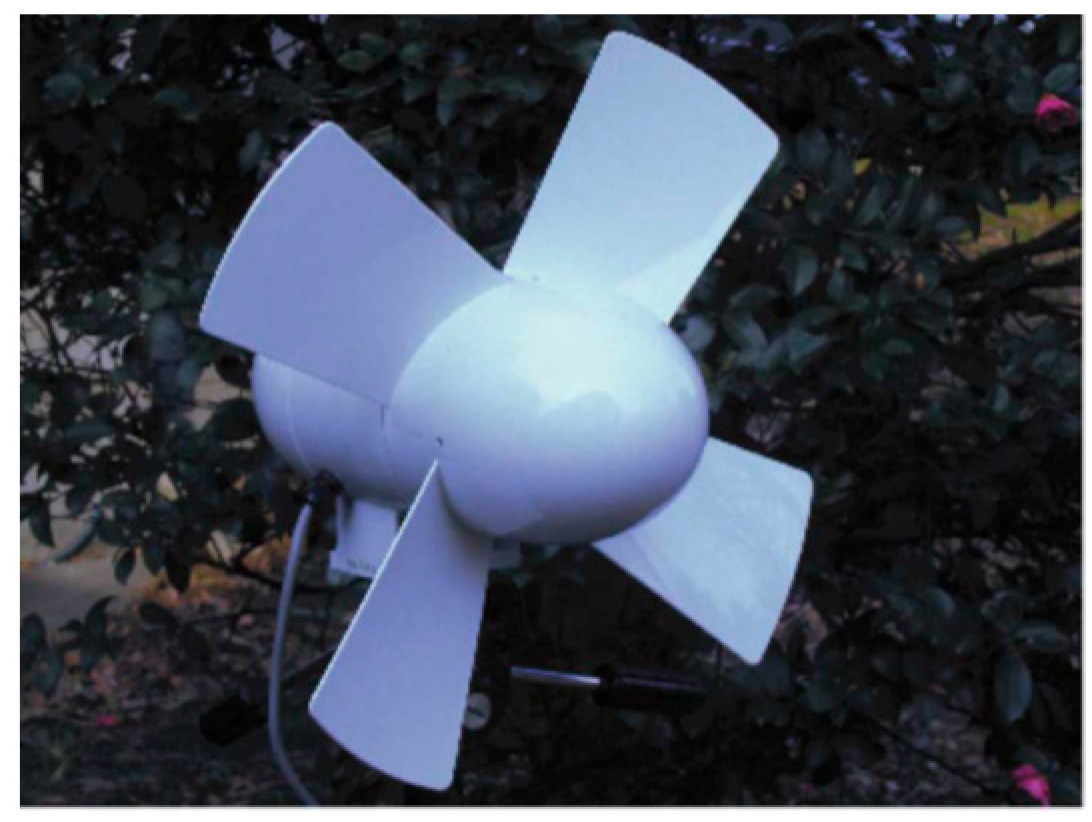
The airfoils and fans discussed above could be used for wind turbines but has to be tested and studied further before using it in a wind turbine. Some studies on the airfoil blades used in wind turbines have been found in the literature. In this context, Rocha et al. [109] designed a blade with cambered and symmetrical airfoils, NACA0012 and NACA4412 respectively, and used it in small scale wind turbine and concluded that the cambered airfoils had the higher power coefficient than the symmetrical airfoils and hence, should produce more power for the same wind speed. A wind-tunnel study of a horizontal axis wind turbine was carried out by Grant et al. [110] to observe the behaviour of the vorticity trailing from the turbine blade tips. The LSV technique was used to trace the wake which highlighted key features of the wind-turbine wakes and its interaction with wind tunnel wall. An experimentally studied small wind turbine results have been reported by Hirahara et al. [111]. Energy output, power coefficient and torque of turbine were obtained for a range of wind speeds. The flow around the blades was visualized by PIV (Particle Image Velocimetry). The maximum power coefficient for their turbine obtained is 0.4 which is good enough for a small-scale turbine. The image of this small four-bladed wind turbine is shown in Figure 8. The International Electrotechnical Commission (IEC) Standard for small wind turbine safety, IEC 61400-2, defines a small wind turbine as having a rotor swept area of less than 200 m2 which corresponds to a rated power of about 50 kW. Until the beginning of the twentieth century, all wind turbines were small, at least in terms of power output, and were used for water pumping and milling rather than producing electricity, Wood [112]. This book demonstrates that, a century later, small wind turbines can be designed and built to avoid many of the problems that faced Grim-wade.
When a cylinder spins, the Magnus effect comes into being and generates a force at an angle to the axis of spin of the cylinder, as shown in Figure 9. In Figure 9, a and á are the axis and angular induction factors, Uw and U∞ are the treadmill speed and free stream velocity, FL and FD are the lift and drag forces, ϕ and ϖ are the relative wind angle and spinning speed of cylinder, and rc are the rotor angular speed and radial coordinates. This concept is applied to increase the lift to drag ratio in a wind turbine. Sedaghat et al. [113] used the Magnus effect to increase the lift to drag ratio and obtained a high lift to drag ratio for a wind turbine blade. The Magnus effect is produced by rotating any symmetrical shapes (symmetrical airfoil NACA 0015 in his case) and computationally tested it as wind turbine blade. A very high lift to drag ratio of 278 was obtained exploiting this effect, compared with 200 which is a maximum possible reported in the literature. Wind turbines are not always operated at steady loads hence the output power fluctuates considerably. In this context, Kress et al. [74] assessed a downwind turbine experimentally by tilting and coning the rotor to minimize the load fluctuations and found out that tilting and coning have an opposite effect on downwind turbine when compared to a upwind turbine. The tilting decreases the fluctuations while coning increases the fluctuations on the downwind turbine. They concluded that large tilt angles and moderate cone angles should be preferred for downwind turbines.
6.2. Numerical Investigations for Wind Turbine Performance Analysis
Bottasso et al. [114] implemented a device as a flap or pitching blade tip which responded in the reduction of blade vibrations and the fluctuation of load on wind turbine. The proposed wind turbine was numerically investigated and the results showed that the fatigue damage to the structure was considerably reduced without any effects on ultimate loads and power production. Han et al. [115] proposed a wind turbine which could effectively utilize low grade wind energy by using the effect of shroud and lobed ejector. The results showed that for a low wind speed range of 2 to 6 m/s, the wind energy utilization efficiency of the turbine increased by 70% and the power output by 240% as can be seen from Figure 10. In Figure 10, Cp is the wind energy utilization efficiency. Winglets (shown in Figure 11) are vertical projections on an airfoil blade which help reduce the drag and increase L/D ratio. Elfarra et al. [116] designed a winglet on National Renewable Energy Laboratory (NREL) rotor blade and optimized for the computational cost using the artificial neural network at different wind speeds. The study reported around 9% increase in the power for the horizontal axis wind turbine. To study this effect, a free stream turbulence was considered with a large integral scale on an airfoil-blade (S-809) by Maldonado et al. [117]. Their results concluded that very large scale eddies significantly improved the aerodynamic performance, i.e., L/D ratio increased for all the attack angles except 0°.
The aerodynamic data of HAWT 3D CFD model (shown in Figure 12) were developed using ANSYS solver by Lanzafame et al. [118]. Instead of using fully turbulent flow, the empirical correlations of transitional turbulence model was considered which is less cumbersome. The results were validated with the experimental data of NREL PHASE VI rotor available and comparison showed that this model produced highly reliable results. A numerical study on NREL PHASE VI blade on a Horizontal axis wind turbine was conducted for the separation and stall behavior of the turbine while in rotation. Drag and lift coefficients were extracted from the numerical model which could help in developing a stall model for a wind turbine and predicting the critical angle of attacks, Yu et al. [119].
The built-up areas when compared to wind farms have large obstructions in the form of buildings where turbulence in the flow is created at low wind speeds in addition to the local vortices due to flow obstruction. Wang et al. [120] proposed a scoop design for the blade for domestic purpose wind turbines. Scoop was able to increase the energy capture at low wind speeds. It was found that the scoop boosts the airflow by a factor of 1.5 with and equivalent increase in the power output by a factor of 2.2 which can be observed from Figure 13. The domestic wind turbine with scoop was further tested by Wang et al. [121]. The scoop altered the radial velocity directions and enhanced the airflow at the tips. To obtain the highest power, the volume of the scoop should be kept as minimum as possible, and the location should be at the inlet. The power curve and the annual power output were predicted numerically for such a turbine. Water pumping is one of the oldest applications of wind power, and the device used is known as a windmill. Windmill blades (Figure 14) can also be used in wind turbines which have very high solidity, are thin and run at slow speed. In this context, Fagbenro et al. [122] investigated numerically the aerodynamics of windmill blades used in wind turbine and found that increasing the solidity caused the lift and drag to depart substantially.
Computational fluid dynamics has been used widely to study the behaviour of wind turbine performance. Limited work has been found in the literature related to the effect of aerodynamic load on the motion responses of the wind turbines. The importance of motion response may be realized in modeling of shafts, bearings, gearbox and generators apart from wind turbine. One such approach comprised of CFD was used to study the effect of aerodynamic load on motion response for multi-body dynamics. Such an approach showed a good agreement with the available simulation results and depicted increased wake diffusion. The methodology plays an important role when a wind turbine operates under complex operational environments, Li et al. [123]. There are some studies carried out on flow fans in the literature. Li et al. [124] studied the effect of abnormal blade angles on axial flow fan for its aeroacoustics and energy performances. The numerical results showed that at abnormal blade conditions, the noise becomes high and fan performance reduces.
6.3. Analytical Approaches for Wind Turbine Performance Analysis
The wind turbines even though have been receiving a large number of investments are still not popular in general public mostly due to the marketing policies of manufacturers. The realistic energy output that could be received from a wind turbine is not known to the general public. To educate the general public, Bukala et al. [125] carried out sensitivity analysis theoretically to determine the important parameters influencing the efficiency and power of a small-scale wind turbine. The weather predictions were used to educate the people about the power magnitude that could be produced each month with the given design. A parametric study on multi-bladed horizontal axis wind turbine was carried out theoretically using three different blade sections namely, flat-plate, symmetric and circular-arc. The effect on power thrust and torque was investigated by varying tip speed ratio, blade angle, rotor solidity, drag/lift coefficient ratio and blade section and the optimum conditions were pin pointed by Moshfeghi et al. [79]. A wider range of tip speed was predicted for flat-plate and symmetric airfoil blades in the study. The increase of tip-speed ratio and solidity and decrease of CD/CL ratio showed an increase in the power coefficient [79].
Many new designs of wind turbines can be found in the literature with a view to increasing the power coefficient and aerodynamic efficiency, and reducing manufacturing cost. Goldstein [70] proposed and analyzed a tilted-axis wind turbine with a downwind rotor. He argued that the proposed system could be 2.5 times less expensive than conventional wind turbine for the same power at a given location and could be 80% lighter as compared to horizontal axis wind turbines. For offshore located wind turbines, instability becomes a dominant problem, known as coupled-mode flutter instability. The wind flow velocity at offshores keeps on changing and in some cases reverses. This type of aerodynamic loading, when applied on flexible blades, causes flutter, referred to as couple-mode flutter instability. Pourazarm et al. [126] made a parametric analysis of a 3-MW-size wind turbine blades to study the effect of a change in velocity and structural modes on coupled-mode flutter phenomenon. The influence of torsional and flapwise natural frequencies was observed using a three-dimensional blade model. They reported that all the blades have a uniform behaviour and concluded that the most influential parameters are the first torsional natural frequency and the ratio of first torsional natural frequency to the first flapwise natural frequency. The speed at which flutter occurs is called critical flutter speed. It can be even lower than the blade rated speed with low torsional frequencies.
Recall Figure 4 where cut-in, rated and cut-out speeds are marked. Above the rated speed, the wind turbine needs to be designed for structural integrity by controlling the angular speed and the couple generated. Below the rated speed, the coupled and angular speeds need to be controlled to maximize the power generated from the turbine. Both the design criteria have been studied in the literature but separately. Capuzzi et al. [127,128] combined these objectives and developed a new aero-elastic approach to aerodynamically design the turbine. In part I, the optimum total twist that maximizes the power at different wind speeds was obtained. In part II, the structural point of view of the optimum twist was analyzed followed by an assessment of the increase in the annual power harvested using the desired approach. A significant increase in annual energy production using this approach was obtained. Wang et al. [129] presented a comprehensive review of the aero-elastic modelling of wind turbine blades, available models for aerodynamic, structural, and cross-sectional analysis, advantages and disadvantages of the available models, and finally outlines the current implementations in this field.
6.3.1. Blade Element Momentum Theory
The Blade-Element-Momentum (BEM) theory is the basis of many aerodynamic models due to its relatively high computational efficiency compared to free-wake vortex methods and CFD. Blade element momentum theory uses the airfoil characteristics data to predict the aerodynamic performance of a wind turbine. The reliability of this theory depends on the accuracy of the results obtained from the CFD analysis of the airfoil. One of the main advantages of Blade-Element-Momentum (BEM) is that it requires very less computational time. The airfoil studies carried out are under static conditions and when the airfoil is used for the wind turbine purposes, aerodynamic corrections should be made, Manwell et al. [66]. BEM theory coupled with structural dynamics of the blade is also found to be in use in the literature which can predict the overall cost of energy from a wind turbine, Buck and Garvey [130]. In this context, Yang et al. [131] extracted the airfoil data using CFD. The azimuthally averaged velocity was used instead of the local velocity for defining the attack angle, and lift and drag coefficients were determined using the forces on the airfoil while extracting airfoil data. These extracted data were inputted into a BEM code without any further corrections, and results then showed a good agreement with the experiments. An improved BEM theory was proposed by Sun et al. [132] to overcome the drawbacks of classical BEM theory. The pressure drop due to wake rotation and the effect of radial velocity at the rotor disc were included in the modified BEM theory. The numerical tests showed that improved BEM gives better prediction than the classical BEM, especially in the blade tip region. Hence, the improved BEM theory is recommended for predicting the wind turbine performance from the aerodynamic airfoil data. Sant [133] conducted a detailed investigation of the aerodynamics of wind turbines with an objective of providing a better understanding of the limitations of the BEM theory. The study identified the importance to pursue turbine aerodynamics and modelling with an integrated approach and developed new analytical methodologies which compensate for the limitations in experimental data. Finally, Sant [133] provided guidelines for developing improved models for BEM-based aerodynamics codes for wind turbines.
A number of models exist for the momentum theory, with each one having its own limitations and applications. Another similar approach by Ricardo proposed modifications by adding a source at the actuator disc to include the effects of divergent stream tube. The intensity and location of this source would be dictated by the geometry of stream tube. The results achieved using this modification were claimed to be closer to the experimental values, Prado [134].
An important theory for diffuser-augmented wind turbine (DAWT), known as Generalized Actuator Disc Theory (GADT), was first proposed by Jamieson [135] and it was later further extended by Liu and Yoshida [136]. This theory can accurately predict the turbine performance Jamieson [135] and the distribution of axial velocity profile and velocity speed-up ratio at the rotor plane for various conditions Liu and Yoshida [136] with only limited knowledge of CFD/Experiment information of two loading conditions. Ohya et al. [137] developed a wind turbine consisting of a diffuser shroud with a broad-ring flange at the exit periphery and a wind turbine inside it. The flanged-diffuser shroud plays a role as a device for collecting and accelerating the approaching wind. The flange generates a low-pressure region at the exit of the diffuser by vortex formation and draws more mass flow inside the diffuser shroud. The results showed that a shrouded wind turbine equipped with a flanged diffuser produced more power for a given turbine diameter and wind speed by a factor of about 4–5 compared to a standard (bare) wind turbine. Abe et al. [138] investigated flow fields around a small wind turbine having a flanged diffuser both experimental and numerically. The proposed wind-turbine model gave a power coefficient higher than the Betz limit (¼ 16 = 27) due to the effect of the flanged diffuser. The experimental and numerical results showed a considerable difference in the destruction process of the tip vortex between the bare wind turbine and the wind turbine with a flanged diffuser.
6.3.2. Other Proposed Theories
A quick method for predicting the aerodynamic load on a wind turbine is proposed by Wang et al. [62]. Their method uses 3D panel method coupled with Reduced Order Model (ROM) (PANROM). 3D panel method is a kind of BEM which analyzes the flow field and the aerodynamic data are used in ROM generated by proper orthogonal decomposition (POD). The results adhered to experimental results were quite enduring, forming an essential tool in performing wind turbine calculations, Wang et al. [139]. An experimental analysis was conducted by Ahmed and Archer [140] on the horizontal axis wind turbine to validate the Sanderson’s theory, Sanderson and Archer [141], which is a method to predict the optimum performance and corresponding geometry of HAWT with the help of design curves. The experimental analysis carried out based on this theory offered a rational basis for the design of propeller wind turbines at high loads and is found to be fairly simple, only needing a hand-held calculator for design calculations at peak performances.
7. Wind Turbine’s Performance Optimization Techniques
The output power of any power producing device is maximum when it is operated at the optimum conditions. Similar is the case for wind turbines. They produce maximum power if the rotors are driven at the optimum rotational speed for a particular wind speed. In order to obtain that a maximum power point tracking (MPPT) controller is used taking instantaneous measurements of wind and rotor speeds, and from the rotor-generator characteristics, the rotational speed could be controlled. A universal MPPT controlled without rotor-generator characteristics of achieving this is proposed by Narayana et al. [142]. An adaptive filter is used which senses the aerodynamic power. This signal is then used in conjunction with the hill-climbing control method to control the rotational speed. The results showed an improvement in the performance. In addition to wind speed, there also exists an optimum angle of attack that can produce a maximum power at a given wind speed and given blade geometry. The same data for an untwisted blade could be obtained from the research carried out by Thumthae and Chitsomboon [143]. It is found that the wind speed and optimum angle attack share a direct proportionality, and the study has also shown the importance of optimum angle of attack to the design of wind turbine. A theoretical optimization technique to develop an efficient wind turbine for a particular area in Iceland has been developed by Perkin et al. [144]. A turbine may be called efficient if it has high performance and less cost of energy. For this reason, BEM combined with a realistic cost model was developed to optimize the wind turbine design.
Due to a large number of wind turbines located offshore, a coupled-mode flutter instability, the aero elastic instability in flexible blades of a wind turbine subjected to aerodynamic loading when the flow velocity changes or the structural mode coalesce, is a predominant problem. Pandey et al. [145] presented an analytical approach for optimum performance for HAWTs which included the effect of drag and number of blades and is simpler than the earlier approaches. The results were then compared and were found in good agreement.
Every shape of the wind turbine blade gives its best performance at a specific range of velocities and the location it is designed for. Choosing a wind turbine blade for a given location can be obtained from Vu et al. [146]. A computational model based on the given wind speed has been developed, rendering a custom-shaped blade for the given conditions corresponding to an optimum performance, maximum annual energy production, net present value and internal rate of return depending on objective function. They concluded, that further work would be required because power coefficients predicted by this algorithm were high compared to experimental values. In order to maximize power coefficient and minimize the chord length, the airfoil design was proposed by Zhu et al. [147]. Using the integrated method of airfoil and blade design, the airfoils can be designed for high power performance and low cost for a given rotor diameter and tip speed ratio. Once, the airfoil design is selected, it is optimized based on the local speed ratio. Results showed that the method has the potential of being a reliable tool for airfoil and rotor platform designs.
Each of the above-stated optimization techniques and methods focuses on a single objective while designing the airfoil blades and turbines. A need of multi-objective optimization to find the best trade-off between all the different objectives is evident, such as, maximizing annual energy production; minimizing blade loads, cost, and root moment. Sessarego et al. [148] applied a concurrent-hybrid non-dominated sorting genetic algorithm to the optimization of the annual energy production, flapwise root-bending moment and mass of the NREL 5 MW wind-turbine blade. From this study, a three-dimensional surface representing the optimal trade-off between the annual energy production, flapwise root-bending moment and blade mass was achieved. However, the addition of local gradients in the blade optimization, showed no improvement in the convergence for three-objective problem. Wang et al. [149] used a novel gradient-based multi-objective evolution algorithm based on both uniform decomposition and differential evolution for the design of wind turbine blades, to overcome unsatisfactory convergence performance and diversity of solutions usually existing in conventional evolution algorithms. Two-objective, three-objective, and four-objective optimizations for the 1.5 MW wind turbine blade designs revealed that the proposed algorithm exhibits improved distribution, convergence, and converging efficiency compared to the conventional evolution algorithms.
In an earlier study, Wang et al. [150] applied a novel multi-objective optimization algorithm on a 5 MW wind turbine blade design by considering the maximum power coefficient and the minimum blade mass as the optimization objectives. The results showed good performance of the proposed method in handling the multi-objective optimization of wind turbines and it provided a Pareto-optimal solution set rather than the optimum solutions to the conventional multiobjective optimization problem. Shen et al. [151] presented such optimization method based on lifting surface method to obtain the best trade-off between the objective functions. More efficient designs could be obtained by combining all the objectives to a single objective by using this method which can maximize the power output without the thrust on the rotor going out of control.
8. Dynamic Load Mitigation on Wind Turbines
Wind turbines are not always operated with steady loads; hence the output power fluctuates considerably. Due to the influence of shear, turbulence, and wake, the safety and reliability of a wind turbine is at risk. Most of the fatigue damage is found to have occurred when the turbine rotates beyond rated speed, Zhang et al. [152]. For this reason, wind speed regions contributing little to fatigue damage are identified prior to optimization of the turbine, Smit et al. [153]. Deflecting the trailing edge is adapted to increase the maximum power. In these low fatigue damage regions, using BEM the size of deflection is determined. It was found that at optimum tip speed ratios, deflecting the trailing edge doesn’t increase the power coefficient. It is only helpful at suboptimal tip speed ratios.
The current trend of using large rotor diameters to reduce the cost of producing power also increases the size of wind turbine structure. Higher the spatial dimensions, more complicated the turbulence along the blades. In this regard, a smart blade is proposed, equipped with a number of control devices that senses the strains and provides the feedback using the pitch system. When known, the disturbances could be perfectly canceled out using this smart blade configuration. The case studies carried out experimentally using this blade, showed that the disturbances can be reduced upto 90%, Wingerden et al. [154]. Many other blade control strategies exist in the literature; sensing flapwise acceleration, root moment, and tip deflection on the blade could also be used to enhance the damping of the fluid-structure system which facilitates to reduce the loads on blade, drive-chain components and tower. The flapwise root moment was found to outperform the other two strategies, Zhang et al. [152]. An attempt is made to reduce the fatigue load on the wind turbine rotor by introducing the concept of smart rotor. A smart rotor can sense the strain and acceleration which can then be used to control the loading in spanwise direction. The fatigue load reduction potential of a smart rotor was explored by Hulskamp et al. [155] experimentally by scaling down the rotor. The results showed that a significant dynamic load and fatigue losses could be reduced if the coupling between the different blades has been taken care of by the controller. If the rotor has to be scaled up, further considerations need to be addressed such as, design of large-scale flaps, the reliability and stability of the rotor.
9. Flow Separation Techniques for Wind Turbine’s Efficiency Enhancement
A boundary layer is developed when air flows over wind turbine blade. This layer is close to the surface where viscous forces are dominant. This boundary layer grows as the air continues to move over the blade surface. The fluid in the innermost part of the boundary layer is slower than that of the outer layers, Schlichting and Gersten [156]. The increasing fluid pressure in the direction of the flow causes the kinetic energy to decrease, hence the velocity reduces in the boundary layer. When the pressure is increased, the velocity of the boundary layer relative to the surface becomes zero and the flow is separated. The velocity behind the separation is reversed. Here we mainly focus on the adverse effects of flow separation and a review of studies is carried out on reducing cut-in speed and avoiding flow separation near the leading edge.
Extensive research has been carried out and is still ongoing to delay this flow separation or to keep the flow attached to the surface as long as possible. The techniques manipulate the boundary layer either to increase the lift or decrease the drag. When a technique doesn’t require any power to achieve the desired target, it is known as a passive flow control technique. This type of technique is cheaper and simple and doesn’t contribute to additional costs. The active flow control techniques require some amount of power to manipulate the flow, such as the power to run vortex generators, steady suction or blowing, etc, Yousefi and Saleh [157]. Such techniques tend to increase efficiency for the part and over-load operations but maintenance and upfront costs increase making it economically feasible for large scale applications, MacPhee and Beyene [158].
9.1. Active Flow Control Techniques
An active flow control technique was applied to an automotive vehicle to reduce the drag by injecting steady jets in the normal and tangential directions to avoid the separation. Nearly 3% reduction in power consumption was attained by this injection by modifying the flow. This study showed the need of a flow control technique on a wind turbine blade where power is produced at higher levels, and a 3% increase could be of substantial advantage, McNally et al. [159].
The dielectric barrier discharge actuators plasma actuators (DBA-PA) performs its function very well in the same way by injecting jets into the flow which control the separation of boundary layer formed on a half cylinder, Vernet et al. [160]. Walker and Segawa [161] carried out an experimental analysis by employing dielectric barrier discharge plasma actuators (DBA-PA), an active flow control technique to avoid separation on wind turbine blades. It uses a dielectric layer sandwiched between two electrodes. When a potential is developed between the electrodes, a layer of plasma develops and manipulates the flow avoiding the separation. This DBA-PA is supposedly light and can be used effectively replacing the leading edge/trailing edge flaps as they tend to increase the weight and cost of the turbine. Their study showed that tangential jets may be used for the flows with low Reynolds number. For higher Reynolds number, the longitudinal vortex was suggested since, the separation has been found massive at the velocities greater than 10 m/s which if manipulated using tangential jets would consume more power, Yu et al. [119].
The vortex generators (VG) in place of tangential/normal jets are also proved to have potential to avoid separation. Oye [162] studied the effect of VG on the performance of 1 MW rated capacity wind turbine and reported that the addition of VGs to the rotor blades significantly improved the performance of the turbine. To explore the extent of reduction in drag achieved using the VG, it was compared without VG numerically by Gao et al. [163] taking into consideration a three-dimensional model which accurately predicts the rotating condition of the turbine blade. VG jets are the streams of fluid that enter through the wall of the blade in a cross flow direction and create a dominant streamwise vortex that stays in the boundary layer causing the flow to stick to the surface, Khan and Johnston [164]. They found that VGs were successfull in increasing the maximum lift coefficient and static angle of attack. Increasing VG height increased the maximum lift, but drag increased too, which caused Lift to drag ratio to decrease. Summing it up, they concluded that, a small sized VGs were enough to delay the separation and keep the flow in control and increasing its magnitude, doesn’t necessarily is beneficial. Hwangbo et al. [165] presented an academia-industry joint study on the effective methods for the estimation and quantification of the effect of vortex generator installation on wind turbine power production. The study found that the two methods resulted in consistent values.
Fernandez-Gamiz et al. [166] studied the effects of two types of flow control devices, vortex generators (VGs) and Gurney flaps (GFs), on the power output performance of a multi-megawatt horizontal axis wind turbine using improved blade element momentum (BEM)-based solver on the National Renewable Energy Laboratory (NREL) 5 MW baseline wind turbine. The results showed a significant increase in the average wind turbine power output from the wind turbine equipped with flow control devices compared to that without these devices. Urkiola et al. [167] characterized the size of the primary vortex generated by a single VG on a flat plate by Computational Fluid Dynamics simulations using OpenFOAM code and assessed the half-life radius of the vortex and compared it with experimental results. Martínez-Filgueira et al. [168] investigated the trajectory and size of the primary vortex produced by low-profile VGs on a flat plate with a height to length ratio of ½ and a vane incident angle of 18.5. Additionally, authors also developed prediction to describe the progression of the vortex size behind the passive vanes.
9.2. Passive Flow Control Techniques
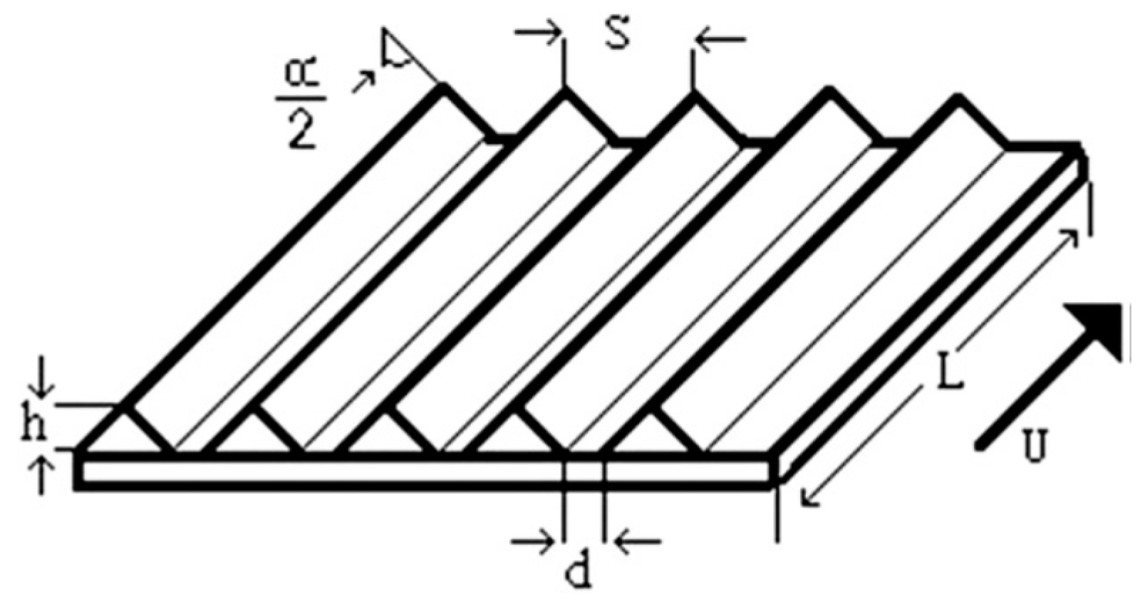
An innovative approach to reduce the drag caused by separation is to partially or fully cover the wind turbine blade/airfoil with rib-lets which are less costly and easily available. Its basic principle involves covering the surface of a blade with a rough film causing the separation to delay as shown in Figure 15. It is a type of passive flow control technique, which doesn’t require energy to operate it. It was found that rib-lets reduce the drag force, and the amount of decrease depends on the height of attached film. A study was carried out to obtain the optimum rib-let shape and size. A maximum of 6% and 4% reduction in the drag was obtained with V-groove rib-let (Figure 16) when it was completely covering the blade and partially covering the blade respectively, Chamorro et al. [169].
Another passive flow control technique using slotted airfoils, as shown in Figure 17, has been studied by Belamadi et al. [170]. A 2D CFD analysis was carried out to study the effect of location width and slope of the slot on the separation. This control system was found to increase the aerodynamic performance around 10° to 20° of angle of attack. Out of this range, the baseline configuration outperformed the slot configuration. MacPhee and Beyene [158] experimentally and numerically examined the potential of using wind turbine blade flexible purposely as a passive flow control technique. It was found that flexible blades i.e., morphing the blades, are superior to rigid one in terms of the maximum torque developed and the coefficient of power (CP). The torque was shown to increase up to 26% and CP to increase up to 43%. The operational range was also found to increase by 67%. Morphing also helps wind turbine adapt to varying load conditions in addition to act a passive flow control technique as mentioned above. Binci et al. [171] studied the flow field past a dimpled laminar airfoil using Computational Fluid-Dynamics (CFD) to analyze the flow field induced by dimples on the NACA 64-014A laminar airfoil at Re = 1.75 × 10⁵ at α = 0°. Large-Eddy Simulation results provided good agreement with experimental data, while Reynolds Averaged Navier-Stokes equations approach overestimated the laminar separation bubble (LSB) extension of dimpled and un-dimpled configurations.
10. Stall Control
When horizontal axis wind turbine blades are subjected to high wind speed, their angle of attack inherently increases. At an increased angle of attack, the lift coefficient reduces drastically which is known as stall. It occurs as soon as the separation of boundary layer takes place and eventually influences the aerodynamic loads. The discrepancies in the results of wind turbine found in the literature between the predicted and measured performance are majorly due to the rotation of wind turbine blade which is not considered while predicting using the simple theories such as BEM and vortex lattice (VL). To study the effect of rotation, Du and Selig [172] solved 3-D integral boundary layer equations. The separation point, stall on a rotating blade was delayed compared to the non-rotating blade. Further numerical and experimental analysis by Hu et al. [173] showed that the Coriolis and centrifugal forces are the notable factors for beneficial effect of rotation which results in an increased lift and decreased drag. The centrifugal force produces an outflow in separation regions which in turn causes a Coriolis force that acts along the chord of the blade which delays the separation further downstream. The investigation carried out by Wood [174] supports the above argument. By analyzing the turbine under fully 3-D technique, it was found that the negative pressure at the leading edge, could be reduced and a delay in boundary layer separation could be observed. Delay in separation will result in higher CL and reduced CD and a net increase in CP. To further illustrate the effect of rotation, an experimental study was conducted by Lee and Wu [175] where they demonstrated that reversed flow is larger for a static airfoil. The experimental analysis was carried out using Tomographic particle image velocimetry (Tomo-PIV) which measured volumetric velocity fields in all three directions. A larger angle of attack resulted due to larger Coriolis forces which delayed the stall on the turbine blades. Foussekis et al. [176] presented the effect of steady and unsteady separated flow around an airfoil experimentally and numerically to quantify the phenomenon of stall, in which they found a double separation on the studied profile. Although, most utility wind turbines operate at constant speed, but there has been a considerable interest in variable-speed turbines. The following advantages are expected for a wind turbine operated under variable-speed configuration.
- (1)
- Increase the energy capture
- (2)
- Drivetrain loads are reduced
- (3)
- Run smoothly
- (4)
- The quality of power is enhanced
- (5)
- Most importantly, doesn’t require a flow control technique which burdens the turbine mechanically and economically.
Muljadi et al. [177] evaluated variable speed wind turbine regulated by stall which claims to have a lower energy cost due to the absence of flow control technique causing merely no maintenance cost. They found that, at slow and medium wind speeds, the turbine is made to run at maximum efficiency, and at high wind speeds, the rotational speed is limited hence output power by forcing the rotor to stall, known as soft-stall.
11. Cut-in-Speed Reduction Techniques
Wind turbines usually perform poor at low wind speed, hence low Reynolds number, due to laminar flow separation. Flow separation on airfoils is particularly prevalent at low Reynolds number (Re) due to the interaction of the laminar boundary layer on the suction surface with an adverse pressure gradient. The momentum contained in the boundary layer is often unable to withstand the forces imposed by the adverse pressure gradient, which causes the flow to separate near the leading edge. The streamlines over an airfoil blade showed that the flow separates at low velocities at the inboard section of blades, Lu et al. [80]. Wind turbines are expected to generate power over a wide range of wind speeds. The minimum wind speed at which wind turbines can generate power at is known as cut-in-speed of the wind turbine. For better performance of wind turbines over a wide range of wind speed, the cut-in-speed of the wind turbines should be reduced through proper designing of blades. A specially designed airfoil which was able to reduce the cut-in speed when tested in low wind speed applications has been presented by Singh et al. [178]. An increased taper and twist to the airfoil cross-section was able to increase the coefficient power in addition to decreasing the cut-in speed. Experiments were conducted to determine the optimum pitch angle of the blade, and the resulting cut-in-speed at the optimum pitch angle was found to be 3.24 m/s which is less than the baseline configuration speed of 3.58 m/s.
12. Starting Behavior of the Wind Turbines
Large wind turbines are generally started by the generator operated as a motor due to the fact that the starting mechanism is a complex combination of unsteadiness, large angle of attack, very low Reynolds number, and other factors. Once a turbine starts rotating, it accelerates and generates unexpectedly high torque. Starting mechanism can have a large effect on the economics of a turbine at a particular site. Moreover, small turbines cannot be incorporated with the motor when they are located in remote areas. Surprisingly, rare research has been found in the open literature on this topic. A BEM analysis is carried out by Ebert and Wood [179] highlighted the starting behaviour of a horizontal axis wind turbine using two field sets of wind speeds. During starting, the blades are pitched back from their starting location due to unsteadiness. The authors observed that the pitching for both the field sets occurred too quickly causing the angle of attack to increase. This reduces the torque developed and hence requires a longer time for a turbine to start.
A study conducted by Pourrajabian et al. [180], reported that the use of hollow blades for reducing the starting time without affecting the output power and the stress not exceeding the allowable limits. The blade allowable stress is a constraint in reducing the mass of the blade. BEM theory combined with simple beam theory was employed to compute the power, starting time, stress and deflection. Scappatici et al. [181] proposed a laboratory to market approach for the design of blades made of glass fiber-reinforced polymer for small wind turbines. Finite Element Method was employed for numerical simulation of the distribution of the stresses along the blade. A mean difference of 3.8% between simulated and measured modal frequencies was recorded, and a maximum variation of 6.8% was obtained in strain values.
13. Wind Turbine Blade Materials
The global wind industry is growing fast, in terms of both the number of turbines and their sizes. Wind turbine blades typically consist of reinforcement fibers, such as glass fibers or carbon fibers; a plastic polymer, such as polyester or epoxy; sandwich core materials such as polyvinyl chloride (PVC), polyethylene terephthalate (PET) or balsa wood; and bonded joints, coating (polyurethane), and lightning conductors. Wind turbine blades are expected to have a lifecycle of around 20–25 years. The question is what to do with them afterwards, Kari [182]. Most of the wind turbine blades are constructed using Fiber Reinforced Plastics (FRPs). These composite materials are considered as anisotropic. Jackson et al. [183] investigated the design and manufacturing issues for wind turbine blades in 1–10 MW range. Two types of materials were considered for the manufacturing of the blades. The first blade was made of fibreglass for the skin and spar and the second one incorporated carbon into the spar which benefits in terms of blade deflection. In September 2008, Risoe Technical University of Denmark (DTU) announced it is aiding the Chinese forestry commission to examine the use of bamboo in wind turbine blades. The blades will initially be made from bamboo shreds glued together using epoxy, but the hope is to be able to replace the synthetic epoxy material with a bio-based adhesive. Wind turbine blades are critical components of wind energy systems because their aerodynamics, weight, and structural properties are critical for energy capture. Due to increasing demand of larger wind turbines, blade designs have been developed to optimize the material properties, performance, and the economics. Blade lengths have steadily increased over time, from 12 m or 15 m in the 1980s (Brøndsted et al. [184]) to the recent launch of 80 m blade.
Blades are subjected to both bending and torsion. Bending is encountered in flapwise direction whereas an elastic twist exists along the axis of the blade. The conventional design concepts deal with both of these separately, which provides lower stress concentrations than actual values at the leading edge joints. To overcome this deviation, coupling bending-torsion is suggested in designing the wind turbine blade, Goeij et al. [185]. The results, so obtained were in good agreement with the experimental values. The effect of morphing the blade on the elasticity has been studied by Puterbaugh and Beyene [186]. Morphing was found to act as a passive flow control technique as well as help the blade adapt to varying load conditions. Results suggested that the morphing blades could be modelled as a non-prismatic cantilever beam and a relationship was established between the airfoil’s thickness and the elasticity.
As the global wind industry grows in both number of turbines and size, so does the future waste stream of rotor blade material, Cherrington et al. [187]. The globally increasing expansion of wind power deployment is creating a growing waste disposal issues associated with the decommissioning of wind turbine blades in the time to come, Cherrington et al. [187]. The average recyclability of the components of wind turbines has been reported to be about 80% by mass. The composite WT blades present a challenge for waste management. Cherrington et al. [187] considered the producer responsibility scenarios for manufacturers to recycle wind turbine blades and investigated the current and future methods of blade disposal with specific objective of adding carbon fiber to the recyclability of blade systems. Asl et al. [188] designed and manufactured two sets of scaled-down composite I-beams representing the spar cap and the shear web geometry of a utility-scale blade made from a conventional epoxy-resin system and from bio-based resin system. The beams were loaded in a quasi-static four-point bending test configuration, and the strain fields of their flanges were measured using digital image correlation. The results showed that the flexural stiffness of the bio-based resin beams was comparable with the conventional-resin based beams.
14. Concluding Remarks
Kingdom of Saudi Arabia has initiated the program of utilizing wind power in its existing energy portfolio. Accordingly, wind power resource assessment campaign, wind farm design, optimization, and power grid system integration studies have been initiated. The present effort of understanding the nature of wind power technological developments, existing performance enhancement methodologies, and developing local expertise and facilities is an initiative to contribute towards the national wind energy development and deployment program. More than 150 research papers, reports, books and material from different sources have been collected and reviewed. It has been noted that wind power technology is fully matured and commercially acceptable by majority of nations whether developed or developing. With regard to wind turbine blade design and performance enhancement, theoretical, analytical, numerical and experimental approaches have been used widely and hence to be adopted here in the Kingdom as well. It has been observed that wind turbine performance optimization has been performed based on single objective basis such as maximization of annual energy yield; minimization of blade loads, cost of energy, and root moment; etc. Hence there is an urgent need to develop methodologies to measure the performance of the wind turbines based on multi objective issues as mentioned. However, with limited literature on multi-objective analysis of wind turbine blade efficiency improvement, concurrent-hybrid non-dominated sorting genetic algorithm is being used for the optimization of the annual energy production, flapwise root-bending moment and mass of the wind-turbine blade. The review provided in this study will be very useful to researchers, academicians, students, and consultants who are planning to work on wind turbine efficiency enhancement, optimization and its performace evaluation.
Acknowledgments
The authors would like to acknowledge the support provided by the Deanship of Scientific Research (DSR) at King Fahd University of Petroleum & Minerals (KFUPM) for funding this work through Grant number IN151026.
Author Contributions
Shafiqur Rehman conceived the idea of writing a review paper on the performance enhancement methodologies of horizontal axis wind turbine blades. He collected the relevant material with the help of Luai M. Alhems, Md. Mahbub Alam, and M. Mujahid Rafique. The paper was written by Shafiqur Rehman and was reviewed by other three co-authors.
Conflicts of Interest
The authors declare no conflict of interest.
Nomenclature
| AEY | Annual Energy Yield |
| AIF | Axial Induction Factor |
| BEM | Blade Element Momentum theory |
| BF | Blade Fatigue |
| BM | Blade Mass |
| BK | Buckling |
| COE | Cost of Energy |
| CFD | Computational Fluid Dynamics |
| CKS | Control Kind of Stall |
| DRT | Drive Train |
| DT | Displacement |
| DSF | Damage and Static Failure |
| FEM | Finite Element Modeling |
| GC | Ground Clearance |
| GCI | Grid Convergence Index |
| GRE | General Richardson Extrapolation |
| GW | Giga Watt |
| HAWT | Horizontal Axis Wind Turbine |
| HH | Hub Height |
| HWA | Hot Wire Anemometry |
| kW | Kilo Watt |
| kWh | Kilo Watt hour |
| LI | Linear Inequality |
| LSV | Laser Sheet Visualization |
| MC | Maximum Chord |
| MW | Mega Watt |
| MWh | Mega Watt hour |
| NF | Natural Frequency |
| NL | Noise Level |
| PIV | Particle Image Velocimetry |
| RP | Rated Power |
| SN | Strain |
| SS | Stress |
| SL | Solidity |
| SAT | Shell and Airfoil Thickness |
| SP | Separation Point |
| SFV | Smoke Flow Visualization |
| ST | Shaft Torque |
| TV | Tower Vibrations |
| TR | Thrust |
| VAWT | Vertical axis wind turbine |
| WFA | Wind Farm Area |
| WTP | Wind Turbine Power |
| CD | Drag coefficient |
| CL | Lift coefficient |
| CP | Power coefficient |
References
- Soler-Bientz, R. Preliminary results from a network of stations for wind resource assessment at North of Yucatan Peninsula. Energy 2011, 36, 538–548. [Google Scholar] [CrossRef]
- Global Wind Report (GWEC). Available online: http://www.gwec.net/wp-content/uploads/vip/GWEC_PRstats2016_EN_WEB.pdf (accessed on 11 January 2018).
- Wind Turbine Schematic. Available online: http://www.delahyde.com/lubang/imagesl_2013/Wind_Turbine_Schematic_M.jpg (accessed on 11 January 2018).
- Tsai, K.; Pan, C.; Cooperman, A.M.; Johnson, S.J.; Dam, C.P. Van An Innovative Design of a Microtab Deployment Mechanism for Active Aerodynamic Load Control. Energies 2015, 8, 5885–5897. [Google Scholar] [CrossRef]
- Fernandez-gamiz, U.; Zulueta, E.; Boyano, A.; Ramos-hernanz, J.A.; Lopez-guede, J.M. Microtab Design and Implementation on a 5 MW Wind Turbine. Appl. Sci. 2017, 7, 536. [Google Scholar] [CrossRef]
- KACARE White Paper. Available online: https://www.kacare.gov.sa/en/FutureEnergy/RenewableEnergy/Pages/default.aspx (accessed on 11 January 2018).
- Elsevier BV. Scopus Journal Analyzer. 2014. Available online: http://www.scopus.com/source/eval.url (accessed on 11 January 2018).
- Zheng, Q.; Rehman, S.; Alam, M.; Alhems, L.M.; Lashin, A. Decomposition of wind speed fluctuations at different time scales. J. Earth Syst. Sci. 2017, 126. [Google Scholar] [CrossRef]
- Alam, M.M.; Rehman, S.; Al-Hadhrami, L.M.; Meyer, J.P. Extraction of the inherent nature of wind speed using wavelets and FFT. Energy Sustain. Dev. 2014, 22, 34–47. [Google Scholar] [CrossRef]
- Siddiqi, A.H.; Khan, S.; Rehman, S. Wind Speed Simulation Using Wavelets. Am. J. Appl. Sci. 2005, 2, 557–564. [Google Scholar] [CrossRef]
- Rehman, S.; Ali, S.; Khan, S. Wind Farm Layout Design Using Cuckoo Search Algorithms. Appl. Artif. Intell. 2016, 30, 899–9224. [Google Scholar] [CrossRef]
- Rehman, S.; Khan, S. Fuzzy Logic Based Multi-Criteria Wind Turbine Selection Strategy—A Case Study of Qassim, Saudi Arabia. Energies 2016, 9, 872. [Google Scholar] [CrossRef]
- Shoaib, M.; Siddiqui, I.; Rehman, S.; Rehman, S.; Khan, S.; Lashin, A. Comparison of Wind Energy Generation Using the Maximum Entropy Principle and the Weibull Distribution Function. Energies 2016, 9, 842. [Google Scholar] [CrossRef]
- Mohandes, M.; Rehman, S.; Abido, M.; Badran, S. Convertible wind energy based on predicted wind speed at hub-height. Energy Sources Part A Recover. Util. Environ. Eff. 2016, 38, 140–148. [Google Scholar] [CrossRef]
- Mohandes, M.; Rehman, S.; Rahman, S.M. Estimation of wind speed profile using adaptive neuro-fuzzy inference system (ANFIS). Appl. Energy 2011, 88, 4024–4032. [Google Scholar] [CrossRef]
- Mohandes, M.A.; Rehman, S.; Rahman, S.M. Spatial estimation of wind speed. Int. J. Energy Res. 2012, 36, 545–552. [Google Scholar] [CrossRef]
- Mohandes, M.A.; Rehman, S. Short term wind speed estimation in Saudi Arabia. J. Wind Eng. Ind. Aerodyn. 2014, 128, 37–53. [Google Scholar] [CrossRef]
- Mohandes, M.A.; Halawani, T.O.; Rehman, S.; Hussain, A.A. Support vector machines for wind speed prediction. Renew. Energy 2004, 29, 939–947. [Google Scholar] [CrossRef]
- Mohandes, M.A.; Rehman, S.; Halawani, T.O. A neural networks approach for wind speed prediction. Renew. Energy 1998, 13, 645–654. [Google Scholar] [CrossRef]
- Bagiorgas, H.S.; Mihalakakou, G.; Rehman, S.; Al-Hadhrami, L.M. Wind power potential assessment for three buoys data collection stations in the Ionian Sea using Weibull distribution function. Int. J. Green Energy 2016, 13, 703–714. [Google Scholar] [CrossRef]
- Bagiorgas, H.S.; Mihalakakou, G.; Rehman, S.; Al-Hadhrami, L.M. Offshore wind speed and wind power characteristics for ten locations in Aegean and Ionian Seas. J. Earth Syst. Sci. 2012, 121, 975–987. [Google Scholar] [CrossRef]
- Bagiorgas, H.S.; Mihalakakou, G.; Rehman, S.; Al-Hadhrami, L.M. Wind power potential assessment for seven buoys data collection stations in Aegean Sea using Weibull distribution function. J. Renew. Sustain. Energy 2012, 4. [Google Scholar] [CrossRef]
- Bagiorgas, H.S.; Giouli, M.; Rehman, S.; Al-Hadhrami, L.M. Weibull parameters estimation using four different methods and most energy-carrying wind speed analysis. Int. J. Green Energy 2011, 8, 529–554. [Google Scholar] [CrossRef]
- Rehman, S.; Al-hadhrami, L.M.; Bagiorgas, H.S. Offshore Wind Characteristics in Ionian Sea. Trans. Control Mech. Syst. 2012, 1, 229–234. [Google Scholar]
- Himri, Y.; Rehman, S.; Himri, S.; Mohammadi, K.; Sahin, B.; Malik, A.S. Investigation of wind resources in Timimoun region, Algeria. Wind Eng. 2016, 40, 250–260. [Google Scholar] [CrossRef]
- Himri, Y.; Rehman, S.; Agus Setiawan, A.; Himri, S. Wind energy for rural areas of Algeria. Renew. Sustain. Energy Rev. 2012, 16, 2381–2385. [Google Scholar] [CrossRef]
- Himri, Y.; Rehman, S.; Draoui, B.; Himri, S. Wind power potential assessment for three locations in Algeria. Renew. Sustain. Energy Rev. 2008, 12, 2488–2497. [Google Scholar] [CrossRef]
- Khan, S.A.; Rehman, S. Iterative non-deterministic algorithms in on-shore wind farm design: A brief survey. Renew. Sustain. Energy Rev. 2013, 19, 370–384. [Google Scholar] [CrossRef]
- Bassyouni, M.; Gutub, S.; Javaid, U.; Awais, M.; Rehman, S.; Abdel-Hamid, S.; Abdel-Aziz, M.; Abouel-Kasem, A.; Shafeek, H. Assessment and analysis of wind power resource using weibull parameters. Energy Explor. Exploit. 2015, 33, 105–122. [Google Scholar] [CrossRef]
- Baseer, M.A.; Meyer, J.P.; Alam, M.M.; Rehman, S. Wind speed and power characteristics for Jubail industrial city, Saudi Arabia. Renew. Sustain. Energy Rev. 2015, 52, 1193–1204. [Google Scholar] [CrossRef]
- Rehman, S.; El-Amin, I.M.; Ahmad, F.; Shaahid, S.M.; Al-Shehri, A.M.; Bakhashwain, J.M. Wind power resource assessment for Rafha, Saudi Arabia. Renew. Sustain. Energy Rev. 2007, 11, 937–950. [Google Scholar] [CrossRef]
- Rehman, S.; Alam, M.M.; Meyer, J.P.; Al-Hadhrami, L.M. Wind speed characteristics and resource assessment using Weibull parameters. Int. J. Green Energy 2012, 9, 800–814. [Google Scholar] [CrossRef]
- Rehman, S.; Halawani, T.O.; Mohandes, M. Wind power cost assessment at twenty locations in the Kingdom of Saudi Arabia. Renew. Energy 2003, 28, 573–583. [Google Scholar] [CrossRef]
- Rehman, S.; Ahmad, A. Assessment of wind energy potential for coastal locations of the Kingdom of Saudi Arabia. Energy 2004, 29, 1105–1115. [Google Scholar] [CrossRef]
- Proietti, S.; Sdringola, P.; Castellani, F.; Astolfi, D.; Vuillermoz, E. On the contribution of renewable energies for feeding a high altitude Smart Mini Grid. Appl. Energy 2017, 185, 1694–1701. [Google Scholar] [CrossRef]
- Rehman, S. Wind energy resources assessment for Yanbo, Saudi Arabia. Energy Convers. Manag. 2004, 45, 2019–2032. [Google Scholar] [CrossRef]
- Rehman, S. Offshore wind power assessment on the east coast of Saudi Arabia. Wind Eng. 2005, 29, 409–419. [Google Scholar] [CrossRef]
- Rehman, S.; Ahmad, A.; El-Amin, I.; Al-Hadhrami, L.M. Assessment of wind power, wind exponent, local air density and air turbulence intensity for an isolated site. Int. J. Sustain. Energy 2009, 28, 217–230. [Google Scholar] [CrossRef]
- Rehman, S.; Sahin, A.Z. A wind-solar PV hybrid power system with battery backup for water pumping in remote localities. Int. J. Green Energy 2016, 13, 1075–1083. [Google Scholar] [CrossRef]
- Ur Rehman, S.; Rehman, S.; Qazi, M.U.; Shoaib, M.; Lashin, A. Feasibility study of hybrid energy system for off-grid rural electrification in southern Pakistan. Energy Explor. Exploit. 2016, 34, 468–482. [Google Scholar] [CrossRef]
- Rehman, S.; El-Amin, I. Study of a solar pv/wind/diesel hybrid power system for a remotely located population near Arar, Saudi Arabia. Energy Explor. Exploit. 2015, 33, 591–620. [Google Scholar] [CrossRef]
- Rehman, S.; Alam, M.M.; Meyer, J.P.; Al-Hadhrami, L.M. Feasibility study of a wind-pv-diesel hybrid power system for a village. Renew. Energy 2012, 38, 258–268. [Google Scholar] [CrossRef]
- Rehman, S.; Al-Hadhrami, L.M. Study of a solar PV-diesel-battery hybrid power system for a remotely located population near Rafha, Saudi Arabia. Energy 2010, 35, 4986–4995. [Google Scholar] [CrossRef]
- Rehman, S.; El-Amin, I.M.; Ahmad, F.; Shaahid, S.M.; Al-Shehri, A.M.; Bakhashwain, J.M.; Shash, A. Feasibility study of hybrid retrofits to an isolated off-grid diesel power plant. Renew. Sustain. Energy Rev. 2007, 11, 635–653. [Google Scholar] [CrossRef] [Green Version]
- Rehman, S. Prospects of wind farm development in Saudi Arabia. Renew. Energy 2005, 30. [Google Scholar] [CrossRef]
- Rehman, S.; Baseer, M.A.; Meyer, J.P.; Alam, M.M.; Alhems, L.M.; Lashin, A.; Al Arifi, N. Suitability of utilizing small horizontal axis wind turbines for off grid loads in eastern region of Saudi Arabia. Energy Explor. Exploit. 2016, 34, 449–467. [Google Scholar] [CrossRef]
- Rehman, S. Performance Evaluation of Vertical Axis Wind Turbine for Small off grid loads in North-Eastern Region of Saudi Arabia Performance Evaluation of Vertical Axis Wind Turbine for Small off grid loads in North-Eastern Region of Saudi Arabia. Wulfenia J. 2015, 22, 146–165. [Google Scholar]
- Rehman, S.; Sahin, A. Comparing the use of diesel and wind power in pumping water in Saudi Arabia. Energy Environ. 2014, 25, 369–388. [Google Scholar] [CrossRef]
- Rehman, S.; Sahin, A.Z. Wind power utilization for water pumping using small wind turbines in Saudi Arabia: A techno-economical review. Renew. Sustain. Energy Rev. 2012, 16, 4470–4478. [Google Scholar] [CrossRef]
- Baseer, M.A.; Meyer, J.P.; Rehman, S.; Alam, M.M.; Al-Hadhrami, L.M.; Lashin, A. Performance evaluation of cup-anemometers and wind speed characteristics analysis. Renew. Energy 2016, 86, 733–744. [Google Scholar] [CrossRef]
- Rehman, S. Tower distortion and scatter factors of co-located wind speed sensors and turbulence intensity behavior. Renew. Sustain. Energy Rev. 2014, 34, 20–29. [Google Scholar] [CrossRef]
- Rehman, S.; Al-Hadhrami, L.M.; Alam, M.M.; Meyer, J.P. Empirical correlation between hub height and local wind shear exponent for different sizes of wind turbines. Sustain. Energy Technol. Assess. 2013, 4, 45–51. [Google Scholar] [CrossRef]
- Alam, M.M.; Rehman, S.; Meyer, J.P.; Al-Hadhrami, L.M. Review of 600–2500 kW sized wind turbines and optimization of hub height for maximum wind energy yield realization. Renew. Sustain. Energy Rev. 2011, 15, 3839–3849. [Google Scholar] [CrossRef]
- Rehman, S. Long-term wind speed analysis and detection of its trends using Mann-Kendall test and linear regression method. Arab. J. Sci. Eng. 2013, 38, 421–437. [Google Scholar] [CrossRef]
- Rahman, F.; Rehman, S.; Abdul-Majeed, M.A. Overview of energy storage systems for storing electricity from renewable energy sources in Saudi Arabia. Renew. Sustain. Energy Rev. 2012, 16, 274–283. [Google Scholar] [CrossRef]
- Rehman, S.; Ahmad, A.; Al-Hadhrami, L.M. Development and economic assessment of a grid connected 20 MW installed capacity wind farm. Renew. Sustain. Energy Rev. 2011, 15, 833–838. [Google Scholar] [CrossRef]
- Rehman, S.; Ahmad, A.; Al-Hadhrami, L.M. Detailed analysis of a 550-MW installed capacity wind farm in Saudi Arabia. Int. J. Green Energy 2010, 7, 410–421. [Google Scholar] [CrossRef]
- Rehman, S.; Al-Abbadi, N.M. Wind power characteristics on the North West coast of Saudi Arabia. Energy Environ. 2009, 20–21, 1257. [Google Scholar] [CrossRef]
- Al-Abbadi, N.M.; Rehman, S. Wind speed and wind power characteristics for Gassim, Saudi Arabia. Int. J. Green Energy 2009, 6, 201–217. [Google Scholar] [CrossRef]
- Rehman, S.; Al-Abbadi, N.M. Wind shear coefficient, turbulence intensity and wind power potential assessment for Dhulom, Saudi Arabia. Renew. Energy 2008, 33, 2653–2660. [Google Scholar] [CrossRef]
- Rehman, S.; Al-Abbadi, N.M. Wind shear coefficients and energy yield for Dhahran, Saudi Arabia. Renew. Energy 2007, 32, 738–749. [Google Scholar] [CrossRef]
- Rehman, S.; Al-Abbadi, N.M. Wind shear coefficients and their effect on energy production. Energy Convers. Manag. 2005, 46, 2578–2591. [Google Scholar] [CrossRef]
- Rehman, S.; Halawani, T.O. Statistical characteristics of wind in Saudi Arabia. Renew. Energy 1994, 4, 949–956. [Google Scholar] [CrossRef]
- Rehman, S.; Halawani, T.O.; Husain, T. Weibull parameters for wind speed distribution in Saudi Arabia. Sol. Energy 1994, 53, 473–479. [Google Scholar] [CrossRef]
- Alam, M.; Rehman, S.; Al-hadhrami, L.M.; Russel, M.; Meyer, J.P. Quantifying the contributions of different time-scales to wind speed using wavelets. In Proceedings of the International Conference on Mechanical, Industrial and Energy Engineering, Khulna, Bangladesh, 25–26 December 2014. [Google Scholar]
- Manwell, J.F.; McGowan, J.G.; Rogers, A.L. Wind Energy Explained: Theory, Design and Application; John Wiley & Sons: Hoboken, NJ, USA, 2010. [Google Scholar]
- Wind Power. 2014. Available online: http://energystorage.org/energy-storage/applications-energy-storage-technology (accessed on 11 January 2018).
- Fthenakis, V.; Kim, H.C. Land use and electricity generation: A life-cycle analysis. Renew. Sustain. Energy Rev. 2009, 13, 1465–1474. [Google Scholar] [CrossRef]
- Wind Energy Technologies and Applications. Available online: https://energy.gov/sites/prod/files/2016/08/f33/2015-Wind-Technologies-Market-Report-08162016.pdf (accessed on 11 January 2018).
- Goldstein, L. A proposal and a theoretical analysis of a novel concept of a tilted-axis wind turbine. Energy 2015, 84, 247–254. [Google Scholar] [CrossRef]
- Ohya, Y.; Karasudani, T. A Shrouded Wind Turbine Generating High Output Power with Wind-lens Technology. Energies 2010, 3, 634–649. [Google Scholar] [CrossRef]
- Savonius Wind Power Report. Available online: http://www.uvm.edu/extension/cropsoil/wp-content/uploads/savonius_windpower_report.pdf (accessed on 11 January 2018).
- Chen, J.; Yang, H.; Yang, M.; Xu, H.; Hu, Z. A comprehensive review of the theoretical approaches for the airfoil design of lift-type vertical axis wind turbine. Renew. Sustain. Energy Rev. 2015, 51, 1709–1720. [Google Scholar] [CrossRef]
- Kress, C.; Chokani, N.; Abhari, R.S. Passive minimization of load fluctuations on downwind turbines. Renew. Energy 2016, 89, 543–551. [Google Scholar] [CrossRef]
- Morcos, V.H. Aerodynamic performance analysis of horizontal axis wind turbines. Renew. Energy 1994, 4, 505–518. [Google Scholar] [CrossRef]
- Malhotra, P.; Hyers, R.W.; Manwell, J.F.; McGowan, J.G. A review and design study of blade testing systems for utility-scale wind turbines. Renew. Sustain. Energy Rev. 2012, 16, 284–292. [Google Scholar] [CrossRef]
- Ma, P.C.; Zhang, Y. Perspectives of carbon nanotubes/polymer nanocomposites for wind blade materials. Renew. Sustain. Energy Rev. 2014, 30, 651–660. [Google Scholar] [CrossRef]
- White, F. Fluid Mechanics, 8th ed.; McGraw-Hill: New York, NY, USA, 2015. [Google Scholar]
- Moshfeghi, M.; Song, Y.J.; Xie, Y.H. Effects of near-wall grid spacing on SST-K-ω model using NREL Phase VI horizontal axis wind turbine. J. Wind Eng. Ind. Aerodyn. 2012, 107–108, 94–105. [Google Scholar] [CrossRef]
- Lu, K.; Xie, Y.; Zhang, D.; Xie, G. Systematic investigation of the flow evolution and energy extraction performance of a flapping-airfoil power generator. Energy 2015, 89, 138–147. [Google Scholar] [CrossRef]
- Chang, J.; Zhu, W.; Fischer, A.; Garcla, N.R.; Madsen, J.; Chen, J.; Shen, W.Z. Design and validation of the high performance and low noise CQU-DTU-LN1 airfoils. Wind Energy 2014, 17, 1817–1833. [Google Scholar] [CrossRef]
- Yavuz, T.; Koc, E.; Kilkis, B.; Erol, O.; Balas, C.; Aydemir, T. Performance analysis of the airfoil-slat arrangements for hydro and wind turbine applications. Renew. Energy 2015, 74, 414–421. [Google Scholar] [CrossRef]
- Singh, R.K.; Ahmed, M.R.; Zullah, M.A.; Lee, Y.-H. Design of a low Reynolds number airfoil for small horizontal axis wind turbines. Renew. Energy 2012, 42, 66–76. [Google Scholar] [CrossRef]
- Devinant, P.; Laverne, T.; Hureau, J. Experimental study of wind-turbine airfoil aerodynamics in high turbulence. J. Wind Eng. Ind. Aerodyn. 2002, 90, 689–707. [Google Scholar] [CrossRef]
- McTavish, S.; Feszty, D.; Nitzsche, F. Evaluating Reynolds number effects in small-scale wind turbine experiments. J. Wind Eng. Ind. Aerodyn. 2013, 120, 81–90. [Google Scholar] [CrossRef]
- Bons, J.P.; Sondergaard, R.; Rivir, R.B. The Fluid Dynamics of LPT Blade Separation Control Using Pulsed Jets. J. Turbomach. 2002, 124, 77. [Google Scholar] [CrossRef]
- Gul, M.; Uzol, O.; Akmandor, I.S. An Experimental Study on Active Flow Control Using Synthetic Jet Actuators over S809 Airfoil. J. Phys. Conf. Ser. 2014, 524, 12101. [Google Scholar] [CrossRef]
- Aramendia, I.; Fernandez-Gamiz, U.; Ramos-Hernanz, J.; Sancho, J.; Lopez-Guede, J.; Zulueta, E. Flow Control Devices for Wind Turbines; Springer International Publishing: Munchem, Germany, 2017; pp. 629–655. [Google Scholar]
- Aramendia, I.; Fernández-Gámiz, U.; Sancho, J.; Zulueta, E. State of the Art of Active and Passive Flow Control. Fluid Mech. 2016, 1–9. [Google Scholar] [CrossRef]
- Abdulrahim, A.; Anik, E.; Ostovan, Y.; Uzol, O. Effects of tip injection on the performance and near wake characteristics of a model wind turbine rotor. Renew. Energy 2016, 88, 73–82. [Google Scholar] [CrossRef]
- Gharali, K.; Johnson, D.A. Numerical modeling of an S809 airfoil under dynamic stall, erosion and high reduced frequencies. Appl. Energy 2012, 93, 45–52. [Google Scholar] [CrossRef]
- Sutherland, H.; Beattie, A.; Hansche, B.; Musial, W.; Allread, J.; Johnson, J.; Summers, M. The Application of Non-Destructive Techniques to the Testing of a Wind Turbine Blade; Sandia National Laboratories: Springfield, VA, USA, 1994; p. 22161.
- Zarouchas, D.S.; Makris, A.A.; Sayer, F.; Van Hemelrijck, D.; Van Wingerde, A.M. Investigations on the mechanical behavior of a wind rotor blade subcomponent. Compos. Part B 2012, 43, 647–654. [Google Scholar] [CrossRef]
- Asl, M.; Niezrecki, C.; Sherwood, J.; Peter, A. Scaled Composite I-Beams for Subcomponent Testing of Wind Turbine Blades: An Experimental Study. In Mechanics of Composite and Multi-Functional Materials; Springer International Publishing: Munchem, Germany, 2018; pp. 71–78. [Google Scholar]
- Asl, M.E.; Niezrecki, C.; Sherwood, J.; Avitabile, P. Similitude analysis of thin-walled composite I-beams for subcomponent testing of wind turbine blades. Wind Eng. 2017, 41, 297–312. [Google Scholar] [CrossRef]
- Lee, S.G.; Park, S.J.; Lee, K.S.; Chung, C. Performance prediction of NREL (National Renewable Energy Laboratory) Phase VI blade adopting blunt trailing edge airfoil. Energy 2012, 47, 47–61. [Google Scholar] [CrossRef]
- Wood, D.H. Some effects of compressibility on small horizontal-axis wind turbines. Renew. Energy 1997, 10, 11–17. [Google Scholar] [CrossRef]
- Almohammadi, K.M.; Ingham, D.B.; Ma, L.; Pourkashan, M. Computational fluid dynamics (CFD) mesh independency techniques for a straight blade vertical axis wind turbine. Energy 2013, 58, 483–493. [Google Scholar] [CrossRef]
- Whale, J.; Fisichella, C.J.; Selig, M.S. Correcting Inflow Measurements from Wind Turbines Using a Lifting-Surface Code. J. Sol. Energy Eng. 2000, 122, 196–202. [Google Scholar] [CrossRef]
- Giguère, P.; Selig, M.S.; Tangler, J.L. Blade Design Trade-Offs Using Low-Lift Airfoils for Stall-Regulated HAWTs. J. Sol. Energy Eng. 1999, 121, 217–223. [Google Scholar] [CrossRef]
- Selig, M.S.; Tangler, J.L. Development and Application of a Multipoint Inverse Design Method for Horizontal Axis Wind Turbines. Wind Eng. 1995, 19, 91–105. [Google Scholar]
- Selig, M.S. Multipoint Inverse Design of an Infinite Cascade of Airfoils. AIAA J. 1994, 32, 774–782. [Google Scholar] [CrossRef]
- Selig, M.S.; Maughmert, M.D. Generalized Multipoint Inverse Airfoil Design. AIAA J. 1992, 30, 2618–2625. [Google Scholar] [CrossRef]
- Selig, M.S.; Maughmert, M.D. Multipoint Inverse Airfoil Design Method Based on Conformal Mapping. AIAA J. 1992, 30, 1162–1170. [Google Scholar] [CrossRef]
- Bermúdez, L.; Velázquez, A.; Matesanz, A. Viscous-inviscid method for the simulation of turbulent unsteady wind turbine airfoil flow. J. Wind Eng. Ind. Aerodyn. 2002, 90, 643–661. [Google Scholar] [CrossRef]
- Filippone, A. Airfoil inverse design and optimization by means of viscous-inviscid techniques. J. Wind Eng. Ind. Aerodyn. 1995, 56, 123–136. [Google Scholar] [CrossRef]
- Cyr, S.; Newman, B.G. Flow past two-dimensional membrane aerofoils with rear separation. J. Wind Eng. Ind. Aerodyn. 1996, 63, 1–16. [Google Scholar] [CrossRef]
- Johansen, J.; Madsen, H.A.; Gaunaa, M.; Bak, C.; Srensen, N.N. Design of a wind turbine rotor for maximum aerodynamic efficiency. Wind Energy 2009, 12, 261–273. [Google Scholar] [CrossRef]
- Rocha, P.A.C.; Rocha, H.H.B.; Carneiro, F.O.M.; da Silva, M.E.V.; de Andrade, C.F. A case study on the calibration of the k-ω SST (shear stress transport) turbulence model for small scale wind turbines designed with cambered and symmetrical airfoils. Energy 2016, 97, 144–150. [Google Scholar] [CrossRef]
- Grant, I.; Mo, M.; Pan, X.; Parkin, P.; Powell, J.; Reinecke, H.; Shuang, K.; Coton, F.; Lee, D. An experimental and numerical study of the vortex filaments in the wake of an operational, horizontal-axis, wind turbine. J. Wind Eng. Ind. Aerodyn. 2000, 85, 177–189. [Google Scholar] [CrossRef]
- Hirahara, H.; Hossain, M.Z.; Kawahashi, M.; Nonomura, Y. Testing basic performance of a very small wind turbine designed for multi-purposes. Renew. Energy 2005, 30, 1279–1297. [Google Scholar] [CrossRef]
- Wood, D. Green Energy and Technology, 1st ed.; Springer: London, UK; Dordrecht, The Netherlands; Heidelberg, Germany; New York, NY, USA; Calgary, AB, Canada, 2011; ISBN 978-1-84996-174-5. [Google Scholar]
- Sedaghat, A.; Samani, I.; Ahmadi-baloutaki, M.; El Assad, M.; Gaith, M. Computational Study on Novel circulating Aerofoils for use in Magnus wind turbine blades. Energy 2015, 91, 393–403. [Google Scholar] [CrossRef]
- Bottasso, C.L.; Croce, A.; Gualdoni, F.; Montinari, P. Load mitigation for wind turbines by a passive aeroelastic device. J. Wind Eng. Ind. Aerodyn. 2016, 148, 57–69. [Google Scholar] [CrossRef] [Green Version]
- Han, W.; Yan, P.; Han, W.; He, Y. Design of wind turbines with shroud and lobed ejectors for efficient utilization of low-grade wind energy. Energy 2015, 89, 687–701. [Google Scholar] [CrossRef]
- Elfarra, M.A.; Sezer-Uzol, N.; Akmandor, I.S. NREL VI rotor blade: Numerical investigation and winglet design and optimization using CFD. Wind Energy 2014, 17, 657–669. [Google Scholar] [CrossRef]
- Maldonado, V.; Castillo, L.; Thormann, A.; Meneveau, C. The role of free stream turbulence with large integral scale on the aerodynamic performance of an experimental low Reynolds number S809 wind turbine blade. J. Wind Eng. Ind. Aerodyn. 2015, 142, 246–257. [Google Scholar] [CrossRef]
- Lanzafame, R.; Mauro, S.; Messina, M. Wind turbine CFD modeling using a correlation-based transitional model. Renew. Energy 2013, 52, 31–39. [Google Scholar] [CrossRef]
- Yu, G.; Shen, X.; Zhu, X.; Du, Z. An insight into the separate flow and stall delay for HAWT. Renew. Energy 2011, 36, 69–76. [Google Scholar] [CrossRef]
- Wang, F.; Bai, L.; Fletcher, J.; Whiteford, J.; Cullen, D. The methodology for aerodynamic study on a small domestic wind turbine with scoop. J. Wind Eng. Ind. Aerodyn. 2008, 96, 1–24. [Google Scholar] [CrossRef] [Green Version]
- Wang, F.; Bai, L.; Fletcher, J.; Whiteford, J.; Cullen, D. Development of small domestic wind turbine with scoop and prediction of its annual power output. Renew. Energy 2008, 33, 1637–1651. [Google Scholar] [CrossRef]
- Fagbenro, K.A.; Mohamed, M.A.; Wood, D.H. Computational modeling of the aerodynamics of windmill blades at high solidity. Energy Sustain. Dev. 2014, 22, 13–20. [Google Scholar] [CrossRef]
- Li, Y.; Castro, A.M.; Sinokrot, T.; Prescott, W.; Carrica, P.M. Coupled multi-body dynamics and CFD for wind turbine simulation including explicit wind turbulence. Renew. Energy 2015, 76, 338–361. [Google Scholar] [CrossRef]
- Li, C.; Lin, Q.; Ding, X.; Ye, X. Performance, aeroacoustics and feature extraction of an axial flow fan with abnormal blade angle. Energy 2016, 103, 322–339. [Google Scholar] [CrossRef]
- Bukala, J.; Damaziak, K.; Kroszczynski, K.; Krzeszowiec, M.; Malachowski, J. Investigation of parameters influencing the efficiency of small wind turbines. J. Wind Eng. Ind. Aerodyn. 2015, 146, 29–38. [Google Scholar] [CrossRef]
- Purazarm, P.; Modarres-Sadegh, Y.; Lackner, M. A parametric study of coupled-mode flutter for MW-size wind turbine blades. Wind Energy 2016, 19, 497–514. [Google Scholar] [CrossRef]
- Capuzzi, M.; Pirrera, A.; Weaver, P.M. A novel adaptive blade concept for large-scale wind turbines. Part II: Structural design and power performance. Energy 2014, 73, 25–32. [Google Scholar] [CrossRef]
- Capuzzi, M.; Pirrera, A.; Weaver, P.M. A novel adaptive blade concept for large-scale wind turbines. Part I: Aeroelastic behaviour. Energy 2014, 73, 15–24. [Google Scholar] [CrossRef]
- Wang, L.; Liu, X.; Kolios, A. State of the art in the aeroelasticity of wind turbine blades: Aeroelastic modelling. Renew. Sustain. Energy Rev. 2016, 64, 195–210. [Google Scholar] [CrossRef]
- Buck, J.A.; Garvey, S.D. Redefining the design objectives of large offshore wind turbine rotors. Wind Energy 2015, 18, 835–850. [Google Scholar] [CrossRef]
- Yang, H.; Shen, W.; Xu, H.; Hong, Z.; Liu, C. Prediction of the wind turbine performance by using BEM with airfoil data extracted from CFD. Renew. Energy 2014, 70, 107–115. [Google Scholar] [CrossRef]
- Sun, Z.; Chen, J.; Shen, W.Z.; Zhu, W.J. Improved blade element momentum theory for wind turbine aerodynamic computations. Renew. Energy 2016, 96, 824–831. [Google Scholar] [CrossRef]
- Sant, T. Improving BEM—Based Aerodynamic Models in Wind Turbine Design Codes Improving BEM—Based Aerodynamic Models Tonio Sant Tonio Sant Improving BEM-Based Aerodynamic Models in Wind Turbine Design Codes; Print Right Ltd., Marsa: Msida, Malta, 2007; ISBN 978-99932-0-483-1. [Google Scholar]
- Prado, R.A. Reformulation of the momentum theory applied to wind turbines. J. Wind Eng. Ind. Aerodyn. 1995, 58, 277–292. [Google Scholar] [CrossRef]
- Jamieson, P. Extraction in a Linear Constant Velocity Flow Field. Wind Energy 2008, 11, 445–457. [Google Scholar] [CrossRef]
- Liu, Y.; Yoshida, S. An extension of the Generalized Actuator Disc Theory for aerodynamic analysis of the diffuser-augmented wind turbines. Energy 2015, 93, 1852–1859. [Google Scholar] [CrossRef]
- Ohya, Y.; Karasudani, T.; Sakurai, A. Development of a shrouded wind turbine with a flanged diffuser. J. Wind Eng. Ind. Aerodyn. 2008, 96, 524–539. [Google Scholar] [CrossRef]
- Abe, K.; Nishida, M.; Sakurai, A.; Ohya, Y.; Kihara, H.; Wada, E.; Sato, K. Experimental and numerical investigations of flow fields behind a small wind turbine with a flanged diffuser. J. Wind Eng. Ind. Aerodyn. 2005, 93, 951–970. [Google Scholar] [CrossRef]
- Wang, Q.; Wang, Z.X.; Song, J.J.; Xu, Y.; Xu, J.Z. Study on a new aerodynamic model of HAWT based on panel method and Reduced Order Model using Proper Orthogonal Decomposition. Renew. Energy 2012, 48, 436–447. [Google Scholar] [CrossRef]
- Ahmed, N.; Archer, R. Testing of highly loaded horizontal axis wind turbines designed for optimum performance. Renew. Energy 2002, 25, 613–618. [Google Scholar] [CrossRef]
- Sanderson, R.J.; Archer, R.D. Optimum propeller wind turbines. J. Energy 1983, 7, 695–701. [Google Scholar] [CrossRef]
- Narayana, M.; Putrus, G.A.; Jovanovic, M.; Leung, P.S.; McDonald, S. Generic maximum power point tracking controller for small-scale wind turbines. Renew. Energy 2012, 44, 72–79. [Google Scholar] [CrossRef]
- Thumthae, C.; Chitsomboon, T. Optimal angle of attack for untwisted blade wind turbine. Renew. Energy 2009, 34, 1279–1284. [Google Scholar] [CrossRef]
- Perkin, S.; Garrett, D.; Jensson, P. Optimal wind turbine selection methodology: A case-study for Búrfell, Iceland. Renew. Energy 2015, 75, 165–172. [Google Scholar] [CrossRef]
- Pandey, M.M.; Pandey, K.P.; Ojha, T.P. An analytical approach to optimum design and peak performance prediction for horizontal axis wind turbines. J. Wind Eng. Ind. Aerodyn. 1989, 32, 247–262. [Google Scholar] [CrossRef]
- Vu, D.; Marini, I.; Milas, Z. Numerical models for robust shape optimization of wind turbine blades. Renew. Energy 2016, 87, 849–862. [Google Scholar] [CrossRef]
- Zhu, W.J.; Shen, W.Z.; Sørensen, J.N. Integrated airfoil and blade design method for large wind turbines. Renew. Energy 2014, 70, 172–183. [Google Scholar] [CrossRef]
- Sessarego, M.; Dixon, K.R.; Rival, D.E.; Wood, D.H. A hybrid multi-objective evolutionary algorithm for wind-turbine blade optimization. Eng. Optim. 2015, 47, 1043–1062. [Google Scholar] [CrossRef]
- Wang, L.; Wang, T.; Wu, J.; Chen, G. Multi-objective differential evolution optimization based on uniform decomposition for wind turbine blade design. Energy 2017, 120, 346–361. [Google Scholar] [CrossRef]
- Wang, L.; Wang, T.; Luo, Y. Improved non-dominated sorting genetic algorithm (NSGA)-II in multi-objective optimization studies of wind turbine blades. Appl. Math. Mech. 2011, 32, 739–748. [Google Scholar] [CrossRef]
- Shen, X.; Chen, J.-G.; Zhu, X.-C.; Liu, P.-Y.; Du, Z.-H. Multi-objective optimization of wind turbine blades using lifting surface method. Energy 2015, 90 Pt 1, 1–11. [Google Scholar] [CrossRef]
- Zhang, M.; Tan, B.; Xu, J. Smart fatigue load control on the large-scale wind turbine blades using different sensing signals. Renew. Energy 2016, 87, 111–119. [Google Scholar] [CrossRef]
- Smit, J.; Bernhammer, L.O.; Navalkar, S.T.; Leonardo, B.; Gaunaa, M. Sizing and control of trailing edge flaps on a smart rotor for maximum power generation in low fatigue wind regimes. Wind Energy 2015, 19, 607–624. [Google Scholar] [CrossRef]
- Van Wingerden, J.W.; Hulskamp, A.W.; Barlas, T.; Marrant, B.; van Kuik, G.A.M.; Molenaar, D.P.; Varheagen, M. On the Proof of Concept of a “Smart” Wind Turbine Rotor Blade for Load Alleviation. Wind Energy 2008, 11, 265–280. [Google Scholar] [CrossRef]
- Hulskamp, A.W.; van Wingerden, J.W.; Barlas, T.; Champliaud, H.; Kuik, G.A.M.; Bersee, H.E.N.; Verhaegen, M. Design of a scaled wind turbine with a smart rotor for dynamic load control experiments. Wind Energy 2010, 14, 339–354. [Google Scholar] [CrossRef]
- Schlichting, H.; Gersten, K. Boundary-Layer Theory; Springer Science & Business Media: Munchem, Germany, 2003. [Google Scholar]
- Yousefi, K.; Saleh, R. Three-dimensional suction flow control and suction jet length optimization of NACA 0012 wing. Meccanica 2015, 50, 1481–1494. [Google Scholar] [CrossRef]
- MacPhee, D.W.; Beyene, A. Experimental and Fluid Structure Interaction analysis of a morphing wind turbine rotor. Energy 2015, 90, 1055–1065. [Google Scholar] [CrossRef]
- McNally, J.; Fernandez, E.; Robertson, G.; Kumar, R.; Taira, K.; Alvi, F.; Yamaguchi, Y.; Murayama, K. Drag reduction on a flat-back ground vehicle with active flow control. J. Wind Eng. Ind. Aerodyn. 2015, 145, 292–303. [Google Scholar] [CrossRef]
- Vernet, J.A.; Örlü, R.; Alfredsson, P.H. Separation control by means of plasma actuation on a half cylinder approached by a turbulent boundary layer. J. Wind Eng. Ind. Aerodyn. 2015, 145, 318–326. [Google Scholar] [CrossRef]
- Walker, S.; Segawa, T. Mitigation of flow separation using DBD plasma actuators on airfoils: A tool for more efficient wind turbine operation. Renew. Energy 2012, 42, 105–110. [Google Scholar] [CrossRef]
- Oye, S. The effect of vortex generators on the performance of the Elkraft 1000 kW turbine. In Proceedings of the 9th Symposium on Aerodynamics of Wind Turbines, Stockholm, Sweden, 11–12 December 1995; pp. 9–14. [Google Scholar]
- Gao, L.; Zhang, H.; Liu, Y.; Han, S. Effects of vortex generators on a blunt trailing-edge airfoil for wind turbines. Renew. Energy 2015, 76, 303–311. [Google Scholar] [CrossRef]
- Khan, Z.U.; Johnston, J.P. On vortex generating jets. Int. J. Heat Fluid Flow 2000, 21, 506–511. [Google Scholar] [CrossRef]
- Hwangbo, H.; Ding, Y.; Eisele, O.; Weinzierl, G.; Lang, U.; Pechlivanoglou, G. Quantifying the effect of vortex generator installation on wind power production: An academia-industry case study. Renew. Energy 2017, 113, 1589–1597. [Google Scholar] [CrossRef]
- Fernandez-gamiz, U.; Zulueta, E.; Boyano, A.; Ansoategui, I.; Uriarte, I. Five Megawatt Wind Turbine Power Output Improvements by Passive Flow Control Devices. Energies 2017, 10, 742. [Google Scholar] [CrossRef]
- Urkiola, A.; Fernandez-gamiz, U.; Errasti, I.; Zulueta, E. Computational characterization of the vortex generated by a Vortex Generator on a flat plate for different vane angles. Aerosp. Sci. Technol. 2017, 65, 18–25. [Google Scholar] [CrossRef]
- Martı´nez-Filgueira, P.; Fernandez-Gamiz, U.; Zulueta, E.; Errasti, I.; Fernandez-Gauna, B. Parametric study of low-profile vortex generators. Int. J. Hydrogen Energy 2017, 42, 17700–17712. [Google Scholar] [CrossRef]
- Chamorro, L.P.; Arndt, R.E.A.; Sotiropoulos, F. Drag reduction of large wind turbine blades through riblets: Evaluation of Riblet geometry and application strategies. Renew. Energy 2013, 50, 1095–1105. [Google Scholar] [CrossRef]
- Belamadi, R.; Djemili, A.; Ilinca, A.; Mdouki, R. Aerodynamic performance analysis of slotted airfoils for application to wind turbine blades. J. Wind Eng. Ind. Aerodyn. 2016, 151, 79–99. [Google Scholar] [CrossRef]
- Binci, L.; Clementi, G.; Alessandro, V.D.; Montelpare, S.; Ricci, R. Study of the flow field past dimpled aerodynamic surfaces: Numerical simulation and experimental verification Study of the flow field past dimpled aerodynamic surfaces: Numerical simulation and experimental verification. In Proceedings of the 35th UIT Heat Transfer Conference (UIT 2017), Ancona, Italy, 26–28 June 2017; IOP Publishing: Bristol, UK, 2017; p. 12030. [Google Scholar]
- Du, Z.; Selig, M.S. The effect of rotation on the boundary layer of a wind turbine blade. Renew. Energy 2000, 20, 167–181. [Google Scholar] [CrossRef]
- Hu, D.; Hua, O.; Du, Z. A study on stall-delay for horizontal axis wind turbine. Renew. Energy 2006, 31, 821–836. [Google Scholar] [CrossRef]
- Wood, D.H. A three-dimensional analysis of stall-delay on a horizontal-axis wind turbine. J. Wind Eng. Ind. Aerodyn. 1991, 37, 1–14. [Google Scholar] [CrossRef]
- Lee, H.M.; Wu, Y. An experimental study of stall delay on the blade of a horizontal-axis wind turbine using tomographic particle image velocimetry. J. Wind Eng. Ind. Aerodyn. 2013, 123, 56–68. [Google Scholar] [CrossRef]
- Foussekis, D.; Frauni, P.; Bdguier, C. Steady and unsteady separated flows around a profile. Application on the wind turbines. J. Wind Eng. Ind. Aerodyn. 1992, 39, 41–49. [Google Scholar] [CrossRef]
- Muljadi, E.; Pierce, K.; Migliore, P. Soft-stall control for variable-speed stall-regulated wind turbines. J. Wind Eng. Ind. Aerodyn. 2000, 85, 277–291. [Google Scholar] [CrossRef]
- Singh, R.K.; Ahmed, M.R. Blade design and performance testing of a small wind turbine rotor for low wind speed applications. Renew. Energy 2013, 50, 812–819. [Google Scholar] [CrossRef]
- Ebert, P.R.; Wood, D.H. Observations of the Starting Behaviour of a Small Horizontal-Axis Wind Turbine. Renew. Energy 1997, 12, 1–13. [Google Scholar] [CrossRef]
- Pourrajabian, A.; Nazmi Afshar, P.A.; Ahmadizadeh, M.; Wood, D. Aero-structural design and optimization of a small wind turbine blade. Renew. Energy 2016, 87, 837–848. [Google Scholar] [CrossRef]
- Scappatici, L.; Bartolini, N.; Castellani, F.; Astol, D.; Garinei, A.; Pennicchi, M. Optimizing the design of horizontal-axis small wind turbines: From the laboratory to market. Int. J. Wind Eng. Ind. Aerodyn. 2016, 154, 58–68. [Google Scholar] [CrossRef]
- Larsen, K. Recycling wind turbine blades of larger and larger turbines. Renew. Energy Focus 2009, 9, 70–73. [Google Scholar] [CrossRef]
- Jackson, K.J.; Zuteck, M.D.; Van Dam, C.P.; Standish, K.J.; Berry, D. Innovative design approaches for large wind turbine blades. Wind Energy 2005, 8, 141–171. [Google Scholar] [CrossRef]
- Brøndsted, P.; Lilholt, H.; Lystrup, A. Composite Materials for WInd Power. Annu. Rev. Mater. Res. 2005, 35, 505–538. [Google Scholar] [CrossRef]
- De Goeij, W.C.; Van Tooren, M.J.L.; Beukers, A. Implementation of bending-torsion coupling in the design of a wind-turbine rotor-blade. Appl. Energy 1999, 63, 191–207. [Google Scholar] [CrossRef]
- Puterbaugh, M.; Beyene, A. Parametric dependence of a morphing wind turbine blade on material elasticity. Energy 2011, 36, 466–474. [Google Scholar] [CrossRef]
- Cherrington, R.; Goodship, V.; Meredith, J.; Wood, B.M.; Coles, S.R.; Vuillaume, A.; Feito-boirac, A.; Spee, F.; Kirwan, K. Producer responsibility : Defining the incentive for recycling composite wind turbine blades in Europe. Energy Policy 2012, 47, 13–21. [Google Scholar] [CrossRef]
- Asl, M.; Niezrecki, C.; Sherwood, J.; Avitabile, P. Static performance assessment of recyclable bio-based resin for wind turbine blades using sub-component testing. In Proceedings of the American Society for Composites—Thirty-Second Technical Conference, West Lafayette, IN, USA, 23–25 October 2017; DEStech Publications, Inc.: West Lafayette, IN, USA, 2017. [Google Scholar]
Figure 1.
Cumulative global wind power installed capacity [2].
Figure 1.
Cumulative global wind power installed capacity [2].

Figure 2.
Annual global added wind power capacity [2].
Figure 2.
Annual global added wind power capacity [2].

Figure 3.
Topics and sub-topics reviewed in this study.

Figure 4.
Typical wind power output versus wind speed.

Figure 5.
Variation of efficiency (η) vs reduced frequency (k) for a flapping airfoil blade with H0 [80].
Figure 5.
Variation of efficiency (η) vs reduced frequency (k) for a flapping airfoil blade with H0 [80].

Figure 6.
Effect of turbulence level (t) on CL of wind turbine a Re = 400,000 [84].
Figure 6.
Effect of turbulence level (t) on CL of wind turbine a Re = 400,000 [84].

Figure 7.
Detachable airfoil with synthetic jet actuator used in active flow controlled (AFC) wind turbine design [87].
Figure 7.
Detachable airfoil with synthetic jet actuator used in active flow controlled (AFC) wind turbine design [87].

Figure 8.
Very small wind turbine designed by Hirahara et al. [111].
Figure 8.
Very small wind turbine designed by Hirahara et al. [111].

Figure 9.
Forces and wind velocity over the spinning element due to Magnus Effect [113].
Figure 9.
Forces and wind velocity over the spinning element due to Magnus Effect [113].

Figure 10.
Comparison of wind turbine with shroud and lobed ejector with other different other turbines [115].
Figure 10.
Comparison of wind turbine with shroud and lobed ejector with other different other turbines [115].

Figure 11.
Airfoil with winglet [116].
Figure 11.
Airfoil with winglet [116].

Figure 12.
A 3D wind turbine model by Lanzafame et al. [118].
Figure 12.
A 3D wind turbine model by Lanzafame et al. [118].

Figure 13.
Comparison of Power Output of a scooped blade with a non-scooped blade [120].
Figure 13.
Comparison of Power Output of a scooped blade with a non-scooped blade [120].

Figure 14.
Windmill circular blade used in wind turbine, Fagbenro et al. [122].
Figure 14.
Windmill circular blade used in wind turbine, Fagbenro et al. [122].

Figure 15.
Configuration of rib-let, Chamorro et al. [169].
Figure 15.
Configuration of rib-let, Chamorro et al. [169].

Figure 16.
Rib-let partially covering the wind turbine blade, Chamorro et al. [169].
Figure 16.
Rib-let partially covering the wind turbine blade, Chamorro et al. [169].

Figure 17.
Airfoil with slot—Passive flow control [170].
Figure 17.
Airfoil with slot—Passive flow control [170].

© 2018 by the authors. Licensee MDPI, Basel, Switzerland. This article is an open access article distributed under the terms and conditions of the Creative Commons Attribution (CC BY) license (http://creativecommons.org/licenses/by/4.0/).
Share and Cite
MDPI and ACS Style
Rehman, S.; Alam, M.M.; Alhems, L.M.; Rafique, M.M. Horizontal Axis Wind Turbine Blade Design Methodologies for Efficiency Enhancement—A Review. Energies 2018, 11, 506. https://doi.org/10.3390/en11030506
AMA Style
Rehman S, Alam MM, Alhems LM, Rafique MM. Horizontal Axis Wind Turbine Blade Design Methodologies for Efficiency Enhancement—A Review. Energies. 2018; 11(3):506. https://doi.org/10.3390/en11030506
Chicago/Turabian StyleRehman, Shafiqur, Md. Mahbub Alam, Luai M. Alhems, and M. Mujahid Rafique. 2018. "Horizontal Axis Wind Turbine Blade Design Methodologies for Efficiency Enhancement—A Review" Energies 11, no. 3: 506. https://doi.org/10.3390/en11030506
Note that from the first issue of 2016, this journal uses article numbers instead of page numbers. See further details here.