1. Introduction
In the past few years, significant advances in lithium-ion batteries (LIBs), due to their successful implementation in many applications, have led to extensive investigations. More recently, the focus of the research also includes the mechanical properties of active materials and of the full cell. LIBs are based on a rocking chair principle. During operation, the ions stored in active materials move from anode to cathode and vice versa. This leads to structural changes in the active materials that can be measured by various methods.
Changes in LIBs caused by lithium intercalation during cycling have been investigated typically by using X-ray techniques [
1,
2] and dilatometry [
3]. Because dilatometry on half cells proved to be very useful for revealing relevant phenomena during operation [
4], this path was also followed for full cells [
4,
5], where the authors reveal changes in the state of charge (SOC), the state of health (SOH), as well as other phenomena such as lithium plating by using a dial indicator [
4] or multi-directional laser scanning [
5]. The first approach is easier to implement but it only measures the expansion on one point, while the second approach requires advanced equipment but has the benefit of depicting the dilation over the whole surface of the cell, thus providing information about local phenomena. Another form of dilatometry is performed by mounting strain gauges on the surface of pouch cells, which allows one to determine the SOC of the cell indirectly [
6,
7]. This approach is also coupled with neutron imaging to gain further insights and correlations [
8]. Two recent publications have used ultrasonic measurements to gain information about the material properties [
9,
10]; the frequencies used are higher than 100 kHz. In both papers, a correlation of the frequency response to the SOC is found. It has to be highlighted that prior information about the cell’s material properties has an impact on the proper interpretation and understanding of processes and reaction mechanisms within LIBs. There are various methods of their determination and the most suitable one should be implemented.
Vibration-based tests already play a major role in the characterization of mechanical properties in many areas. These non-destructive methods are well established in the fields of mechanical engineering [
11,
12], civil engineering [
13], and structural dynamics [
13,
14]. Structural response techniques determine a sample’s mechanical impedance by applying a known excitation signal to the body and by measuring its response in the form of vibration velocity or vibration acceleration. The ratio between the complex Fourier spectra of force and response shows how a body behaves at different frequencies. Thus, resonances and anti-resonances as well as their damping can be assessed. When using several sensor or excitation points on the investigated structure, the body’s mode shapes can be determined through modal analysis. The amplitude and phase of the spectral ratio form the so-called frequency response function (FRF). The FRF typically shows a multitude of peaks, where each of these peaks represents a natural frequency, or eigenfrequency. Henceforth, the structure could be considered as a multi-degree of freedom system with corresponding masses and springs. This technique has hitherto not been the state of the art for LIBs. Changes in the cells’ FRF depend on the material parameters, in particular their stiffness. Hence, in this work, the FRF is used to monitor changes in the active materials of LIBs as a supplementary way to determine the properties of the cells. Hooper and Marco [
15] examined the mechanical properties of LIB pouch cells using modal analysis. In their experiments, a pulse excitation created with an impact hammer was applied. Consequently, a correlation between SOC and the frequency response was detected as the stiffness of the cell increased with higher SOC levels. LePham [
16], in his Master’s thesis, repeated sinusoidal excitation at different frequencies within the audible region in an attempt to determine a correlation between the FRF and the SOC of an LIB pouch cell. However, the measurement was limited to one cell at a particular temperature at the same SOH. As the parameters of interest vary extensively during a cell’s lifespan, understanding the interdependencies of temperature and SOH and their influences on cell behavior become of key interest.
The following goals were stated for this work: first, the approach used by LePham [
16] to determine the FRF at different SOC levels is reproduced and validated on an off-the-shelf 20 Ah pouch cell. This is realized by using a small inertial shaker with a frequency range from 20 Hz to 3 kHz. Further, the method is extended to a pouch cell of the same type but pre-aged by cycling to investigate the suitability of the method for used cells in general. In the next step, the new cell is subjected to measurements at selected temperature values to understand their influence on the FRF. Finally, the results are compared and discussed. The mechanical method presented allows us to disclose important cell characteristics and material properties by applying a non-invasive and non-destructive short-term measurement on the cell that does not require extensive equipment.
2. Experiment
For this study, commercially available large scale pouch cells from EIG (Energy Innovation Group (Cheonan, South Korea)) type C020 [
17] were used.Operational parameters can be seen in
Table 1. Two cells of the same type were measured, one being new and the other one having gone through an extensive cycle life history (≥1500 equivalent full cycles) and thus showing significant deterioration in performance. The cycled cell had a measured capacity of
, resulting in a capacity-based SOH of 74.5%. Both cells were from the same batch to minimize the influence of variations in manufacturing. A cell comprising a graphite anode was chosen because graphite is known to show significant changes in structure during cycling because of the lithium staging process [
18] and hence is commonly subjected to expansion/shrinkage dilatometry measurements [
4,
15,
16].
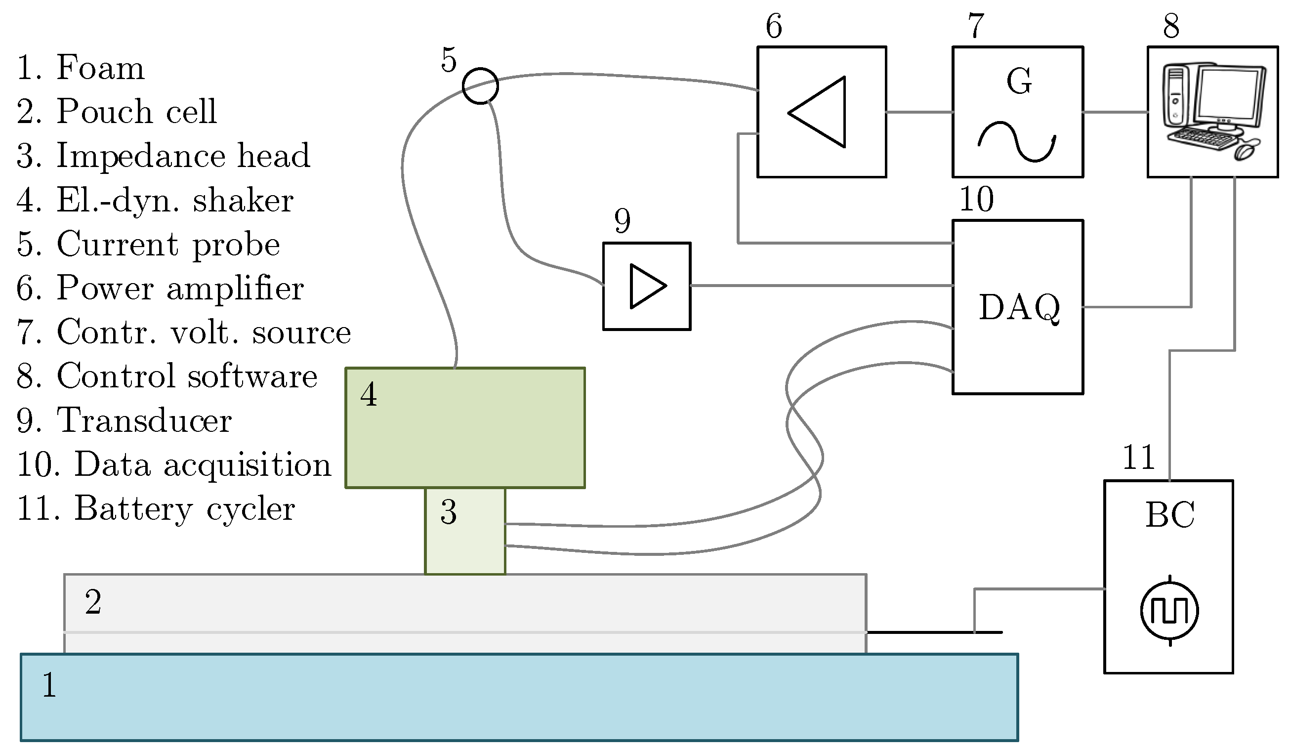
The set-up of the measurement (
Figure 1) consisted of a force generator type TMS 2002E miniature inertial shaker and an impedance head type 288D01, both from PCB Piezotronics, Inc. (Depew, NY, USA). The impedance head was screwed to the base of the shaker and mounted in the center of the cell with ultra-thin double-sided adhesive tape. To avoid external influences and to provide vibration isolation, the cell was placed on a foam padding with a natural frequency well below the first natural frequency of the cell (see also
Section 3).
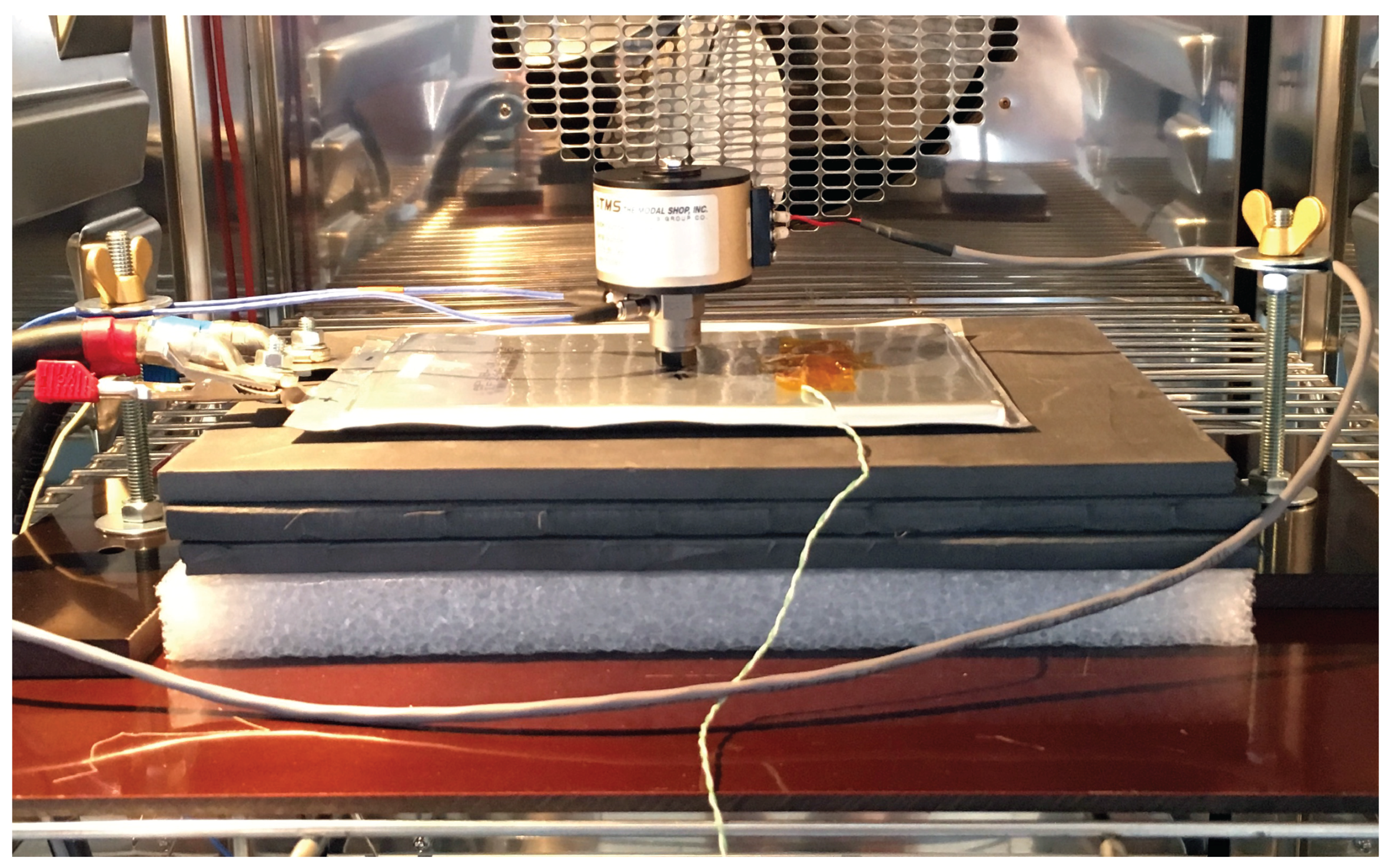
For excitation, the analogue output of a multifunction data acquisition board (DAQ) from National Instruments was used, and the signal was amplified with a power amplifier type 2706 from Brüel & Kjær (Nærum, Denmark). Data was acquired with the analogue inputs from the DAQ and signal conditioning amplifiers from Dewetron. Logged data includes the excitation voltage and current for the shaker as well as the force and the acceleration measured by the impedance head. The system was controlled with LabVIEW software (Version 2014, National Instruments, Austin, TX, USA), which generated the excitation signal and recorded the measured signals. The cycling and SOC adjustment was performed with self-developed battery cyclers. Each channel was calibrated, and the accuracy was 0.2% for the current and 0.1% for the voltage for measured value. During cycling and FRF measurement, the cells remained in the same position on the foam padding. The whole set-up was placed in a calibrated climatic chamber type VC4034 from Vötsch (Balingen, Germany) and remained unchanged during all tests on the same cell. The cell with the shaker, foam padding, and wiring placed in the climatic chamber can be seen in
Figure 2.
To identify possible distortions of the signal that may be a result of mechanical vibrations of the environmental test chamber or human-induced vibration in the laboratory, initial measurements were performed under idle conditions (no thermal control, no activity in the laboratory) before being performed under real conditions (with thermal control and activity in the laboratory). Influences were found to be insignificant and below measurement accuracy. To minimize the influence of the electrical connection on the set-up, the wiring and the connection was done with strain relief units, establishing a loose connection. During measurements, the shaker operated within its recommended specification with a linear sinusoidal sweep from 20 Hz to 3 kHz. The sweep duration was set to 5 s, and the sampling rate was 25 kHz. Each sweep was repeated 3 times, and an average response was calculated. For the sweep duration, 2 and 10 s were also tested. As the eigenfrequency of the measurement set-up was 18 Hz (see also below) and the measurement was performed with a linear sweep, it was important to minimize the influences of the eigenfrequency on the values of interest. The decay time of the signal could be calculated with
and
, with
D being the damping ratio. According to
Table 2, our lowest
D was about 0.1, assuming that the eigenfrequency has the same damping as the cell. This means that the 18 Hz frequency of the set-up impacts the 2 s measurement until a frequency of 1487.5 Hz, which includes the frequencies of interest. Thus, as a compromise between steady state conditions and measurement time, 5 s was chosen. The 18 Hz frequency was decayed by the time the shaker was excited at 297.5 Hz, which is already below our lowest frequencies of interest.
The data was transferred to the frequency domain using a fast Fourier transformation algorithm implemented in an Octave mathematical environment. Different forces were tested to find out the optimum for the given cell. Overly strong force lead to bumps during measurement, producing unwanted noise, while too weak a force leads to very low amplitudes, which are hard to measure. After several trials, an excitation of the given system, with a maximum force of 2.38 N and a root mean square force of 0.56 N, was determined as an optimum value. Applying such low force has the benefit of not changing any properties within the cell. Higher force or excitation over long periods are found to change the internal properties of the cell [
2,
19]; even when other work does not observe such an impact [
20], it should not be neglected.
For cycling and SOC adjustment, the cells were first cycled with two standard cycles according to the manufacturer’s specifications. This means a 0.5 C charge until 4.15 V with a constant voltage phase of 30 min and a discharge with 1 C down to 2.75 V, with C being the nominal capacity of the cell divided by 1 h. The capacity measured during the second discharge was then taken as the basis for further calculations. The measurement was performed at SOC levels 0, 25, 50, 75, and 100%. The FRF is determined starting from SOC 0% and charging to 100% and then again when discharging down to 0%. The SOC levels were set to a constant current charge and discharge, and a coulomb counting to the according value. A rest period of 90 min between SOC adjustment and measurement was set as the relaxation time.
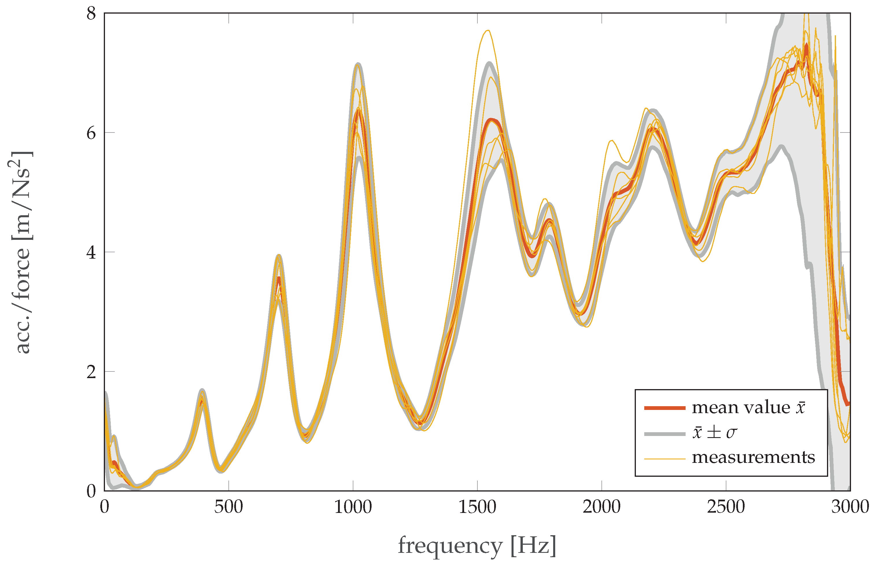
When each cell was measured, the mechanical set-up remained untouched; when the cells were swapped, it was necessary to remove both the electrical connections as well as the shaker itself. Slight misalignments during the new set-up can affect the measured FRF, either in terms of the amplitude or, in the worst case, the measured frequency peaks due to different modes being excited if the shaker is in a different position and the peaks are closely spaced. To evaluate these uncertainties a ‘blank’ measurement was performed; thus, the set-up was fully assembled and disassembled six times for the cycled cell at SOC 0%, each time followed by a measurement of the FRF. The uncertainties are shown in
Figure 3. It can be seen that the exact placement in the middle of the cell did lead to reproducible results regarding frequency stability for the regions of interest (≤1400 Hz), while the amplitudes show stronger variations, especially for the fourth eigenfrequency peak. This variation in measurement needs to be considered for the results achieved for different cell types when the set-up is changed in between.
To test the influence of the position of the shaker, a measurement was conducted with two additional impedance heads placed on the longitudinal and the lateral axes of the cell, 2 cm and 4 cm away from the center. With a higher distance from the center, a larger damping of the curve was measured. Additionally, especially for lower frequencies, a shift of the peaks in the frequency domain was detected. Accurate placement of the shaker and impedance head of the cell is thus crucial for the reproducibility of this method.
The eigenfrequency of the foam bedding under the plate during the experimental set-up (i.e., including the load of the cell) was determined using the decaying vibration response after impulse loading. It was measured to be 18 Hz, indicating that the eigenfrequency of the set-up was well below any eigenfrequency of the cell itself and thus had a negligible impact on the subsequent measurements.
As temperature and temperature distribution have a high impact on cell performance [
21], all measurements were taken under controlled environmental conditions. Cell temperature was measured with a thermocouple type K on the cells surface. When the surface reaches the test temperature ±1
C, 2 h are needed to reach thermal equilibrium before measurements are taken.
3. Results and Discussion
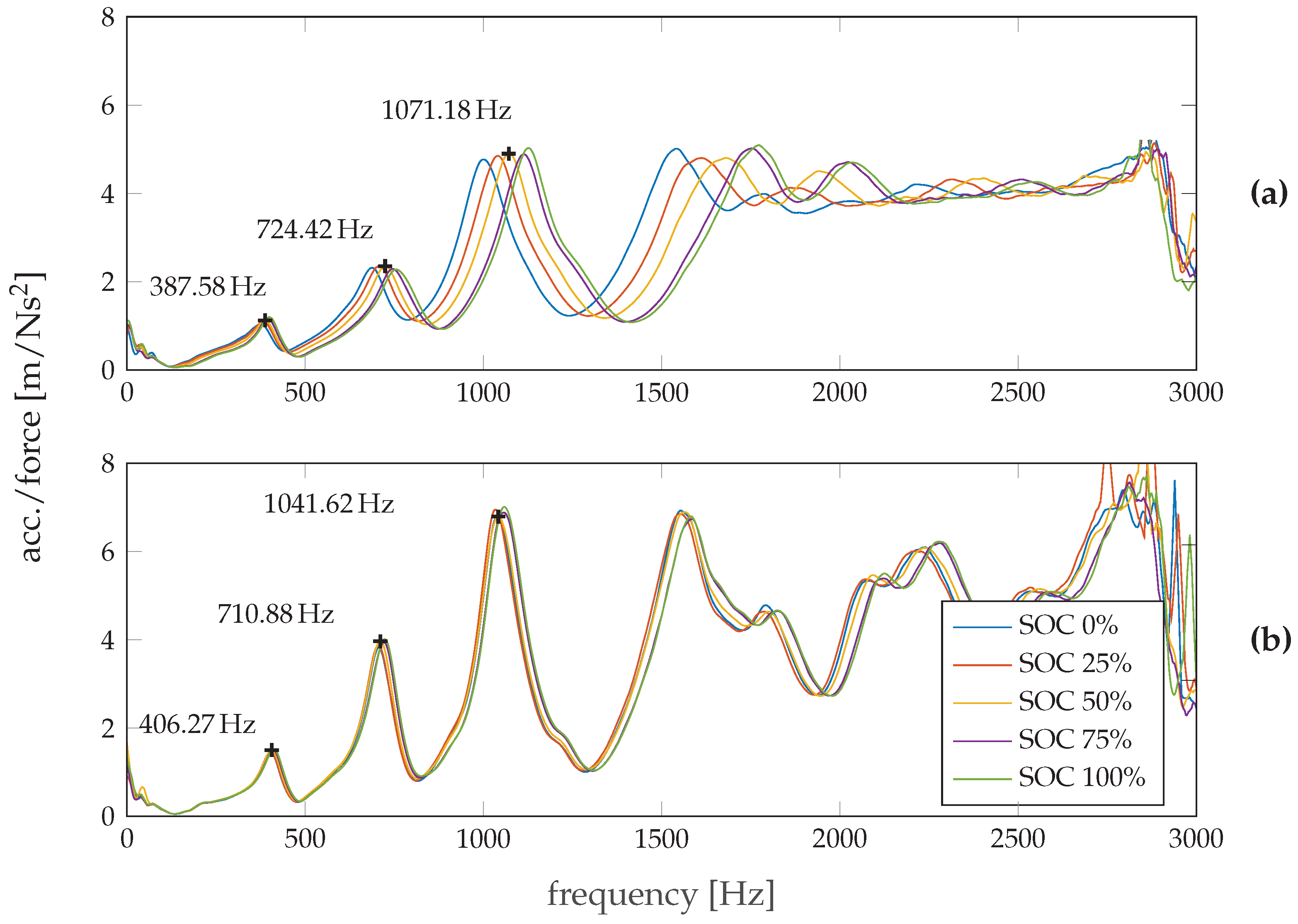
Figure 4a shows the smoothed FRF of the new cell for different SOC levels obtained during discharge at 25 °C. The full frequency range from 0 to 3000 Hz is displayed. The response at very low frequencies (≤100 Hz) resulted from the natural frequency of the foam material (see
Section 2) and thus is not further considered. At higher frequencies, three distinct peaks can be seen in the FRF for this cell type. All are within the range of 400–1400 Hz, while the magnitudes become greater at higher frequencies. Above 1600 Hz, there is a plateau with only minor changes and a steep decline close to 3000 Hz, marking the frequency limit of the shaker. The FRF curves from 100 Hz upwards show a shift towards higher frequencies with increasing SOC. Using the equation of harmonic motion
where
k defines the cell stiffness,
the natural frequency, and
m the mass of the cell, it can be seen that the cell becomes stiffer at higher SOC levels. Literature states that cells with a graphite-based anode show an increasing thickness during charging [
4,
22,
23], mainly as a result of the volume change caused by staging of the anode during lithium intercalation [
18], while the change in the cathode material is usually minor in comparison. Assuming the limited expansion within the pouch due to the surrounding materials, the observed increase in stiffness can be mainly linked to the staging process in the anode. The observation of higher stiffness at higher SOC levels is additionally supported by structural measurements on pure and on fully lithiated graphite (LiC
), which can be found in literature. In [
24], it is stated that LiC
has a significantly higher modulus of elasticity (
E). That stiffness is calculated by
, with
A being the surface area and
L being the length, indicates that the value of the stiffness of lithiated graphite is greater than that of pure graphite.
Figure 4b shows the FRF of the cycled cell. At first sight, the higher magnitude compared to the new cell is obvious. Considering potential measurement inaccuracies during rearrangement of the set-up (see
Figure 3 and
Section 2), not all of the changes in magnitude can be attributed to the decrease in SOH. The value for the 3rd eigenfrequency peak at approximately 1 kHz is 4.90 m/Ns
for the new cell and 6.79 m/Ns
for the cycled cell, with a standard deviation of 0.78 m/Ns
at this point, according to
Figure 3. However, it can be stated that the shifts between the peaks of the aged cell at different SOCs in comparison to the new cell are much smaller. According to Equation (
1), this indicates that, due to decreased reactivity, a cycled cell, though associated with inevitable degradation of the active materials, shows smaller changes in investigated mechanical characteristics with altering SOC. In other words, the stiffening is not so distinct with increasing SOC and, on average, the cycled cell appears to be less stiff than the new one. This is supposed to result from the irreversibly intercalated ions, the delamination, and the passivation films that formed a solid electrolyte interface, where the latter become more noticeable with every cycle [
25].
Furthermore, it can be seen that the peaks of the cycled cell are narrower than those of the new one. This suggests a decrease in the damping ratio
D of the cell with decreasing SOH. The damping ratio for each natural frequency can be approximated from
where
Q is defined as the Quality-Factor
where
is the natural frequency, and
is the frequency width between those points, which are half the maximum amplitude (full width at half maximum).
Table 2 contains the damping ratios calculated for the three peaks at all SOC levels for both the new and the cycled cell. It can be seen that the changes in the damping ratio of the cycled cell at different SOC levels are much smaller than those of the new cell, providing a further indicator for significantly reduced reactivity in the active materials.
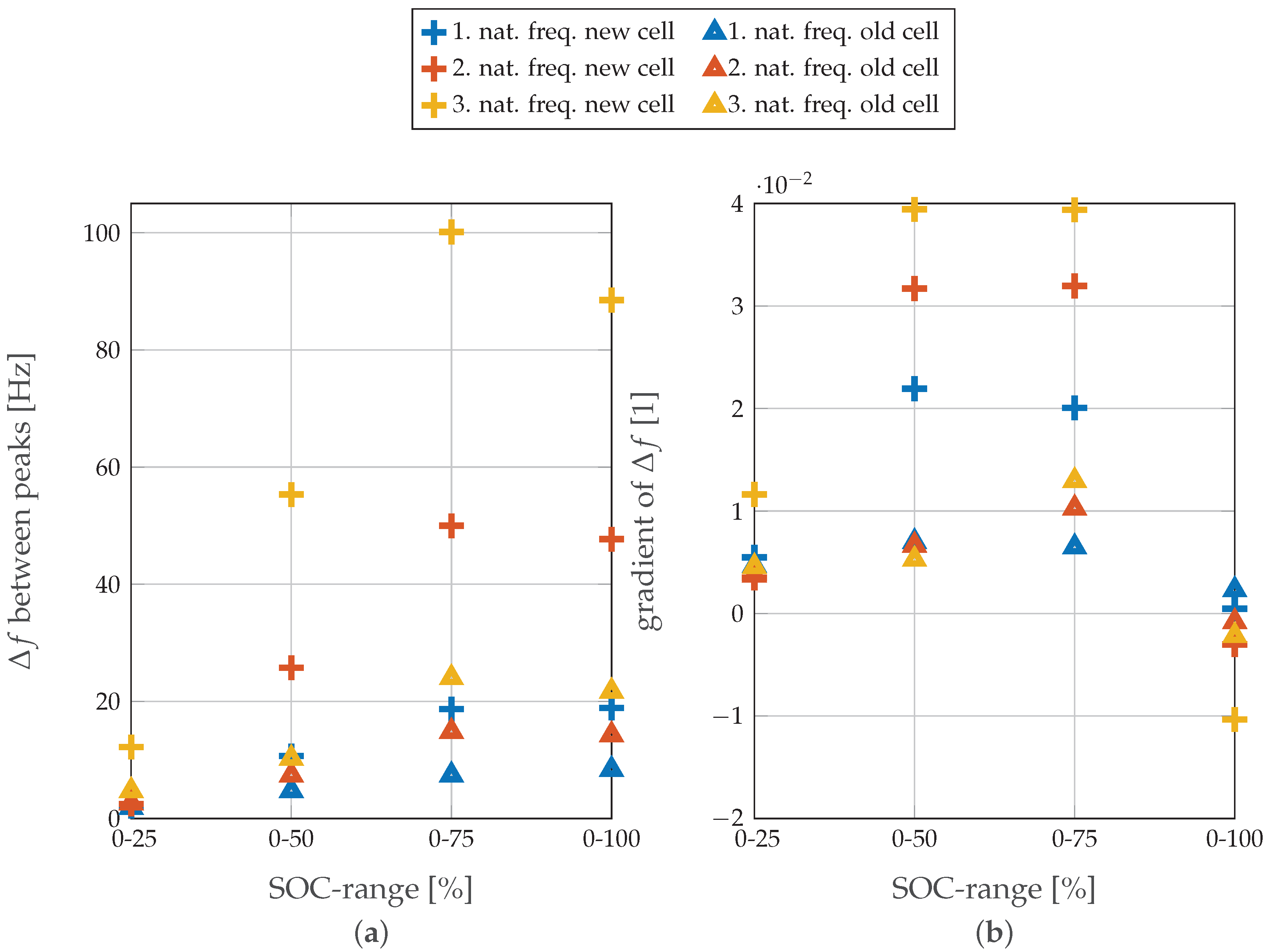
In
Figure 5a the absolute change in frequency
and in
Figure 5b the gradient of
for each SOC level is depicted for both cells in relation to SOC 0% at a temperature of 25
C. The markers represent the peak frequencies for the first three eigenfrequencies. It is noteworthy that, for the absolute change in frequency, the new cell shows substantial fluctuations compared to the cycled cell; furthermore, this behavior is strongly manifested at higher SOC levels. This again is a strong indicator of significantly reduced system reactivity, which directly affects the measured capacity (dropped to 74.5% of the initial value). Most likely this reduced reactivity results from the formation of various passivation films, especially the Solid Electrolyte Interface (SEI), delamination, micro-cracking, and irreversible intercalated ions [
25]. The figure also implies a trend in the peak shift for both cells towards higher frequencies up to SOC 75% and then decreases for SOC 100%. This has also been found in former work [
16]. The underlying process has yet to be identified and requires a denser dataset between SOC 75 and 100%. However, this ambiguity, at the moment, inhibits a distinct correlation of the SOC with the FRF over the entire SOC range, but this correlation is possible at a lower SOC. The gradient of
shows the change in frequency scaled by the peak frequency at SOC 0%. This confirms the findings that an aged cell can be easily distinguished from a new cell by charging or discharging it to a mid-range SOC of 50–75% and comparing the eigenfrequency peaks. Actually, determining the absolute SOC of a cell of unknown SOH is easier for new cells than for old ones, particularly at the aforementioned mid-range SOCs. The peaks of the eigenfrequency visible in
Figure 4 and the given bandwidth in
Figure 5 indicate that an SOC or SOH estimation can also be performed with a narrow frequency window. To estimate SOC and SOH using, for example, the third eigenfrequency, a window of 100 Hz around a center frequency of 1050 Hz is enough to detect all effects. This becomes practical for optimizing measurement time and saving equipment costs, especially considering a possible future application, for example, in an electric vehicle or a grid storage unit.
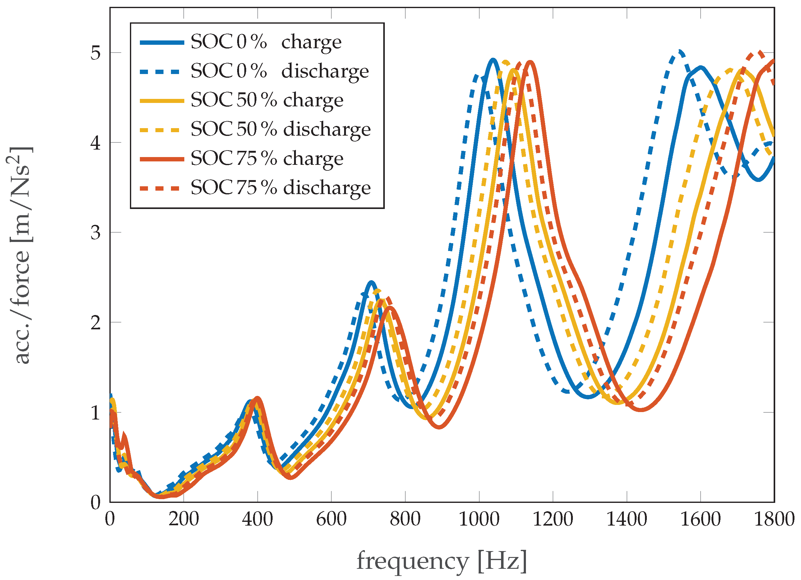
The FRF of the cell at a certain SOC level varies, depending on how the SOC is reached. This is most likely due to the hysteresis effects of anode swelling, which could be related to the cell’s charge or discharge history, or even the previous C-rate [
22].
Figure 6 shows the FRF for the new cell for charge and discharge at selected SOC levels. It can be seen that there is a small shift in both magnitude and frequency for each SOC between the values reached by charging and those reached by discharging the cell. In [
22], similar hysteresis behavior is found for thickness increases of an NMC/G cell and is identified as a result of the transformed intercalation structure during charge and discharge. The difference observed at SOC 0% originates in an altered discharging regime. While the initial SOC was reached with an uninterrupted discharge from SOC 100% down to 0%, the second value was reached by the stepwise discharge required for the measurement. Nevertheless, without existing prior knowledge about the system, this shift is not sufficient to allow for correlation of the frequency response directly to the SOC level.
The complete results obtained from the new and cycled cells imply that this method is appropriate for the indication of structural changes in the active materials caused by alterations in the state of the battery. It has to be underlined that, since the relevant frequency range is not very broad (no high frequency set up required), the implementation of this method into test benches should be relatively easy, and is necessary for potential new applications of LIBs in the near future. The number and position of the peaks are a result of the form factor of the cell or object under test. For modules or hard case cells, more peaks and different shapes are to be expected.
Often LIBs are exposed to sharp temperature variations with regard to their vast spectrum of application, so the effect of the temperature change on the FRF is also investigated. In this scenario, the new cell is tested at 0, 25, and 45 °C at every SOC. For the sake of legibility,
Figure 7 only shows two SOC values per temperature, but the other SOC levels exhibit similar behavior. It can be observed that the magnitude of the signal becomes greater with rising temperature, whereas the peaks shift to lower frequencies. Because the materials tend to soften at higher temperatures, their stiffness is reduced as they warm up, so natural frequencies are detected at lower values. Herewith, the influence of temperature becomes the dominating effect over frequency shifts due to changing SOC.
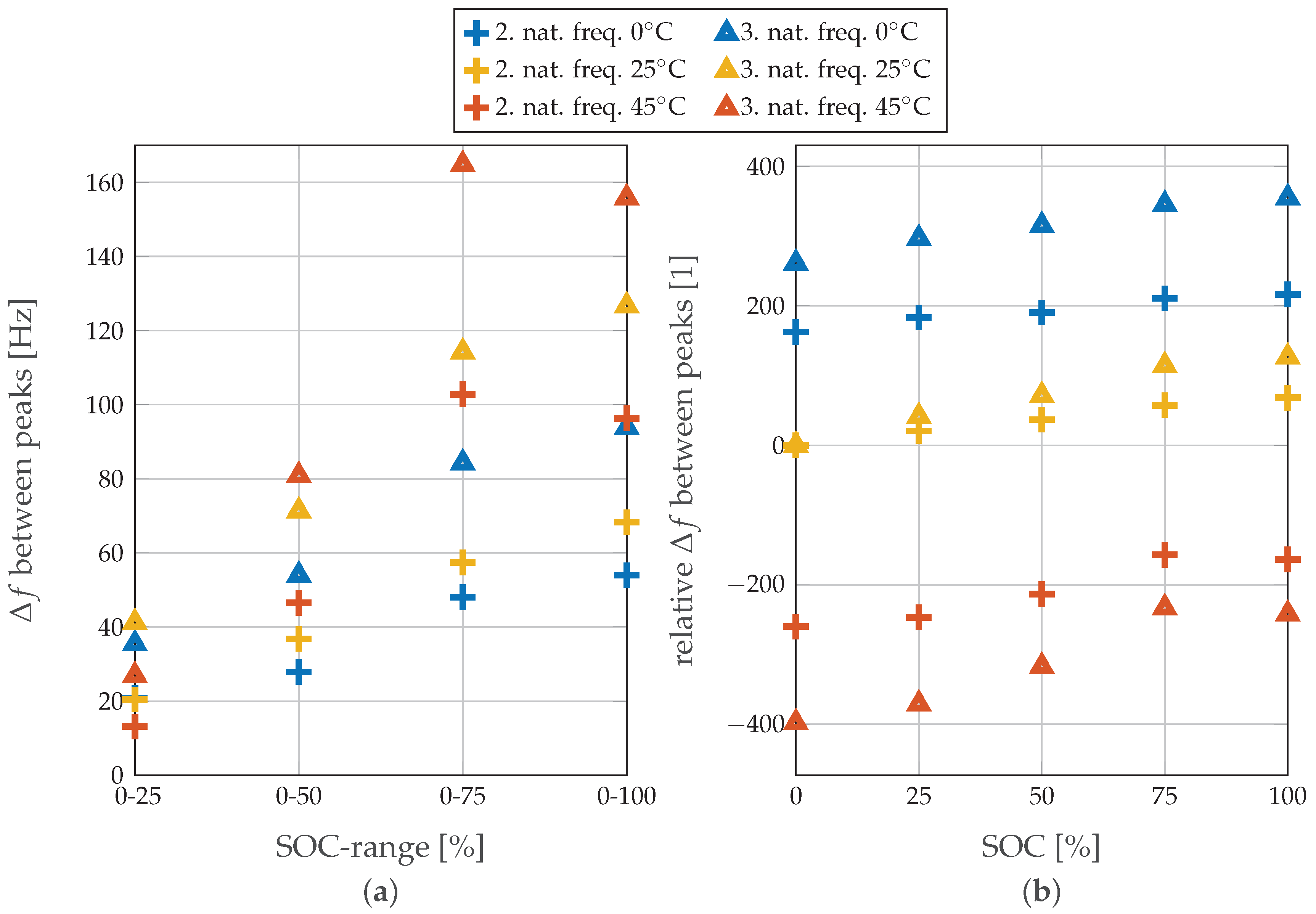
In
Figure 8, the natural frequencies of the system are presented. Their shifts indicate the changes in the cell´s mechanical properties. Because the first natural frequency shows an insignificant shift compared to the higher eigenfrequencies, the graph displays only the second and third natural frequencies for each SOC level relative to SOC 0% for all of the three chosen temperatures. A noticeable monotonic increase in all eigenfrequencies up to SOC 75% is detected at all temperature levels. For 0 and 25
C, this monotonic increase continues up to SOC 100%, while at 45
C for SOC 100% the frequency value is lower than the one measured at SOC 75%. In summary, at higher temperatures, the peak shifts are more pronounced, as expected, due to stimulated system reactivity with increased temperature. However, a noteworthy observation here is that, for SOC 25%, a greater change is observed at lower temperature values.
4. Conclusions and Outlook
In this work, the correlation between the SOC and the FRF at low-frequency mechanical excitation of an LIB was presented. The obtained results show visible and distinct changes in the FRF with varying SOC, and reproducibly confirm detectable shifts with sharp temperature variations for the particular case of 20 Ah commercial pouch cells manufactured with NMC-cathode and G-anode. Since the test setting is well-defined and repeatable, it is projected that a determination of the SOC becomes feasible when prior knowledge about the system is available, although it is not sufficiently practical at the present moment. Nevertheless, at a given temperature, the FRF measurements could become a method of choice in determining the absolute SOC of the cells at a given temperature.
Regarding the SOH, it was found that the pre-aged cell with a long cycling-life history tends to become softer and that the absolute changes in the FRF are smaller than for a new cell, which could be attributed additionally to internal cracking, de-lamination, or fracture. However, the influence of other parameters on the FRF was found to be stronger than the influence of the SOH itself, which confirms that prior system knowledge is a major requirement for determination. This method is suitable for monitoring changes of the mechanical parameters, which is very important during construction of battery systems, and highly relevant for the automotive sector [
15,
26,
27]. Therefore, the approach presented in this work could assist as a non-destructive method of collecting information about parameters of the battery cell such as damping and stiffness. The non-destructive aspect is particularly relevant because other mechanical tests may bring undesirable side reactions and are thus often performed only at lower SOC [
26,
27]. The measurement procedure validated with our experiments is based on the frequencies within the audible range (in this case, from 20 Hz to 3 kHz); therefore, in comparison to ultrasonic analysis, requirements to this test, both for excitation and measurements, are not very demanding.
As a future goal for investigations, the actual changes in the materials have to be investigated (which may include different physico-chemical methods, including destructive tests), and the correlation between measured FRF values and factual changes in materials structure with regard to diverse cell chemistries and geometries should be defined. Refining the repeatability when reassembling the set-up is still necessary. Since swelling of the battery casing is also often observed during and after battery operation, especially on hard case prismatic cells [
23], it is of utmost interest to consider this geometry type for modal analysis. For feasible future investigations, this would have a major impact on whole battery module systems.
