Simulation Modeling and Optimization of Uniflow Scavenging System Parameters on Opposed-Piston Two-Stroke Engines


School of Energy and Power Engineering, North University of China, Taiyuan 030051, China
*
Author to whom correspondence should be addressed.
Energies 2018, 11(4), 940; https://doi.org/10.3390/en11040940
Submission received: 31 January 2018
/
Revised: 9 April 2018
/
Accepted: 10 April 2018
/
Published: 16 April 2018
(This article belongs to the Special Issue Recent Advances in Internal Combustion Engines Operation and Emissions)
Abstract
:Based on the introduction of opposed-piston two-stroke (OP2S) gasoline direct injection (GDI) engines, the OP2S-GDI engine working principle and scavenging process were analyzed. GT-Power software was employed to model the working process based on the structural style and principle of OP2S-GDI engine. The tracer gas method and OP2S-GDI engine experiment were employed for model validation at full load of 6000 rpm. The OP2S-GDI engine scavenging system parameters were optimized, including intake port height stroke ratio, intake port circumference ratio, exhaust port height stroke ratio, exhaust port circumference ratio, and opposed-piston motion phase difference. At the same time, the effect of the port height stroke ratio and opposed-piston motion phase difference on effective compression ratio and expansion ratio were considered, and the indicated work was employed as the optimization objective. A three-level orthogonal experiment was applied in the calculation process to reduce the calculation work. The influence and correlation coefficient on the scavenging efficiency and delivery ratio were investigated by the orthogonal experiment analysis of intake and exhaust port height stroke ratio and circular utilization. The effect of the scavenging system parameters on delivery ratio, scavenging efficiency and indicated work were calculated to obtain the best parameters. The results show that intake port height stroke ratio is the main factor for the delivery ratio, while exhaust port height stroke ratio is the main factor to engine delivery ratio and scavenging efficiency.
1. Introduction
The opposed-piston two-stroke engine (OP2S) concept can be traced to the late 19th century in Europe, and subsequently developed in multiple countries for a wide variety of applications including aircraft, marine vehicles, and land vehicles [1,2,3]. Compared with conventional engines, opposed-piston two-stroke engines have some advantages, such as high power density, low heat transfer loss and mean piston velocity, and well balanced performance. However, the emission performance is worse because of the high machine oil consumption. In the recent years, with the advance in design technology, modern analytical tools, materials, and engineering methods, the emission problem is no longer limiting the successful design of a clean and efficient OP2S [4].
OP2S has again attracted intensive attention with the aim of improving the engine efficiency and emission performance [5,6,7,8,9]. Hofbauer [5] and Franke et al. [3] described the design and development of an opposed-piston opposed-cylinder engine (OPOC). It has only one crankshaft for two cylinders; all forces go to this crankshaft and not to the main bearings and the crankcase. This configuration also makes the engine inherently self-balanced and modular, to enable the offering of an engine with a wide power range. The engine has achieved 650 kW at 3800 rpm, and 1600 Nm at 2200 rpm. Its minimum specific fuel consumption ratio was 206 g/kW·h at 1600 Nm and its total engine displacement was 5.22 L. Hirsch et al. [6] developed an opposed-piston two-stroke diesel research engine to enable further development of this engine type for prime power in combat vehicles. The engine is reported achieve 645.5 Nm at 1400 rpm, because of its potential for high power density and low fuel consumption, and is a viable advanced engine alternative. Herold et al. [1] presented thermodynamic analysis by comparing a six-cylinder four-stroke engine, a hypothetical three-cylinder opposed-piston four-stroke engine, and a three-cylinder opposed-piston two-stroke engine. The results showed that, when evaluated over a representative engine speed/load operating map, the OP2S engine achieved 10.4% lower weighted-average specific fuel consumption than the four-stroke engine at the same boundary conditions while operating with lower peak pressure and temperature. Regner et al. [7] conducted an experiment on an opposed-piston two-stroke engine. A 15.5% fuel consumption improvement compared to a state-of-the-art 2010 medium-duty diesel engine at similar engine-out emissions levels was reported, and engine-out emission would be expected to achieve the stringent 2010 US heavy-duty emission standards. Naik et al. [4] optimized an opposed-piston two-stroke engine, presented for a 1200 rpm 8.8 bar IMEP operating condition with 53.5% indicated thermal efficiency—an exceptionally good number for a 1.6 L engine. Redon et al. [8] conducted an experiment researching an opposed-piston two-stroke engine; the results revealed that opposed-piston engine benefits high efficiency and low emissions. In fact, over 30% fuel economy improvement was observed when compared to an equivalent four-stroke diesel engine. Moreover, the engine can be used to meet 2025 light-truck CAFE fuel economy regulations.
Xinyan Wang et al. evaluated different scavenge port designs for a boosted uniflow scavenged direct injection gasoline engine by 3D computational fluid dynamics (CFD) simulations [9]. Several important design parameters, such as scavenge port number, axis inclination angle, swirl orientation angle, scavenge port opening timing, and scavenge port height, were investigated in detail under different engine speeds and intake pressures. Yan Zhang et al. investigated the effect of valve timing on the gas-exchange process and the subsequent combustion processes were investigated on a single-cylinder poppet-valve gasoline direct injection (GDI) engine running in two-stroke engine operation [10]. By individually varying intake and exhaust valve opening and closing the timing at a low load boundary, middle load boundary, and high load boundary of engine operation, Jun Ma et al. optimized the intake charge organization to optimize the two-stroke uniflow engine performance on vehicle application through building a 3D CFD model [11]. The scavenging process was investigated, and the intake port design details were improved. Gerhard Regner et al. have perfected the OP engine architecture, demonstrating substantial breakthroughs in combustion and thermal efficiency after more than 3300 h of dynamometer testing, which is also a good fit for other applications due to its high thermal efficiency, high specific power, and low heat rejection [12]. Enrico Mattarelli et al. researched the potential of the two-stroke concept for Range Extender engines. The scavenging is of the Loop type, without poppet valves, and with a four-storke-like lubrication system [13]. Krishna et al. researched the in-cylinder flow field analysis in a two-stroke engine under motoring conditions by particle image velocimetry. The engine parameters include engine speed, compression ratio, port area ratio and booster port orientation and the flow parameters [14]. Carlucci et al. compared the results of 3D simulations with those of 0D and 1D models by the two-stroke two banks uniflow engine model capability by describing the effect of several parameters on engine performance. They describe the effect of several parameters on engine performance and compared the results of 3D simulations with those of 0D and 1D models [15]. Carlucci et al. compared the performance of different supercharging systems in terms of power, fuel consumption, and their effect on trapping and scavenging efficiency at different altitudes by 1D model [16]. The validated 0D/1D model has been used to simulate the engine behavior with several varying design and operation engine parameters.
The OP2S-GDI engine uses uniflow scavenging and GDI technology to realize separation of the injection and scavenging processes. Referring to compression ignition engine theory, the initial swirl and tumble were generated by intake system. During the compression stroke, squish effects occur, which depend heavily on piston motion and combustion chamber structure [17,18,19]. However, in the OP2S, two pistons moving in one cylinder make in-cylinder gas motion quite different from the conventional two-stroke diesel engine. Furthermore, combustion chamber structure is also different, resulting in the squish effects near minimum volume center in the OP2S being different from the conventional two-stroke diesel engines. The OP (Opposed-Piston) arrangement has no cylinder head, and the fuel injectors must be installed in the cylinder liner, which may result in a different combustion compared to conventional two-stroke diesel engines. As a form of ranger-extender, a small generating set is used for online supplement energy, which has small displacement, high power density, and simple and compact structure. The OP2S-GDI engine has some advantages in being a pure electric vehicle extender, since it is simple and compact, and has high power density and good balance [20].
In this paper, the orthogonal experiment calculation of one-dimensional working process simulation was employed as the optimization method for scavenging system parameter optimization. The tracer gas method and OP2S-GDI engine experiment were employed for model validation at a full load of 6000 rpm. The OP2S-GDI engine scavenging system parameters were optimized.
2. Uniflow Scavenging System of OP2S-GDI Engine
2.1. OP2S-GDI Engine Configuration
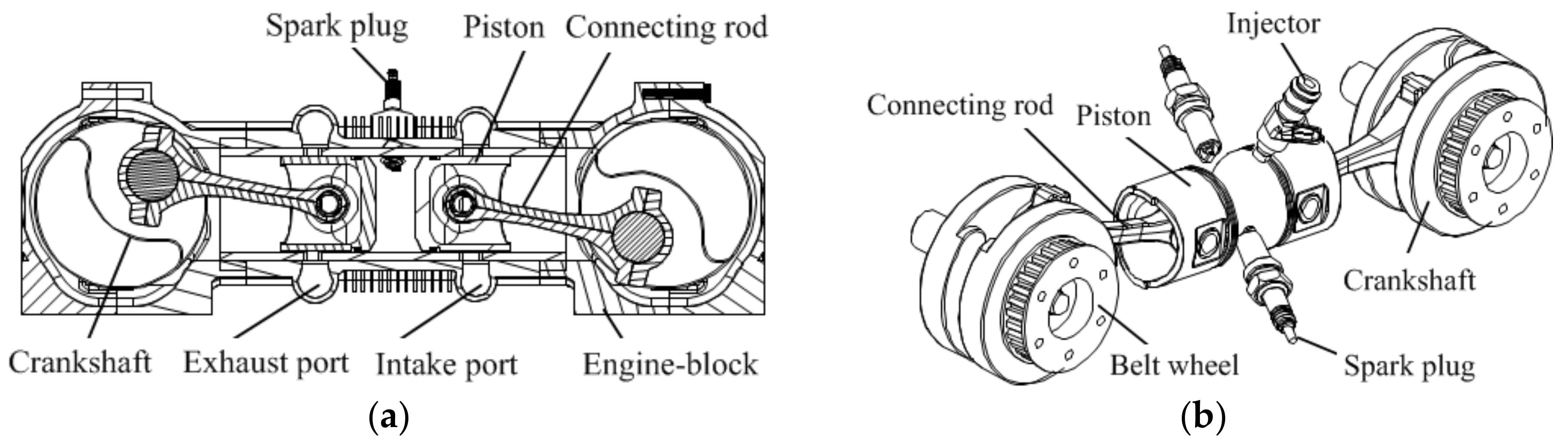
As shown in Figure 1, OP2S-GDI engine was equipped with the GDI system and “intake port-exhaust port” uniflow scavenging system, and its injector and spark plug were placed on a cylinder liner [21]. On both sides of the cylinder liner there were intake ports and exhaust ports. Intake ports are used to deliver fresh air into cylinder, and exhaust ports are used to deliver burnt gas from cylinder. The combustion chamber was formed when the opposed pistons moved to the closest position. The structure parameters are shown in Table 1.
2.2. Main Parameters of Uniflow Scavenging System
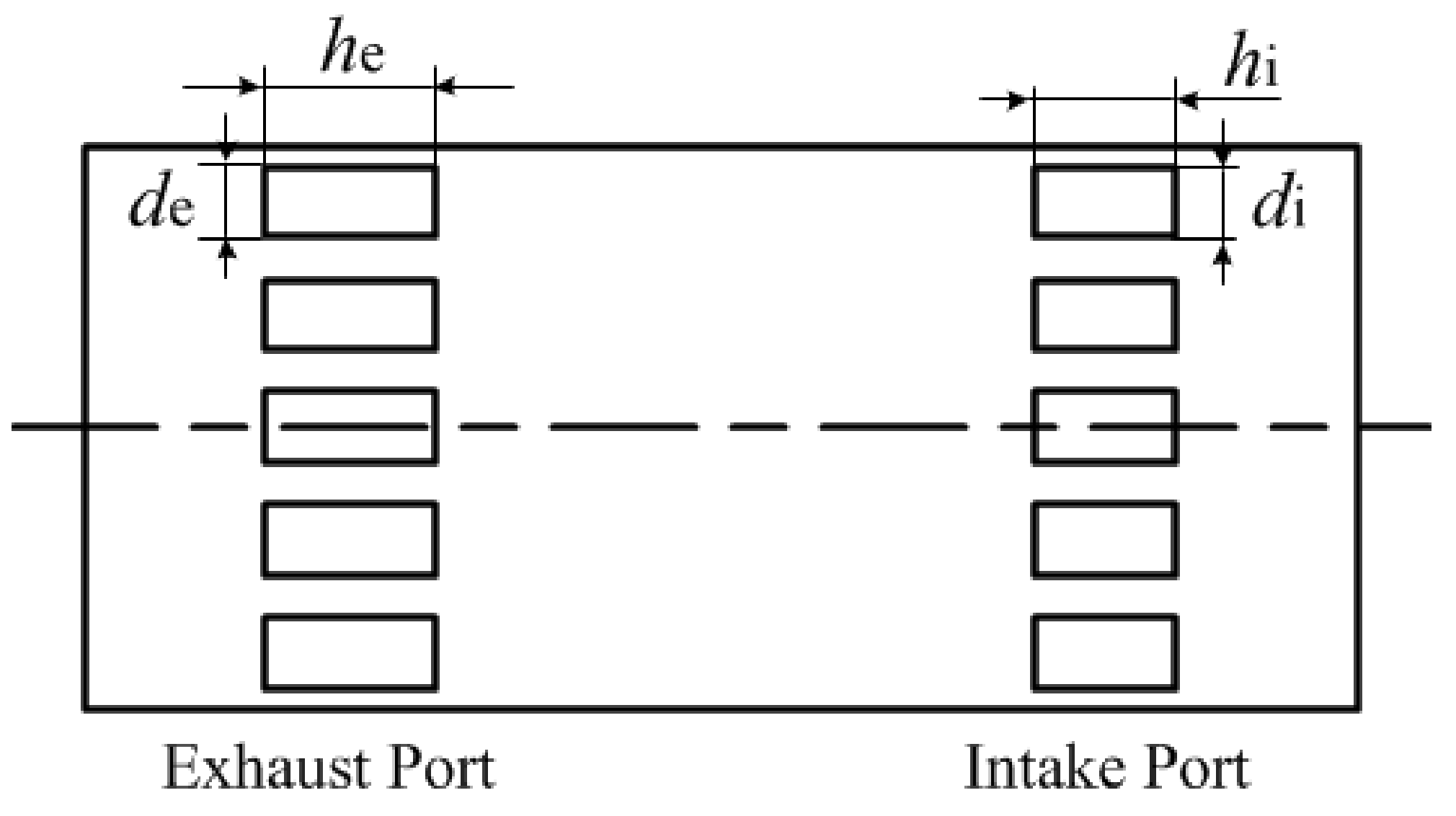
As shown in Figure 2, the scavenging system parameters include intake port height stroke ratio (hi), exhaust port height stroke ratio (he), intake port width (di) and exhaust port width (de). The port height stroke ratio (α) is defined as the ratio of port height stroke ratio and stroke length and the circumference ratio (β) is defined as the ratio of port width and cylinder circumferential length [21,22,23].
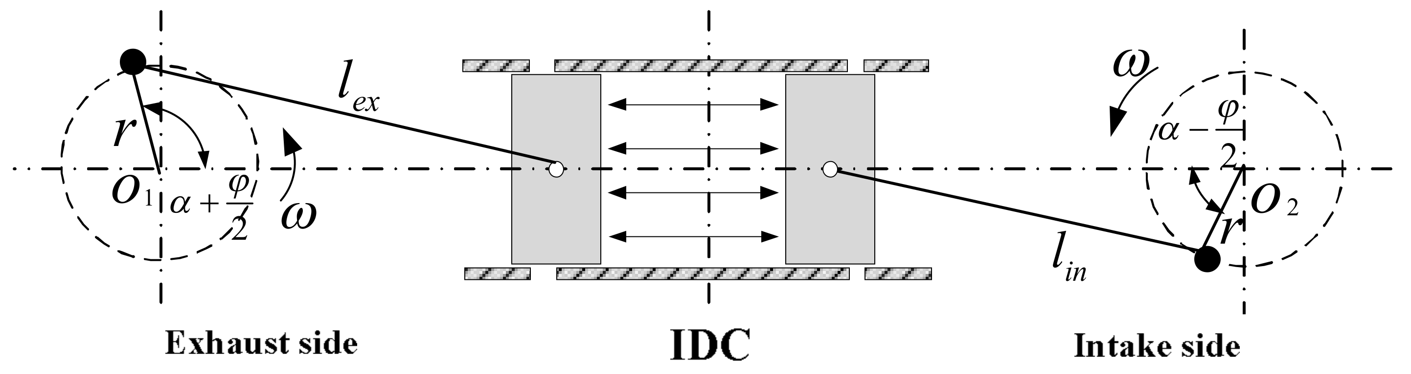
As shown in Figure 3, the opposed-piston motion phase difference (φ) is between the intake piston and exhaust piston motion phase difference. The port timing is asymmetric, in which the exhaust ports opening earlier than the intake ports; the exhaust ports also close earlier than the intake ports. Because of the φ, opposed pistons cannot arrive at each top dead center (TDC) simultaneously [20].
3. OP2S-GDI Engine Modeling
3.1. Working Process One-Dimensional Model
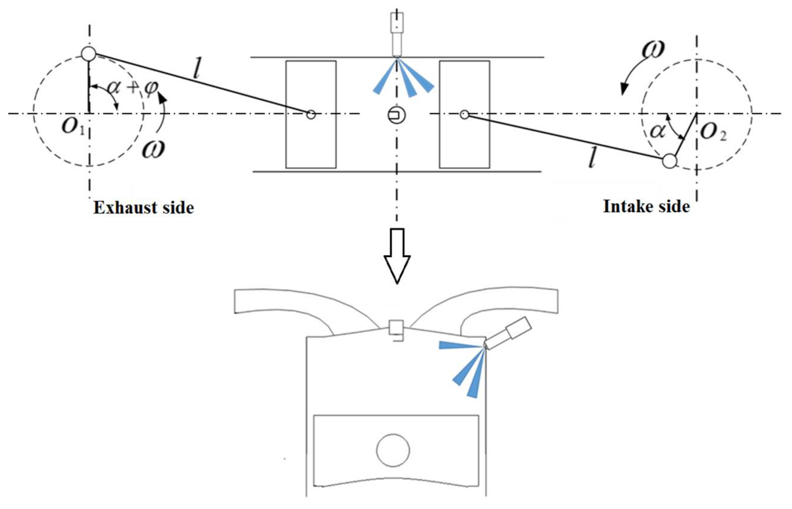
GT-Power software was employed to model for working process based on the structural style and principle of the OP2S-GDI engine. Because there was not a special model for opposed pistons in GT-Power software, the cylinder of OP2S-GDI engine should be equivalent to a single-piston cylinder, as shown in Figure 4. In the simulation model, the opposed-piston relative motion was equivalent to the single-piston motion.
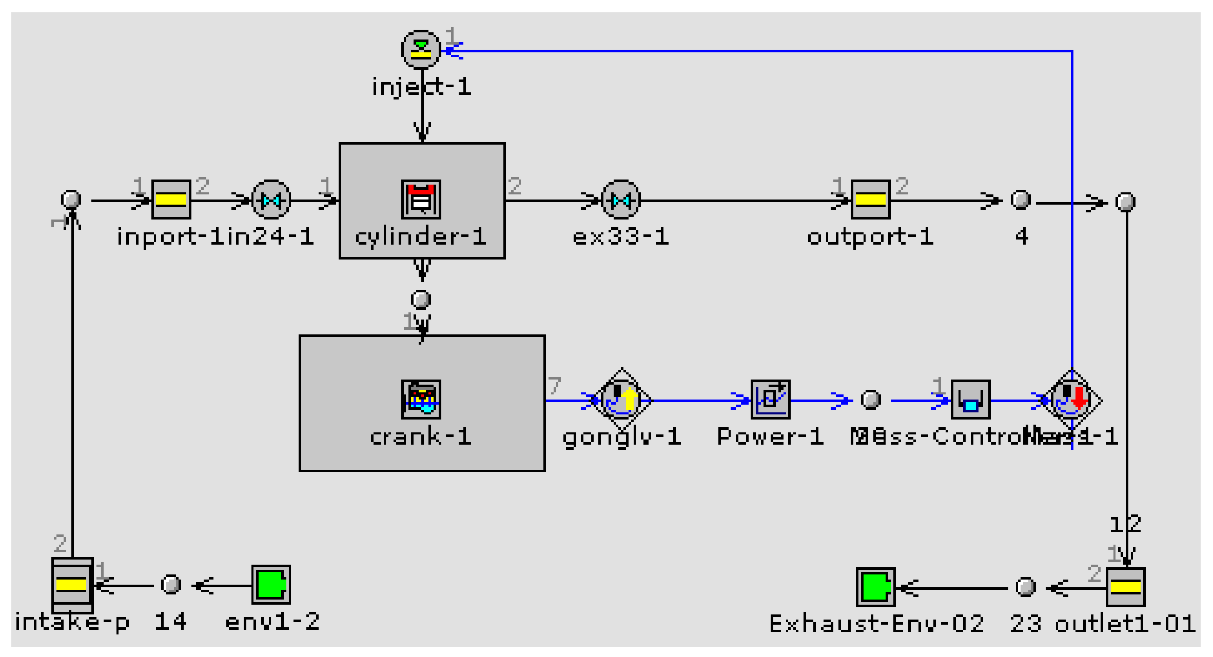
1D scavenging process is simulated by GT-Power. It is widely used in engine design because of its flexibility [24,25]. The detailed model is shown in Figure 5. In the GT-Power model, the “Eng Cyl Comb SI Turb” quasi-dimensional model and Woschni model were employed to describe combustion and heat transfer respectively [26]. This software solves 1D time dependent equations predicting the mass flux in intake and exhaust systems; a 0D approach is used to calculate the combustion development, in-cylinder pressure, the thermal exchanges, and the indicated work into the cylinders. Pressure losses, due to three-dimensional effects in particular zones of the engine, such as intake ports and exhaust ports, were considered through appropriate discharge coefficients, defined as the ratio between effective and geometric flow areas.
Based on the hypothesis of one-dimensional isentropic flow, the fluid flow condition of the free exhaust process can be written as the supercritical condition:
The fluid flow condition of scavenging process can be written as the subcritical condition:
where Cv is intake or exhaust port flow coefficient, n is engine speed, ps is inlet pressure, and pz is outlet pressure. For the exhaust ports, ps is in-cylinder pressure and pz is exhaust chamber pressure; for the intake ports, ps is intake chamber pressure and pz is in-cylinder pressure. Fs is area of intake or exhaust port in different crank angle, g is gravitational acceleration, k is adiabatic exponent, R is gas constant, T is gas temperature.
Delivery ratio, trapping efficiency, and scavenging efficiency were usually employed as evaluation indexes on the two-stroke scavenging system [18].
The delivery ratio:
The reference mass is defined as displaced volume × ambient air (or mixture). Ambient air (or mixture) density is determined at atmospheric conditions or at intake conditions.
The trapping efficiency:
The trapping efficiency indicates what fraction of the air (or mixture) supplied to the cylinder is retained in the cylinder.
The scavenging efficiency:
Uniflow scavenging process is assumed to be completed in three models: perfect displacement model, perfect mixing model and short circuit model.
For the perfect displacement model, trapping and scavenging efficiency vary with delivery ratio as follows:
For the perfect mixing model, trapping and scavenging efficiency vary with delivery ratio as follows:
The short circuit model is the direct flow of fresh mixture through the cylinder into the exhaust without entraining burned gases. There is no simple model for this process.
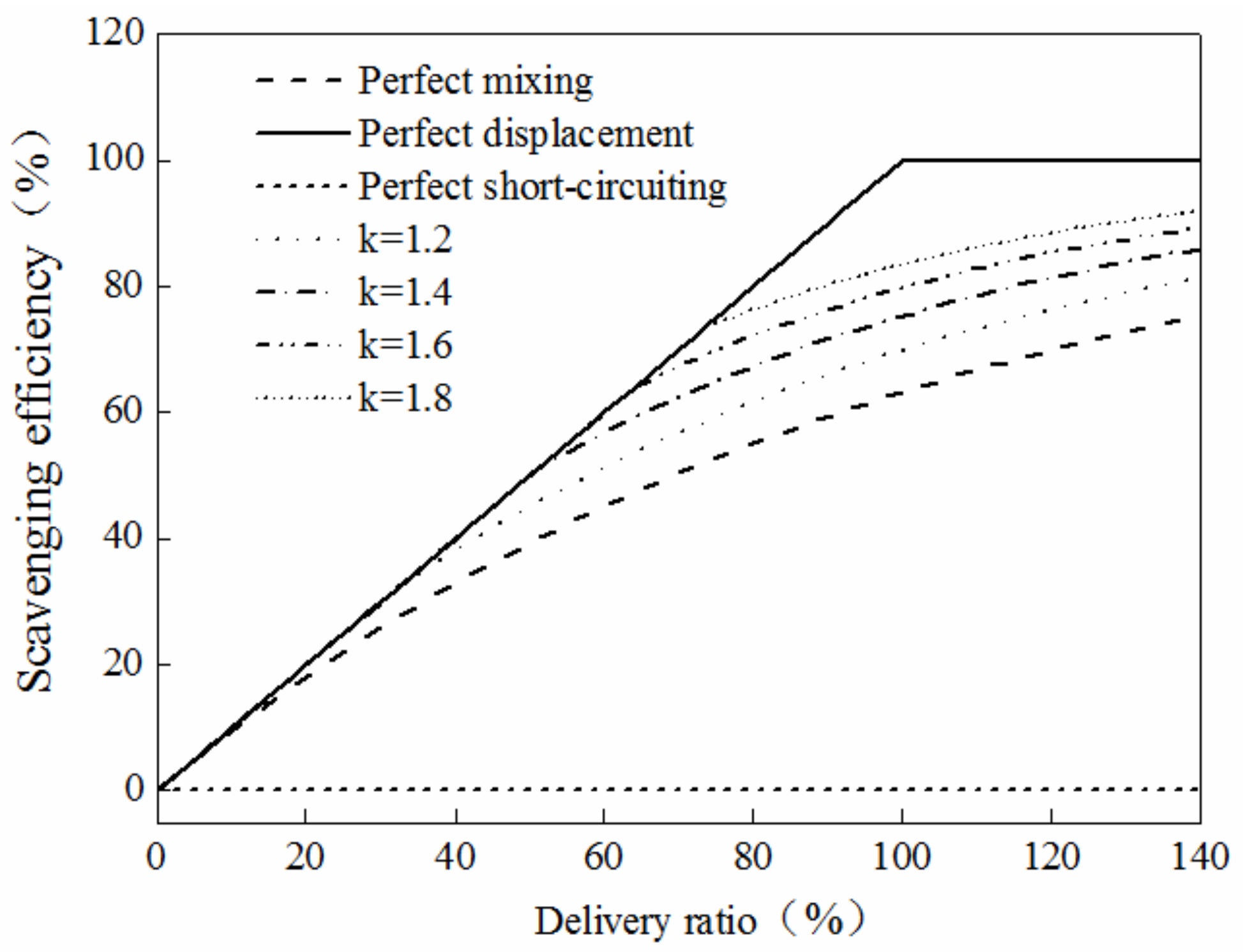
In practice, the scavenging process includes multiple scavenging models, giving a relation for scavenging efficiency:
where k is the scavenging model index, l0c is the demarcation point between perfect scavenging and rich exhaust scavenging.
For different k, the relationship between scavenging efficiency and delivery ratio was different, as shown in Figure 6. With the increase of k, the scavenging process was close to the perfect displacement model. When k was 1, the scavenging process was the perfect mixing model.
3.2. Model Validation
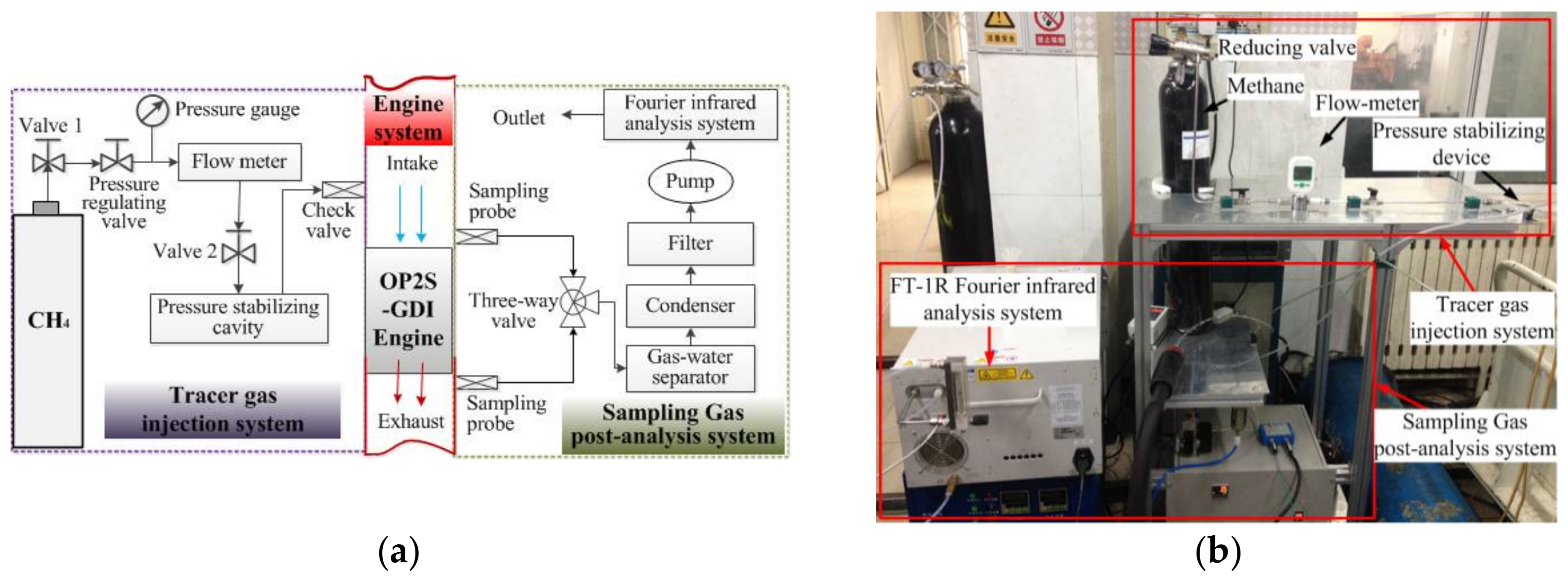
The tracer gas method was selected as the simplest method to measure the scavenging performance of the OP2S-GDI engine. As described in reference [2], the engine may be idealized as a steady-flow system. This method is based on the use of small quantities of a gas which are assumed to burn completely at combustion temperature but not to burn at temperatures below those prevailing in the cylinder when the exhaust ports open. Figure 7a presents the test schematic of scavenging efficiency using tracer gas method. It consists of three parts: tracer gas injection system, sampling, and analysis system and OP2S-GDI engine. As shown in Figure 7b, tracer gas methane is injected into the intake manifold for homogeneous mixing. The experiment utilizes reducing valve, flow-meter and pressure-stabilizing device for monitoring and controlling gas overflow.
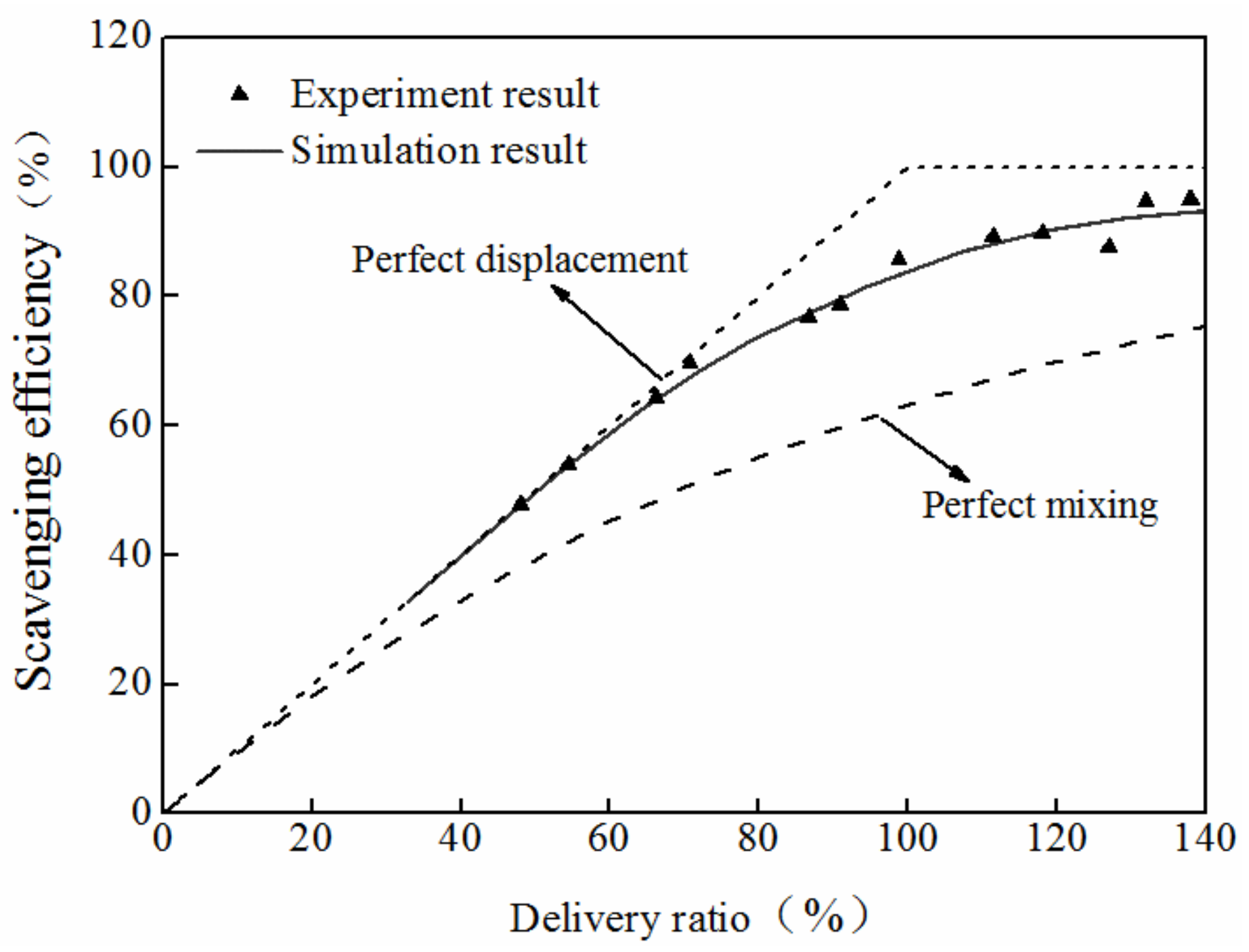
Figure 8 shows a gradual increase in scavenging efficiency as delivery ratio grows for simulation and experiment results. A simulation running at a full load of 6000 rpm is performed and a series of comparison validations of the one-dimensional in-cylinder scavenging process and tracer gas experiments were conducted. When k was 1.87, the scavenging process was located between of the perfect displacement model and perfect mixing model, and it was closer to the perfect displacement model [27,28].
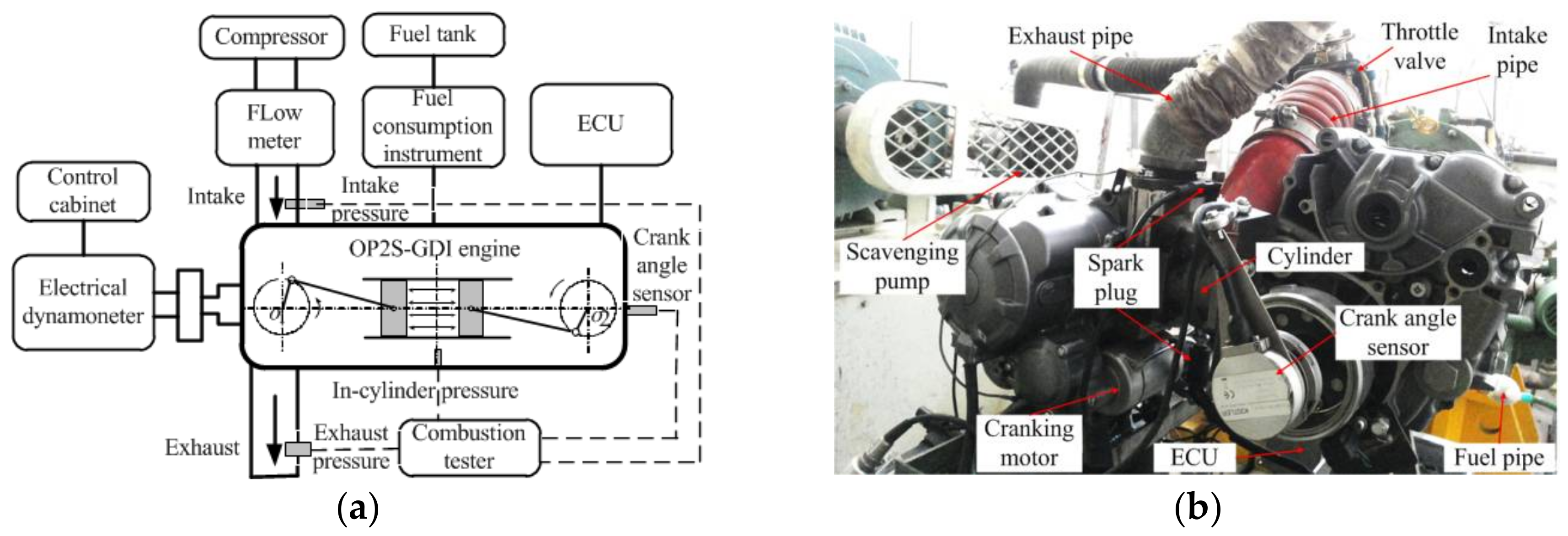
The OP2S-GDI engine test bench is shown in Figure 9 [29,30]. The control system uses Ecotrons NA2T1C250cc, as a supporting platform. It can control fuel consumption and use Pro CAL software for programming to achieve injection timing, fuel injection quantity, common rail pressure, and other parameters. In this experiment, the OP2S-GDI engine was coupled with an electrical dynamometer (CW25) to provide load. The rated absorption power is 25 kW, the maximum working speed is 10,000 r/min, and the torque measurement accuracy is ±0.2~0.3%FS, and the accuracy of the rotational speed is ±1 r/min. A water-cooled cylinder pressure transducer (Kistler model 6056A, Kistler Instrumente AG, Winterthur, Switzerland) was mounted on the cylinder line to measure the in-cylinder pressure. The in-cylinder pressure data of 50 engine cycles were collected with a resolution of 0.25 °CA. For in-cylinder pressure measurement by Kistler 6056A cylinder pressure sensor, the measuring range is 0~25 MPa, temperature range is −50~400 °C, test frequency is 130 kHz, testing sensitivity drift value is less than ±1%. Crankshaft position was obtained using a crank angle sensor to determine in-cylinder pressure as a function of crank angle. The crankshaft position signal is measured by a Kistler 2614B unit and its sampling precision is 0.2 °CA. Fuel consumption was determined by weighing the fuel used for a period of time on an electronic scale.
Table 2 shows the operating conditions of the analyzed case for the OP2S-GDI engine.
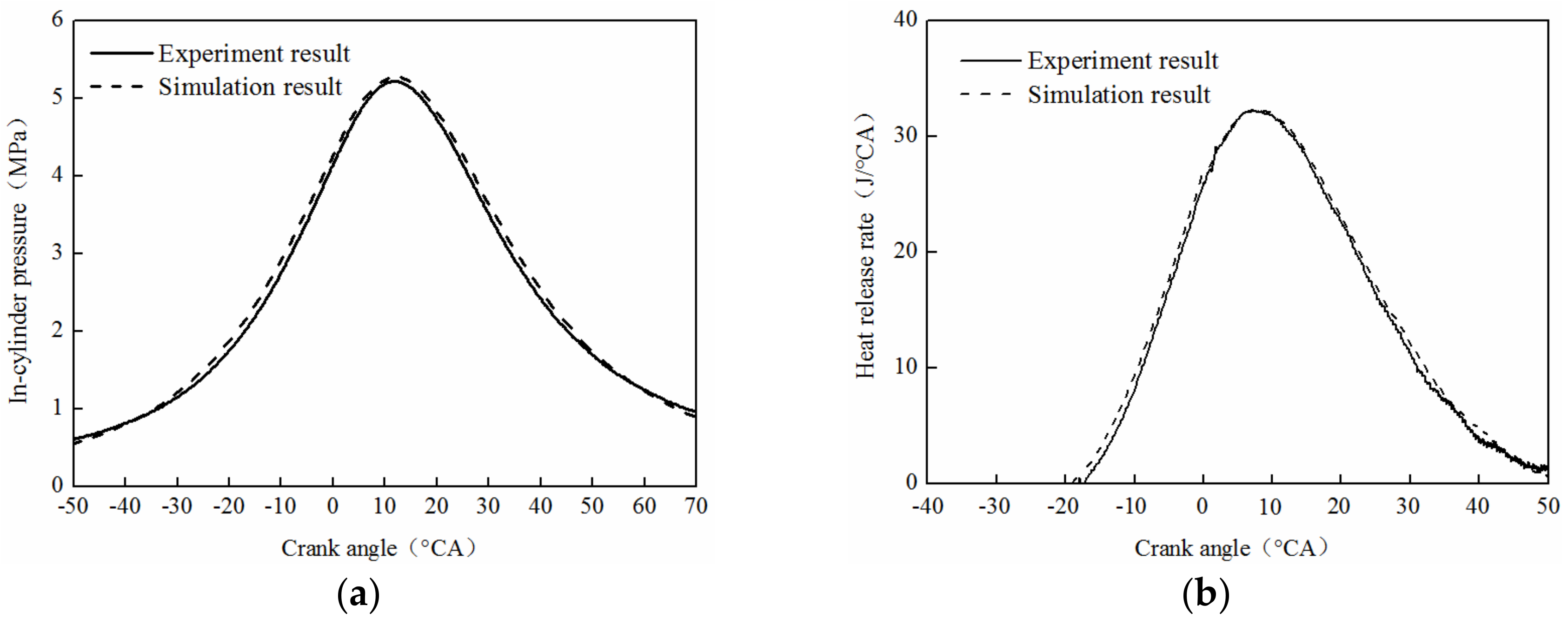
Figure 10 shows the comparison of simulation and experimental results for cylinder pressure and heat release rate. The simulation and experimental results were in good consistency and verified the correctness of working process simulation model equivalent, the scavenging model index, combustion, and heat transfer model. For the simulation result, the whole was greater than the experiment result and its error was less than 5%.
4. Parameter Optimization of Uniflow Scavenging System
4.1. Orthogonal Optimization for Port Parameters
The orthogonal experimental method was used to investigate the influence and correlation coefficient on the scavenging efficiency and delivery ratio about the port height stroke ratio and port circumference ratio [31]. The port height stroke ratio and port circumference ratio were determined based on orthogonal experimental design and working process simulation. The remarkable affecting factors of the scavenging process were accurately found through only a few calculations.
This research includes the following factors: intake port height stroke ratio (αi), exhaust port height stroke ratio (αe), intake port circumference ratio (βi) and exhaust port circumference ratio (βe). An orthogonal experiment is employed as an optimizer tool. There are three levels and four factors in the calculation projection. Interactions between A and C, and B and D will be considered, so L9 (34) is employed in this calculation. In the condition of a full load at 6000 rpm, the calculation case is shown in Table 3.
The order and contribution rate of every experiment factor on the target index is determined by means of range analysis. The difference between the maximum and minimum value in a set of data is called the range of this set of data, which reflects the fluctuation of this set of data. Based on Table 3, the value of I, II and III can be obtained by summing for index values of the same level at column including each factors, and the range value of this factor can be calculated to determine the primary and secondary order of each factor, which is shown in Table 4.
For the delivery ratio, the exhaust port height stroke ratio (B) is the major factor, which takes 0.167 as the optimal value because the range value of delivery ratio is maximized. As for the exhaust port circumference ratio (D), the secondary factor of delivery ratio takes 0.75 as the optimal value. Meanwhile, the secondary factors of delivery ratio, intake port height stroke ratio (A) and the intake port circumference ratio (C), take 0.121 and 0.75 as the optimal value, respectively. Through range analysis, the effect order of various factors on the experimental targets delivery ratio is B > A > D > C. Therefore, the optimal solution should be A1B3C1D3, which is close to the No. 3.
For scavenging efficiency, the intake port height stroke ratio (A) is the major factor, which takes 0.121 as the optimal value because the range value of scavenging efficiency is maximized. The intake port circumference ratio (C) is secondary factor, and the optimal value is 0.75. The exhaust port circumference ratio (D) is secondary factor. The best exhaust port circumference ratio is 0.75. The best intake port circumference ratio (C) is 0.75 and it has minimal effects on the scavenging efficiency. The effect order of various factors on the experimental targets scavenging efficiency is A > D > B > C. Therefore, the optimal solution should be A3B3C3D3, which is close to the No. 8.
The intuitionistic analysis of data cannot find out which parameters have significant influence on the index, but the analysis of variance can solve this problem. By range analysis, the influence of the intake port circumference ratio (C) on the delivery ratio and scavenging efficiency is relatively small compared with the other three factors, so it is not considered. Table 5 shows that the intake port height stroke ratio (A) and the exhaust port height stroke ratio (B) have a significant influence on the delivery ratio and scavenging efficiency.
Correlation analysis refers to the analysis of two or more variable elements with correlation, to measure the correlation degree of two variables, which confirmed the sensitivity factor through the analysis to data pertinence. The method of correlation analysis is employed to evaluate the correlation between the key parameter and the evaluation index of the scavenging process.
Table 6 shows the correlation coefficients of different scavenging system parameters for delivery ratio and scavenging efficiency.
The correlation coefficient of the delivery ratio and the exhaust port height stroke ratio (B) is 0.997, which is the strongest correlation and the correlation coefficient is the largest, so the exhaust port height stroke ratio (B) can be effectively meet the requirements of delivery ratio. The correlation coefficient of delivery ratio and intake port height stroke ratio (A) is 0.988, which is slightly lower than the exhaust port height stroke ratio (B). Intake and exhaust port circumference ratio (C and D) have relatively little influence on the delivery ratio, so the design of intake and exhaust height should be given priority for raising the delivery ratio.
The correlation coefficient of scavenging efficiency and intake port height stroke ratio (A) is 0.892, which is the strongest correlation and the correlation coefficient is the largest. Therefore, the increase of intake port height stroke ratio (A) can maximize the scavenging efficiency. The correlation coefficient of scavenging efficiency and exhaust port height stroke ratio (B), and intake and exhaust port circumference ratio (C and D) are the moderate correlation, relative to the intake height (A). This should be taken into consideration when improving the scavenging efficiency.
4.2. Optimization of Piston Motion Phase Difference
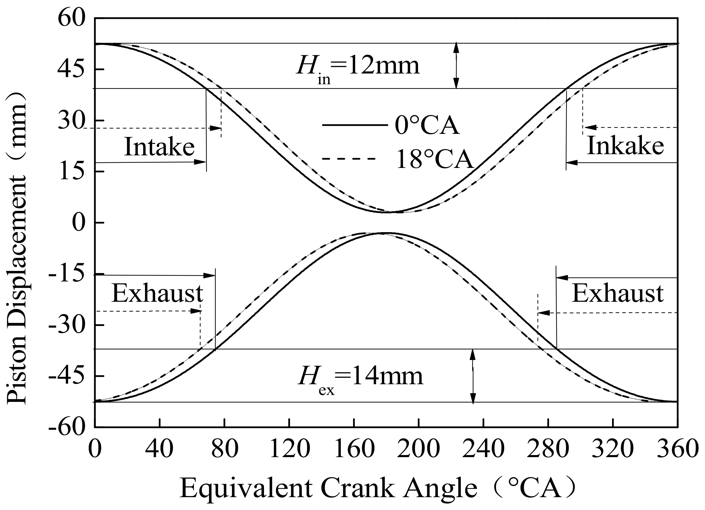
Figure 11 shows the phase difference is the only factor that influences engine scavenging timing when intake and exhaust port structure and piston movement rules are certain. With the phase difference varying from 0 °CA to 18 °°CA, the increase of phase difference can enlarge the asymmetry degree of intake and exhaust piston; meanwhile, the opening and closing of the exhaust port is advanced and the opening and closing of intake port is delayed.
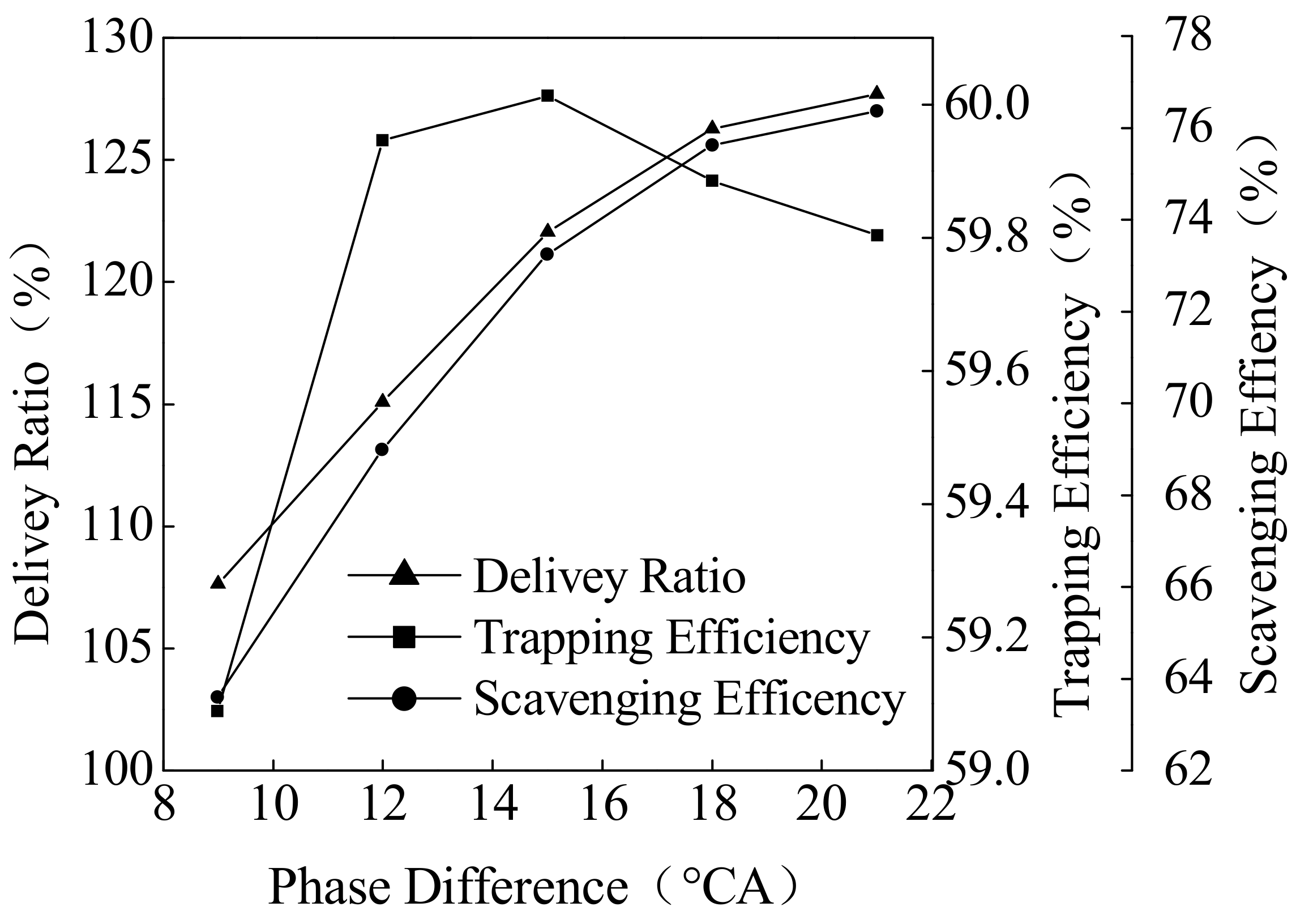
For the OP2S engine uniflow scavenging, perfect scavenging is assumed as no mixing of intake air with residuals occurs, and perfect mixing is assumed as all incoming fresh charge mixes instantly with the entire in-cylinder mass. To increase scavenging efficiency, delivery ratio is greater than 1. Figure 12 shows the increase of piston motion phase difference, the delivery ratio and scavenging efficiency increases gradually, the trapping efficiency will increase first and then decrease and is maximized at 15 °CA piston motion phase difference. When the intake port is opening, the lower the cylinder pressure, the more beneficial it is to intake. However, when the cylinder pressure is low enough, it is disadvantageous to the intake trapping. Therefore, the trapping efficiency begins to decrease when piston motion phase difference is larger than 15 °CA. Meanwhile, with the increase of intake port delay angle, the delivery ratio and scavenging efficiency is increased correspondingly.
OP2S engine performance was affected by piston dynamic directly and the piston’s opposite velocity was decreased with the piston motion phase increased. With the increase of piston motion phase difference, the scavenging efficiency and the flame development and rapid burning duration increased gradually; the indicated work would increase first and decrease then and shows its maximum at 15 °CA of opposed piston motion phase difference. When opposed piston motion phase difference was too small, the scavenging efficiency was low and the residual exhaust gas coefficient in cylinder was high, which does not favor the organization of the combustion process. If the relative velocity of the opposed piston was too fast, the cylinder working volume change rate near the inner dead center was bigger, and in-cylinder pressure and temperature dropped rapidly. The 15 °CA of opposed piston motion phase difference could improve the scavenging and combustion process effectively.
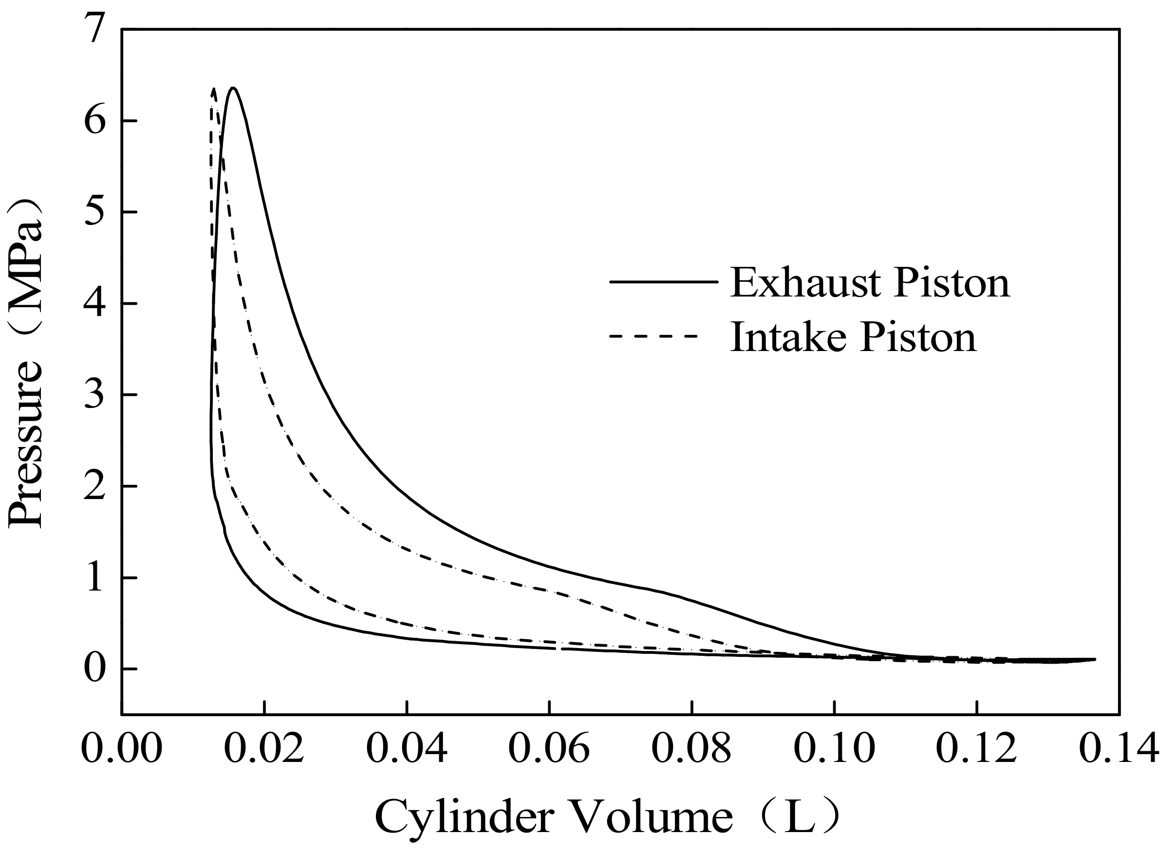
In the case of the same in-cylinder pressure, non-synchronized opposed-piston motion leads to the difference in the optimal burning TDC and heat-power conversion for two pistons. The indicated work of the opposed-piston at 15 °CA piston motion phase difference is shown in Figure 13. Because the exhaust piston motion is earlier than the intake piston motion, the indicated work of the exhaust piston is greater than the intake piston.
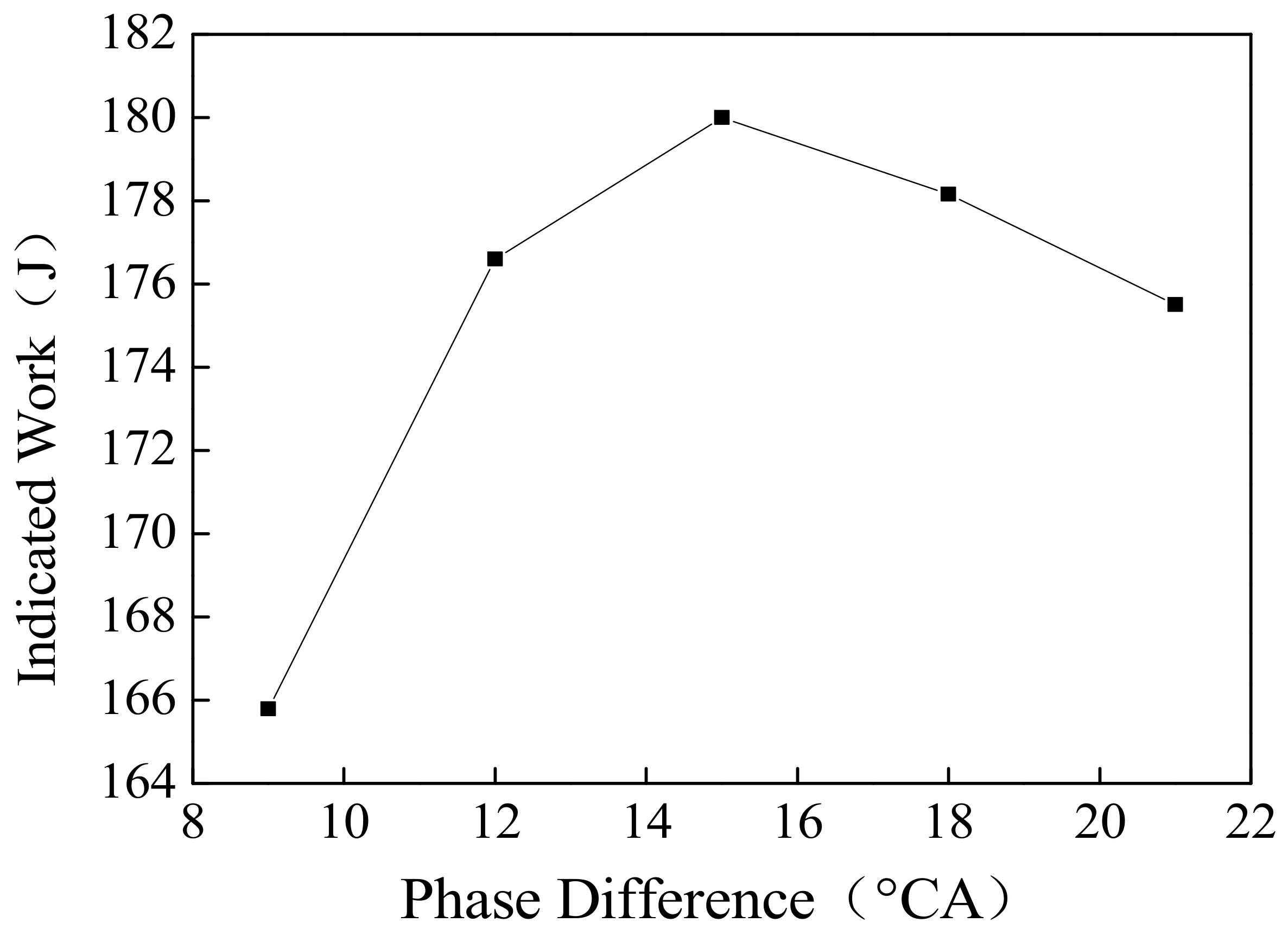
Figure 14 shows with the increase of piston motion phase difference, the cycle-indicated work increases first and then decreases. The indicated work is maximized when phase difference is 15 °CA. With the increase of piston motion phase difference, the in-cylinder scavenging efficiency is increased, but the compression ratio is decreased.
5. Conclusions
The OP2S-GDI engine working process simulation model was established based on GT-Power software. The tracer gas method and the OP2S-GDI engine experiment were employed for model validation. Effects of different scavenging parameters on delivery ratio, trapping efficiency, scavenging efficiency and engine performance were studied; orthogonal experiments were employed in the calculation process. The results of this analysis indicate that:
- (1)
- The influence order of different scavenging system parameters on the delivery ratio is exhaust port height stroke ratio (B) > intake port height stroke ratio (A) > exhaust port circumference ratio (D) > intake port circumference ratio (C). The correlation coefficient of the delivery ratio and the exhaust port height stroke ratio (B) is 0.997 and the correlation coefficient of delivery ratio and intake port height stroke ratio (A) is 0.988. Intake and exhaust port circumference ratio (C and D) have relatively little influence on the delivery ratio.
- (2)
- The influence order of different scavenging system parameters on the scavenging efficiency is intake port height stroke ratio (A) > exhaust port circumference ratio (D) > exhaust port height stroke ratio (B) > intake port circumference ratio (C). The correlation coefficient of the scavenging efficiency and the intake port height stroke ratio (A) is 0.892. Exhaust port height stroke ratio (B) and intake and exhaust port circumference ratio (C and D) are moderately correlated for scavenging efficiency.
- (3)
- The OP2S-GDI engine performance was affected by piston dynamic directly and the piston’s opposite velocity was decreased when the piston motion phase increased. With the increase of piston motion phase difference, the indicated work would increase first and then decrease. In a 6000 r/min and 15 kW full load condition, the best piston motion phase difference was about 15 °CA.
Acknowledgments
The authors gratefully acknowledge the financial support by the National Ministry Fundamental Research Foundation of China (Grant No. B2220110005).
Author Contributions
Fukang Ma designed the Orthogonal experiment; Tiexiong Su and Fukang Ma performed the simulation; Lei Zhang analyzed the data; Fukang Ma and Lei Zhang contributed to the editing and reviewing of the document.
Conflicts of Interest
The authors declare no conflict of interest.
References
- Herold, R.E.; Wahl, M.H.; Regner, G.; Lemke, J.U.; Foster, D.E. Thermodynamic Benefits of Opposed-Piston Two-Stroke Engines; SAE Technical Paper 2011-01-2216; SAE International: Detroit, MI, USA, 2011. [Google Scholar]
- Fanick, M. Experimental Investigation of the Scavenging Performance of a Two-Stroke Opposedd-Piston Diesel Tank Engine; SAE Technical Paper 2004-01-1591; SAE International: Detroit, MI, USA, 2004. [Google Scholar]
- Franke, M.; Huang, H.; Liu, J.P. Opposedd Piston Opposedd Cylinder (OPOC™) 450 hp Engine: Performance Development by CAE Simulations and Testing; SAE Paper 2006-01-0277; SAE International: Detroit, MI, USA, 2006. [Google Scholar]
- Naik, S.; Johnson, D.; Koszewnik, J.; Fromm, L.; Redon, F.; Regner, G.; Fuqua, K. Practical Applications of Opposed-Piston Engine Technology to Reduce Fuel Consumption and Emissions; SAE Technical Paper 2013-01-2754; SAE International: Detroit, MI, USA, 2013. [Google Scholar]
- Hofbauer, P. Opposed Piston Opposed Cylinder (OPOC) Engine for Military Ground Vehicles; SAE Technical Paper 2005-01-1548; SAE International: Detroit, MI, USA, 2005. [Google Scholar]
- Hirsch, N.R.; Schwarz, E.E.; McGough, M.G. Advanced Opposed-Piston Two-Stroke Diesel Demonstrator; SAE Technical Paper 2006-01-0926; SAE International: Detroit, MI, USA, 2006. [Google Scholar]
- Regner, G.; Herold, R.E.; Wahl, M.H.; Dion, E.; Redon, F.; Johnson, D.; Callahan, B.J.; McIntyre, S. The Achates Power Opposed-Piston Two-Stroke Engine: Performance and Emissions Results in a Medium-Duty Application; SAE Technical Paper 2011-01-2221; SAE International: Detroit, MI, USA, 2011. [Google Scholar]
- Redon, F.; Kalebjian, C.; Kessler, J.; Rakovec, N.; Headley, J.; Regner, G.; Koszewnik, J. Meeting Stringent 2025 Emissions and Fuel Efficiency Regulations with an Opposed-Piston, Light-Duty Diesel Engine; SAE Technical Paper 2014-01-1187; SAE International: Detroit, MI, USA, 2014. [Google Scholar]
- Wang, X.; Ma, J.; Zhao, H.U. Evaluations of Scavenge Port Designs for a Boosted Uniflow Scavenged Direct Injection Gasoline (BUSDIG) Engine by 3D CFD Simulations; SAE Technical Paper 2016-01-1049; SAE International: Detroit, MI, USA, 2016. [Google Scholar]
- Zhang, Y.; DallaNora, M.; Zhao, H. Investigation of Valve Timings on Lean Boost CAI Operation in a Two-Stroke Poppet Valve DI Engine; SAE Technical Paper 2015-01-1794; SAE International: Detroit, MI, USA, 2015. [Google Scholar]
- Ma, J.; Zhao, H.; Freeland, P.; Hawley, M.; Xia, J. Numerical Analysis of a Downsized 2-Stroke Uniflow Engine; SAE Technical Paper 2014-01-9051; SAE International: Detroit, MI, USA, 2014. [Google Scholar]
- Regner, G.; Johnson, D.; Koszewnik, J.; Dion, E.; Redon, F.; Fromm, L. Modernizing the Opposed Piston, Two Stroke Engine for Clean, Efficient Transportation; SAE Technical Paper 2013-26-0114; SAE International: Detroit, MI, USA, 2014. [Google Scholar]
- Mattarelli, E.; Rinaldini, C.A.; Cantore, G.; Baldini, P. 2-Stroke Externally Scavenged Engines for Range Extender Applications; SAE Technical Paper 2012-01-1022; SAE International: Detroit, MI, USA, 2012. [Google Scholar]
- Krishna, A.S.; Mallikarjuna, J.M.; Kumar, D. Effect of engine parameters on in-cylinder flows in a two-stroke gasoline direct injection engine. Appl. Energy 2016, 176, 282–294. [Google Scholar] [CrossRef]
- Carlucci, A.P.; Ficarella, A.; Trullo, G. Performance optimization of a Two-Stroke supercharged diesel engine for aircraft propulsion. Energy Convers. Manag. 2016, 122, 279–289. [Google Scholar] [CrossRef]
- Carlucci, A.P.; Ficarella, A.; Laforgia, D.; Renna, A. Supercharging system behavior for high altitude operation of an aircraft 2-stroke Diesel engine. Energy Convers. Manag. 2015, 101, 470–480. [Google Scholar] [CrossRef]
- Heywood, J.B. Fluid motion within the cylinder of internal combustion engines-the 1986 freeman scholar lecture. J. Fluids Eng. 1987, 109, 3–35. [Google Scholar] [CrossRef]
- Heywood, J.B. Internal Combustion Engines Fundamentals; McGraw Hill International: Columbus, OH, USA, 1988. [Google Scholar]
- Li, J.; Yang, W.M.; An, H.; Maghbouli, A.; Chou, S.K. Effects of piston bowl geometry on combustion and emission characteristics of biodiesel fueled diesel engines. Fuel 2014, 120, 66–73. [Google Scholar] [CrossRef]
- Ma, F.; Zhao, C.; Zhao, Z. Scavenge flow analysis of opposed-piston two-stroke engine based on dynamic characteristics. Adv. Mech. Eng. 2015, 7, 3167–3170. [Google Scholar] [CrossRef]
- Ma, F.; Zhao, C.; Zhang, F. Effects of Scavenging System Configuration on In-cylinder Air Flow Organization of an Opposed-Piston Two-Stroke Engine. Energies 2015, 8, 5866–5884. [Google Scholar] [CrossRef]
- Naik, S.; Redon, F.; Regner, G.; Koszewnik, J. Opposed-Piston 2-Stroke Multi-Cylinder Engine Dynamometer Demonstration; SAE Technical Paper 2015-26-0038; SAE International: Detroit, MI, USA, 2015. [Google Scholar]
- Willcox, M.; Cleeves, J.; Jackson, S.; Hawkes, M. Indicated Cycle Efficiency Improvements of a 4-Stroke, High Compression Ratio, S.I., Opposed-Piston, Sleeve-Valve Engine Using Highly Delayed Spark Timing for Knock Mitigation; SAE Technical Paper 2012-01-0378; SAE International: Detroit, MI, USA, 2012. [Google Scholar]
- Ciesla, C.; Keribar, R.; Morel, T. Engine/Powertrain/Vehicle Modeling Tool Applicable to All Stages of the Design Process; SAE Paper 2000-01-0934; SAE International: Detroit, MI, USA, 2000. [Google Scholar]
- Morel, T.; Keribar, R.; Leonard, A. Virtual Engine/Powertrain/Vehicle Simulation Tool Solves Complex Interacting System Issues; SAE Technical Paper 2003-01-0372; SAE International: Detroit, MI, USA, 2003. [Google Scholar]
- Gamma Technologies. GT-Powerv.7.1 Engine Performance Application Manual; Gamma Technologies: Westmont, IL, USA, 2010. [Google Scholar]
- Olsen, D.B.; Hutcherson, G.C.; Willson, B.D. Development of the Tracer Gas Method for Large Bore Natural Gas Engines—Part I Method Validation. In Proceedings ASME Spring Technical Conference; ICE-Vol. 34-1, Paper No. 2000-ICE-255; ASME: New York, NY, USA, 2000. [Google Scholar]
- Wu, Y.; Wang, Y.; Zhen, X. Three-dimensional CFD analysis of scavenging process in a two-stroke free-piston engine. Energy 2014, 68, 167–173. [Google Scholar] [CrossRef]
- Ma, F. Study on the Combustion System of an Opposed-Piston Two-Stroke Gasoline Direct Injection Engine; Beijing Institute of Technology: Beijing, China, 2016. [Google Scholar]
- Sharma, A.; Redon, F. Multi-Cylinder Opposed-Piston Engine Results on Transient Test Cycle; SAE Technical Paper 2016-01-1019; SAE International: Detroit, MI, USA, 2016. [Google Scholar]
- Cui, W.; Li, X.; Zhou, S. Investigation on process parameters of electrospinning system through orthogonal experimental design. J. Appl. Polym. Sci. 2007, 103, 3105–3112. [Google Scholar]
Figure 1.
Configuration of OP2S-GDI engine. (a) Section of OP2S-GDI engine; (b) Opposed crank-connecting rod mechanism.
Figure 1.
Configuration of OP2S-GDI engine. (a) Section of OP2S-GDI engine; (b) Opposed crank-connecting rod mechanism.

Figure 2.
The port parameters.

Figure 3.
Opposed crank-connecting rod mechanism.

Figure 4.
Equivalent model of OP2S-GDI engine.

Figure 5.
1D working process model of OP2S-GDI engine.

Figure 6.
Scavenging process of different term k.

Figure 7.
Tracer gas method. (a) Test principle; (b) Test bed.

Figure 8.
Scavenging process comparison.

Figure 9.
OP2S-GDI engine experiment. (a) Test system; (b) Test bed.

Figure 10.
Combustion process comparison. (a) In-cylinder pressure; (b) Heat release rate.

Figure 11.
Effect of Phase Difference on Scavenging Timing.

Figure 12.
Effect of Phase Difference on Scavenging Process.

Figure 13.
Indicated Work of Opposed-piston.

Figure 14.
Effect of Phase Difference on Indicated Work.


Table 1.
OP2S-GDI engine specifications.
| Bore (mm) | 56 |
| Stroke (mm) | 49.5 (×2) |
| Connecting rod (mm) | 82.5 |
| Effective compression Ratio (-) | 10.5 |
| Engine speed (rpm) | 6000 |
| Number of intake ports (-) | 10 |
| Number of exhaust ports (-) | 10 |
| Intake port height stroke ratio (-) | 0.121 |
| Exhaust port height stroke ratio (-) | 0.141 |
| Intake port circumference ratio (-) | 0.75 |
| Exhaust port circumference ratio (-) | 0.6 |
| Opposed-piston phase difference (°CA) | 15 |
| Intake port radial angle (°) | 15 |
| Exhaust port radial angle (°) | 0 |
| Power (kW) | 15 |
| Fuel consumption rate (g/kW·h) | 276 |
Table 2.
OP2S-GDI engine operating conditions.
| Engine load rate (-) | 100% |
| Engine speed (rpm) | 6000 |
| Ignition advance angle (°CA) | 20 |
| Fuel injection advance angle (°CA) | 160 |
| Scavenging pressure (bar) | 1.2 |
| Exhaust back pressure (bar) | 1 |
| Fuel injection pressure (bar) | 120 |
Table 3.
Calculation Case and Result.
| No. | A (αi) | B (αe) | C (βi) | D (βe) | Delivery Ratio (l0) | Scavenging Efficiency (ηsc) |
|---|---|---|---|---|---|---|
| 1 | 0.081 | 0.121 | 0.6 | 0.6 | 0.994 | 0.719 |
| 2 | 0.081 | 0.141 | 0.65 | 0.65 | 1.196 | 0.528 |
| 3 | 0.081 | 0.167 | 0.75 | 0.75 | 1.467 | 0.857 |
| 4 | 0.096 | 0.121 | 0.65 | 0.75 | 1.050 | 0.878 |
| 5 | 0.096 | 0.141 | 0.75 | 0.6 | 1.075 | 0.886 |
| 6 | 0.096 | 0.167 | 0.6 | 0.65 | 1.308 | 0.885 |
| 7 | 0.121 | 0.121 | 0.75 | 0.65 | 0.829 | 0.916 |
| 8 | 0.121 | 0.141 | 0.6 | 0.75 | 1.170 | 0.936 |
| 9 | 0.121 | 0.167 | 0.65 | 0.6 | 1.218 | 0.942 |
Table 4.
Range analysis.
| Index | A (αi) | B (αe) | C (βi) | D (βe) | |
|---|---|---|---|---|---|
| Delivery Ratio l0 | I | 3.657 | 2.873 | 3.472 | 3.287 |
| II | 3.433 | 3.441 | 3.464 | 3.333 | |
| III | 3.217 | 3.993 | 3.371 | 3.687 | |
| Scavenging Efficiency ηsc | I | 0.701 | 0.838 | 0.847 | 0.849 |
| II | 0.883 | 0.783 | 0.783 | 0.777 | |
| III | 0.931 | 0.895 | 0.886 | 0.890 | |
| Range analysis | l0 | 0.147 | 0.374 | 0.034 | 0.133 |
| ηsc | 0.230 | 0.112 | 0.103 | 0.114 | |
| Optimal scheme | l0 | A1 | B3 | C1 | D3 |
| ηsc | A3 | B3 | C3 | D3 | |
Table 5.
Significance analysis.
| Index | Sources of Variation | Quadratic Sum(S) | f | MS | F | Critical Value | Significance | |
|---|---|---|---|---|---|---|---|---|
| 0.1 | 0.5 | |||||||
| Delivery Ratio l0 | A | 0.032 | 2 | 0.016 | 15.232 | 9 | 19 | * |
| B | 0.209 | 2 | 0.105 | 99.021 | 9 | 19 | ** | |
| D | 0.032 | 2 | 0.016 | 15.139 | 9 | 19 | * | |
| Error | 0.002 | 2 | 0.001 | |||||
| Sum | 0.276 | 8 | ||||||
| Scavenging Efficiency ηsc | A | 0.088 | 2 | 0.044 | 2.214 | 9 | 19 | ** |
| B | 0.019 | 2 | 0.009 | 0.469 | 9 | 19 | * | |
| D | 0.016 | 2 | 0.008 | 0.411 | 9 | 19 | * | |
| Error | 0.020 | 2 | 0.010 | |||||
| Sum | 0.143 | 8 | ||||||
If the F is small than critical value (0.1), which means the factor is less significant for the experimental targets, we mark it as nothing. If the F is between critical value (0.1) to critical value (0.5) ,which means the factor is significant for the experimental targets, we mark it as “*”. If the F is larger than critical value (0.5) ,which means the factor is more significant for the experimental targets, we mark it as “**”.
Table 6.
Correlation coefficient.
| Index | A (hi) | B (he) | C (βi) | D (βe) |
|---|---|---|---|---|
| Delivery Ratio l0 | 0.988 | 0.997 | 0.966 | 0.974 |
| Scavenging Efficiency ηsc | 0.892 | 0.566 | 0.547 | 0.526 |
© 2018 by the authors. Licensee MDPI, Basel, Switzerland. This article is an open access article distributed under the terms and conditions of the Creative Commons Attribution (CC BY) license (http://creativecommons.org/licenses/by/4.0/).
Share and Cite
MDPI and ACS Style
Ma, F.; Zhang, L.; Su, T. Simulation Modeling and Optimization of Uniflow Scavenging System Parameters on Opposed-Piston Two-Stroke Engines. Energies 2018, 11, 940. https://doi.org/10.3390/en11040940
AMA Style
Ma F, Zhang L, Su T. Simulation Modeling and Optimization of Uniflow Scavenging System Parameters on Opposed-Piston Two-Stroke Engines. Energies. 2018; 11(4):940. https://doi.org/10.3390/en11040940
Chicago/Turabian StyleMa, Fukang, Lei Zhang, and Tiexiong Su. 2018. "Simulation Modeling and Optimization of Uniflow Scavenging System Parameters on Opposed-Piston Two-Stroke Engines" Energies 11, no. 4: 940. https://doi.org/10.3390/en11040940
Note that from the first issue of 2016, this journal uses article numbers instead of page numbers. See further details here.