1. Introduction
Nuclear fusion is the natural phenomenon producing energy in the Sun and other stars in the rest of the Universe. The possibility to reproduce this process on Earth, in a controlled way, would introduce a new energy source with several potential benefits [
1,
2]. A power plant based on fusion would provide more energy for a given weight of fuel than any fuel-consuming energy source currently in use. Moreover, the adopted technologies are supposed to be safe and with a limited waste impact, especially if compared to its nuclear fission counterpart.
For these reasons, many international projects are currently under way to achieve a fully controlled fusion power station. Of course, the final target is to derive (much) more power than that introduced to trigger and contain the reactions. The most explored approach confines the high-temperature material to be fused (hydrogen plasma) by means of magnetic fields (magnetic confinement nuclear fusion) by coils having currents ranging from 10 to 80 kA. In order to reach better performances, the coils are superconducting in modern fusion devices.
Even though other magnetic-confinement approaches are under investigation [
2], the most promising, developed and spread experiments are based on the tokamak configuration, despite of the several open issues requiring extensive research activities and technological progresses.
A tokamak is virtually a large electrical transformer in which the primary winding consists in a central solenoid (CS), often divided into independent modules, and the equivalent secondary winding consists of a current induced in the plasma. As the plasma is ionized and it is a good current conductor, it can reach a current of some megamperes. Thanks to the Joule effect complemented by the use of external heating sources such as radiofrequency (at ion or electron cyclotron resonance frequencies) or neutral beam injection, the plasma temperature can reach values sufficient for the occurrence of fusion reaction [
1]. The CS is used to generate a magnetic flux in order to sustain the current inside the hot plasma. This magnetic flux, including proper rapid variations, is crucial for the success of a tokamak device.
The most relevant tokamak project is ITER, under construction in France [
3] with the support of many countries and international agencies. JT-60SA is a satellite tokamak of ITER that is going to be completed by 2019 in Japan [
4].
JT-60SA is an international tokamak being built in Naka (Japan) as a joint collaboration between the European Union and Japan, within the framework of the Broader Approach Agreement for the applied researches concerning the use of nuclear fusion as a new energy source. According to this agreement, the procurement of the different systems composing JT-60SA is managed as in-kind contribution shared between European and Japanese institutions [
5]. Among the power supply (PS) systems, the procurement of four switching systems, named Switching Network Units (SNUs) in the nuclear fusion jargon, for the four CS modules is supported by the European Union [
5,
6,
7,
8].
The industrial supplier OCEM Energy Technology has pursued all the activities related to the CS SNU procurement: the design, manufacturing, factory test and delivery to Japan under a contract with ENEA, and the on-site installation, commissioning and acceptance tests under a contract with the European agency Fusion for Energy (F4E).
The main SNU function is to interrupt a high current (up to 20 kA) in a short time (less than 1 ms) in order to produce an overvoltage up to 5 kV [
6]. This interruption is particularly critical, because the current is practically constant (direct current, DC) without a zero crossing that could spontaneously extinguish the electric arc in the contacts of a mechanical switch. The resulting stress, repeated about 20 times per day, could lead to excessive maintenance requirement for a mechanical switch. Moreover, it is difficult for a mechanical mechanism to achieve the time accuracy and repeatability necessary for a tokamak SNU (compliant with the 1 ms requirement). On the other hand, it is impossible to use a static (electronic) switch, due to the dissipation produced by the long-duration (about 200 s) high current conduction and to the change of polarity in the current.
The design adopted for the JT-60SA CS SNU is based on the idea of using an electronic static circuit breaker (SCB) in parallel with the main electromechanical bypass switch (BPS) [
6]. In this way, the SCB operations can improve the equivalent time performances of the SNU by virtually hiding the BPS operations. At the same time, the support given by the SCB during the BPS opening can improve the expected lifecycle and reliability by reducing the arc stresses [
6,
8]. On the other hand, the global power losses practically correspond to the negligible BPS conduction losses, as the current flows only through the BPS during most of the tokamak operations.
Therefore, the proper synchronization of the BPS and SCB commutations implement an equivalent fast DC switch combining the benefits of both devices.
In addition to the basic functions, in a tokamak a great care must be taken in the safety and reliability aspects, even though the SNU is not strictly a safety-relevant device. All the PS components need to be oversized since a fault in a tokamak coil as the CS (in series with the SNU) would lead to a stop of months for disassembling with great monetary consequences. This criticality is confirmed by the experiences from existing fusion facilities: the PS systems, in particular the coil PS systems, are the main cause of the facility unavailability (up to 50% in several cases) [
9]. The consequences could be even worse for future reactors like DEMO [
10], where radioactive materials are expected to be present and the power (in order of 1 GW) should be incessantly generated to pay back the huge investments.
Even if the SNUs were optimized to operate in the JT-60SA CS or in other tokamak coils, their design and manufacturing principles could be applied and extended in many fields where it is necessary to switch a high DC current. Potential applications may include medium voltage DC networks (either naval or land based) and high voltage DC networks (HVDC).
After a description of the operation of the SNU and of the main characteristics of its design, the paper describes the installation, commissioning and acceptance test activities. Particular attention is dedicated to the results of the on-site acceptance tests, presenting the obtained waveforms and comparing them with the results obtained by the design simulations and during the already performed factory tests, to verify the effectiveness of the installation and commissioning activities.
2. Technical Background of the SNU Design
2.1. The JT-60SA Central Solenoid (CS)
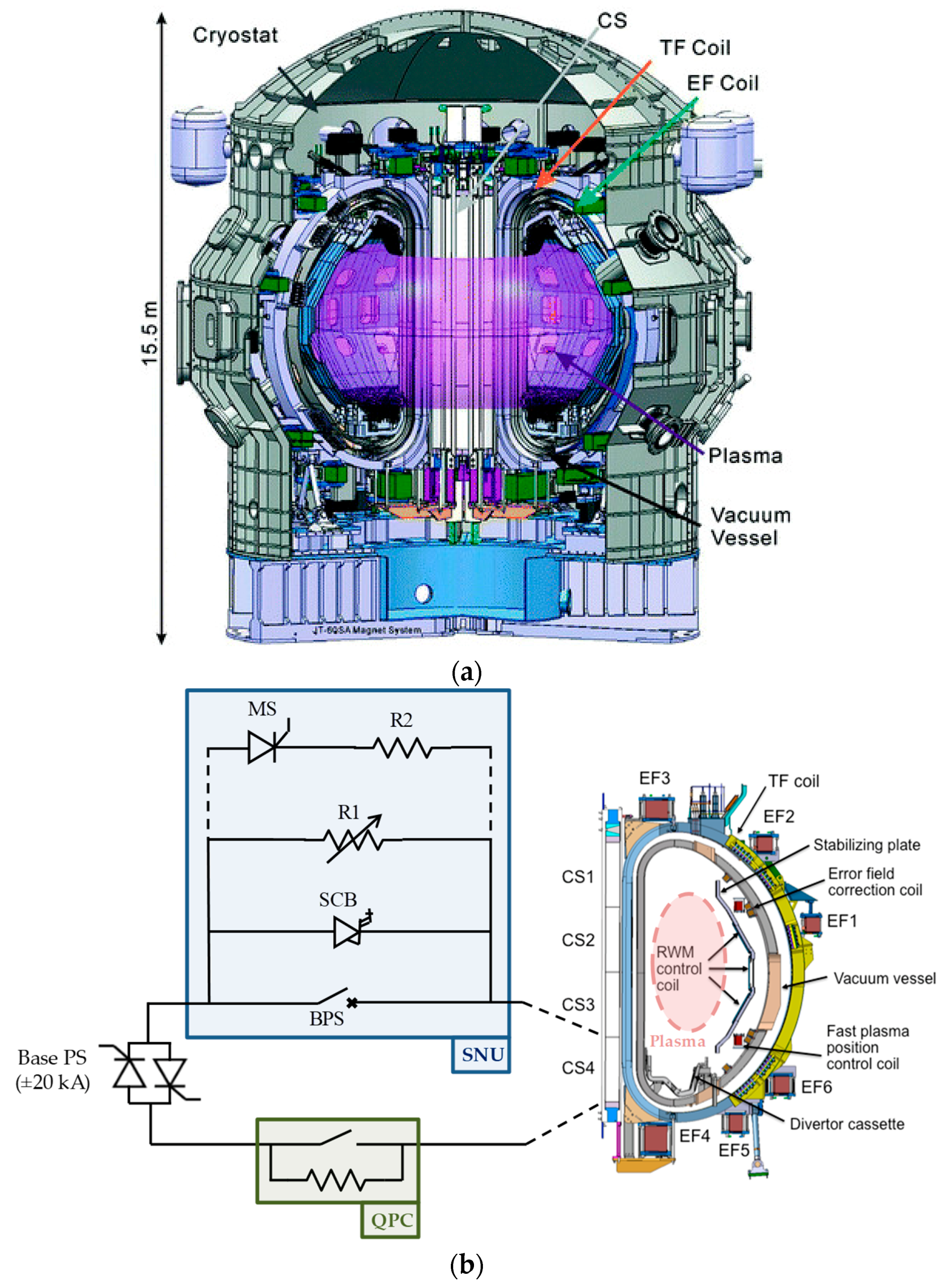
In a tokamak the CS acts as the primary winding of a transformer, while the secondary current is formed by the plasma ions flowing around the toroidal axis, as sketched in
Figure 1a. In modern tokamak devices, in order to achieve better performances, the CS is divided in modules connected to independent PS systems. The JT-60SA CS consists of four independent superconducting modules (denoted as CS1, CS2, CS3 and CS4), each one supplied by an independent circuit, as shown in
Figure 1b.
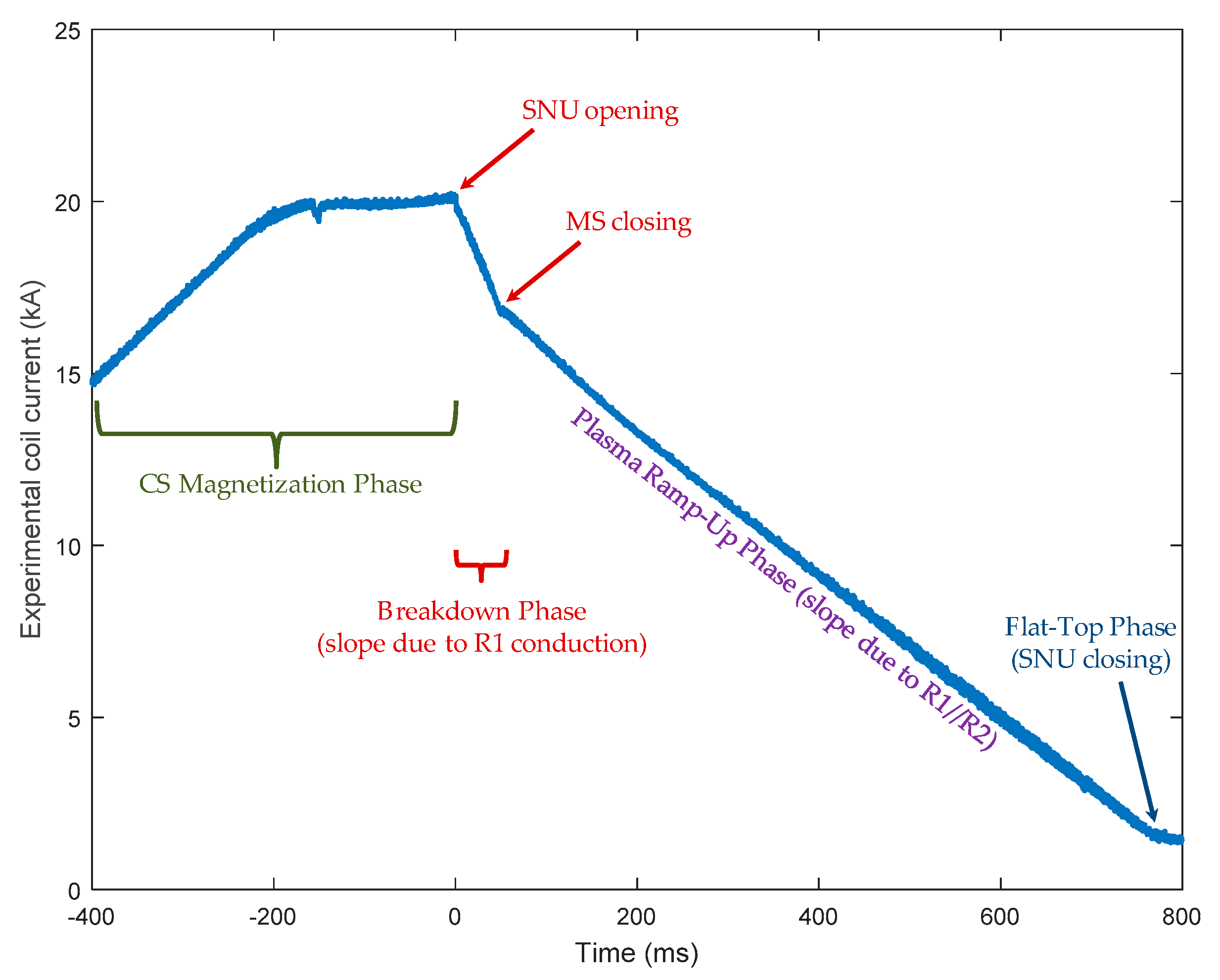
The main technique to initiate plasma in tokamaks makes use of a CS for inducing a magnetic flux variation and consequently an electric field inside the vacuum vessel along the toroidal axis. The CS operations are summarized in the following successive phases:
Coil Magnetization Phase (CMP): The CS is pre-charged (magnetized) with a current in the desired direction of the plasma current (forward current), up to the (forward) maximum value of the Base PS.
Plasma Breakdown Phase (PBP): The CS current is quickly decreased with the consequent overvoltage in order to induce in the plasma a toroidal loop voltage Vloop and the related electric field Vloop/2πr (where r is the tokamak radius in the center of the plasma).
Plasma Ramp-Up Phase (PRP): In order to make the plasma current growing with the proper rate up to the desired value (in the order of some megamperes), the CS current is decreased towards zero with a high derivative but lower than necessary for the breakdown.
Flat-Top Phase (FTP): After the plasma current reached the desired value (flat-top), it should be kept to this value as long as possible (as allowed by the tokamak coils and PSs). In this phase the CS current is mostly negative (backward current) and with relatively slow derivatives.
Coil Discharging (Demagnetization) Phase (CDP): The CS and consequently the plasma current are sent to zero with slow derivatives.
In order to explain these concepts in a real case, some of these phases are reported on an experimental waveform of the CS SNU current in
Figure 2. For convention, the zero of the time scale in tokamaks is fixed to the PBP starting time.
In principle, a Base PS could generate all the necessary current derivatives, but it would require an overestimation of all the components and operations, while the PBP and the PRP last few seconds. Therefore, it is more convenient to support the Base PS with a further system operating only during these short phases. Even though other solution may be proposed (and an example is given by the Booster PS in JT-60SA), a good idea is to exploit the magnetic energy stored in the CS by a SNU that is able to rapidly connect and disconnect proper resistors, called breakdown or discharge resistors, in series to the Base PS. The breakdown resistance RSNU introduced in the coil circuit by the SNU produces a negative overvoltage VSNU = −RSNU × Icoil proportional to the current Icoil flowing in the circuit at that moment. If only a single coil (CS module) is considered, the Vloop resulting from that coil can be roughly estimated as proportional to VSNU (with a different coupling factor for each module).
SNU operations are crucial for the tokamak experiments, as they allow the abrupt current derivatives and overvoltages required during PBR and PRP and perform an opening and closing succession in every meaningful experiment.
Figure 1b addresses the CS4 module circuit and its SNU, but the other three CS modules are supplied by similar circuits (with different transformers at the input of the Base PSs). The Base PS consists in a 4-quadrant thyristor-bridge AC/DC converter up to ±20 kA. The quench protection circuit (QPC) is necessary for the safe discharge of the energy stored in the superconducting coils [
5]. It is worth noticing that a SNU, or another system supporting the breakdown, is useful also in other tokamak coils, as the JT-60SA Equilibrium Field (EF) coils.
2.2. SNU Specifications
The specifications for the CS SNUs are summarized in
Table 1 and
Table 2. The tables also provide a comparison between the initial specifications and the achieved results. The specifications were firstly defined on the basis of the expected plasma behavior [
4,
5,
6]. The experimental values and the performed tests summarized in in
Table 1 and
Table 2 will be addressed in the rest of the paper.
The main requirements for the SNU deign consisted in a current interruption up to 20 kA with an overvoltage up to 5 kV in an opening/closing time shorter than 1.5 ms (including accuracy).
The “worst-case” SNU opening time is that obtained in non-nominal conditions, namely at currents lower than 20 kA. In fact, since the SCB snubbers and parasitic elements were optimized for the most important specification that is the opening time at nominal current, the opening time can be longer at lower currents (see also discussion in
Section 5.3 and [
8]). On the other hand, the SNU and MS closing times resulted to be shorter in non-nominal conditions.
2.3. SNU Final Design
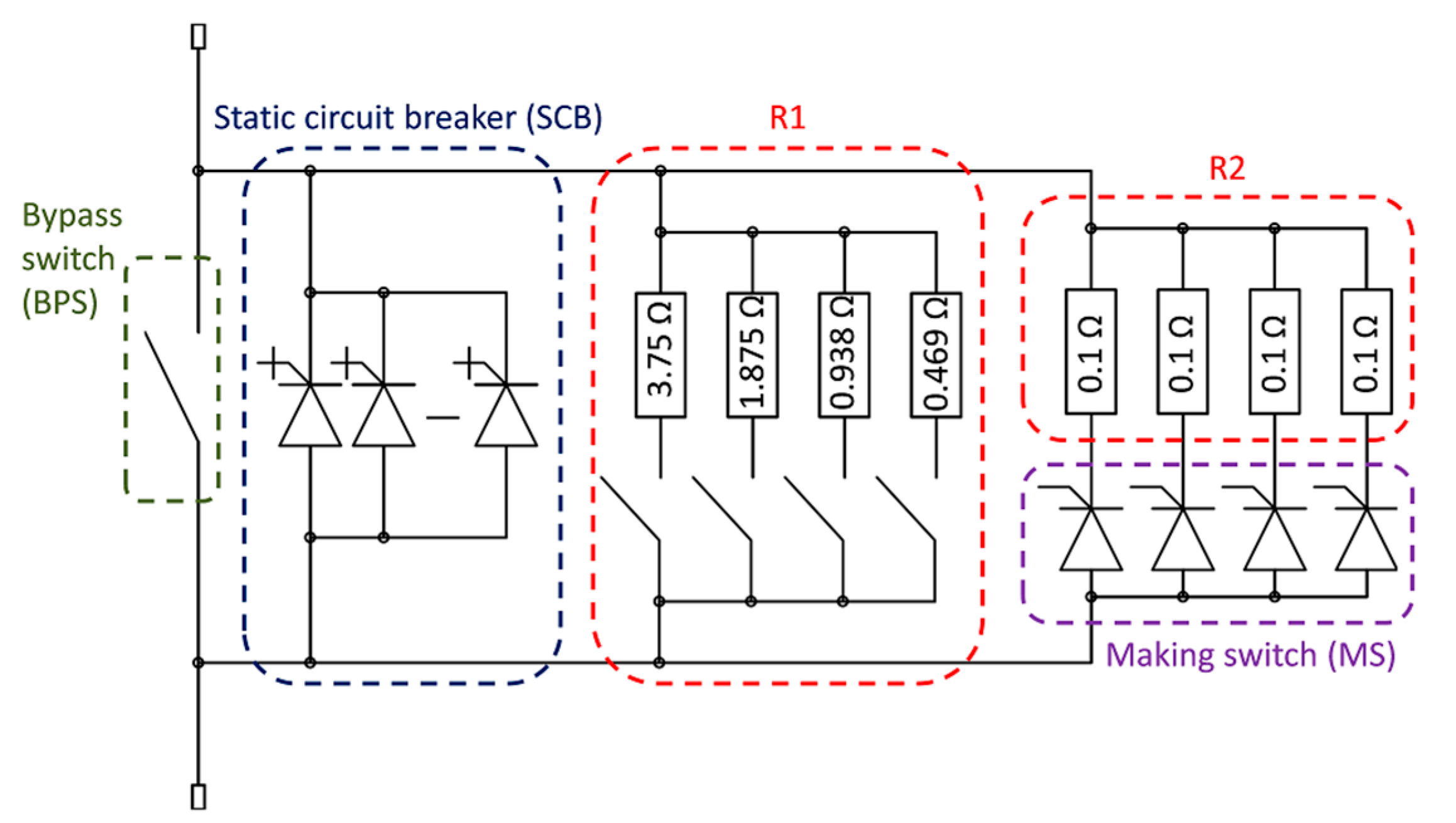
Figure 3 shows a simplified “as-built” scheme of a JT-60SA CS SNU. Even if the energy dissipated in the bank of breakdown resistors R1 and R2 could be different in the operations, the four CS SNUs are identical in the final design. Each SNU consists of four cubicles as it will be shown in
Section 4.
In order to allow a flexible selection of the obtained voltage, the breakdown resistor R1 is a bank of four resistors having different resistance value, that can be connected or excluded by means of motorized selectors before each experiment according to the desired scenario.
To obtain the rapid current variation needed for plasma breakdown, the resistor R1 is inserted in the circuit of each CS module after a pre-charge up to the maximum current of the Base PS (20 kA). To be able of interrupting a DC current for thousands of operations without major maintenance, a hybrid mechanical-static circuit breaker has been designed, consisting of a parallel of:
- (1)
A light electromechanical contactor, implementing the BPS.
- (2)
A SCB based on the parallel of eight IGCT stacks.
A BPS-SCB sequence is implemented at each SNU operation. Before the PBP, the SCB is turned-on before the BPS is opened. Even though the gates of the IGCTs in the SCB stacks receive the commands to turn on, they cannot conduct current due to the insufficient voltage drop at their terminals (the BPS resistance is lower than their equivalent resistance). The voltage of the arc appearing across the BPS opening contacts is sufficient to turn-on the IGCTs in the SCB parallel branches to completely divert in the SCB all the current flowing in the opening BPS. The experimental tests showed that the necessary arc voltage is lower than 20 V [
8].
The SCB is commanded to turn-off some milliseconds after the BPS contact opening and after verifying that the BPS is completely opened, so that the distance of the contacts is sufficient to withstand the reapplied voltage without risk of current re-strike.
The PBP starts when the SCB is turned off and the current can flow only through the resistor bank R1. This is also the zero of the tokamak time scale. In practice, the functional time for the SNU opening is the time necessary to divert the current from the SCB to R1. Then, the SNU time performances are determined by the SCB and, in particular, by the IGCTs that can commutated in less than 1 μs with a jitter lower than ±200 ns.
After the PRP, the opposite sequence is implemented: the SCB is commanded to turn-on and the current is bypassed from the resistors into it; successively the BPS is closed and, having a lower impedance path, the current is finally transferred from the SCB to the BPS.
In this way, the SCB operations virtually hide the inadequate velocity and repeatability of the BPS and limit its opening stresses and arc phenomena, improving the expected component lifecycle and reliability [
6]. On the other hand, the global power losses are limited because during the period in which the SNU is not operating the current flows only through the BPS that is characterized by negligible conduction losses.
In principle, the current transfer from the SCB to the bank R1 has to be rapid to ensure a good turning of the IGCTs. Nevertheless, also due the parasitic elements, this transfer can generate transient overvoltages that can significantly exceed the value desired for the breakdown. This results in stress on the components, as the CS superconducting coils and the semiconductors (IGCTs, diodes), that could be detrimental, especially after years of operations. Therefore, the SNU maximum voltage, including overshoots and transients, must be limited as much as possible. This was mainly achieved by controlling and preliminarily verifying the parasitic reactances in the breakdown resistors and in the SNU connections. A further improvement was obtained by means of a patented snubber operating in two-stages: the first stage acting as a conventional snubber, whilst the second stage is triggered when the voltage across the SNU achieves a prefixed threshold value. This value is prefixed according to the coil current that must be switched. For example, it can be equal to the nominal voltage to be generated at breakdown, that is 5 kV maximum. The currents in the IGCTs fall at high rate until the SNU voltage reaches 5 kV, afterwards the rate is reduced by the second stage. At this reduced rate the effect of the parasitic reactances and the related overvoltage are limited, leading to a voltage overshoot below 5%.
The 5-kV voltage is required in JT-60SA for plasma breakdown, but a lower voltage and current derivative are desired for the PRP. The SNU implements this reduction by inserting a second breakdown resistor R2 in parallel to R1. This is obtained by operating a dedicated Making Switch (MS) composed of four thyristors in parallel. The actual instant
TFTP in which the SNU is reclosed and the FTP can start depends on the experimental scenario. Since each MS thyristor has a 100 mΩ resistor in series (see
Figure 3), it is possible to flexibly select the desired value of the PRP resistance by changing the number of triggered thyristors.
Even though the Base PS can operate in 4 quadrants, the current can flow through the SCB and the MS of the SNU only in one direction. If requested by the experiment, some manual current reversing links allow the inversion of the current in the CS. Of course, since the BPS is bidirectional, the current in the short-circuited SNU can be conducted in both directions. The SNU operations are summarized in
Table 3.
The JT-60SA Supervisor Computer (JSC) does not need to know and manage the exact BPS/SCB sequences. Such sequences are totally synchronized by a Local Control Cubicle (LCC) of the SNU, that is a computer with interfaces to all the cubicles of the four CS SNUs (see
Section 4). The LCC normally operates in remote mode following the instructions of the JSC and sending to it all the internal measures in real time, but it can operate also in local mode as a human-machine interface for test and maintenance activities. In remote mode, the JSC writes to a shared Reflective Memory the global “Plasma Operation Timer” and the times desired for the SNU operations (coherent with the operations of other tokamak systems). The LCC reads this information from the Reflective Memory and, knowing the durations and delays of its own operations, manages the commands for the SNU devices with the proper time shifts. The resulting operation times are equivalent from a functional point of view. Also in order to improve the coordination of all the four CS SNUs, a single LCC was used to control them.
3. Activities of the CS SNU Procurement
The JT-60SA international project team (including ENEA, F4E, and QST) worked on the CS SNU Technical Specifications until 2012 when the Call for Tender was issued. The company OCEM Power Electronics was selected as industrial supplier for this procurement.
The SNU detailed design was approved by the JT-60SA Project Leader in July 2013. Due to the criticality of the SNU operations, a complete full-scale SNU prototype was firstly developed and an exhaustive set of tests was necessary to validate its design and manufacturing. The general choice was to use this prototype as first SNU of the procurement.
Several tests were performed in 2013 and 2014 both on single critical components and on the complete SNU prototype (type tests) [
7]. Some outcomes of these tests are reported in
Table 1 and
Table 2.
The most relevant tests were performed by implementing the SNU prototype into the PS circuit of the CS coil of the ENEA Frascati Tokamak Upgrade (FTU) [
7] that is composed by a single copper coil. The SNU was tested even at full current (20 kA) and full voltage (5 kV). However, as the total inductance of the FTU coil (≈80 mH) was lower than the nominal value of a JT-60SA CS module (290 mH), the test scenarios were adapted to close the MS and the BPS at significant currents. Nevertheless, some test conditions, as the repetition time shorter than 1800 s, were worse than in JT-60SA.
Having successfully proved the fulfilment of the requirements, the further 3 SNUs (series SNUs) were manufactured and tested from 2014 to 2015 [
8]. The tests performed on these SNUs (routine tests) were less demanding than the type tests, as summarized in
Table 1 and
Table 2.
In order to perform functional tests on all the SNUs, the complete procurement (four SNUs together with the LCC) were assembled in the OCEM factory in a configuration similar (but with less space available) to the final installation in the JT-60SA Rectifier Room at the Naka site.
During all the functional tests, the SNU operations were managed by the final LCC and were supervised, through a specific Reflective Memory network, by a test stand emulating the functions of the JSC in order to reproduce as much as possible the final situation in JT-60SA.
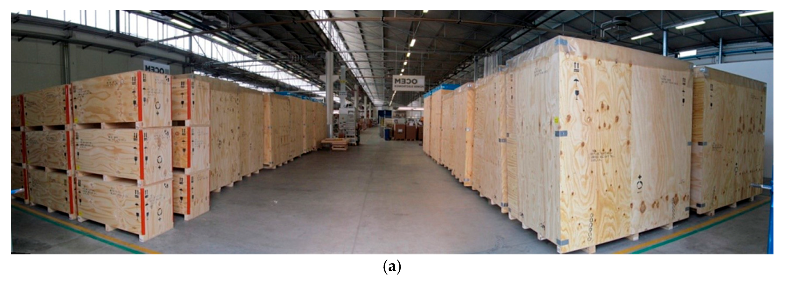
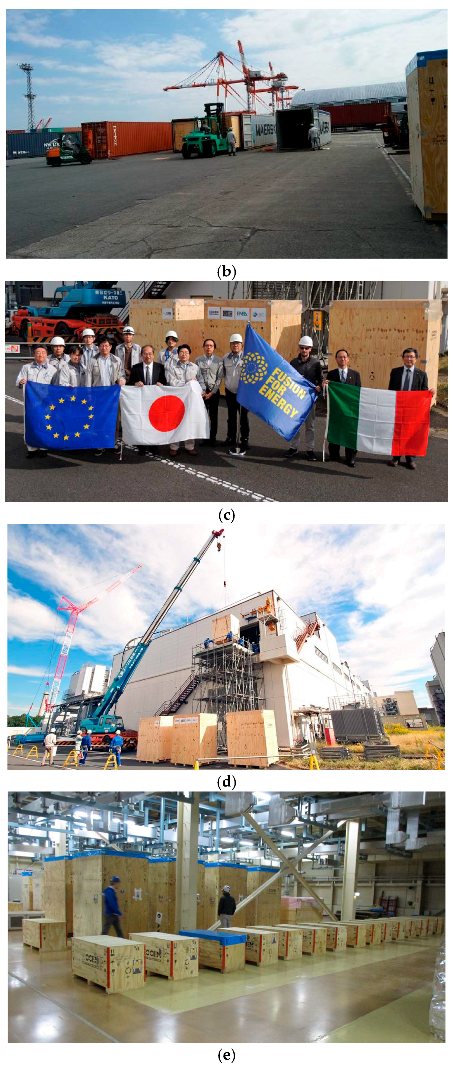
The main phases of the SNU shipment are summarized by the pictures in
Figure 4. After been packed into 52 wooden cases with a total weight of about 50 ton, the four SNU have been delivered to Japan, where the installation activities started in October 2016.
Figure 4a shows the 52 wooden crates ready for shipment in OCEM premises before leaving for Japan. The crates were loaded in five containers for sea transportation, as shown in
Figure 4b. The SNUs and related accessories were delivered to Japan in October 2016 for the on-site activities to be completed by 2017.
4. On-Site Installation and Commissioning
It is important to stress that the JT-60SA project is a (superconducting and advanced, SA) update of the previous experiments JT-60 and JT-60U. Therefore, the SNU system had to be placed and installed in an existing room (denoted as Rectifier Room) that needed to be adapted for the new plant.
The installation phase in Naka, including unboxing, positioning, electrical connection between the power cubicles and signal connection between the power cubicles and the LCC, took about eight weeks by using a local contractor providing a team of nine operators supervised by the OCEM technical responsible.
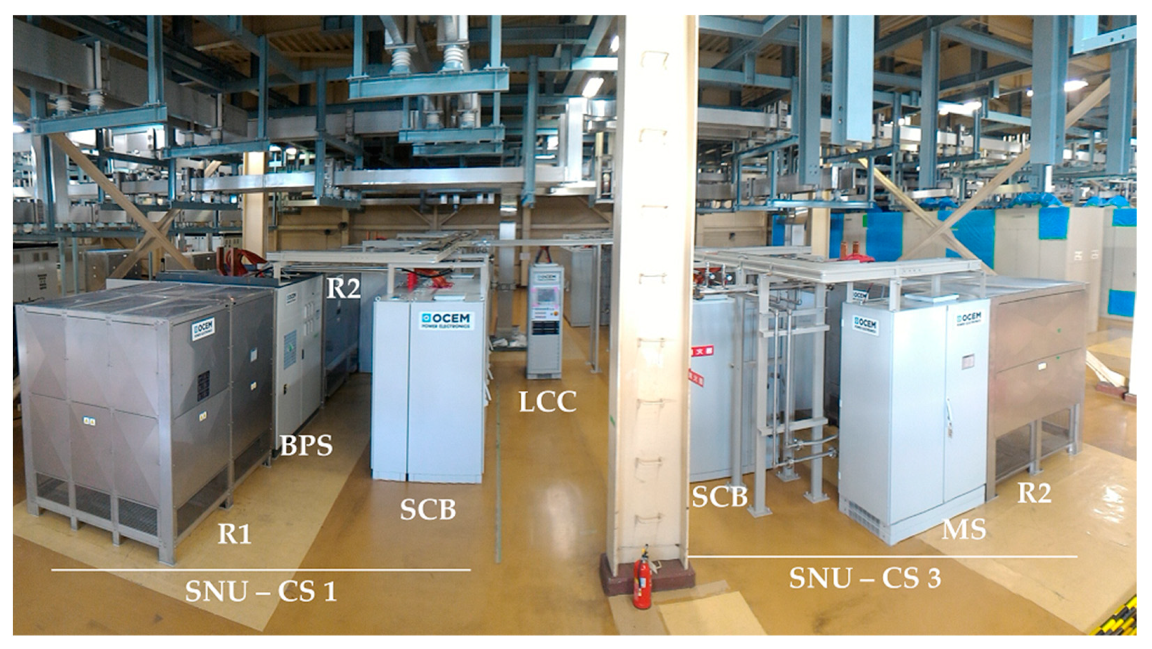
A picture of the components as placed in their final position is shown in
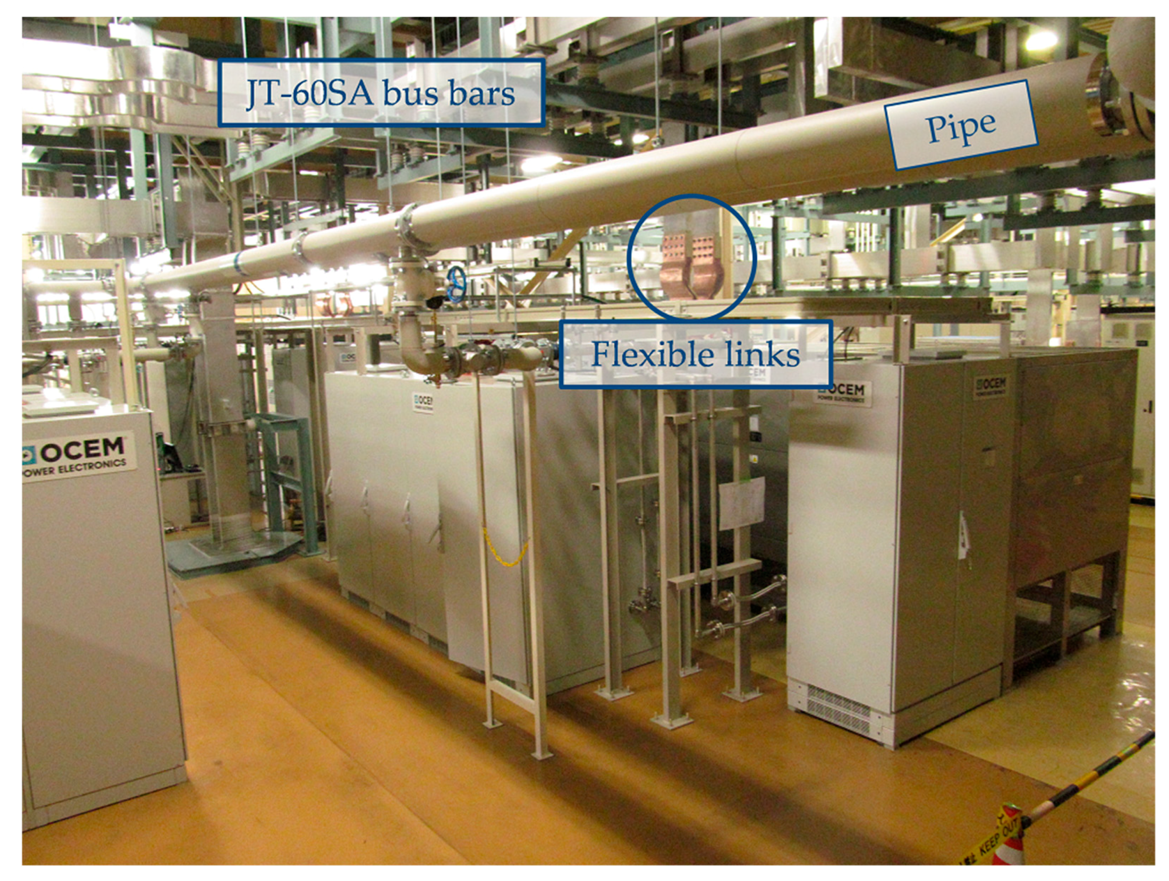
Figure 5, while
Figure 6 shows the situation after the connections of such components to the CS circuit and to all the JT-60SA services and external systems (demineralized cooling water, auxiliary PS, communication interfaces, interlocks and so on).
As visible in
Figure 5, the components of each SNU are enclosed inside 5 cubicles, containing respectively:
The BPS with supercapacitor-based auxiliary PS, grounding switch and selectors.
The SCB with water cooling system.
The electronic MS with water cooling system.
The breakdown resistor bank R1.
The breakdown resistor bank R2.
Therefore, the complete SNU system consists of 21 cubicles, including also the LCC, that is common for all the four SNUs.
The commissioning activities started in January 2017, after connecting the auxiliary systems (auxiliary voltage and cooling water). The final result is shown in
Figure 6.
The SNU terminals, located on the top of the BPS cubicle, are connected to the aluminum DC bus bars of the CS circuit by special flexible links (see
Figure 6), made by copper with a coating for copper-aluminum interfaces. The link flexibility is useful to compensate possible small position misalignments and stresses due to seismic events.
The pipes for the demineralized water are delivered to each SNU and there are used for the SCB and the MS cooling. The water flow rate for each SNU is 68 L/min. Most of such water is required for the MS (48 L/min), especially in case it has to sustain a long operation due to a BPS fault. The water in the SCB is not necessary during the conduction, also because it is very short (≈200 ms), but it ensure to start each operation at the prefixed and safe temperature (<35 °C). All the type and routine functional tests (also at full current and full voltage) were performed without water cooling, while it was included during the on-site tests (addressed in
Section 5), even though the current was significantly lower than the maximum one, in order to verify all the systems including cooling detectors and alarms.
The LCC is the small cubicle placed in the middle of the SNU area in
Figure 5. All the signal from/to the JSC are connected to the LCC that manage the internal communications with the SNU cubicles. The LCC was placed in central position also to achieve similar communication times with all the SNU components.
Two types of auxiliary PSs were provided to the SNUs: a standard one and an uninterruptible power supply (UPS) for the most critical loads. Nevertheless, even in total absence of PSs, the SNU BPSs can be reclosed and kept closed by the supercapacitor-based PSs and by some mechanical anchors, respectively. The connection to diesel emergency generators available in JT-60SA was not necessary for the SNU.
The commissioning without power consisted in verifying the correct installation, the safe working of all components and the operation of the control system including protection logic in anomalous condition.
In addition, an improvement of the mechanical system for the operation of the BPS has been implemented during the commissioning in order to increase its reliability and to simplify the mechanical calibration of the BPS without modifying its functionality. The improvement, suggested and implemented by the BPS manufacturer, consisted in the substitution of the material of some dumping elements and in a modification of the lever mechanism of the anchors blocking of the BPS in closed position.
5. On-Site Tests
5.1. Preliminary Tests
After the installation, the voltage withstand test has been positively performed on all the power units applying a voltage to ground of 5 kV rms for 10 min. Successively, the water cooling pressure test has been passed by pressurizing the cooling pipe circuit with a pressure of 8.25 bar for 30 min.
5.2. Functional Tests
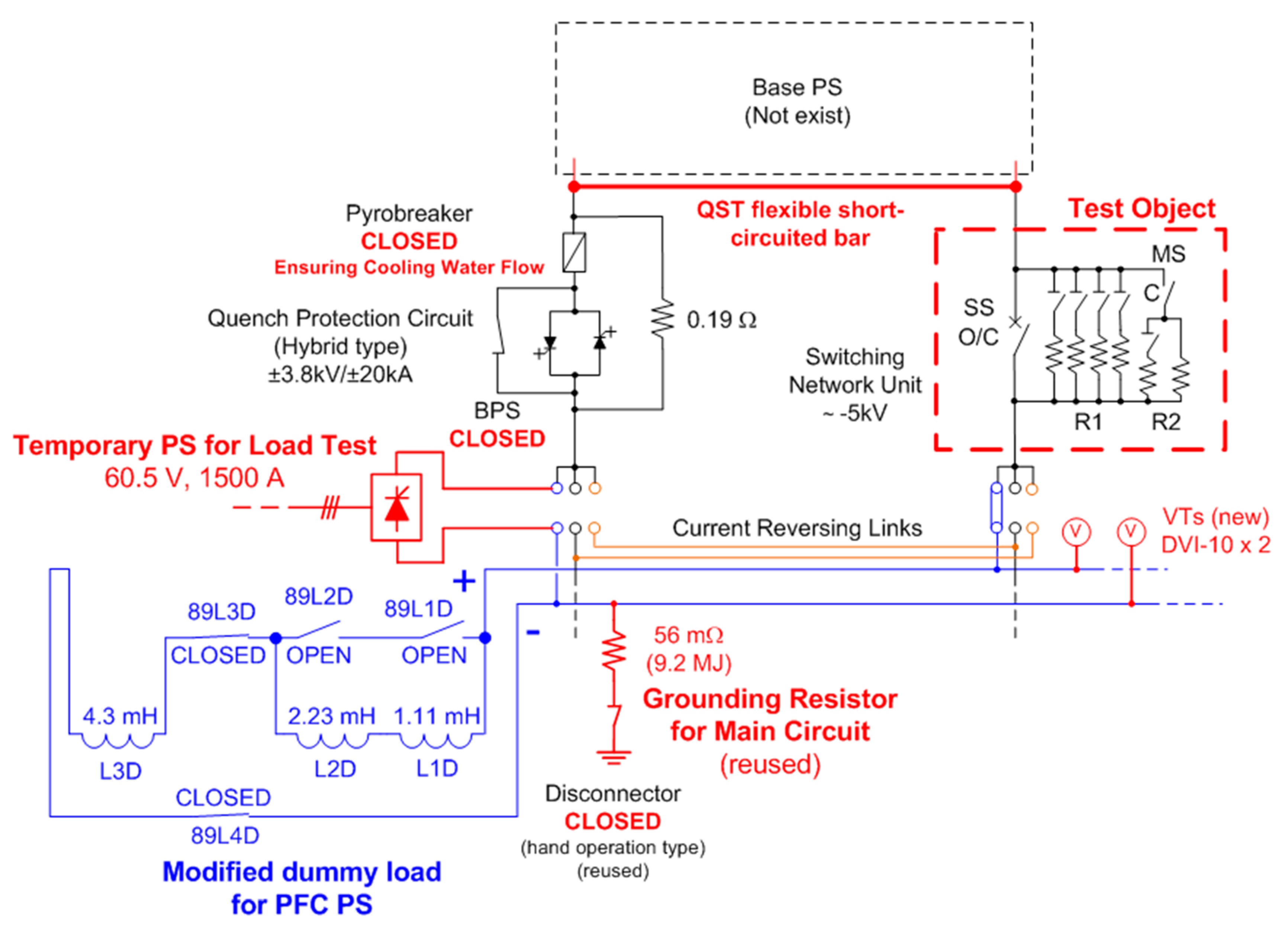
The functional acceptance tests have been performed in March 2017. Since the CS magnets and their final converters were not yet available, the tests have been performed connecting each SNU in a circuit with a temporary PS having a current limitation of 1.5 kA and with a dummy load of about 8 mH, as described in
Figure 7. Even if with reduced current, these tests reproduced a complete cycle of SNU operations, including the combined operations of the hybrid mechanic-static switch and the MS insertion.
An emulator of the central control system of JT-60SA (JSC) has been used for the test, simulating its communication with the SNU LCC. The communication is implemented through a Reflective Memory: the emulator was used to set remotely the R1 configuration and the timing of the events occurring during the current cycle (time of SCB opening and closing and of MS closing) and to collect the data relative to the measurement acquisitions (currents, voltage, temperatures), status and interlocks. Opportunely setting the value of the R1 resistor it was possible to produce a voltage of about 4.5 kV, close to the nominal voltage of 5 kV, even with the reduced current available for the tests, therefore it was possible to effectively test the correct operation of the SNU under almost nominal voltage conditions.
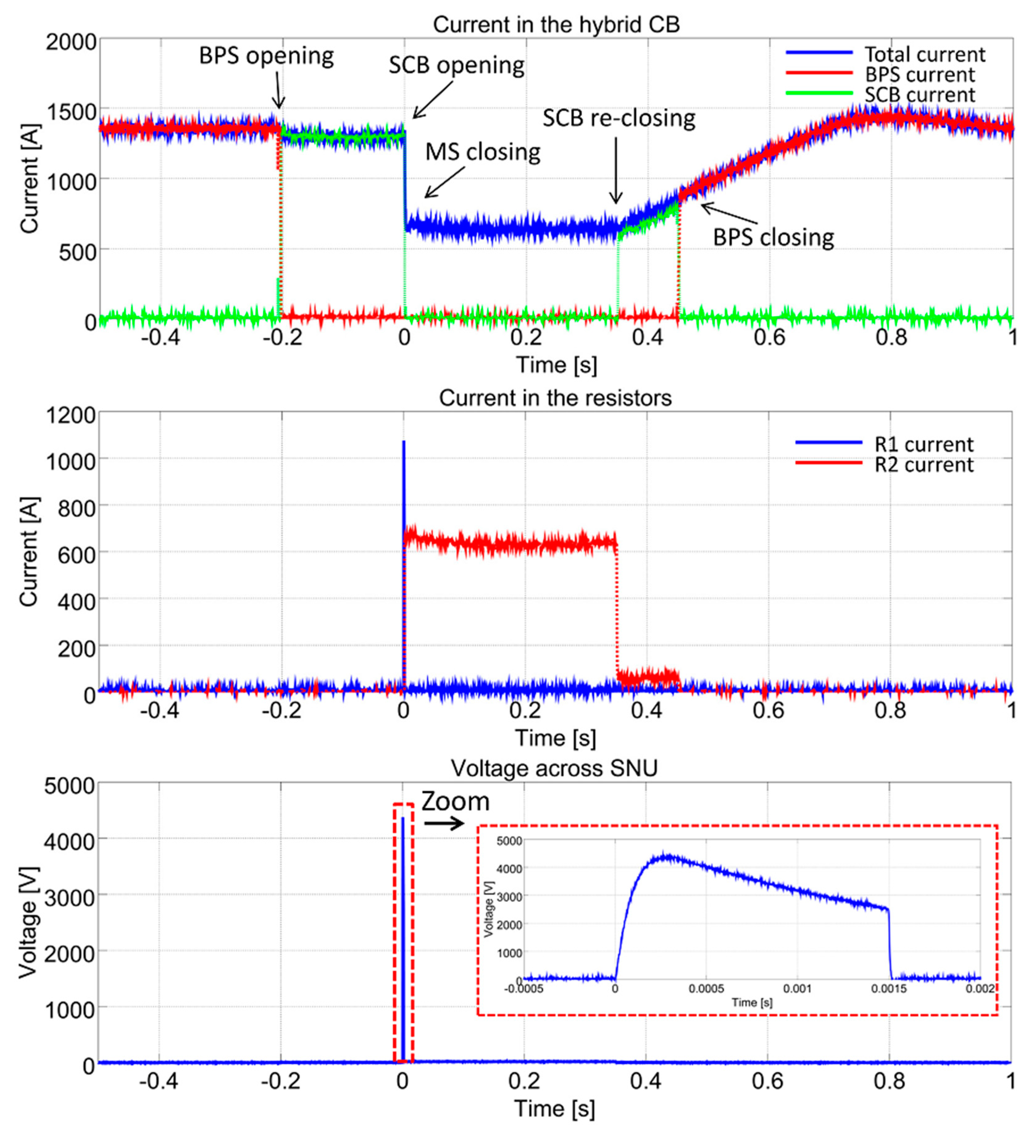
For each SNU, five current cycles have been performed, using two different configurations for the R1 resistors, reproducing the same conditions realized during the factory routine tests. Three cycles have been executed with R1 = 3.75 Ω, reaching the highest voltage, and two with R1 = 0.25 Ω. An example of the obtained waveforms is shown in
Figure 8.
5.3. Discussion of Test Results
The following quantitative criteria were verified during the tests:
The SS switch-off time, defined as the time required to achieve the 2% of the initial SS current from the opening command of the SCB, must be lower than 1.5 ms.
The SS switch-on time, defined as the time required to achieve the 98% of the expected current starting from the SCB command, must be lower than 1.5 ms.
The MS switch-on time, defined as the time required to achieve the 98% of the expected current starting from the MS command must be lower than 2 ms.
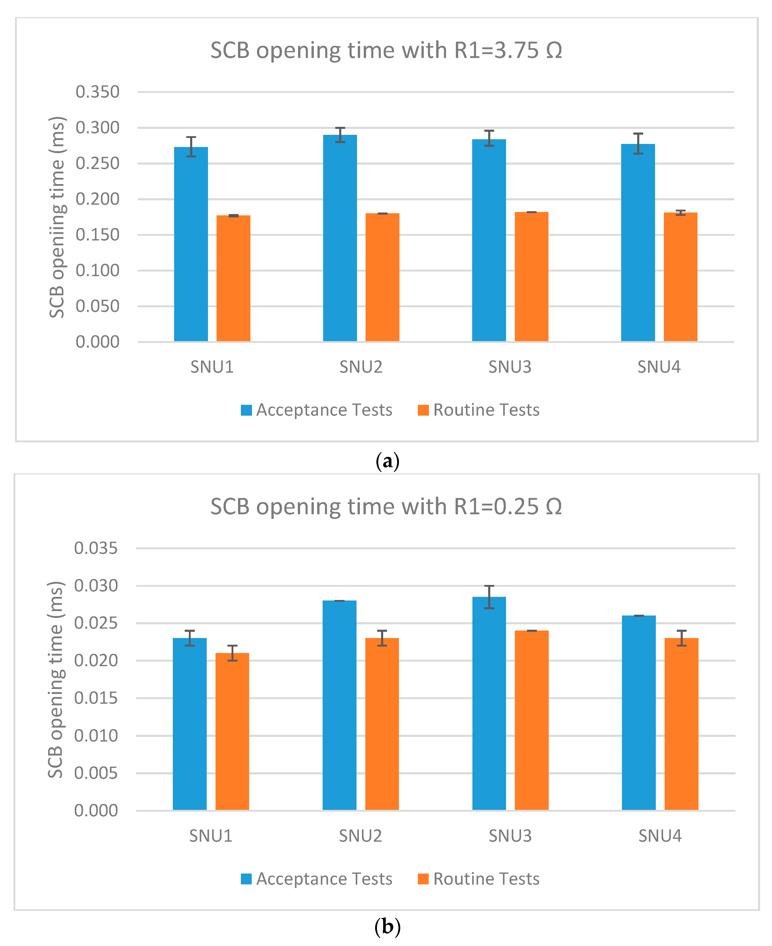
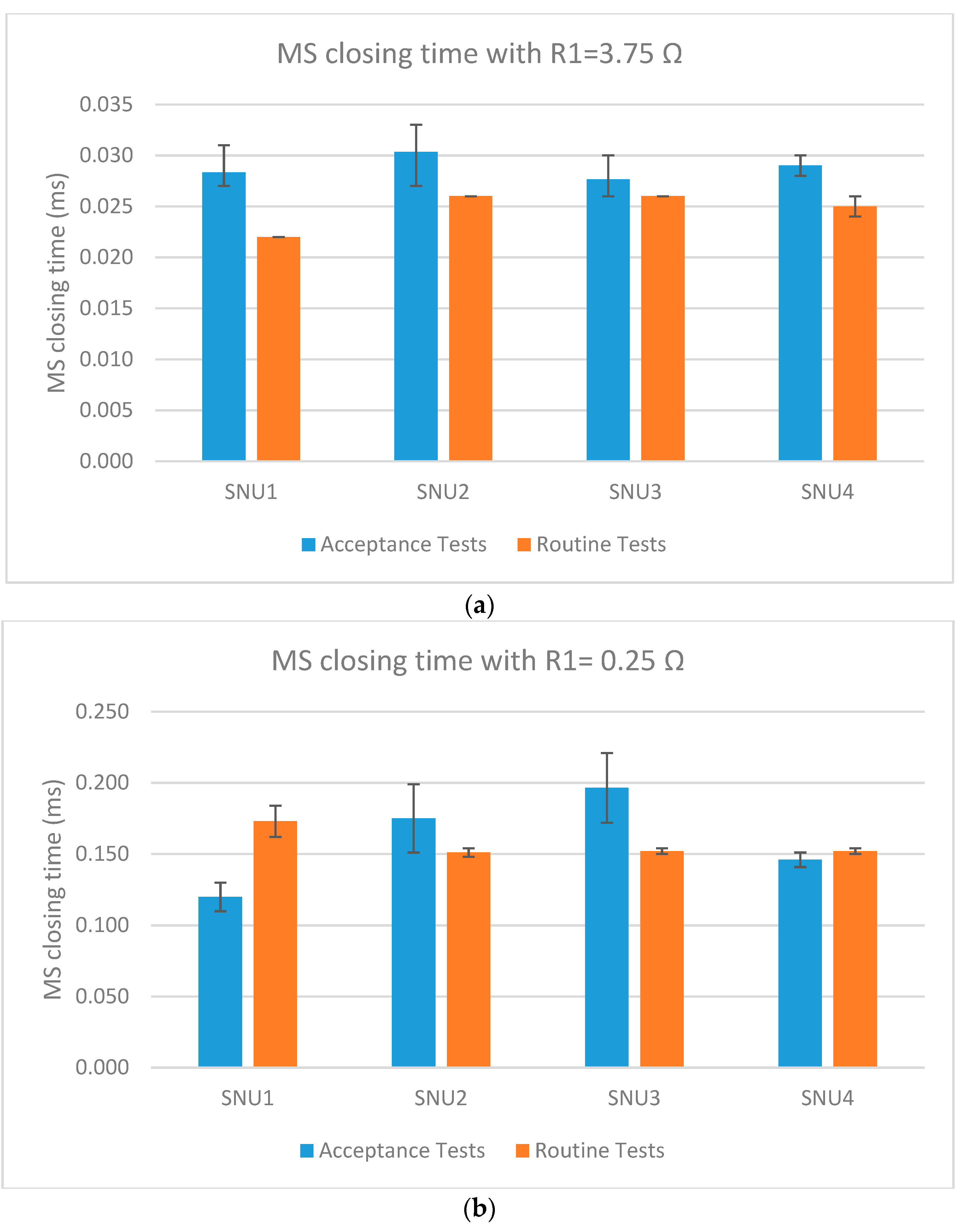
The bars in
Figure 9 and
Figure 10 present an overview of all the routine tests performed in the JT-60SA premises together with the factory tests performed in the OCEM premises in Italy. The results complied with the specifications (see
Table 1) with great margins especially for SCB opening time and MS closing times. In particular, the results of the on-site tests showed a good compliance with those of the factory tests, as summarized in
Figure 9 and
Figure 10. The same tests have been repeated several times and the average values are showed in
Figure 9 and
Figure 10, together with an error bar indicating the dispersion of the values measured in the different tests on the same SNU.
The reduced dispersion of the obtained results with the same SNU (within ±14 µs for the SCB opening and within ±24 µs for the MS closing) confirms the repeatability of the operation performances of each SNU. The test dispersions between the different SNUs (within ±20 µs for the SCB opening and within ±55 µs for the MS closing) are also relevant because a good synchronization and time accuracy among different coils and experiments is requested to control plasma initiation. These dispersions are due to the experimental uncertainties, to the tolerances in the devices belonging to different SNUs, to the synchronization jitters. There are no specific needs to furtherly characterize these contributions or to reduce them for the SNU applications. In fact, even the worst-case differences (50 µs for the SCB opening and 110 µs for the MS closing) are well included in the specifications in
Table 1 (500 µs and 1 ms, respectively) and in the refresh time of the JSC Reflective Memory (250 µs). It is fair to notice that the dispersions may be wider at higher currents but also that the tests clearly showed that the opening time is shorter at higher currents [
8], as reported in
Section 2.2.
In addition, it should be noted that the different values measured for the opening and closing times are depending also on the actual current value at the time of SCB and MS operation. In general, the current values used for the on-site acceptance tests were slightly higher (initial value about 1.4 kA) than the values used for the routine tests in factory (initial value about 1.25 kA), therefore the SCB opening times obtained during on-site tests are generally higher.
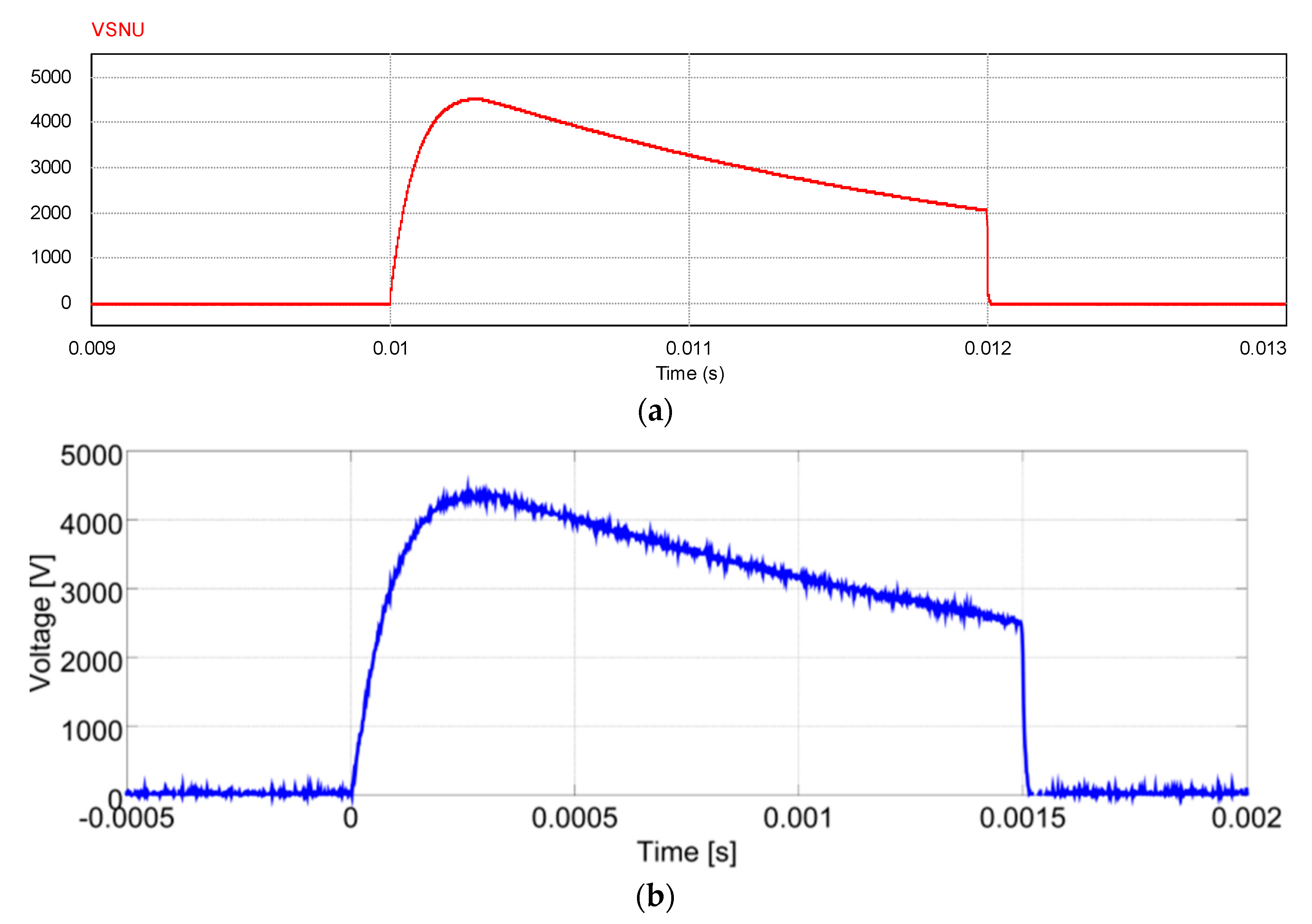
Figure 11 stresses the remarkable qualitative and quantitative agreement between the experimental results and the outcomes of the preliminary simulations carried out with the detailed computer model used for the SNU design [
6]. That model was implemented using two different simulation tools (Cadence/PSpice and PSIM) to verify the behavior of the same circuit. The model took into account the discrete components (e.g., IGCT and diodes and related snubbers including conduction and recovery characteristics) and the stray inductances of commutation loops. These were estimated from geometries of the semiconductor assembly. The simulations were repeated inserting the parameters obtained from the first prototypes of the single components (single units of R1 and R2 resistors, cubicles, connections cables, semiconductor stacks). Having verified that the circuit model gave the same result with both simulation tools (and the voltage margin was reasonably safe) a real prototype was assembled and tested.
Nevertheless, the SCB opening time obtained during the on-site tests resulted longer than the time obtained during the factory routine test. This difference could be explained considering that the dummy load used for the on-site test had higher inductance (8 mH) compared to that used for the factory test (1 mH). The inductive load can reduce the current flowing in the test circuit at the SCB opening, resulting in a shorter opening time. In other words, the use of different load values corresponds to performing the SCB opening operation with different current values to be interrupted. On the other hand, the current evolution also depends on the used PS. In fact, even shorter times (<100 μs) were measured during the tests in the Frascati Tokamak Upgrade (FTU) where the inductance was about 80 mH [
7,
8], closer to the JT-60SA CS inductance (290 mH). In any case, all these values are well below the maximum allowed limit (1.5 ms).
Finally, due to the SNU safety and reliability requirements, all the fault conditions were considered in the design and in the tests. The behavior in case of simulated faults was verified. Moreover, all the components are oversized. In particular, in case of fault, the breakdown resistors and the MS would be able to sustain and dissipate all the magnetic energy stored in the CS coils, the BPS can sustain an I2t double than the nominal one, the SCB can operate in absence of water cooling for some cycles, and so on.
6. Conclusions
The possibility to control nuclear fusion on the Earth would introduce a new energy source with several potential benefits. For these reasons, many international projects are under way to investigate this phenomenon. JT-60SA is an international tokamak being built in Naka (Japan) as a joint collaboration between Europe and Japan.
The procurement of the different systems composing JT-60SA is managed as in-kind contributions shared between European and Japanese institutions. In this framework, the procurement of the CS SNUs is supported by Europe. The main SNU function is to interrupt a high current (up to 20 kA) in a short time (less than 1 ms) to produce an overvoltage up to 5 kV. After a 4-year design and manufacturing in Europe, the JT-60SA CS SNUs and the related components were delivered to Japan in October 2016.
This paper described the activities for the on-site installation, commissioning and tests of this procurement. The installation and commissioning activities were complete in February 2017.
The functional acceptance tests were performed in March 2017. Since the CS magnets and their final converters were not yet available at that time, the tests were performed connecting each SNU in a circuit with a temporary PS and a dummy load. Even if with a reduced current, these tests reproduced a complete cycle of the SNU operations.
The results showed great margins with respect to the project specifications, a remarkable agreement with the simulations carried out for the initial design and with the results of the factory tests performed in Italy.
Even if the SNUs were optimized to operate in the JT-60SA CS or in other tokamak coils, their design and manufacturing principles could be applied and extended in many fields where it is necessary to switch a high DC current, as HVDC. The extension to higher currents and voltages is viable by increasing the semiconductor devices in the SCB or by coordinating more SNUs in parallel or in series.
The important international collaboration behind the JT-60SA project is proceeding producing the expect results. In particular, the SNU installation, commissioning and acceptance tests were completed according to the schedule.
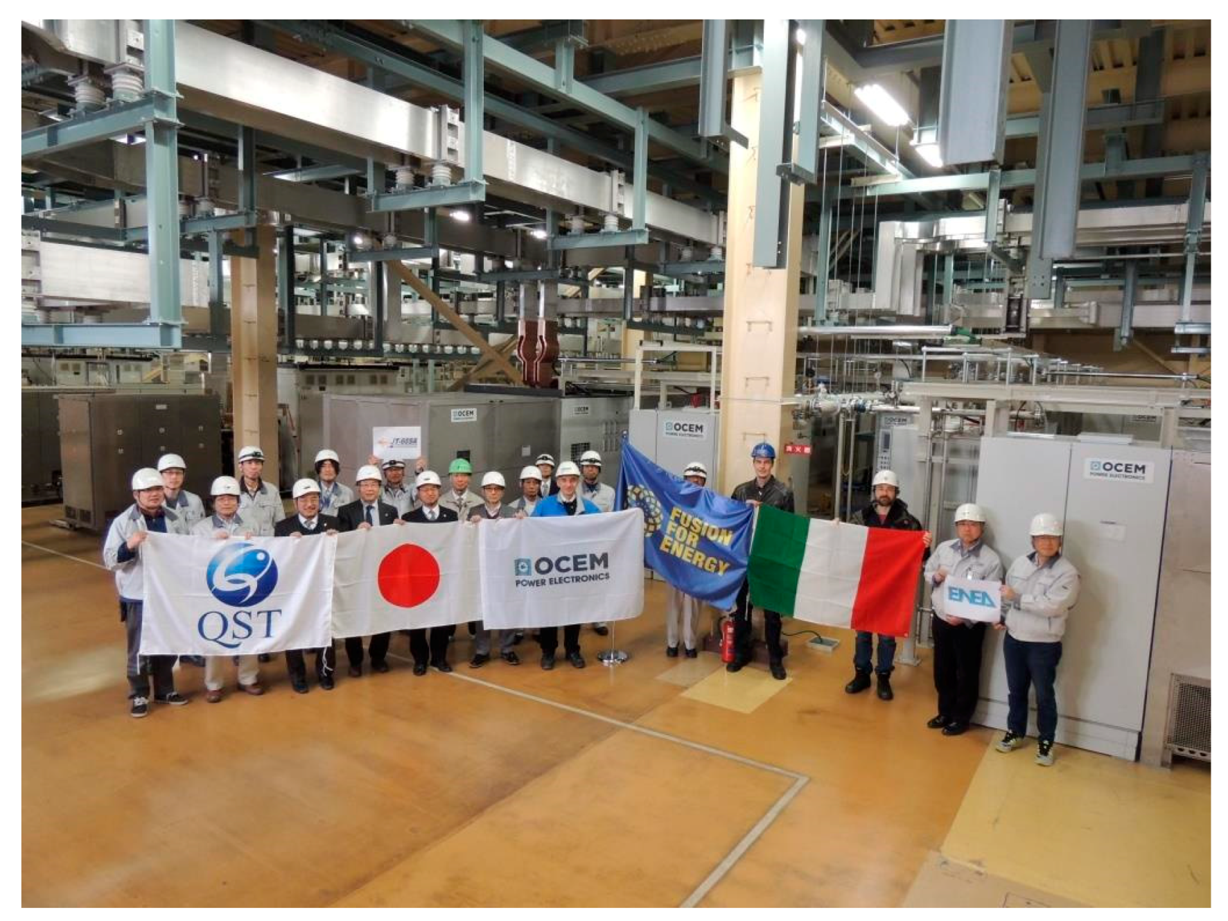
Figure 12 shows the celebration after the successful completion of the test on the four SNUs. The SNU operation shall be verified in integrated tests together with the other PS components before the 2019, when the first JT-60SA plasma experiment is scheduled.

 ,
, 


