Article

Experimental Research of a Water-Source Heat Pump Water Heater System

School of Energy and Power, Jiangsu University of Science and Technology, Zhenjiang, 212000, China
*
Author to whom correspondence should be addressed.
Energies 2018, 11(5), 1205; https://doi.org/10.3390/en11051205
Submission received: 9 April 2018 / Revised: 3 May 2018 / Accepted: 5 May 2018 / Published: 9 May 2018
(This article belongs to the Special Issue District Heating)

Abstract

:
The heat pump water heater (HPWH), as a portion of the eco-friendly technologies using renewable energy, has been applied for years in developed countries. Air-source heat pump water heaters and solar-assisted heat pump water heaters have been widely applied and have become more and more popular because of their comparatively higher energy efficiency and environmental protection. Besides use of the above resources, the heat pump water heater system can also adequately utilize an available water source. In order to study the thermal performance of the water-source heat pump water heater (WSHPWH) system, an experimental prototype using the cyclic heating mode was established. The heating performance of the water-source heat pump water heater system, which was affected by the difference between evaporator water fluxes, was investigated. The water temperature unfavorably exceeded 55 °C when the experimental prototype was used for heating; otherwise, the compressor discharge pressure was close to the maximum discharge temperature, which resulted in system instability. The evaporator water flux allowed this system to function satisfactorily. It is necessary to reduce the exergy loss of the condenser to improve the energy utilization of the system.

1. Introduction

Energy used for hot water supply is the fourth largest energy user in commercial building sectors, after heating, air conditioning, and lighting. In the United States (USA), nearly 40% of homes use electricity to heat water, accounting for 17% of all residential site energy use. Therefore, it is essential to apply efficient and energy-saving heating equipment instead of traditional electric hot water systems [1]. Heat pump technology (e.g., air source heat pump, ground source heat pump, and solar-assisted heat pump) is an efficient and energy-saving technology [2,3,4]. The heat pump water heater (HPWH), a water heating equipment that can supply the equivalent amount of hot water with an efficiency that is twice or three times that of a traditional gas or electric water heater has drawn extensive attention recently for its high efficiency, energy-saving, and environmental friendliness [5].
As an efficient and renewable energy utilization system, the HPWH can utilize abundant natural resources. At present, the air-source heat pump water heater has been widely studied and applied due to its comparatively higher energy efficiency and environmental protection. The coefficient of performance (COP) of the air-source heat pump water heater is directly related to the air temperature. However, the temperature and humidity of air vary greatly, and thus it can’t provide a stable heat source. It is well known that water is a renewable, abundant, and concentrated heat source for HPWHs. In contrast, water-source heat pump systems have high COP values and high reliability with low maintenance. Till now, the heating performance of the heat pump has been extensively studied using water as the heat source.
The seawater-source heat pump (SWHP) has been extensively used for heating and cooling with the development of ocean energy exploitation. It is superior to air-source heat pumps at a low ambient temperature in winter [6]. Zheng et al. [7] conducted experiments to research the thermal performance of the helical coil heat exchanger (HCHE) in seawater in icy conditions. A mathematical model was developed to predict the heat transfer process of the HCHE, which can be used for the designing of the SWHP systems. Zheng et al. [8] compared the thermal performances of the beach well infiltration intake system (BWIS) with the helical coil heat exchanger (HCHE) for SWHP systems in severe cold regions during winter, indicating that BWIS had a better thermal performance, and HCHE for SWHP systems had a higher economic value. Baik et al. [9] researched the performance improvement potential of SWHP through TRNSYS software. They simulated the annual heating performance of a single-unit heat pump and 2, 3, and 4-series-connected heat pumps, which were improved by 8~14%. Shu et al. [10] conducted a field measurement of a seawater-source heat pump heating system, showing that the energy dissipated by the heat pump units dominated the entire system. They also analyzed the energy efficiency improvement potential of the heat pump units. Zheng et al. [11] established and validated models that described the heat transfer and coupled seepage course of beach well infiltration intake systems (BWIS) for a seawater-source heat pump. In addition, the performance of the BWIS was simulated.
Typically, a great deal of heat is stored in wastewater, and heat pumps can use this water as a renewable energy source for heating. Wastewater has many advantages, such as good temperature stability and high temperature in winter as a low-grade heat source. Postrioti et al. [12] realized an experimental device to evaluate the wastewater energy potential in civil buildings. Araz et al. [13] evaluated the performance of two combined systems, the wastewater-source heat pump (WWSHP) system and building-integrated photovoltaic (BIPV) system, using both energy and exergy analysis methods. This system conserved energy better and consumed less than gas-fired boilers. Liu et al. [14] proposed a multifunctional heat pump system that utilized gray water as the heat source. Wang et al. [15] simulated and analyzed three sorts of rotating flexible heat transfer tubes by Fluent software, managing to enhance the heat transfer performance of the wastewater heat exchanger in the wastewater source heat pump system.
Given the outstanding heating performance of heat pumps using water sources, the water-source heat pump water heater (WSHPWH) is a potential technology for both residential and commercial applications, which, however, has seldom been studied. In order to clarify the heating performance of the WSHPWH system, a small experimental prototype was manufactured and tested in this study. With R134a as the refrigerant, the system was established for the cyclic heating mode. The thermal performance and water-source flux were explored. A time-wise variation of the coefficient of performance (COP), system pressure, suction temperature, and discharge temperature were detected. The exergy efficiencies of the compressor, condenser, and evaporator were analyzed. The system performance was improved after the energy utilization of the condenser was optimized.

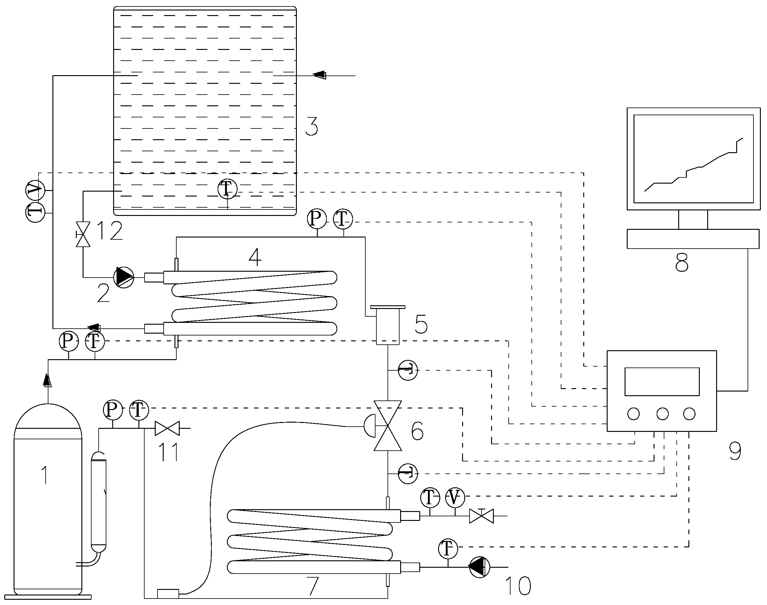
2. Description of System and Experimental Set-Up

2.1. Working Process of the WSHPWH System

A test rig designed for the WSHPWH system is schematized in Figure 1. The WSHPWH system is composed of a heat pump and data acquisition units, such as a compressor, evaporator, condenser, and expansion. Other parts, such as a data logger and a computer, are used to collect the experimental data.
The cyclic heating mode is used because it has a lower system capacity, requires less initial cost, and can supply plenty of water at once. The working process of the refrigerant can be described as follows. During the operation of the WSHPWH system, the refrigerant absorbs heat from the evaporator water, and is then compressed into high-pressure and temperature vapor. Afterwards, the refrigerant in the condenser transfers heat to the water in the water tank, and then passes through the thermal expansion valve (TXV). After throttling, the refrigerant of gas–liquid mixture with low temperature and low pressure in the evaporator absorbs heat from the water.

2.2. Experimental Facility and Procedures

An experimental device of the WSHPWH system was established, and Table 1 shows the detail specification of the main components.
In the experiments, the rated input power of the rotary-type hermetic compressor was 0.597 kW. To avoid overload, the suction and discharge temperatures and pressures of the compressor were monitored when the WSHPWH system was running, and overheated protector devices and low-high pressure cut-off switches were also set up. The evaporator and condenser was a double-pipe heat exchanger, and a TXV was installed downstream from the condenser. The experimental data were collected by a computer.
The water of the tank was heated after the WSHPWH system started. To assess the heating performance of this system, the water flux of the evaporator was adjusted to different values.

2.3. Error Analysis

A flow meter was used to measure the water fluxes of the evaporator and the condenser. Twelve platinum resistance thermometers (i.e., Pt100, with uncertainty of ±0.2 °C) were inserted in the measuring points of various equipment. Two piezoelectric pressure indicators (with an uncertainty of ±0.1 Mpa) were inserted in the suction and discharge pipes of the compressor. All of the data were recorded by a patrol monitor and stored in a computer, and the error of the data acquisition system can be ignored. The relative errors of the testing instruments for heating capacity and COP were 3.5% and 4%, respectively.

3. Data Analysis

A detailed thermal performance analysis was performed. Energy and exergy calculations of the systems were done as follows [16].
The COP for the WSHPWH system is:
COP = Q W = t 1 t 2 Q ( t ) d t t 1 t 2 w ( t ) d t
Exergy analysis of the WSHPWH system is based on the second law of thermodynamics; the exergy rate of the refrigerant or water is:
E x = q m ( h h 0 ) T 0 ( s s 0 )
The exergy efficiency of the WSHPWH system is calculated by:
ε = t 1 t 2 E h e a t d t t 1 t 2 W c o m p d t = t 1 t 2 E i n _ c o n d d t t 1 t 2 E o u t _ c o n d d t t 1 t 2 W c o m p d t
In order to optimize the WSHPWH system, the exergy efficiencies of compressor, condenser, and evaporator were the critical components that were calculated and analyzed.
The exergy efficiency of the compressor is calculated by:
ε c o m p = t 1 t 2 E r e _ c o m p _ o u t d t t 1 t 2 E r e _ c o m p _ i n d t t 1 t 2 W c o m p d t
The exergy efficiency of the condenser is calculated by:
ε c o n = t 1 t 2 E w _ con _ out d t t 1 t 2 E w _ c o n _ i n d t t 1 t 2 E r e _ con _ out d t t 1 t 2 E r e _ c o n _ i n d t
The exergy efficiency of the evaporator is calculated by:
ε e v a = t 1 t 2 E r e _ eva _ out d t t 1 t 2 E r e _ e v a _ i n d t t 1 t 2 E w _ eva _ out d t t 1 t 2 E w _ e v a _ i n d t

4. Results and Discussion

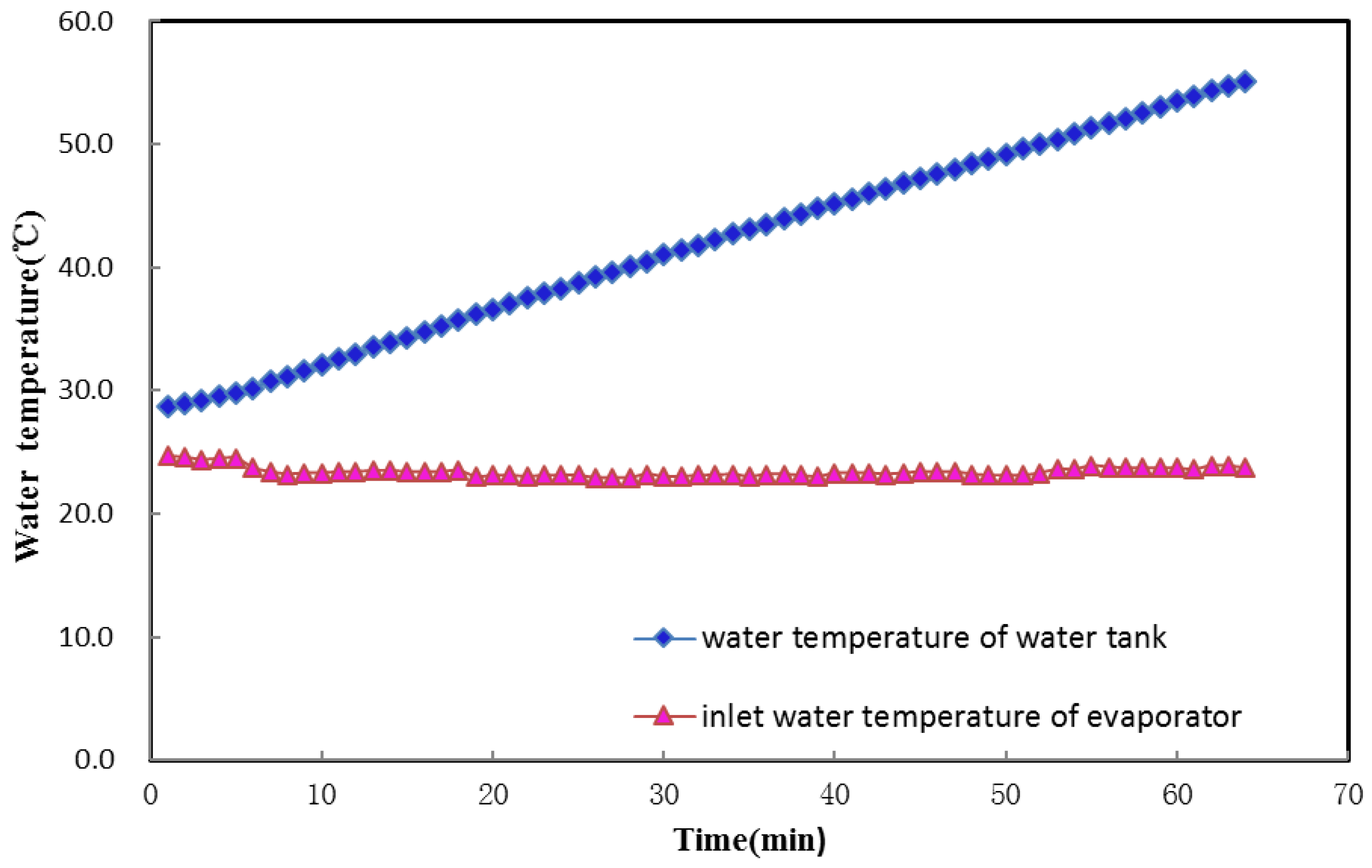
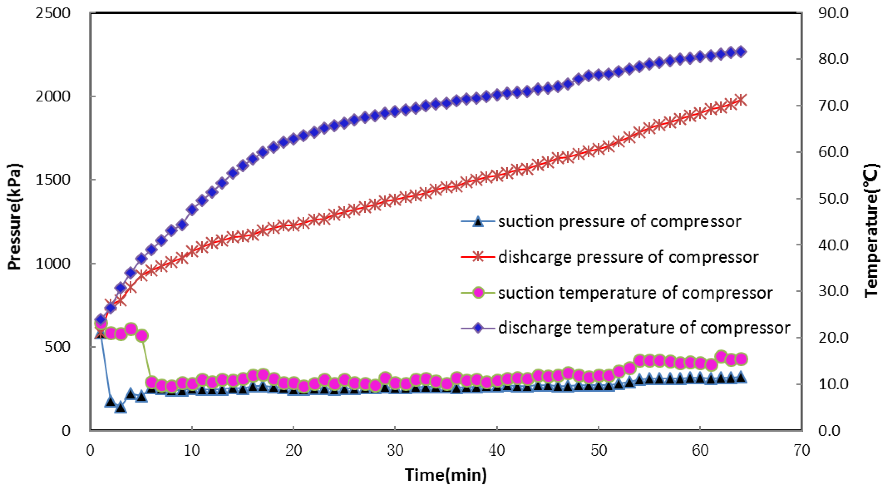
4.1. Heating Performance of the WSHPWH System

In order to explore the thermal performance of the WSHPWH system, a series of experiments were conducted under different conditions. Firstly, the heating performance was analyzed.
In this experiment, the water fluxes of the evaporator and condenser were set at 2.5 L/min and 14 L/min respectively, and the inlet water temperature of the evaporator was set at 23 °C. After the WSHPWH system started, 50 L of water was heated from 28 °C in the tank, and the experimental data were collected by the data logger. Meanwhile, the compressor suction pressure and temperature were monitored, which, when reached general maxima, stopped the system.
Figure 2 shows the variations of water temperature with the heating time. When the WSHPWH system ran for 64 min, 50 L of water was heated from 28 °C to 57 °C in the tank, indicating that the experimental prototype was capable of producing hot water. However, when the water temperature was beyond 55 °C, especially at around 57 °C, the compressor discharge pressure approached the general maximum (typically about 2.0 MPa) (Figure 3). If so, the compressor cannot run with long-term stability.
Figure 3 plots the changes of suction and discharge temperatures and pressures of the compressor with heating time. The suction temperature and pressure hardly changed after the system reached the steady-state. However, the discharge temperature and pressure gradually increased because of the cyclic heating mode. Finally, when 55 °C of hot water was obtained, the compressor discharge pressure rapidly rose, eventually reaching 2.0 MPa. This pressure approached the maximum, which had a negative effect on the compressor, and thus inevitably led to compressor and system instability.
As described above, the overly high compressor discharge pressure led to system instability when the water was heated to beyond 55 °C. Figure 4 shows the COP and power consumption variations with rising water temperature from 35 °C to 55 °C. The COP decreased with the rising water temperature, which was lowest (2.65) when the water was heated to 55 °C. However, the largest power consumption was 0.58 kW at this temperature. Therefore, the WSHPWH system had a higher COP and lower energy consumption when the water was heated to 50 °C. At this temperature, the energy consumption increased and the COP decreased. Thus, the temperature of water heated by the WSHPWH system should not exceed 55 °C.

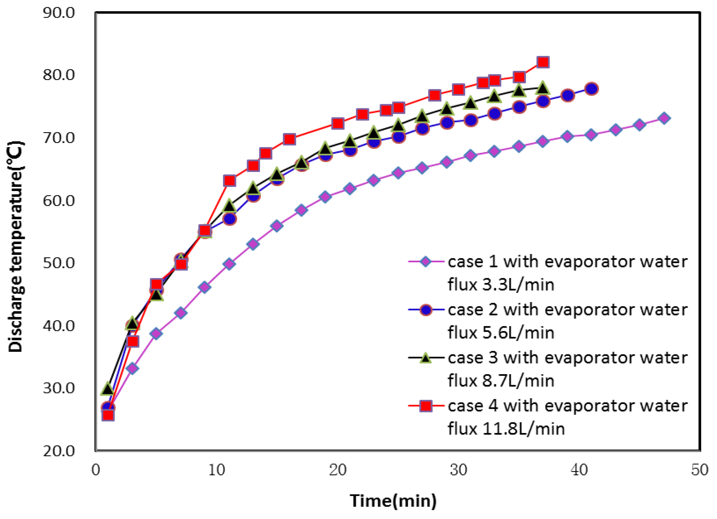
4.2. Effect of Water Flux of the Evaporator

The WSHPWH system absorbed heat from water, so its heat capacity was affected by water flux. In order to evaluate the effect of water flux on the heating performance of the system, four different water fluxes were used. Table 2 shows the system parameters of the WSHPWH system at different evaporator water fluxes.
In order to assess the effects of evaporator water flux on the heating performance of the WSHPWH system, the water temperatures at different water fluxes were detected. Figure 5 shows the variations of water temperature versus time. The heating time gradually decreased with the increasing evaporator water flux. The water temperature, which took 37 min to reach the set one when the evaporator water flux was 11.8 L/min, took 41 min to do so at 5.6 L/min. However, the water flux of case 4 was 2.1 times that of case 2, because the refrigerant filling quantity of the WSHPWH system was fixed. With increasing evaporator water flux, the heat absorbed by the refrigerant increased, and the heating time decreased. The evaporator inlet and outlet temperature differences fluctuated in a certain range due to the adjustment of the expansion valve and controlled heat that was absorbed from the water by the evaporator (Figure 6). Thus, the heating time of the system barely reduced with increasing evaporator water flux.
As discussed above, the heating time gradually decreased with increasing evaporator water flux. Nevertheless, when the evaporator water fluxes were 8.7 L/min and 11.8 L/min, the heating time remained the same. In order to evaluate the effects of evaporator water flux on heating time, different condenser tube side and shell side temperatures were used. Figure 7 and Figure 8 plot the condenser tube side and shell side temperature differences at different water fluxes, respectively. When the water temperature reached 50 °C, the condenser shell side temperature difference of case 4 was 32.4 °C, which was significantly higher than that of case 3 (28.6 °C). In contrast, the condenser water temperature difference of case 4 was 2.9 °C, which was slightly lower than that of case 3 (2.7 °C). Meanwhile, the water flux of the evaporator remained constant at different water fluxes of the condenser. Two different water fluxes had the same heating time. Accordingly, the condenser had inefficient heat transfer owing to the limited area, which cannot meet the requirements of the heat exchanger.
In order to research the effects of evaporator water flux on the compressor, the compressor discharge pressure and temperature were detected. Figure 9 and Figure 10 show the measured variation profiles of compressor discharge pressure and temperature at different evaporator water fluxes, respectively. The compressor discharge pressure and temperature rose with increasing heating time, and skyrocketed with rising evaporator water flux. This was due to the growing water flux as heat absorbed by the refrigerant gradually increased, which also continuously elevated the compressor discharge pressure and temperature. In addition, the maximum compressor discharge was 1900 kPa when the water flux was 11.8 L/min, which was close to the maximum discharge temperature of the compressor, thereby exerting a negative impact.
In order to keep the system working well, it is essential to unravel the effects of variations of evaporator water flux. As shown in Figure 11, the degree of superheat increases with the rising evaporator water flux. Especially, the degree of superheat was 17.5 °C when the evaporator water flux was 11.8 L/min. Figure 12 presents that the COP of case 4 is lowest, indicating that the system was inefficient at the evaporator water flux of 11.8 L/min. Considering heating time and system stability simultaneously, a favorable performance can be acquired when the evaporator water flux is 8.7 L/min.
Figure 13 shows the average exergy efficiencies of different evaporator water fluxes. Exergy efficiency refers to the ratio of all of the output effective exergy to the obtained effective exergy in a process. In general, a higher exergy efficiency represents a superior thermodynamics perfection. The exergy efficiency of case 3 was higher than those of the other cases. Since the exergy efficiency reached its minimum when the evaporator flux was 11.8 L/min, the system had a better performance in case 3 than in the others.
Figure 14 shows that the average exergy efficiency of the condenser is much lower than those of the compressor and evaporator at different evaporator water fluxes, suggesting that the condenser was inefficient in the WSHPWH system. In addition, all of the equipment had lower exergy efficiencies than those of the others when the evaporator water flux was 11.8 L/min, because the compressor suction pressure of case 4 was highest when 50 °C hot water was attained. As a result, the instantaneous compressor input power reached about 0.647 kW, resulting in larger exergy loss and lower exergy efficiency. For the condenser, the inlet and outlet temperature differences in case 4 were higher than those of the other cases. However, the condenser water inlet and outlet temperature difference remained 2.8 °C, leading to a lower exergy efficiency. The evaporator inlet and outlet temperature difference remained a certain value, so the heat capacity of the water increased with rising evaporator water flux, but that of the refrigerant still remained within a certain range due to the adjustment of the expansion valve, leading to larger exergy loss of the evaporator.

5. Conclusions

A series of experimental set-ups of the WSHPWH system were constructed and tested. The detailed conclusions are as follows:
(1)
The WSHPWH system took 64 min to heat 50 L of water in a water tank from an initial temperature of 28 °C to 57 °C in the cyclic heating mode. However, when the water temperature was beyond 55 °C, especially at around 57 °C, the compressor discharge pressure was close to the general maximum, leading to compressor and system unsteadiness. The COP of the system decreased and the energy consumption increased with rising water temperature. Consequently, the temperature of water heated by the WSHPWH system should not exceed 55 °C for a higher thermal COP and lower energy consumption, as well as stable and safe operation.
(2)
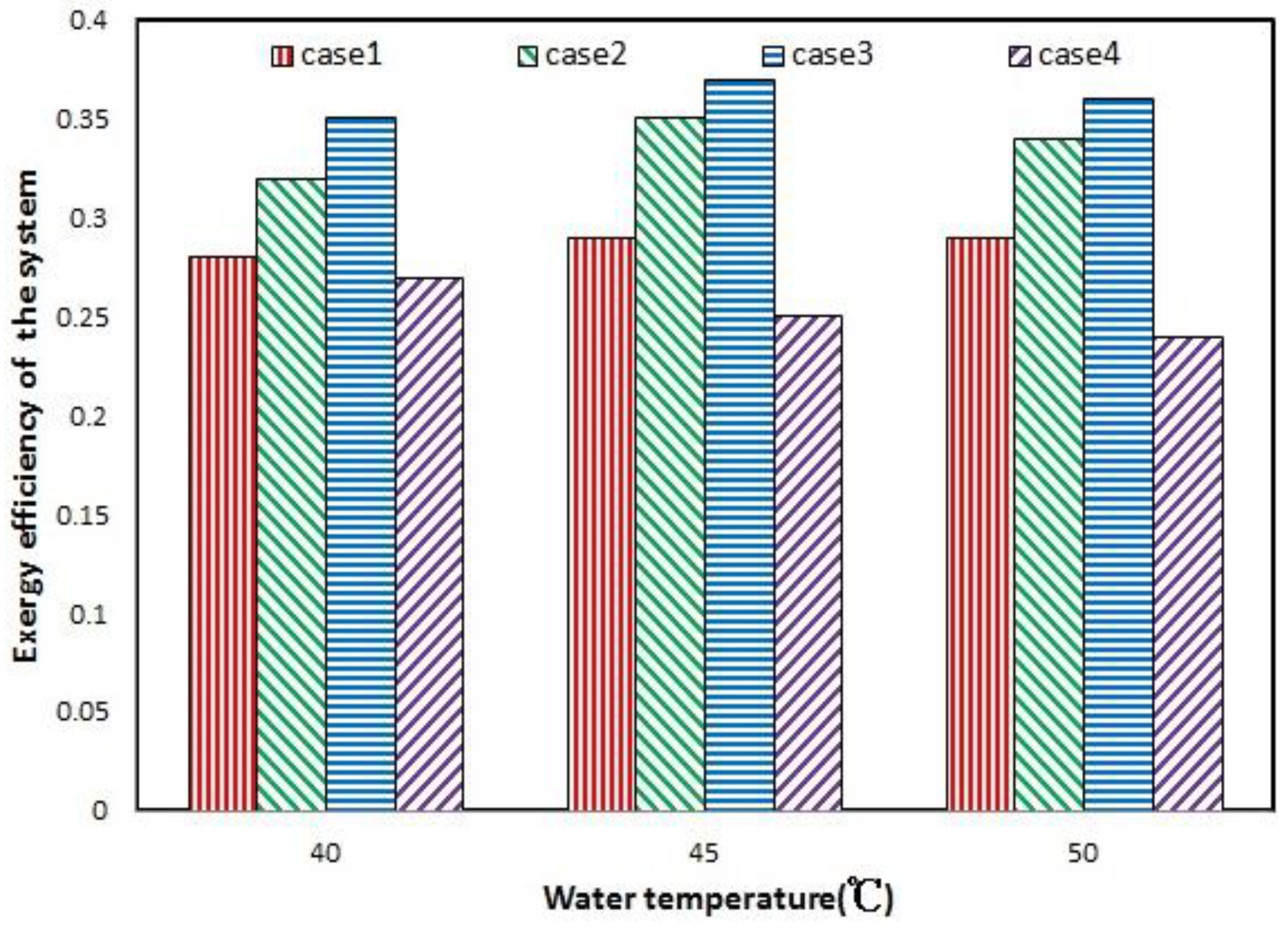
The performance parameters of the WSHPWH system were analyzed at different evaporator water fluxes. The heating time decreased as the evaporator water flux increased. However, the heating performance of the WSHPWH system was optimum when the evaporator water flux was 8.7 L/min. As suggested by the condenser shell and tube side temperature at different evaporator water fluxes, the condenser is inefficient.
(3)
When attaining the same temperature, the exergy efficiency of the condenser was lower than those of the other equipment. Thus, it is essential to reduce its energy destruction when the heating efficiency of the WSHPWH system is improved.

Author Contributions

All authors contributed to the paper. Z.Z. was the director of the research project, put forward the study ideas and wrote this paper; The data analysis and results interpreting was completed by Y.Z. and H.M.; Y.Z. and Y.Z. discussed experimental ideas and completed a part of the data analysis; the laboratory tests were completed by all authors.

Acknowledgments

The authors gratefully acknowledge that this work was supported by Jiangsu marine and fishery science and technology innovation and extension project (HY2017-8) and Zhenjiang funds for the key research and development project (GY2016002-1).

Conflicts of Interest

The authors declare no conflict of interest.

Nomenclature

COPcoefficient of performance
Qheating capacity (kW)
Wpower (kW)
Exexergy rate (kW)
qmmass flow rate (kg s−1)
hspecific enthalpy (kJ kg−1)
Sspecific entropy (kJ kg−1 K−1)
Ttemperature (K)
ttime (min)
Abbreviations
0environment state
compcompressor
condcondenser
ininlet
outoutlet
rerefrigerant
wWater
evaevaporator
εexergy efficiency
HPWHheat pump water heater
HPheat pump
SWHPseawater source heat pump
BWISbeach well infiltration intake system
HCHEhelical coil heat exchanger
WSHPWHwater-source heat pump water heater
TXVthermal expansion valve

References

  1. Willem, H.; Lin, Y.; Lekov, A. Review of energy efficiency and system performance of residential heat pump water heaters. Energy Build. 2017, 143, 191–201. [Google Scholar] [CrossRef]
  2. Congedo, P.M.; Colangelo, G.; Starace, G. Simulations of horizontal ground heat exchangers: A comparison among different configurations. Appl. Therm. Eng. 2012, 33–34, 24–32. [Google Scholar] [CrossRef]
  3. D’Arpa, S.; Petrosillo, I.; Uricchio, V.; Zurlini, G.; Colangelo, G.; Starace, G. heating requirements in greenhouses farming in South of Italy: Evaluation of Ground Source Heat Pump Utilization. J. Energy Effic. 2016, 9, 1065–1085. [Google Scholar] [CrossRef]
  4. Congedo, P.M.; Colangelo, G.; Starace, G. Horizontal Heat Exchangers for GSHP. Efficiency and Cost Investigation for Three Different Applications. In Proceedings of the ECOS2005-18th International Conference on Efficiency, Cost, Optimization, Simulation and Environment, Trondheim, Norway, 20–22 June 2005; pp. 1–8. [Google Scholar]
  5. Shapiro, C.; Puttagunta, S. Field Performance of Heat Pump Water Heaters in The Northeast; NREL: Golden, CO, USA, 2013. [Google Scholar]
  6. Han, S.K.; Chae, K.H.; Hwang, D.K. A design case study on sea and river water source heat pump. In Proceedings of the Society of Air-Conditioning and Refrigerating Engineers of Korea (SAREK) Summer Annual Conference, Pyeongchang, Korea, 6–8 July 2011; pp. 1212–1217. [Google Scholar]
  7. Zheng, W.D.; Zhang, H.; You, S.J.; Ye, T.Z. The Thermal Characteristics of a Helical Coil Heat Exchanger for Seawater-source Heat Pump in Cold Winter. Procedia Eng. 2016, 146, 549–558. [Google Scholar] [CrossRef]
  8. Zheng, W.D.; Ye, T.Z.; You, S.J.; Zhang, H. The thermal performance of seawater-source heat pump systems in areas of severe cold during winter. Energy Convers. Manag. 2015, 90, 166–174. [Google Scholar] [CrossRef]
  9. Baik, Y.J.; Kim, M.; Chang, K.C.; Lee, Y.S.; Ra, H.S. Potential to enhance performance of seawater-source heat pump by series operation. Renew. Energy 2014, 65, 236–244. [Google Scholar] [CrossRef]
  10. Shu, H.W.; Duanmu, L.; Shi, J.; Jia, X.; Ren, Z.Y.; Yu, H.Y. Field measurement and energy efficiency enhancement potential of a seawater source heat pump district heating system. Energy Build. 2015, 105, 352–357. [Google Scholar] [CrossRef]
  11. Zheng, X.J.; You, S.J.; Yang, J.; Chen, G.F. Seepage and heat transfer modeling on beach well infiltration intake system in seawater source heat pump. Energy Build. 2014, 68, 147–155. [Google Scholar] [CrossRef]
  12. Postrioti, L.; Baldinelli, G.; Bianchi, F.; Buitoni, G.; Di Maria, F.; Asdrubali, F. An experimental setup for the analysis of an energy recovery system from wastewater for heat pumps in civil buildings. Appl. Therm. Eng. 2016, 102, 961–971. [Google Scholar] [CrossRef]
  13. Araz, M.; Hepbasli, A.; Biyik, E.; Shahrestani, M.; Yao, R.; Essah, E.; Shao, L.; Oliveira, A.C.; Ekren, O.; Günerhan, H. Performance evaluation of a building integrated photovoltaic (BIPV) system combined with a wastewater source heat pump (WWSHP) system. Energy Procedia 2017, 140, 434–446. [Google Scholar] [CrossRef]
  14. Liu, X.; Ni, L.; Lau, S.K.; Li, H. Performance analysis of a multi-functional heat pump system in heating mode. Appl. Therm. Eng. 2013, 51, 698–710. [Google Scholar] [CrossRef]
  15. Wang, Y.; Ren, Y.; Gu, Y.; Meng, Q. Comparison and Analysis of Heat Transfer Enhancement for Wastewater Heat Exchanger in Wastewater Source Heat Pump System. Procedia Eng. 2017, 205, 2736–2743. [Google Scholar] [CrossRef]
  16. Pei, G.; Li, G.; Ji, J. Comparative study of air-source heat pump water heater systems using the instantaneous heating and cyclic heating modes. Appl. Therm. Eng. 2011, 31, 342–347. [Google Scholar]
Figure 1. System diagram of water-source heat pump water heater (WSHPWH) system. Key: T: thermocouples; P: pressure gauge; V: water flow meter. 1. Compressor, 2. Pump, 3. Water tank, 4. Condenser, 5. Filter, 6. Expansion valve, 7. Evaporator, 8. Computer, 9. Data logger, 10. Pump, 11. Filling valves, 12. Valve.
Energies 11 01205 g001
Figure 2. Variations of water temperature with heating time.
Energies 11 01205 g002
Figure 3. Variations of suction and discharge temperature and compressor pressure.
Energies 11 01205 g003
Figure 4. Coefficient of performance (COP) values and power consumptions of the WSHPWH system.
Energies 11 01205 g004
Figure 5. Variations of water temperature in the tank with heating time.
Energies 11 01205 g005
Figure 6. Evaporator inlet and outlet temperature differences with heating time.
Energies 11 01205 g006
Figure 7. Condenser inlet and outlet temperature differences of the refrigerant at different evaporator water fluxes.
Energies 11 01205 g007
Figure 8. Condenser inlet and outlet water temperature differences at different evaporator water fluxes.
Energies 11 01205 g008
Figure 9. Compressor discharge pressures at different evaporator water fluxes.
Energies 11 01205 g009
Figure 10. Compressor discharge temperatures at different evaporator water fluxes.
Energies 11 01205 g010
Figure 11. Degrees of compressor discharge superheat at different evaporator water fluxes.
Energies 11 01205 g011
Figure 12. COPs at different evaporator water fluxes.
Energies 11 01205 g012
Figure 13. Average exergy efficiencies of four different evaporator water fluxes.
Energies 11 01205 g013
Figure 14. Exergy efficiencies of main components.
Energies 11 01205 g014
Table 1. Specification of main components of the system. TXV: thermal expansion valve.
NameTypeRemarks
CompressorRotaryR134a, Rated input power: 0.597 kW, Displacement volume: 15.6 cm3/rev
CondenserDouble pipeCore diameter: 25 mm, Outer diameter: 32 mm, Length: 1.2 m
Expansion valveTXVExternal balanced type
EvaporatorDouble pipeCore diameter: 25 mm, Outer diameter: 32 mm, Length: 1.2 m
Water tankresistance150-L tank, thermal insulation material: polyurethane foaming plasticThermal insulation thickness: 50 mm
Table 2. System parameters at different evaporator water fluxes.
CaseEvaporator Water Flux (L/min)Condenser Water Flux (L/min)Evaporator Water Inlet Temperature (°C)Water Volume (L)Initial Temperature (°C)Set Temperature (°C)
Case 13.31423503050
Case 25.61423503050
Case 38.71423503050
Case 411.81423503050

