Article

A Robust Current Controller for Uncertain Permanent Magnet Synchronous Motors with a Performance Recovery Property for Electric Power Steering Applications

1
Department of Mechanical Engineering, Korea Advanced Institute of Science and Technology, Daejeon 291, Korea
2
Department of Creative Convergence Engineering, Hanbat National University, Daejeon 341-58, Korea
*
Authors to whom correspondence should be addressed.
Energies 2018, 11(5), 1224; https://doi.org/10.3390/en11051224
Submission received: 23 March 2018 / Revised: 3 May 2018 / Accepted: 7 May 2018 / Published: 10 May 2018
(This article belongs to the Special Issue Power Electronics 2018)

Abstract

:
This paper presents a robust current tracking controller for permanent magnet synchronous motors (PMSMs) with a performance recovery property for electric power steering (EPS) applications. The contributions of this work are twofold. First, a disturbance observer (DOB) is designed to compensate the disturbances arising from the model–plant mismatches while reducing the closed-loop sensitivity. Second, a current controller is designed to improve the current tracking performance in the frequency domain by assigning the performance recovery property to the closed-loop system. The closed-loop performance is verified through simulations and experiments using a 500 W PMSM connected to an EPS system.

1. Introduction

The permanent magnet synchronous motor (PMSM) has received widespread acceptance for use in precise industrial tasks for high-performance applications. For the electric actuation systems in vehicles in particular, PMSMs are extensively accepted due to their high efficiency, high power density, high precision, and low maintenance costs [1]. In particular, the electric power steering (EPS) system, which is a human assist device, is a device that assists the driver with steering torque, and PMSMs are mainly used in EPS systems for high-precision performance. Since 2010, most passenger cars have been produced using EPS systems to improve fuel economy and steering performance [2].
The current control of the individual motors affects the overall EPS performance and the upper EPS control logic. There have been many studies on the control logic of EPS generating a torque tracking command to create a comfortable steering sensation [2,3,4,5]. However, there have been relatively few attempts to enhance EPS performance by improving the performance of the motor torque controller.
A widespread current control scheme, the proportional integral (PI)-decoupling method, was introduced in [6], in which the scheme passes the closed-loop dynamics in the d-q frame through a corresponding first-order low-pass filter with a target cut-off frequency.
The controller directly compensates the nonlinear cross-coupling and back-electromotive force (EMF) terms relying on the rotor speed, and the remaining feedback linearized terms are controlled with pole-zero cancellation via the PI controller. However, this approach significantly depends on the motor parameters and speed measurement information, which can vary considerably according to the operating conditions. Therefore, closed-loop transient performance often deteriorates. This means that it is impractical to achieve acceptable closed-loop performance for a wide operating range.
Various studies aim to address the aforementioned problem. Parameter identification with adaptive control [7,8,9] in the control algorithm provides a good convergence characteristic; however, due to the convergence speed of each parameter, the control bandwidth is difficult to satisfy in actual applications that require a fast transient response. Another widespread method to guarantee robust performance, namely, the sliding mode control technique in [10,11,12,13], has great disturbance rejection performance, but the switching characteristics of the control input cause an excessive control action, resulting in the control system being overly sensitive. Despite its simplicity, direct torque control (DTC) [14,15,16,17] allows fast torque control performance in transient operating conditions. However, it is challenging to control flux and torque at very low speeds, and torque ripples and high currents continue to be difficult issues for human assist applications. Recently, model predictive control (MPC) has received widespread attention among many researchers due to the reduced burdens of its calculation [7,18,19,20,21,22]. Although MPC can guarantee the convergence to steady state, whether closed-loop optimality is preserved within PMSM uncertainty is questionable.
The internal model control (IMC) was reported as a robust current control scheme for AC machines. The relationship between synchronous-frame PI control and IMC was expressed in [23]. The paper revealed that integrators attached to the d q cross-coupling are effective for decoupling, and the implementation of IMC is the extension of applying a cross-coupling integrator. This study has influenced many important studies on PMSM current control [24,25,26]. Nevertheless, it is reported that this method requires accurate information on system parameters; otherwise, considerable oscillation may occur [27].
Recently, it has been reported that disturbance observer (DOB)-based control algorithms are effective in the current tracking problems of motor machines. DOB-based control schemes were proposed for DC/blushless DC (BLDC) motor control applications [28,29], robot manipulation [30], and PMSM current control applications [24,27,31,32,33].
Because of the simple add-on characteristics to the existing controller structure and its impressive disturbance rejection performance, this method is appropriate for applications that require a fast response. However, the studies are limited in the scope of performance improvement in the time domain for an individual motor device regardless of the load torque and speed variations.
This paper proposes a DOB-based robust current control method for uncertain PMSMs with transient performance recovery for EPS applications. The contributions of this work are divided into two parts. First, the paper illustrates the controller design method for improving the current tracking response in target frequency domains. The proposed DOB is designed to compensate only the disturbance of the target control region, and it does not make the system too sensitive. Second, the proposed control method is proven on a PMSM that is connected to the mechanical steering shaft of an actual vehicle, and the control response is recovered to achieve the desired performance when the torque load and motor speed change dynamically. The closed-loop performance is shown through simulations and using a 0.5 kW surface-mounted permanent magnet synchronous motor (SPMSM), and both time- and frequency-domain tracking performances are recovered.
Note that this paper is a generalized and detailed version of a conference paper [31]. In [31], only one design parameter is presented for convenience, however this paper takes into full consideration two design parameters of the controller. Analysis of the algorithms is suggested through time domain derivations of the proposed control and the frequency domain design guideline.

2. System Description

2.1. PMSM Control Issues in the EPS System

An EPS system assists the driver with the steering force and provides a comfortable steering sensation to the driver. In most cases, a PMSM is used as a torque assist actuator. Figure 1 illustrates the mechanical structure of an EPS system. The object of this system is to generate the motor torque T e to assist the driver with the steering torque T h to reach the steering angle θ 1 in the presence of an external torque T L caused by friction and self-aligning [2].
As shown in Figure 2, the EPS control system indirectly estimates the driver’s steering torque using a torque sensor placed between the steering wheel and the column [2]. To reduce the steering torque, the EPS control logic H generates the required motor torque T e , r e f , and the motor system G m generates torque T e to cancel out the external load torque T L . With some derivations, the transfer function to the internal system output ( θ 1 , θ 2 , T s ) from the external system input ( T h , T L ) is obtained as
θ 1 = P 1 + N P 2 H G m 1 + N P e q H G m T h + P 3 1 + N P e q H G m T L ,
θ 2 = P 4 + N P 5 H G m 1 + N P e q H G m T h + P 6 1 + N P e q H G m T L ,
T s = P 7 1 + N P e q H G m T h + P 8 1 + N P e q H G m T L ,
where P 1 P 8 and P e q are transfer functions with system parameters (the definition of each expression is in the Appendix A) and N is the constant gear ratio of the reduction gear. Note that the EPS control logic H and torque tracking transfer function G m are always connected in series H G m . The characteristic function of the transfer functions (1)–(3) is
1 + N P e q H G m = 0 .
The characteristic function determines the stability of the system; therefore, the tracking performance of G m is important, as is the design of H. In most cases, the design target of the torque controller of PMSM is
G m = T e T e , r e f = ω c c s + ω c c , s C ,
where ω c c is the desired torque tracking cut-off frequency. The crucial problem is that the desired performance (5) often deteriorates due to the existence of nonlinear disturbances and uncertainties in the PMSM system. Accordingly, it is very important to design a motor controller G m robust to disturbances and uncertainties for actual EPS applications.
Figure 3 represents the performance of a commercial EPS motor drive in the frequency domain. In the EPS system, the load torque T L and driver torque T h are produced irregularly and applied to the EPS logic H. However, as can be seen in [2], the effect of the load torque on the control logic sharply decreases above the resonance band over 11 Hz. Thus, in actual application, the torque controller is able to achieve the target performance (5) by suppressing disturbances below 20 Hz. In this regard, the proposed current controller is described in the next section.

2.2. PMSM Model in a Synchronous Rotating d-q Axis

The application of a rotating coordinate transformation ( d q -transformation) subject to the rotor position derivatives [6,32] is as follows:
d i d ( t ) d t = R s L d i d ( t ) + L q L d ω r ( t ) i q ( t ) + 1 L d u d ( t ) ,
d i q ( t ) d t = R s L q i q ( t ) L d L q ω r ( t ) i d ( t ) λ P M L q ω r ( t ) + 1 L q u q ( t ) ,
d ω ( t ) d t = B J ω ( t ) + 1 J T e ( i d ( t ) , i q ( t ) ) T L L ( t ) , t 0 ,
where i d ( t ) and i q ( t ) denote the d-q frame current. ω r ( t ) = P ω ( t ) denotes the electrical speed, with P and ω ( t ) representing the number of pole pairs and the mechanical speed, respectively. The PMSM parameters λ P M , B, J, L d , L q , and R s represent the magnetic flux, viscous friction, rotor inertia, d-q inductances, and stator resistance, respectively, with T L L ( t ) being the load torque to the rotor. The control inputs of u d ( t ) and u q ( t ) are the input voltages, and the generated torque T e ( i d ( t ) , i q ( t ) ) is given as
T e ( i d ( t ) , i q ( t ) ) = 3 2 P Δ L d q i d ( t ) i q ( t ) + λ P M i q ( t ) ,
t 0 , where Δ L d q = L d L q .
Except for the number of pole pairs P, the true values of the PMSM parameters are difficult to decisively identify due to the parameter varations under the operating conditions such as the PMSM temperature, gate driving condition, phase current, and DC link voltage. Additionally, the bandwidth of the rotor speed measurement is very low compared to the current dynamics, which also causes mismatches in the fast transient response. In this manner, it is natural to rearrange the current dynamics of (6) and (7) as
L x , 0 d i x ( t ) d t = R s , 0 i x ( t ) + v x ( t ) + u x ( t ) + f x ( t ) v d ( t ) = L q , 0 ω ˜ r ( t ) i q ( t ) v q ( t ) = L d , 0 ω ˜ r ( t ) i d ( t ) λ P M , 0 ω ˜ r ( t ) ,
where x = d , q , t 0 with the nominal parameters of R s , 0 , L d , 0 , L q , 0 , and λ P M , 0 . f x ( t ) represents the uncertainties and disturbances caused by the unmodeled dynamics and parameter mismatch; v x ( t ) , x = d , q , denote the calculated cross-coupling terms and back-EMF; and ω ˜ r ( t ) is the measurement of ω r ( t ) . The next section proposes the current controller design based on the perturbed dynamics of (10).

3. Controller Design

The control objective is to attain the transfer function of the closed-loop system as follows:
I x ( s ) I x , r e f ( s ) = ω c c s + ω c c , x = d , q , s C ,
where the design parameter ω c c denotes the desirable cut-off frequency, and I x ( s ) and I x , r e f ( s ) indicate the d-q frame current Laplace transforms, i x ( t ) , and the corresponding references, i x , r e f ( t ) , x = d , q , respectively. In the time domain, the target dynamics of (11) can be expressed as
i ˙ x ( t ) = ω c c i x , r e f ( t ) i x ( t ) , x = d , q , t 0 .

3.1. Problem: PI-Decoupling Method and Drawbacks

To achieve the tracking performance of (11), the conventional PI-decoupling method is widely and commonly used in industrial applications. This conventional controller is given by
u x ( t ) = u x , p i ( t ) v x ( t ) , x = d , q , t 0 ,
where u x , p i ( t ) , x = d , q , represent the PI controller outputs defined as
u x , p i ( t ) = K p , x e x ( t ) + K i , x e x ( t ) d t , x = d , q ,
t 0 , where K p , x = ω c c L x , 0 and K i , x = R s , 0 ω c c , x = d , q , denote the P and I gains of the controller, respectively, and tracking errors e x ( t ) , x = d , q , are defined as
e x ( t ) = i x , r e f ( t ) i x ( t ) , x = d , q , t 0 ,
The feature of the conventional controller is that the rotor speed coupling terms v x ( t ) , x = d , q , are directly compensated using nominal parameters and speed measurement, and the desired performance of (11) is obtained by the PI controller. Substituting the control laws of (13) into the d-q current dynamics of (10), it is derived that
i ˙ x ( t ) = ω c c i x , r e f ( t ) i x ( t ) + η x ( t )
η ˙ x ( t ) = R s , 0 L x , 0 η x ( t ) + 1 L x , 0 f ˙ x ( t ) , x = d , q ,
t 0 , where η x ( t ) means output disturbances to the current dynamics. Although the steady-state error converges to zero, the change of the disturbance f x ( t ) significantly affects the transient tracking dynamics. The problem is that the only way to reduce the effect of disturbances in this structure is to increase ω c c , which makes the system sensitive and susceptible to noise.

3.2. Proposed Control Algorithm

To address the disturbance rejection problem of the conventional method, a DOB-based control is proposed,
u x ( t ) = u x , p i ( t ) v x ( t ) f ^ x ( t ) , x = d , q ,
t 0 , where f ^ x ( t ) , x = d , q , represent the disturbance estimates defined as
f ^ x ( t ) = ζ x ( t ) + α x β x L x , 0 i x ( t ) , x = d , q , t 0 ,
and ζ x ( t ) , x = d , q , denote the states of the observers:
ζ ˙ x ( t ) = α x ζ x ( t ) α x 2 β x L x , 0 i x ( t ) + α x β x R s , 0 i x ( t ) u x , p i ( t ) ,
where α x and β x , x = d , q , denote the gains of the DOBs as design parameters, respectively. Henceforth, the observers of (19) with the outputs of (19) are called the DOBs. The structure of the proposed method is depicted in Figure 4.
Applying the control input designs of (18) and (19) into (10), the closed-loop current dynamics can be formed as
i ˙ x ( t ) = ω c c i x , r e f ( t ) i x ( t ) + η x ( t )
η ¨ x ( t ) = ( α x ( β x + 1 ) + R s , 0 L x , 0 ) η ˙ x ( t ) ( α x ( β x + 1 ) R s , 0 L x , 0 ) η x ( t ) + 1 L x , 0 f ¨ x ( t ) + α x L x , 0 f ˙ x ( t ) ,
Note that different disturbance rejection dynamics are induced in (22) compared to (17). The effect on disturbance f x ( t ) can be reduced by selecting design parameters α x and β x of the DOBs.
The next subsection guides the selection of the appropriate gains ( α x , β x ) of DOBs with physical meaning via frequency-domain analysis.

3.3. Control Gain Design Method in the Frequency Domain

To obtain the transfer function of the effect of the disturbance, taking Laplace transforms in (10) and (19)–(22) yields
Q x ( s ) = β x β x + 1 α x ( β x + 1 ) s + α x ( β x + 1 ) ,
M x ( s ) = s ( s + α x ) L x , 0 ( s + R s , 0 L x , 0 ) ( s + α x ( 1 + β x ) ) ( s + ω c c ) ,
S x ( s ) = L x , 0 α x β x + ω c c s + R s , 0 L x , 0 s + α x ( β x + 1 ) ω c c α x β x + ω c c s + α x ( 1 + β x ) s + ω c c ,
where transfer functions Q x ( s ) , M x ( s ) , and S x ( s ) , x = d , q , are the disturbance estimation function, the load disturbance sensitivity function, and the noise sensitivity function, respectively. The transfer functions are defined as
Q x ( s ) , M x ( s ) , S x ( s ) : = F ^ x ( s ) F x ( s ) , I x ( s ) F x ( s ) , U x ( s ) I x ( s )
where F x ( s ) , F ^ x ( s ) , I x ( s ) , and U x ( s ) denote the Laplace transforms of f x ( t ) , f ^ x ( t ) , i x ( t ) , and u x ( t ) , respectively. The frequency shapes of these transfer functions by changing a x and b x , x = d , q , determine the control performance.
Designing the parameters ( α x , β x ) separately has the advantages of having two degrees of freedom to adjust both the cut-off and DC gain of DOBs simultaneously. Figure 5 illustrates the attenuations in the frequency domain given the parameters α and β .
For simplicity, let ( · ) = ( · ) q in Figure 5. The electric parameters used in the magnitude plots of the transfer functions are designed as L = 198.9 e 6 H, R = 0.0315 Ω , and ω c c 2 π = 75 Hz for the ground case. Assume that the disturbances are distributed below 10 × 2 π rad/s. To obtain more disturbance attenuation, another PI-decoupling controller increases its gain to ω c c 2 π = 274.5 Hz. The PI controller with the increased gain provides an additional 11.3 dB of disturbance attenuation, but noise is amplified by 11.3 dB. Meanwhile, the proposed control method with ω c c 2 π = 10 Hz and β = 20 provides 26.4 dB of additional disturbance attenuation with the same noise amplification of 11.3 dB.
Remark 1.
Note that the disturbance attenuation in the target disturbance rejection frequency is reduced to 1 β + 1 below α [rad/s] by applying the proposed control method. Clearly, the proposed method has a great advantage in disturbance attenuation ability compared with the feedback linearization controller having the same noise amplification level.

4. Simulation Study

This section inspects the closed-loop performance of the proposed scheme compared with the PI-decoupling method in other works, such as feedback linearization (FL) in [6]. To achieve the simulation results, MATLAB SIMULINK 2016A (Mathworks, Natick, MA, USA) was utilized.

4.1. Simulation Environments: Electric Power Steering (EPS) System

The true electromagnetic parameters of the PMSM are given by
R s = 0.0229 Ω , L d = 198.9 uH , L q = 198.9 uH , λ P M = 0.1074 Wb , P = 3 ,
and the mechanical part is connected to the rotor shaft of the PMSM directly. The mechanical transfer function is given by
Ω ( s ) T e ( s ) = N 2 ( J 1 s 2 + C 1 s + K ) J 1 J 2 s 3 + ( J 1 C 2 + J 2 C 1 ) s 2 + ( J 1 + J 2 ) K s + ( C 1 + C 2 ) K
where T e ( s ) and Ω ( s ) are the Laplace transforms of the motor electrical torque T e ( i d ( t ) , i q ( t ) ) and the mechanical speed ω ( t ) , respectively. ( J 1 , J 2 , C 1 , C 2 , K, N) are the mechanical parameters given as
J 1 = 0.033 kgm 2 , J 2 = 0.085 kgm 2 , C 1 = 0.23 Nm / rad / s , C 2 = 2.4 Nm / rad / s , K = 143.24 Nm , N = 20.5
The mechanical system of (28) and (29) represents the mechanical system of EPS, which is depicted in Figure 1. The entire system combined with the mechanical system of (28) and (29) and the PMSM of (27) represent the EPS system of the target vehicle.
The DC-link voltage is given as V d c = 12 V for vehicle applications, and both the pulse-width modulation (PWM) and control frequencies are set as 20 kHz. The desired cut-off frequency is tuned as f c c = 75 Hz such that ω c c = 2 π f c c = 471 rad/s, which was applied to both the proposed method and the classical method. The simulations were conducted on two different uncertain cases: the first case is conducted under parameter variations, and the second case is simulating the current response under motor speed measurement delay. Both cases reveal major problems of the conventional method in practice; therefore, the proposed method aims to recover the current response under the uncertain environments in actual applications.

4.2. Simulation Case 1: Parameter Variations

For this simulation, to verify the robustness, the nominal parameters for the current controllers are perturbed to
R s , 0 = 0.5 R s , L d , 0 = 0.4 L d , L q , 0 = 0.5 L q , λ P M , 0 = 0.5 λ P M .
The first case simulation is performed to examine the closed-loop current tracking performance for three different DOB designs. The DOB design parameters for the proposed method were selected such that the set of ( α 2 π , β ) is { ( 10 Hz , 5 ) , ( 10 Hz , 20 ) , ( 100 Hz , 20 ) } . The simulation results of the closed-loop current responses are illustrated in Figure 6.
As expected, the proposed scheme recovers the ruined responses; however, values of α and β are too high amplify the noise of the control inputs, as shown in Figure 7. The simulation of the frequency response of Figure 8 provides more detailed information that ( α 2 π , β ) = ( 10 Hz , 20 ) and ( α 2 π , β ) = ( 100 Hz , 20 ) satisfy the tracking control performance. Considering tracking performance and noise amplification, ( α 2 π , β ) = ( 10 Hz , 20 ) certainly recovers the tracking performance of the classical method and shows acceptable noise sensitivity.

4.3. Simulation Case 2: Speed Measurement Delay

For this simulation case, it was assumed that the speed measurement is delayed without parameter variations. In many actual applications, the speed information is achieved by differentiating the position measurement; however, differentiating the raw signal severely amplifies digital and white noise, so the adaptation of a low-pass filter becomes necessary. Consequently, an inevitable delay occurs in the speed information because of the low-pass filtering. The measurement speed to control logic is
Ω ˜ r ( s ) = ω s s + ω s Ω r ( s ) , s C ,
where Ω ˜ r ( s ) is the Laplace transform of the measured electric speed ω ˜ r ( t ) , Ω r ( s ) is the Laplace transform of ω r ( t ) , and ω s is the cut-off of the speed measurement low-pass filter. In the simulation, ω s is set to 100 rad/s.
As shown in Figure 9 and Figure 10, the control performance degrades when a speed measurement delay exists. As expected, however, this method restores both the step response and the frequency response to the desired performance. Note that a situation with a very small time delay can be fatal to the transient response as there are large parameter uncertainties. This speed measurement delay can also be compensated by the proposed DOB-based method.

5. Experimental Results

In this section, the closed-loop performance of the proposed method is compared with conventional schemes, specifically FL, as presented in Section 3.1. The experiment was conducted using a 500 W SPMSM in an EPS system of a vehicle. The known parameters of the SPMSM were provided in the previous section. The control design parameters and the operating conditions were set to be consistent with those provided in the simulation section except for the design parameter α x to achieve an improved tracking performance. The proposed current control laws were implemented in a TMS320F28377D digital signal processor (DSP). Figure 11 and Figure 12 illustrate the configurations of the hardware setup and closed-loop system.

5.1. Experiment 1: Performance Recovery of the Proposed Method
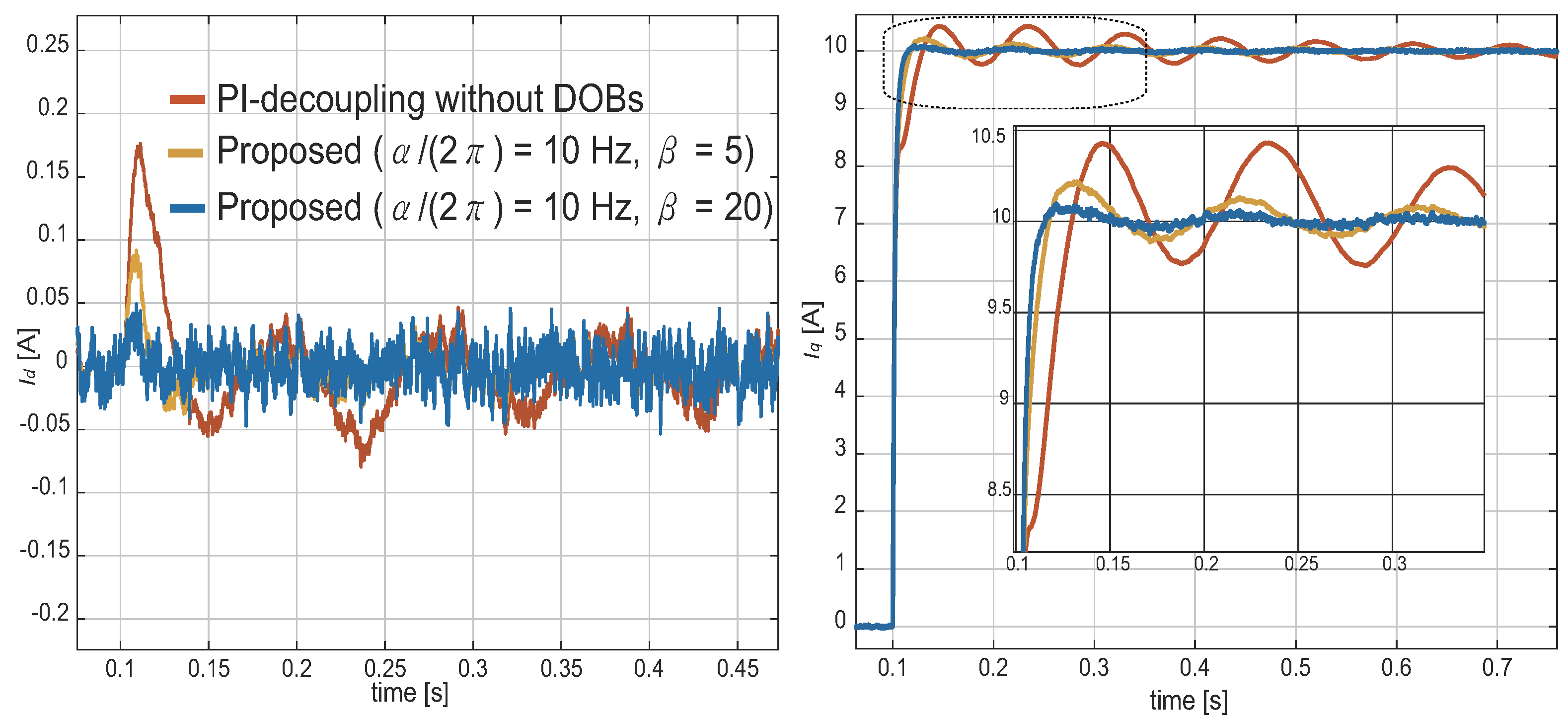
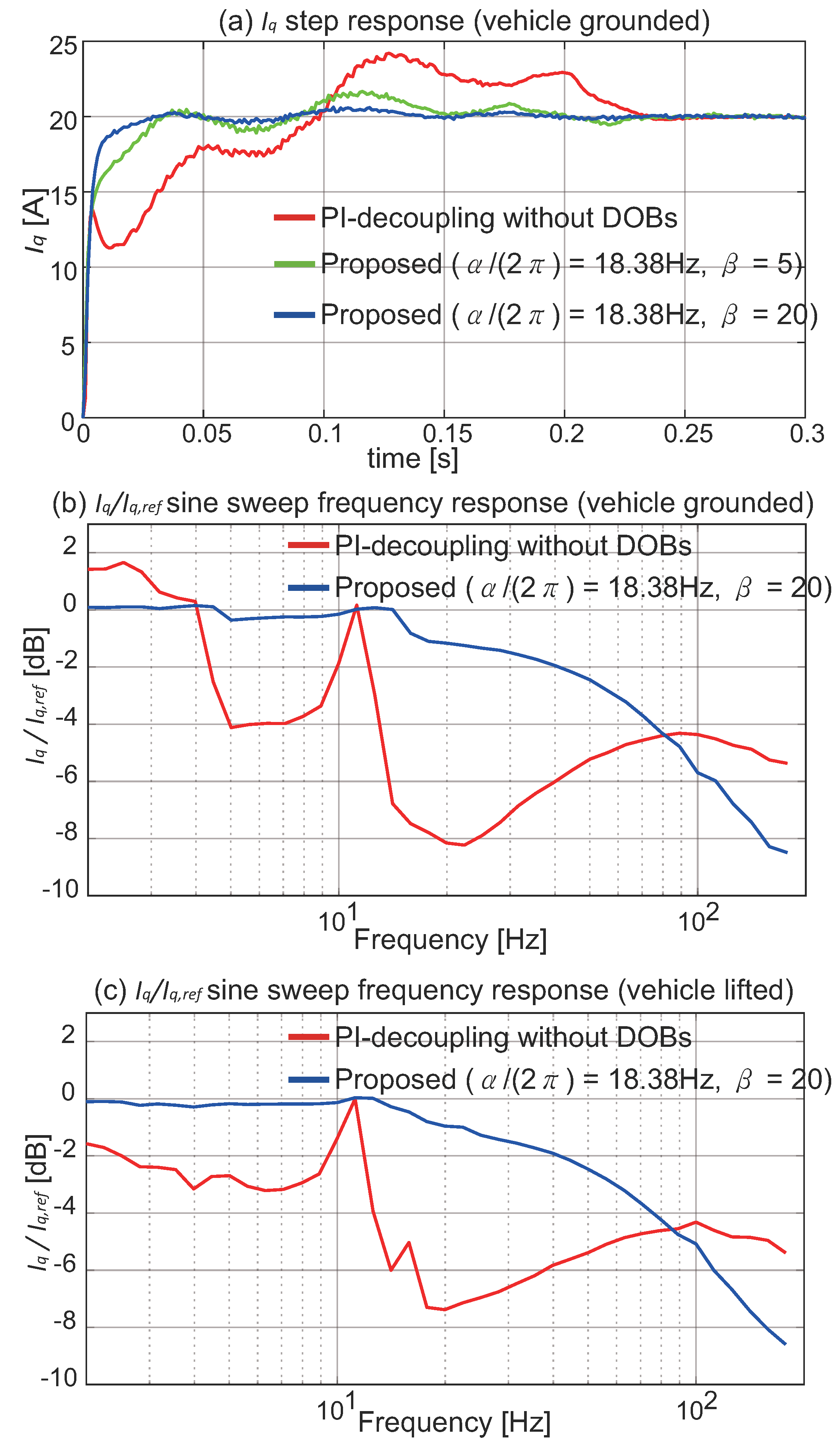
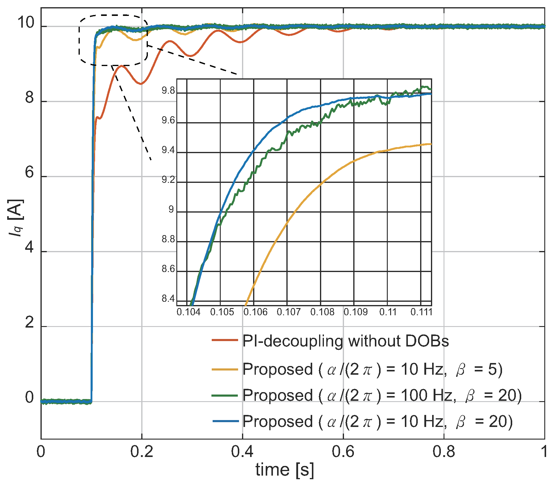
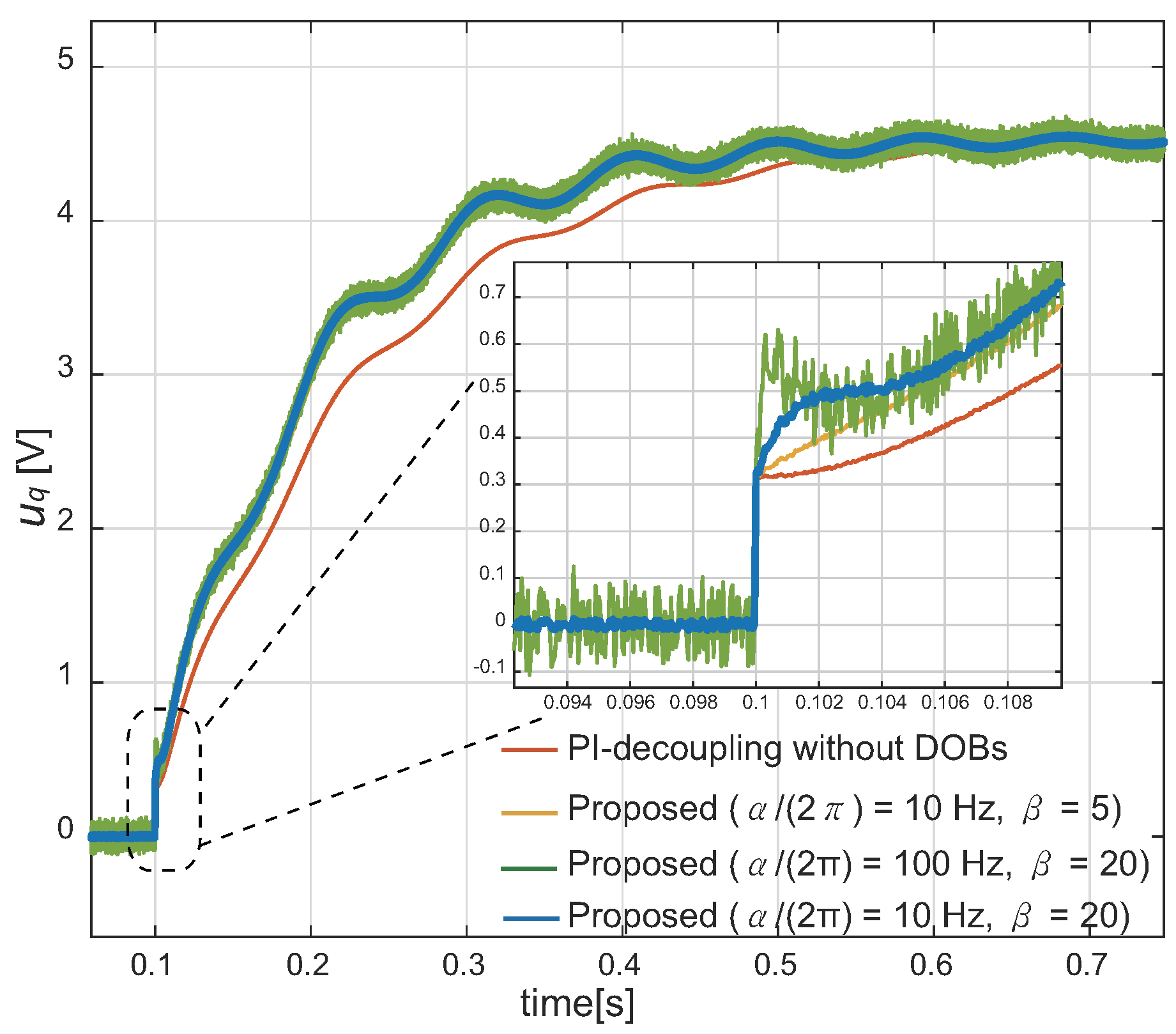
Three different experiments were performed to examine the performance of the proposed control method.
  • Experiment 1.1 ( i q , r e f = 20 A step reference input at t = 0 s):
    • In the first experiment, the test vehicle is on the ground, with high friction between the surface of the ground and the tyre. The result in Figure 13a indicates that an increase in the β gain and appropriate α effectively mitigate lumped disturbances and uncertainties, and the q-axis current recovers to the step response.
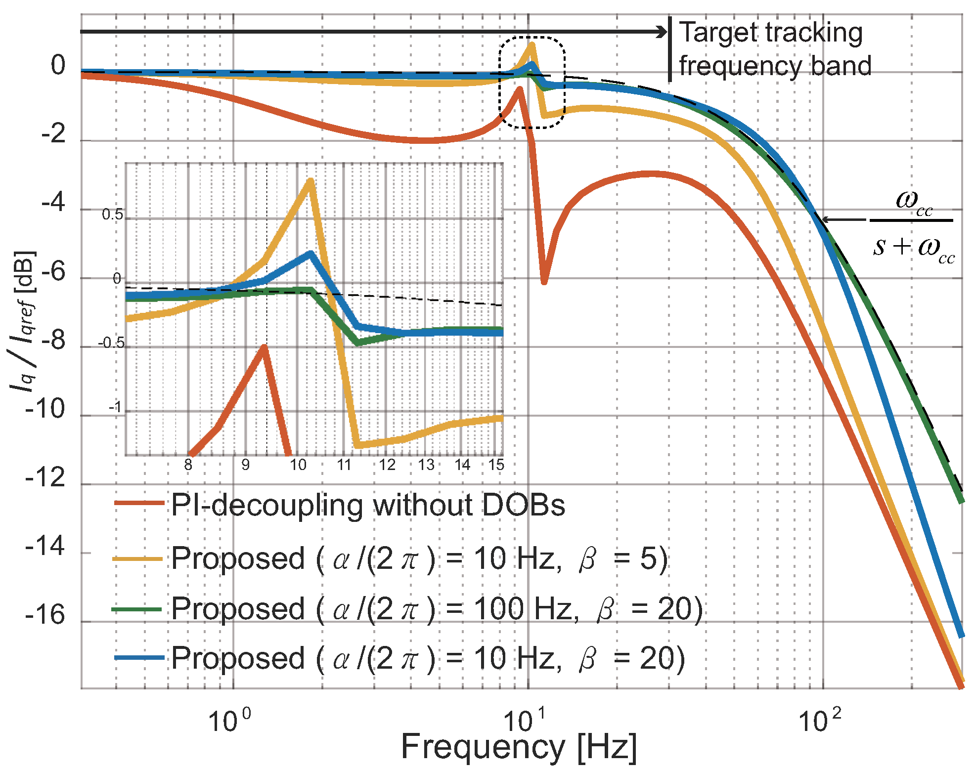
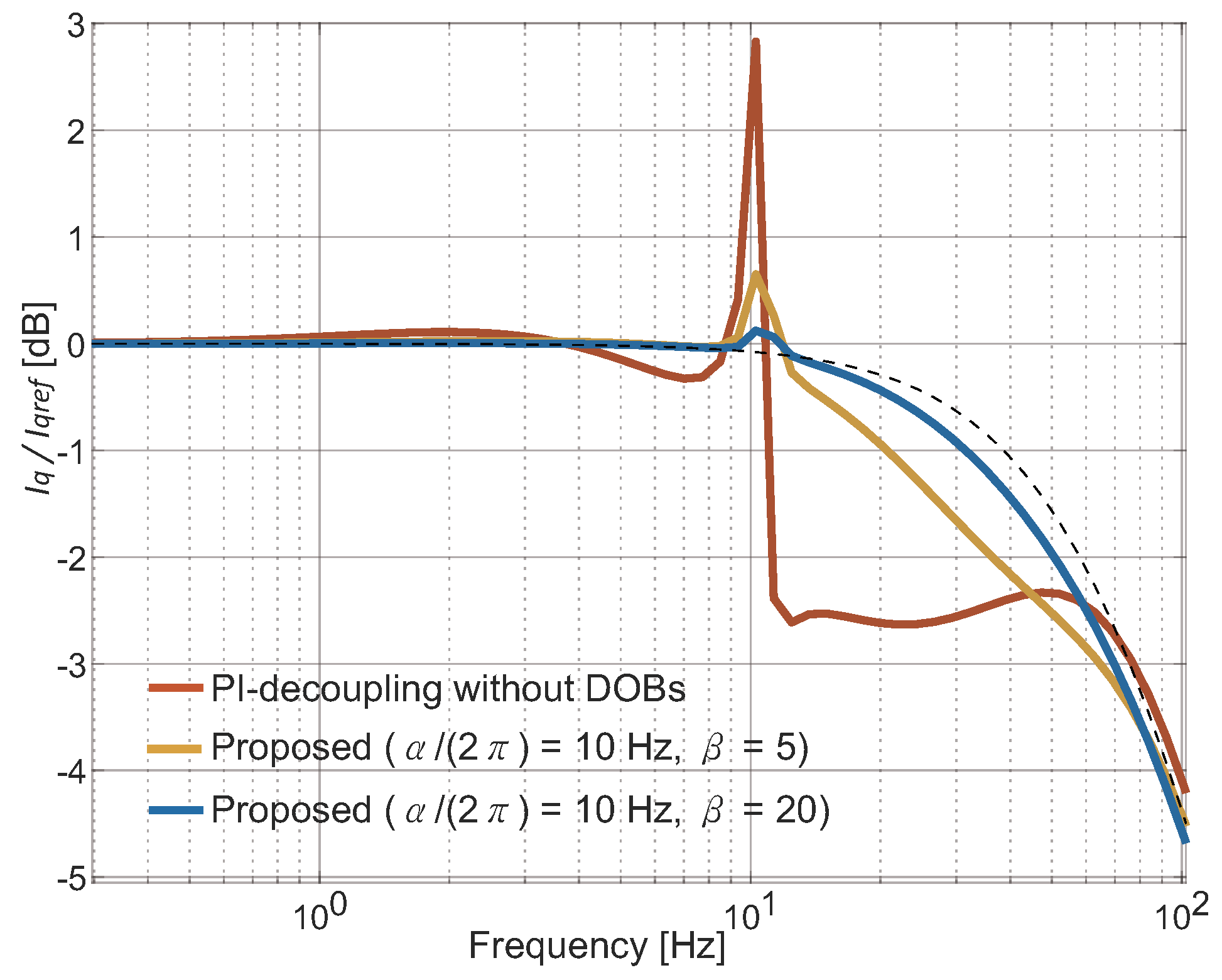
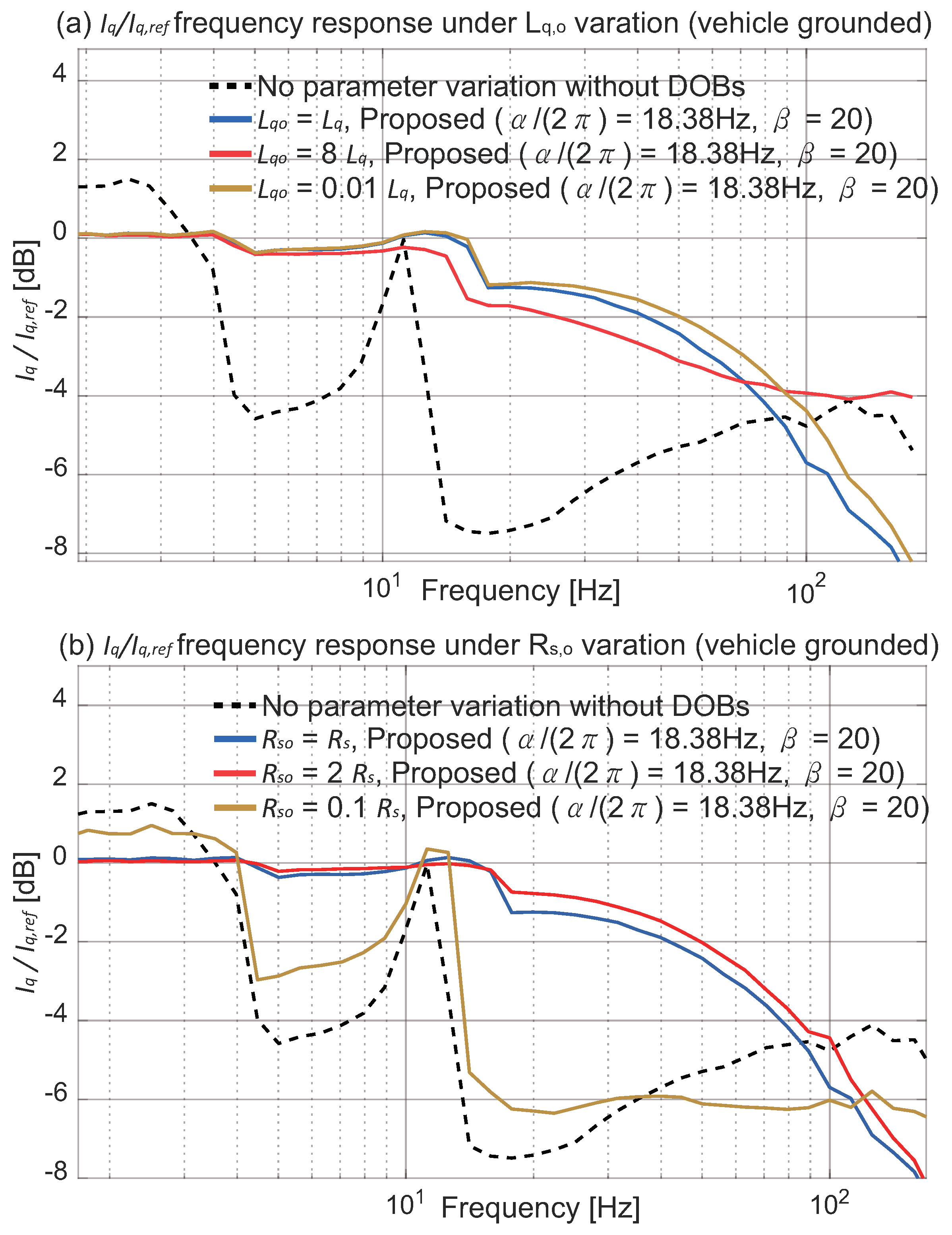
  • Experiment 1.2 and 1.3 (the sine sweeps when the vehicle is on the ground and lifted, respectively):
    • The sine sweeps are conducted with a +/−10 A amplitude continuous sinusoidal signal on the q-axis current reference i q , r e f with a set of discrete frequencies varying from 0 to 150 Hz. Figure 13b,c display the frequency response of i q / i q * ; both the measured current and reference are filtered with a 10th-order 300 Hz cut-off finite impulse response (FIR) filter to reject the effects of high-frequency noise from the measurement. Figure 13b,c prove that the effects of the disturbances, including the back-EMF, are well mitigated compared to the classical FL method. The compensation results recover to the frequency shape of the first-order low-pass filter. The difference between Figure 13b,c arises from different torque loads from the surface friction between the tyre and floor.

5.2. Experiment 2: Robust Stability to Parameter Variation

Two different experiments are conducted to examine the robustness of the proposed control method. In these experiments, the nominal parameter values used in the controller design are forcibly changed for the purpose of testing parameter uncertainty.
Figure 14a is the sine sweep experiment result for examining the effect of the uncertainty of q-axis inductance when the proposed method is applied. This result shows that the performance is recovered and maintained. Although slight changes occur compared to L q o = L q , the performance is not significantly decreased in the target frequency band (<20 Hz).
Figure 14b is the sine sweep experiment result for verifying the effect of the uncertainty of stator resistance when the proposed method is applied. This result indicates that the robustness does not break except for the case of 0.1 R q . The exception occurred because the I control gain of the PI controller is decreased one-tenth; equivalently, it has the same effect as a one-tenth reduction of β . However, in actual applications, the change of parameter R s is physically limited because the temperature of the machine is bounded.

6. Conclusions

The proposed algorithm provides the transient performance recovery property by introducing DOBs in EPS applications. The findings prove that the designed closed-loop system achieves sufficient current tracking performance for various uncertainties. The proposed method is clearly effective and considered to be a better alternative to the classical FL (PI-decoupling) method with a practical controller design approach. The following points are presented in this paper:
  • We examine and raise the problem of basic FL control widely used in EPS systems.
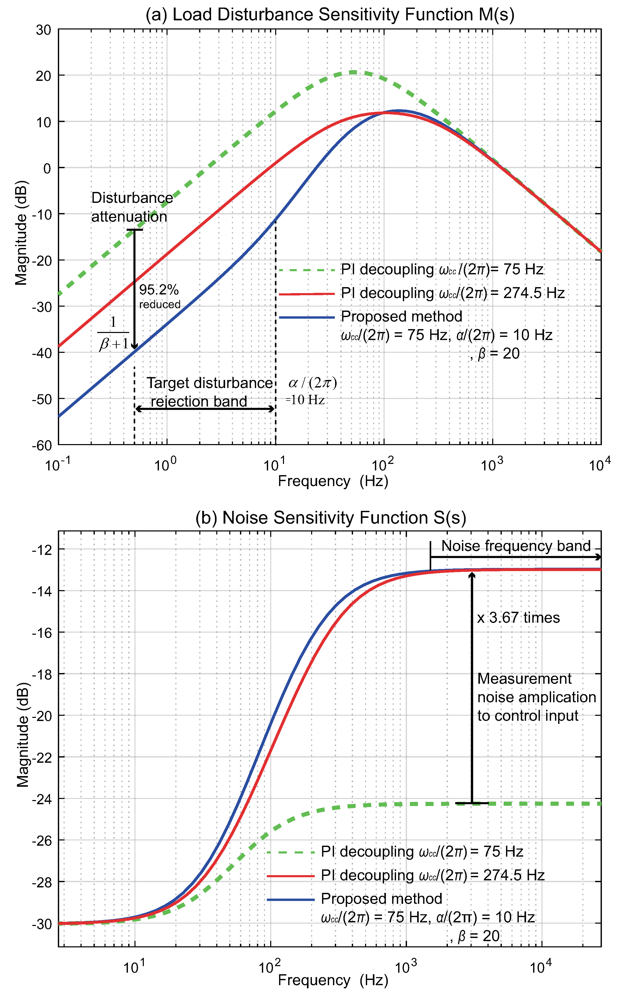
  • To solve the problem, this paper proposed a disturbance-observer-based current controller. The structure of the proposed controller is easy to design and has minimal influence on noise while greatly suppressing disturbances below 20 Hz from external load torques.
  • In an actual mechanical EPS system in a vehicle, the performance around the resonance point was recovered, and the robustness was proved in both simulations and experiments.
However, there is room for more detailed considerations on frequency shaping of disturbance attenuation in the proposed form. In addition, research on using the EPS logic controller H to design the PMSM controller G m is a challenging but important issue. Thus, it will be methodically verified in a future study.

7. Patents

“Motor control system and method for compensating disturbance,” US Patent App. 15/283,076, 2017. (USA, CHINA): https://patents.google.com/patent/US20170110992A1/en.

Author Contributions

The research study was carried out successfully with contribution from all authors. The main research idea, simulation works, experiments, and manuscript preparation were contributed by Y.K. H.-T.S. contributed to the manuscript preparation and idea development. S.-K.K. contributed theoretically on finalizing the research work and manuscript. K.-S.K. contributed and guided the overall flow of the research.

Acknowledgments

This research was supported by BK21 Plus Program. This research was also supported in part by Hyundai Motors Group as a part of Hyundai-KAIST cooperative research program.

Conflicts of Interest

The authors declare no conflict of interest.

Abbreviations

The following abbreviations are used in this manuscript:
PMSMPermanent Magnet Synchronous Motor
DOBDisturbance Observer
EPSElectric Power Steering
DTCDirect Torque Control
MPCModel Predictive Control
IMC Internal Model Control
FLFeedback Linearization

Appendix A. Transfer Functions of EPS Control System

The transfer functions of P 1 P 8 and P e q are given as
d o m = J 1 J 2 s 4 + ( J 1 C 2 + J 2 C 1 ) s 3 + ( C 1 C 2 + J 1 K + J 2 K ) s 2 + ( C 1 K + C 2 K ) s P e q , P 8 = K ( J 1 s 2 + C 1 s ) / d o m P 1 = ( J 2 s 2 + C 2 s + K ) / d o m P 2 , P 3 , P 4 , P 5 = K / d o m P 6 = ( J 1 s 2 + C 1 s + K ) / d o m P 7 = K ( J 2 s 2 + C 2 s ) / d o m

References

  1. Cheng, M.; Sun, L.; Buja, G.; Song, L.; Zhou, K. Advanced electrical machines and machine-based systems for electric and hybrid vehicles. Energies 2015, 9, 9541–9564. [Google Scholar] [CrossRef]
  2. Lee, D.; Kim, K.S.; Kim, S. Controller design of an electric power steering system. IEEE Trans. Control Syst. Technol. 2017, 2, 748–755. [Google Scholar] [CrossRef]
  3. Chen, X.; Yang, T.; Chen, X.; Zhou, K. A generic model-based advanced control of electric power-assisted steering systems. IEEE Trans. Control Syst. Technol. 2008, 6, 1289–1300. [Google Scholar] [CrossRef]
  4. Marouf, A.; Djemai, M.; Sentouh, C.; Pudlo, P. A new control strategy of an electric-power-assisted steering system. IEEE Trans. Veh. Technol. 2012, 8, 3574–3589. [Google Scholar] [CrossRef]
  5. Hung, Y.C.; Lin, F.J.; Hwang, J.C.; Chang, J.K.; Ruan, K.C. Wavelet fuzzy neural network with asymmetric membership function controller for electric power steering system via improved differential evolution. IEEE Trans. Power Electron. 2015, 4, 2350–2362. [Google Scholar] [CrossRef]
  6. Sul, S.-K. Control of Electric Machine Drive Systems; John Wiley and Sons: Hoboken, NJ, USA, 2011. [Google Scholar]
  7. Perez, J.H.; Hernandez, O.S.; Caporal, R.M.; de JR Magdaleno, J.; Barreto, H.P. Parameter Identification of a Permanent Magnet Synchronous Machine based on Current Decay Test and Particle Swarm Optimization. IEEE Latin Am. Trans. 2013, 5, 1176–1181. [Google Scholar] [CrossRef]
  8. Gan, C.; Wu, J.; Hu, Y.; Yang, S.; Cao, W.; Kirtley, J.L. Online sensorless position estimation for switched reluctance motors using one current sensor. IEEE Trans. Power Electron. 2016, 10, 7248–7263. [Google Scholar] [CrossRef]
  9. Zhao, L.; Huang, J.; Chen, J.; Ye, M. A parallel speed and rotor time constant identification scheme for indirect field oriented induction motor drives. IEEE Trans. Power Electron. 2016, 9, 6494–6503. [Google Scholar] [CrossRef]
  10. Utkin, V.; Guldner, J.; Shi, J. Sliding Mode Control in Electromechanical Systems; CRC Press: Boca Raton, FL, USA, 2017. [Google Scholar]
  11. Chang, S.H.; Chen, P.Y.; Ting, Y.H.; Hung, S.W. Robust current control-based sliding mode control with simple uncertainties estimation in permanent magnet synchronous motor drive systems. IET Electr. Power Appl. 2010, 6, 441–450. [Google Scholar] [CrossRef]
  12. Jezernik, K.; Korelič, J.; Horvat, R. PMSM sliding mode FPGA-based control for torque ripple reduction. IEEE Trans. Power Electron. 2013, 7, 3549–3556. [Google Scholar] [CrossRef]
  13. Repecho, V.; Biel, D.; Arias, A. Fixed Switching Period Discrete-Time Sliding Mode Current Control of a PMSM. IEEE Trans. Ind. Electron. 2018, 3, 2039–2048. [Google Scholar] [CrossRef]
  14. Zhong, L.; Rahman, M.F.; Hu, W.Y.; Lim, K.W. Analysis of direct torque control in permanent magnet synchronous motor drives. IEEE Trans. Power Electron. 1997, 3, 528–536. [Google Scholar] [CrossRef]
  15. Xia, C.; Zhao, J.; Yan, Y.; Shi, T. A novel direct torque control of matrix converter-fed PMSM drives using duty cycle control for torque ripple reduction. IEEE Trans. Ind. Electron. 2014, 6, 2700–2713. [Google Scholar] [CrossRef]
  16. Niu, F.; Wang, B.; Babel, A.S.; Li, K.; Strangas, E.G. Comparative evaluation of direct torque control strategies for permanent magnet synchronous machines. IEEE Trans. Power Electron. 2016, 2, 1408–1424. [Google Scholar] [CrossRef]
  17. Song, Q.; Li, Y.; Jia, C. A Novel Direct Torque Control Method Based on Asymmetric Boundary Layer Sliding Mode Control for PMSM. Energies 2018, 3, 657. [Google Scholar] [CrossRef]
  18. Geyer, T.; Papafotiou, G. Model predictive direct torque control—Part I: Concept, algorithm, and analysis. IEEE Trans. Ind. Electron. 2009, 6, 1894–1905. [Google Scholar] [CrossRef]
  19. Papafotiou, G.; Kley, J.; Papadopoulos, K.G.; Bohren, P.; Morari, M. Model predictive direct torque control-part II: implementation and experimental evaluation. IEEE Trans. Ind. Electron. 2009, 6, 1906–1915. [Google Scholar] [CrossRef]
  20. Yang, N.; Li, D.; Zhang, J.; Xi, Y. Model predictive controller design and implementation on FPGA with application to motor servo system. Control Eng. Pract. 2012, 11, 1229–1235. [Google Scholar] [CrossRef]
  21. Chai, S.; Wang, L.; Rogers, E. Model predictive control of a permanent magnet synchronous motor with experimental validation. Control Eng. Pract. 2013, 11, 1584–1593. [Google Scholar] [CrossRef]
  22. Jin, N.; Guo, L.; Yao, G. Model Predictive Direct Power Control for Nonredundant Fault Tolerant Grid-Connected Bidirectional Voltage Source Converter. Energies 2018, 8, 1133. [Google Scholar] [CrossRef]
  23. Harnefors, L.; Nee, H.P. Model-based current control of AC machines using the internal model control method. IEEE Trans. Ind. Appl. 1998, 1, 133–141. [Google Scholar] [CrossRef]
  24. Mohamed, Y.A.R.I. Design and implementation of a robust current-control scheme for a PMSM vector drive with a simple adaptive disturbance observer. IEEE Trans. Ind. Electron. 2007, 4, 1981–1988. [Google Scholar] [CrossRef]
  25. Briz, F.; Degner, M.W.; Lorenz, R.D. Analysis and design of current regulators using complex vectors. IEEE Trans. Ind. Appl. 2000, 3, 817–825. [Google Scholar] [CrossRef]
  26. Kim, H.; Degner, M.W.; Guerrero, J.M.; Briz, F.; Lorenz, R.D. Discrete-time current regulator design for AC machine drives. IEEE Trans. Ind. Appl. 2010, 4, 1425–1435. [Google Scholar]
  27. Ren, J.; Ye, Y.; Xu, G.; Zhao, Q.; Zhu, M. Uncertainty-and-disturbance-estimator-based current control scheme for PMSM drives with a simple parameter tuning algorithm. IEEE Trans. Power Electron. 2017, 7, 5712–5722. [Google Scholar] [CrossRef]
  28. Son, Y.I.; Kim, I.H.; Choi, D.S.; Shim, H. Robust cascade control of electric motor drives using dual reduced-order PI observer. IEEE Trans. Ind. Electron. 2015, 6, 3672–3682. [Google Scholar] [CrossRef]
  29. Jo, N.H.; Jeon, C.; Shim, H. Noise reduction disturbance observer for disturbance attenuation and noise suppression. IEEE Trans. Ind. Electron. 2017, 2, 1381–1391. [Google Scholar] [CrossRef]
  30. Chen, W.H.; Ballance, D.J.; Gawthrop, P.J.; O’Reilly, J. A nonlinear disturbance observer for robotic manipulators. IEEE Trans. Ind. Electron. 2000, 4, 932–938. [Google Scholar] [CrossRef] [Green Version]
  31. Kim, Y.; Kim, K.S.; Kim, S. A novel disturbance observer based robust current-control for a PMSM drive system. In Proceedings of the 2015 IEEE 54th Annual Conference on Decision and Control (CDC), Osaka, Japan, 15–18 December 2015; pp. 6043–6046. [Google Scholar]
  32. Kim, S.K. Proportional-type performance recovery current tracking control algorithm for PMSM. IET Electr. Power Appl. 2017. [Google Scholar] [CrossRef]
  33. Ozsoy, E.; Padmanaban, S.; Mihet-Popa, L.; Fedák, V.; Ahmad, F.; Akhtar, R.; Sabanovic, A. Control strategy for a grid-connected inverter under unbalanced network conditions—A disturbance observer-based decoupled current approach. Energies 2018, 7, 1067. [Google Scholar] [CrossRef]
Figure 1. The picture and the schematic of the electric power steering (EPS) system. PMSM: permanent magnet synchronous motor.
Energies 11 01224 g001
Figure 2. A block diagram of an EPS system.
Energies 11 01224 g002
Figure 3. The performance degradation of the linearized feedback PI controller widely used in industry (a test on a commercial motor controller of an EPS system): (a) torque tracking performance degradation; (b) individual frequency tracking performances (added).
Energies 11 01224 g003
Figure 4. Proposed current control algorithm structure. DOB: disturbance observer.
Energies 11 01224 g004
Figure 5. Comparison of q-axis (a) load disturbance sensitivity and (b) noise sensitivity function.
Energies 11 01224 g005
Figure 6. The q-axis current ( i q ( t ) ) step responses under parameter variations.
Energies 11 01224 g006
Figure 7. The q-axis control input ( u q ( t ) ) under parameter variations.
Energies 11 01224 g007
Figure 8. The q-axis current tracking frequency response (sine sweep) under parameter variations.
Energies 11 01224 g008
Figure 9. The d- and q-axis current step responses under speed measurement delay due to the low-pass filter.
Energies 11 01224 g009
Figure 10. The d- and q-axis current frequency responses under speed measurement delay due to the low-pass filter.
Energies 11 01224 g010
Figure 11. Hardware setup.
Energies 11 01224 g011
Figure 12. Configuration of implemented closed-loop system [6].
Energies 11 01224 g012
Figure 13. Experiment 1: q-axis current responses (a,b) when the vehicle is on the ground; and (c) when the vehicle is lifted.
Energies 11 01224 g013
Figure 14. Experiment 2: q-axis current responses when there is (a) inductance parameter variation and (b) resistance parameter variation.
Energies 11 01224 g014

