Article

Co-Simulation of Smart Distribution Network Fault Management and Reconfiguration with LTE Communication

1
Department of Electrical and Electronic Engineering, University of Cagliari, Piazza d’Armi, 09123 Cagliari, Italy
2
Department of Information Security and Communication Technology, NTNU—Norwegian University of Science and Technology, O.S. Bragstads plass 2B, 7491 Trondheim, Norway
3
Ricerca sul Sistema Energetico—RSE S.p.A., via R. Rubattino 54, 20134 Milano, Italy
*
Author to whom correspondence should be addressed.
Energies 2018, 11(6), 1332; https://doi.org/10.3390/en11061332
Submission received: 17 April 2018 / Revised: 18 May 2018 / Accepted: 21 May 2018 / Published: 23 May 2018
(This article belongs to the Special Issue Methods and Concepts for Designing and Validating Smart Grid Systems)

Abstract

:
Transition towards a smart grid requires network modernization based on the deployment of information and communication technologies for managing network operation and coordinating distributed energy resources in distribution systems. The success of the most advanced smart grid functionalities depends on the availability and quality of communication systems. Amongst the most demanding functionalities, those related to fault isolation, location and system restoration (FLISR) to obtain a self-healing smart grid are critical and require low latency communication systems, particularly in case of application to weakly-meshed operated networks. Simulation tools capable of capturing the interaction between communication and electrical systems are of outmost utility to check proper functioning of FLISR under different utilization conditions, to assess the expected improvements of Quality of Service, and to define minimum requirements of the communication system. In this context, this paper investigates the use of public mobile telecommunication system 4G Long Term Evolution (LTE) for FLISR applications in both radially and weakly-meshed medium voltage (MV) distribution networks. This study makes use of a co-simulation software platform capable to consider power system dynamics. The results demonstrate that LTE can be used as communication medium for advanced fault location, extinction, and network reconfiguration in distribution networks. Furthermore, this paper shows that the reduction of performances with mobile background usage does not affect the system and does not cause delays higher than 100 ms, which is the maximum allowable for power system protections.

1. Introduction

1.1. Motivation

The development of future energy systems in accordance with the smart grid (SG) paradigm requires a radical change in the management of the electricity distribution network, which needs to become intelligent and adaptive. Smart distribution networks (SDN) have systems in place to control a combination of distributed energy resources (DERs). Distribution system operators (DSOs) have the possibility of managing electricity flows using a flexible network topology [1,2]. The transition towards SDN involves software, automation, and controls to ensure that the power distribution network, not only remains within its operating limits (e.g., node voltages and branch currents within acceptable limits), but is also operated in an optimal way. In the SDN context, therefore, Information and Communication Technologies (ICT) are not a simple add-on to the electrical system, but their availability and efficiency are essential for operating the entire power distribution system. In fact, the electric system is managed and controlled through ICT network, which allows a bidirectional exchange of large amounts of data, creating a keen interdependence between electric system and ICT system. In the ICT system, the communication between the SDN components is characterized by non-idealities such as latencies and packet losses that may reflect upon the power system operation; furthermore, components such as antennas, routers, modems, etc. are subjected to faults and malfunctioning that may cause system reliability reduction or service interruption [3].
In this context, this article aims at providing—by means of a co-simulation-based assessment method—an evaluation of the performance of LTE as communication technology for smart grid application, considering a highly time-critical application like fault location, isolation and system reconfiguration (FLISR).

1.2. Literature Review on Simulation of Communication Systems for Smart Grids

With recent enhancements in wireless solutions, which guarantee a reliable low-cost communication, a strong interest is upon the possibility of exploiting last generation communication systems for supporting the transition of distribution network towards a Smart Grid scenario. However, the best option for communication technology solution to fit SG applications is still not clear, even though LTE technology is considered one of the most promising. LTE, with its widespread distribution, broad coverage, high throughput, device-to-device (D2D) capability, despite not being originally designed for smart grid applications, represents a valuable candidate for usage in a SG communication system [4,5]. A comprehensive analysis of an LTE-based smart grid operation analysis with a co-simulation approach is still missing in literature. In [6], the communication challenges when choosing a technology supporting distribution automation applications was investigated with the communication software OPNET. LTE performances were analyzed in terms of coverage, delay and reliability with variable real-world deployment constraints, but the impact on distribution network was only analyzed in terms of requirements, and no interrelation between communication network and distribution network was analyzed in a joint way. A similar approach was adopted in Reference [7], where OPNET simulated using LTE for transmitting Phase Measurement Unit (PMU) packets in a fault monitoring system. Performances in terms of latencies, channel utilization, and response with variable load were examined. An analogous methodology was applied in [8], where LTE was analyzed in an OPNET environment to investigate the impact of SG communication on public shared LTE networks. Finally, in [9], LTE latencies were theoretically investigated based on requirement documents released by the National Institute of Standards and Technology (NIST), and the traffic distribution of smart grid distribution automation considering a smart grid application reserved bandwidth.
All the mentioned publications miss catching the cyber-physical behavior of smart grid, where electric and communication systems are strictly interdependent. A simulation platform where both domains are jointly simulated is fundamental in order to correctly analyze the smart grid behavior providing test platforms for smart grid applications that can be used for engineering smart grids from use case design to field deployment [10].
Smart grid simulators may be classified according to their modeling capabilities of power and communication systems. Three alternative approaches have been proposed in literature to tackle this kind of studies: Co-simulation, comprehensive simulation, and hardware-in-the-loop.
Co-simulation usually involves the integration of two or more simulators to capture cyber physical interdependency of a process or system. By co-simulating conventional power system simulation with communication and automation systems, the impact and dependencies of communication on the system can be investigated [11,12]. In co-simulation, each system is analyzed by its own dedicated simulator, and all simulators are executed simultaneously by appropriately designed run time interfaces (RTI) and coordinated simulation management. Various solutions for realizing a co-simulation tool, that differ in the targeted field of researching smart grids, and consequently in architectural choices, e.g., software components, time synchronization strategy, and scalability, can be found in the literature. Among them, for instance, EPOCHS is recognized to be one of the first co-simulation tools for power systems [13]. It was developed integrating three different commercial software: PSCAD/EMTDC and GE Power Systems Load Flow Software (PSLF) simulating the power grid, and ns-2 simulating the telecommunication network. PSCAD/EMTDC is dedicated to simulate electromagnetic transients, whilst PSLFs simulates the electrical system for long-term scenarios. Another important pioneer platform for co-simulation is GECO [14]. It exploits the event-driven method for synchronizing the simulation of the power system (with PSLF) and the communication network (modeled with ns-2). In this tool, each iteration of the numerical solution of the power flow is an event. All events are integrated in the event scheduler of ns-2, allowing a perfectly integrated simulation and minimization of synchronization errors. If compared to time step synchronization, event driven synchronization permits reducing simulation time and simulating large power systems with reduced computational burden. An alternative approach is comprehensive simulation, that combines power system and communication network simulation in one environment. In this case, the main concept is to bring together both system models and solving routines which leads either to integrate power systems simulation techniques into a communication network simulator or vice versa. A comprehensive simulation approach has been adopted for instance in Reference [15], where the authors presented a modular simulation environment based on OMNeT++, exploiting existing models for the communication network but purposely developing extra models for the electrical network. Finally, co-simulation could be realized with hardware in the loop (HIL) with software simulators and hardware components integrated in a real test bed, often used for testing control and protection systems in power systems [16]. HIL approach allows a perfect correspondence with a real system but with higher investment costs. A detailed state-of-the-art review of appropriate tools for simulating both domains of power system and ICT processes in the evolution of smart grids was presented in Reference [17].
The authors of Reference [18] proposed a classification of different fields of application of the co-simulation/HIL approach for smart grid analysis. Three macro-areas were identified:
  • wide area monitoring and control (WAMC);
  • optimization and control in distribution networks;
  • integration of distributed generation.
In these fields of application, co-simulation approach allows emphasizing several critical aspects related to the interaction between the electrical system and ICT for smart grid operation, in particular:
  • impact of latencies on correct operation of the electrical system [19,20];
  • use of artificial intelligence in the management of smart grid [21,22];
  • effect of cyber attack on smart grid management algorithms [23,24,25,26].

1.3. Contributions of This Paper

The objective of this paper is to demonstrate that LTE may provide appropriate performance for supporting data communication required to perform fault location, extinction, and a subsequent network reconfiguration in smart power distribution networks. For this reason, the co-simulation tool adopted has been purposely developed to simulate the highly time-critical smart grid application of fault management and network reconfiguration and permits reproducing and evaluating the behavior of the public mobile telecommunication system 4G LTE as communication technology for smart grid applications. In particular, this study focuses on the impact of LTE performances on network operation during fault management and reconfiguration. The architecture for co-simulation proposed in this paper coordinates two software packages, i.e., OMNeT++ for the ICT system and DIgSILENT PowerFactory with a Python script for the power system. A MATLAB Graphical User Interface (GUI) which allows the user to personalize the input data and to interact with the simulation as shown in Figure 1 was developed.
The co-simulator uses electromagnetic transient analysis capabilities of PowerFactory and the wide choice of libraries for communication systems analysis that are offered in the OMNeT++ open source environment. Specifically, in this paper, a system-level simulator for LTE and LTE-Advanced networks (SimuLTE) was used [27].
The Python script coordinates both dynamic simulations and allows data exchange between software packages through dedicated interfaces. PowerFactory provides a Python API that allows accessing software functionalities, element parameters, simulation results, etc.
The integration of OMNeT++ in the co-simulation framework was obtained with a TCP socket connection programmed in C++. The Python script is the Run Time Interface (RTI) of the co-simulation tool. For each time step Δt, the script calls PowerFactory for solving the differential algebraic equations that describe the electric network analyzed during the time interval, and contemporarily calls OMNeT++ that executes the simulation during the subsequent time step. The scheduler is the heart of the simulation in the OMNeT++ environment, as its purpose is to handle the event list and run the scheduled event for the next instance. A customized scheduler was purposely developed in RTI to properly coordinate the OMNeT++ simulation. In the proposed application, when a short circuit condition is detected in the electric network, a new event is scheduled in OMNeT++ simulating the communication among the distributed devices involved in FLISR.

2. Protection and Reconfiguration of Smart Distribution Networks

This section describes the smart distribution network reference scenario, the innovative protection schemes and the fault management approach co-simulated.

2.1. Smart Distribution Network Structure

In distribution systems, supervised control and data acquisition (SCADA) is typically positioned at feeder level, and the majority of secondary distribution substations are not extensively monitored or controlled. Each secondary substation is equipped with manual or automatic sectionalizer (AS) or load-break switches used in conjunction with source-side circuit breakers, such as reclosers or circuit breakers, positioned at the origin of MV distribution feeders or in critical points, to automatically isolate faulted sections of electrical distribution systems with support of SCADA systems. The power to operate the control circuitry and the mechanism is obtained from the line through sensing-current transformers (Figure 2a). No auxiliary power supply, external connections, or external equipment is required. The AS permits disconnecting a portion of the distribution system or a single MV user (typically passive) when the source-side circuit breaker opens to de-energize the circuit.
In future distribution networks, secondary substations will be transformed into smart secondary substations (SSS) with a pervasive use of digital communication and intelligent electronic devices (IEDs) to enable local and/or remote sensing and control of substation equipment [28] (Figure 2b). IEDs, microprocessor-based controllers of power system equipment such as circuit breakers, transformers, and distributed generation, can be used for protection purposes, power quality analysis, network monitoring, energy metering, and so on. Real-time control of each network component is required and the network is equipped with smart meters and communication devices as well as faster protection devices and controls for power flow monitoring, distributed generation management, and network automation [29]. Distribution system operators (DSO) are already developing a significant refurbishment activity of secondary substations with new solutions for technological improvement of MV and low voltage (LV) equipment, MV/LV transformers, protection system, remote control devices and auxiliary components [30,31], in order to create SSS. SSS is equipped with reliable power components, high performance protection schemes, efficient flow monitoring system and reliable communication infrastructures, organized in order to:
  • manage energy flows;
  • contribute to voltage regulation;
  • ensure fast reconfiguration after a failure;
  • identify and pursue efficiency opportunities.
With smart distribution networks, radial operation of the network could be abandoned with significant benefits. Indeed, with a closed-loop or weakly meshed network, reduction of power losses, improvement of voltage profile, and a greater flexibility with reconfiguration, as well as superior ability to cope with load/generation growth with less need of network upgrades [32,33,34]. SDN allows changing between radial and meshed operation enabling exploitation of the advantages of both schemes.

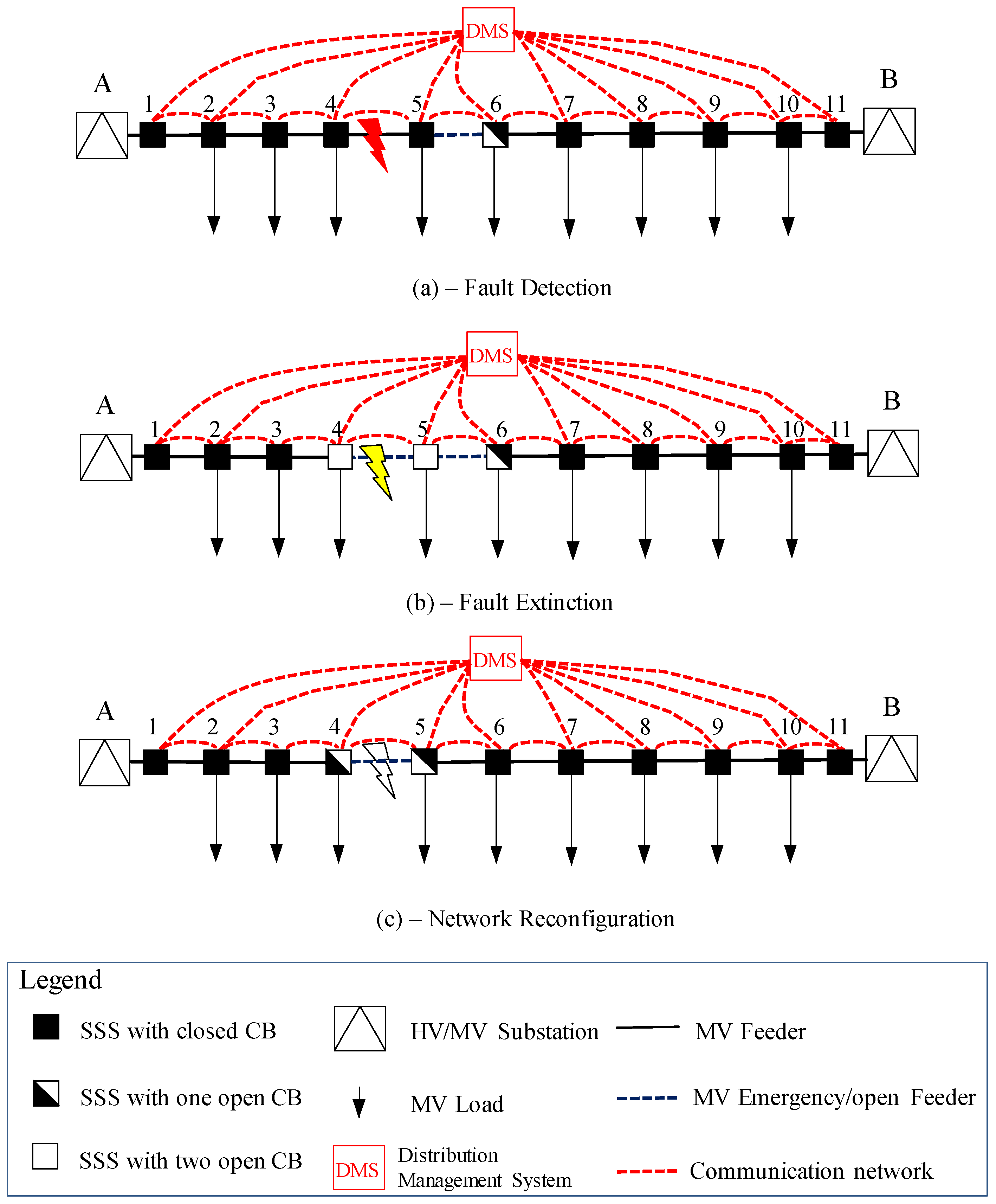
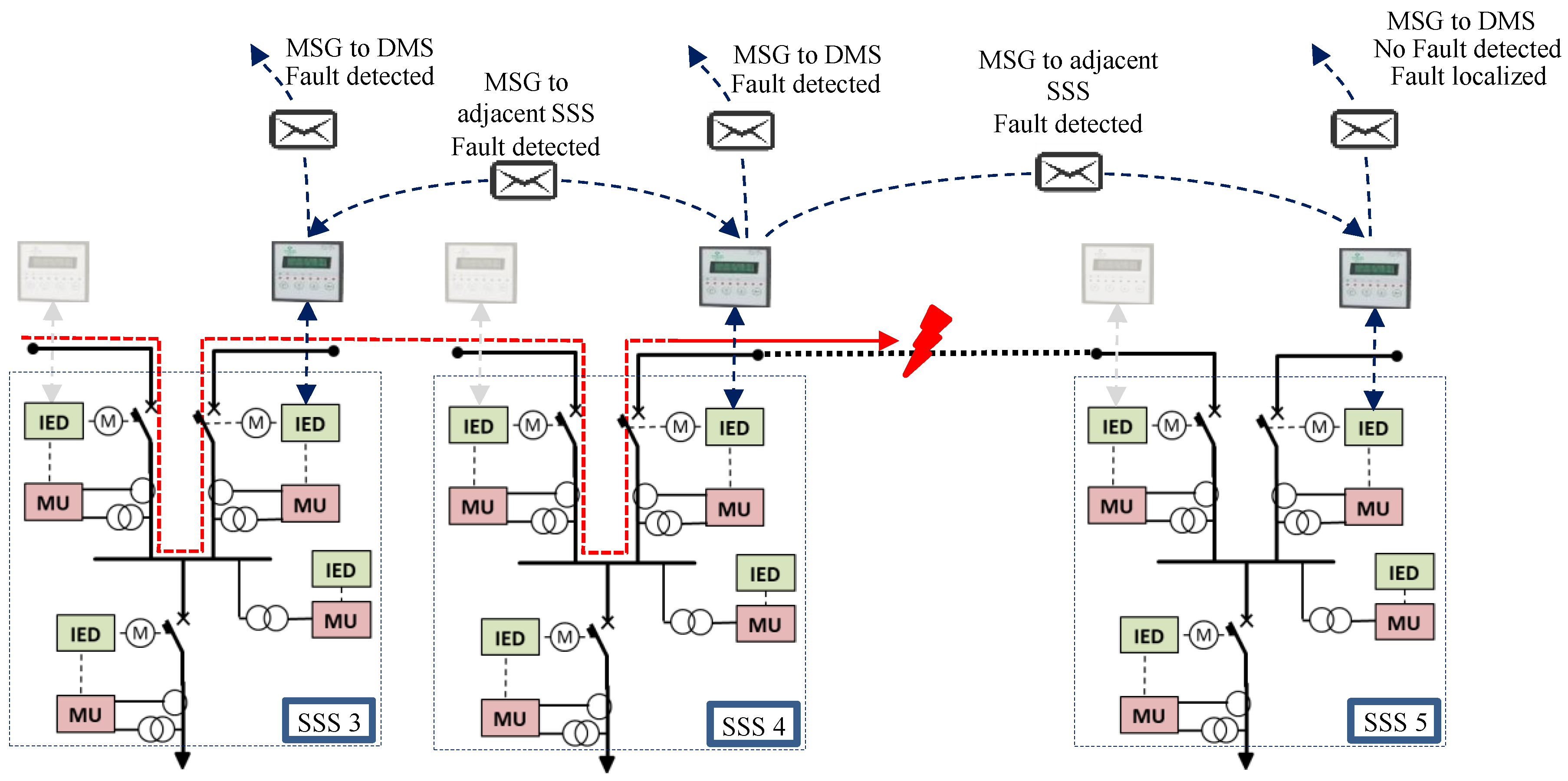
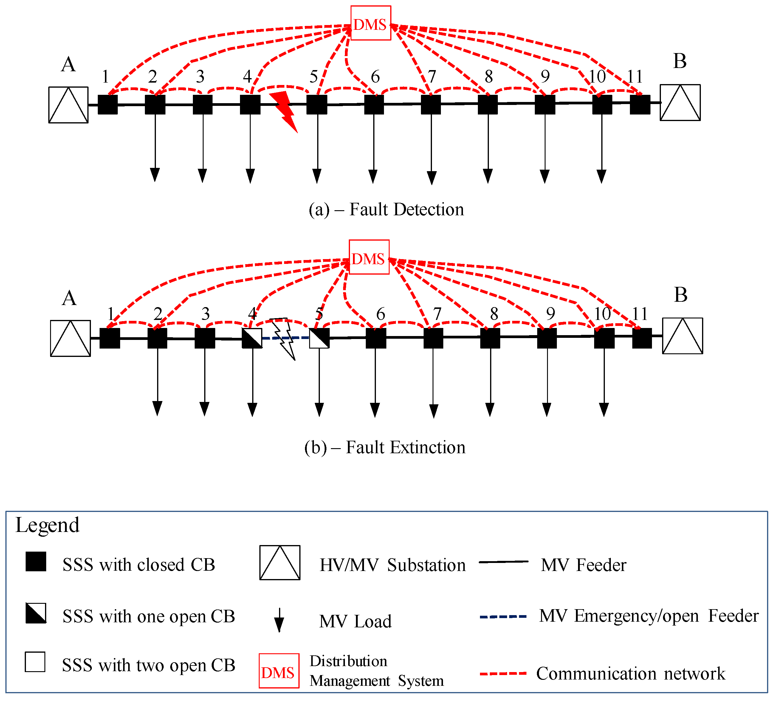
2.2. Fault Detection and Reconfiguration Scheme for Smart Distribution Networks

In distribution systems, network automation and protection systems are designed to minimize the number of power interruptions and to limit outage duration. With smart grid enhancement, the number and outage time of interruptions is expected to be further reduced compared to the current situation.
The operation of circuit breakers is highly time critical since it is necessary to guarantee an instantaneous trigger on breakers to assure an efficient intervention during or after a fault extinction. The implementation of such systems requires a smart grid infrastructure that allows fast location of the fault’s area, interruption of the short circuit current, as well as automation systems to reduce outage duration with automatic reconfiguration. It strongly relies on the performance of the communication system. Compared to wired solutions, such as power line carrier (PLC) or Fiber Optics, this paper investigates the use of wireless technologies for smart grid applications. In fact, they may provide communication abilities with lower cost of equipment and installation, quicker deployment, wide access and flexibility [35].
In this paper, the analyzed communication system was the LTE architecture used in public communication networks. SSS were connected to the communication network through LTE user equipment (UE). A distribution management system (DMS) with supervision/protection/reconfiguration capabilities was also used on the same communication system. Under the proposed protection scheme, each SSS was equipped with two measurement units and IEDs able to detect the direction of the fault currents and communicate with DMS besides the adjacent IEDs. This scheme configured a DMS with decentralized architecture able to provide more flexibility and rapidity of intervention [36,37].
Fault management and the strategy in opening the breakers differs according to the network configuration, meshed or radial. Three-phase short circuit faults are the simplest to be identified and handled. If the network is managed in radial configuration and no distributed generation (DG) exists, the fault is fed only from the primary substation. In this case, the nodes that are located downstream the fault will not detect any fault current. This fault condition is unambiguous and enables fast fault localization. When a reclosing branch is installed in the SSS, the IED is alerted for reconfiguring the network in order to minimize the impact of the fault. In case of meshed networks, the operating characteristic of the directional relays for a three-phase short circuit fault can be depicted as shown in Figure 3. Depending on the phase of the current, it is easy to find the position of the faults analyzing the module and phase of the current.
In this proposed application, a smart selectivity scheme is assumed for three-phase inextinguishable faults. Those faults, even though, are the less frequent and the most critical in distribution networks. In fact, the resonance grounding (neutral grounded with arc suppression coils—Petersen coil), currently used in many European countries, permits choking the fault current below the level of self-extinction (<35–50 A) by compensating the capacitive fault current of the network. By this action, all transient faults can be cleared without feeder tripping.
Considering an example of radial network such as the one represented in Figure 4, in case of three-phase short circuit located between nodes 4 and 5, the fault current will flow from the feeding high voltage (HV) substation A.
In case of fault on branch 4–5 in Figure 3a, the DMS, subsequently to processing information exchanged with the IEDS deployed in SSS, has to:
(1)
locate the fault (branch 4–5);
(2)
open the first circuit breaker upstream the fault (SSS 4) in order to extinguish the fault, providing selectivity (Figure 3b); the load at node 5 is unserved until network reconfiguration is completed.
(3)
Operate the emergency tie (5 and 6, in order to minimize the out of service area. Opening circuit breaker on node 5, on the side of the fault, guarantees that the second HV/MV substation does not feed the fault, and the fault is cleaned (Figure 3c).
(4)
Operate closing of circuit breaker on node 6 permits the reconfiguration of the network and restoring the service to the load at node 5.
In case of fault, when the fault current exceeds the threshold, the IEDs of SSS are activated and send the measured current (module and phase) to the neighboring IEDs positioned in the adjacent SSS (Figure 5) in order to provide a fast localization of the fault.
Each IED that measures the outbound short circuit current will provide a message, e.g., a Generic Object Oriented Substation Event (GOOSE) message using IEC 61850 standard protocol, of the recognized fault to the DMS, and another message to adjacent IEDs. The IED receives a waiting signal from opening the corresponding circuit breaker (CB), the selectivity is obtained and the location of the fault is reached where the IED downstream the fault does not receive any waiting message. After that, the DMS has to communicate with peripheral units sequentially to perform the following actions:
  • opening the CB (e.g., the outbound CB of the SSS4 in Figure 5) at the SSS upstream the fault;
  • opening the CB (e.g., the inbound CB of the SS5 in Figure 5) at the SSS downstream the fault;
  • closing of CB that permits the reconfiguration of the network.
In case of meshed (closed loop) network as the one represented in Figure 6, when a short circuit fault occurs between nodes 4 and 5, the fault current flows from both HV/MV substations A and B.
In this case, each IED that measures the outbound short circuit current from the SSS provides a message of the recognized fault to the DMS, and another message to adjacent IEDs. Itself, it receives a wait signal from opening the corresponding CB, and the location of the fault is reached when two adjacent IEDs register currents with opposed phases. After that, the IEDs send the message to DMS to order the opening of the two CBs (e.g., the outbound CB of the SSS 4 and the inbound CB of SSS 5 in Figure 7) on both sides upstream the fault.

2.3. LTE Communication Technology for Smart Grid Operation

The smart grid concept requires flexible communication architecture that allows power network devices such as sensors, smart meters, IEDs, and protection relays to exchange data in order to achieve an efficient operation of the electrical distribution system. A wide range of communication technologies, both wired and wireless, is nowadays available for building the communication infrastructure supporting smart grid data exchange. Peculiar features characterize each technology, for example data rate, coverage, installation and maintenance costs, reliability, exposure to cyber attacks, etc. Choosing appropriate technology is therefore crucial. Wireless technologies appear as key candidates in building the Smart Grid communications network due to their low installation costs and ease of deployment. Spreading of mobile telecommunication devices has stimulated a committed research over existing communication technologies. GSM, GPRS, EDGE, UMTS are part of a continuous evolution that has led to LTE, which represents one of the fourth-generation mobile technologies (4G). According to International Telecommunication Union (ITU), 4G technologies require to comply certain characteristics, among others [38]:
  • ability to inter-work with other radio technologies;
  • high quality of service;
  • data rate of 100 Mbps in motion and 1 Gbps with fixed installations;
  • sharing of network resources, allowing multiple users per cell;
  • scalable bandwidth from 1.4 to 20 MHz;
  • packet switching IP networks;
  • connection spectral efficiency of 15 bps/Hz in downlink and 6.75 bps/Hz in uplink;
  • operating modes: frequency division duplex (FDD) and time division duplex (TDD).
Currently, LTE is the technology that most efficiently meets all these requirements permitting broad coverage, high throughput, D2D capability, and the more recent LTE-Advanced release (LTE-A) provides the users with performances that are comparable with wired DSL technology [4,5]. Finally, the main features that enable LTE for supporting Smart Grid communication are [4]:
  • Use of licensed bands: Even though the use of licensed bands alone does not grant or prevent cyber attacks, the communication network is robust against cyber attacks and possible stealing of confidential data and permits a better handing of interferences if compared with technologies that operate on license-free bands.
  • Mature and ubiquitous coverage: The communication network span over vast areas, thus permits to integrate even remote endpoints to the main power grid.
  • High performance: High data rate, low latency, and high system reliability enable critical automation tasks within the distribution grid that are often associated with demanding QoS requirements, such as severe time constraints.
  • Third-party operation: It relieves DSOs from having to run and maintain a dedicated communication infrastructure.
For the abovementioned reasons, smart-grid operation considering the 4G LTE communication system, assuming to use the existing public mobile communication system has been chosen.

3. Case Study, Results and Discussion

The objective of this study is to analyze the performances of LTE as a communication carrier for supporting data communication required for FLISR in smart distribution networks, permitting fault location, isolation and service restoration in an acceptable time. In Italy, for example, the regulation of distribution systems includes output-based incentives to DSOs related to the quality of service, and, in particular, short interruptions from 1 s up to 3 min [39] can be subject to penalties or incentives. The DSO then, in order to avoid a worsening of its power quality indices, has to limit the maximum interruption time to under 1 s during faults; for this reason, it needs tools for assessment of communication technologies for smart grids applications like the one presented in this paper.
The proposed FLISR was tested on a real distribution network formed by five feeders, supplied by a HV/MV primary substation, and interconnected with emergency ties that can be used for changing the network reconfiguration. The network under study extended for about 10 km and supplied, through 46 secondary substations, a mix of residential and commercial loads in an urban scenario (Figure 8a). The area was assumed being served by LTE public mobile network, and the distribution of towers/antennas (e.g., eNB nodes in Figure 8b) followed realistic georeferenced data. In Table 1, the major simulation parameters used for the LTE network are reported. A three-phase permanent fault was assumed in branch 8–9, the fault was detected by the protection system of the network and then, the network could be reconfigured for permitting DSO crews to repair the fault.
For the sake of simplicity, but without loss of generality, the simulations shown in the following examples did not consider full implementation of IEC 61850 data model and parameters in IEDs and DMS simulated [28].

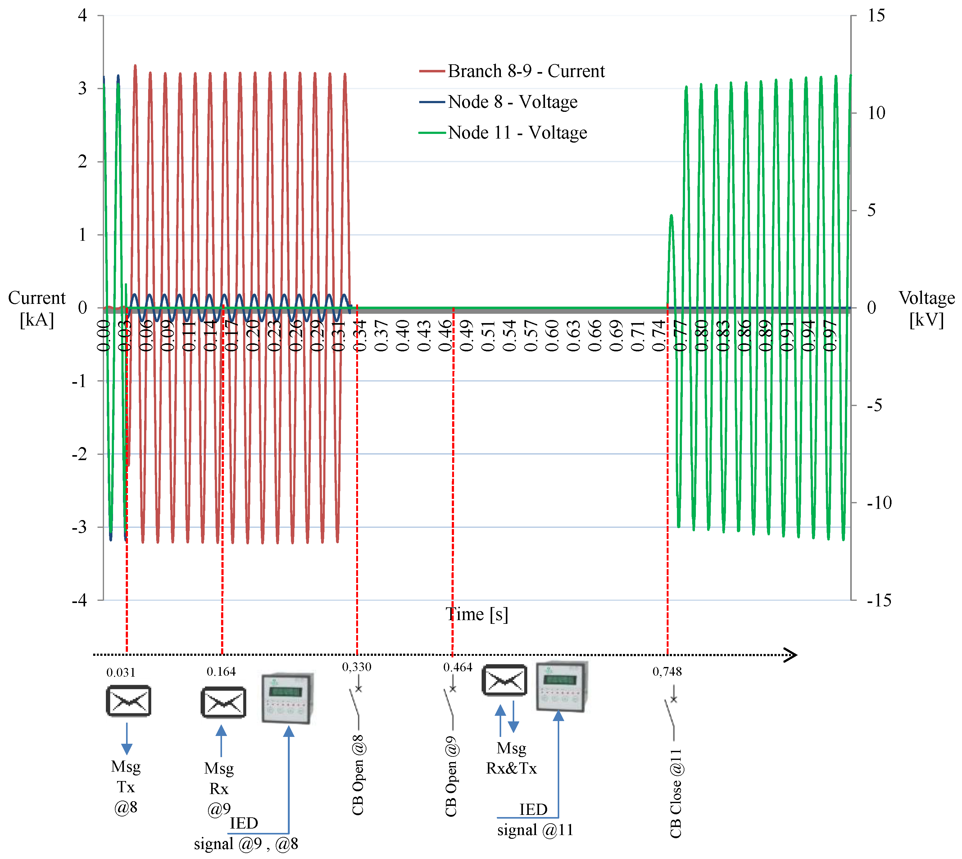
3.1. Radial Network Operation

In the radial operation of the network, the emergency tie between nodes 11 and 33 in Figure 8 was normally open. The co-simulation platform permitted simulating the detection and clearing of the fault condition, as well as the procedure for reconfiguring the network by closing the emergency for minimization of the network area out of service. This case study was of interest, for instance, for DSOs interested to know how much time was necessary to reconfigure the distribution network using LTE communication systems in a smart grid scenario.
The transient caused by a fault is shown in Figure 9. At node 8, after 164 ms from the fault, the IED triggered for opening the breaker, and extinguishing the fault current. The mechanical opening of the breaker was simulated by a time delay, which was randomly extracted from a Gaussian distribution (with mean of 0.2 s and standard deviation of 0.05 s) and the fault was extinguished after 330 ms. A message to the adjacent SSS (node 9) was sent for opening the switch and isolating the faulted network section. The node 11 waited for confirmation of the circuit breaker 9 opening that, due to the mechanical delay in the CB, arrived with a feedback packet at 464 ms. Afterwards, the DMS sent a message to IEDs at nodes 11 and 33 for closing the terminals of the emergency tie. The voltage profile at node 11 showed that the network was reconfigured after 748 ms.

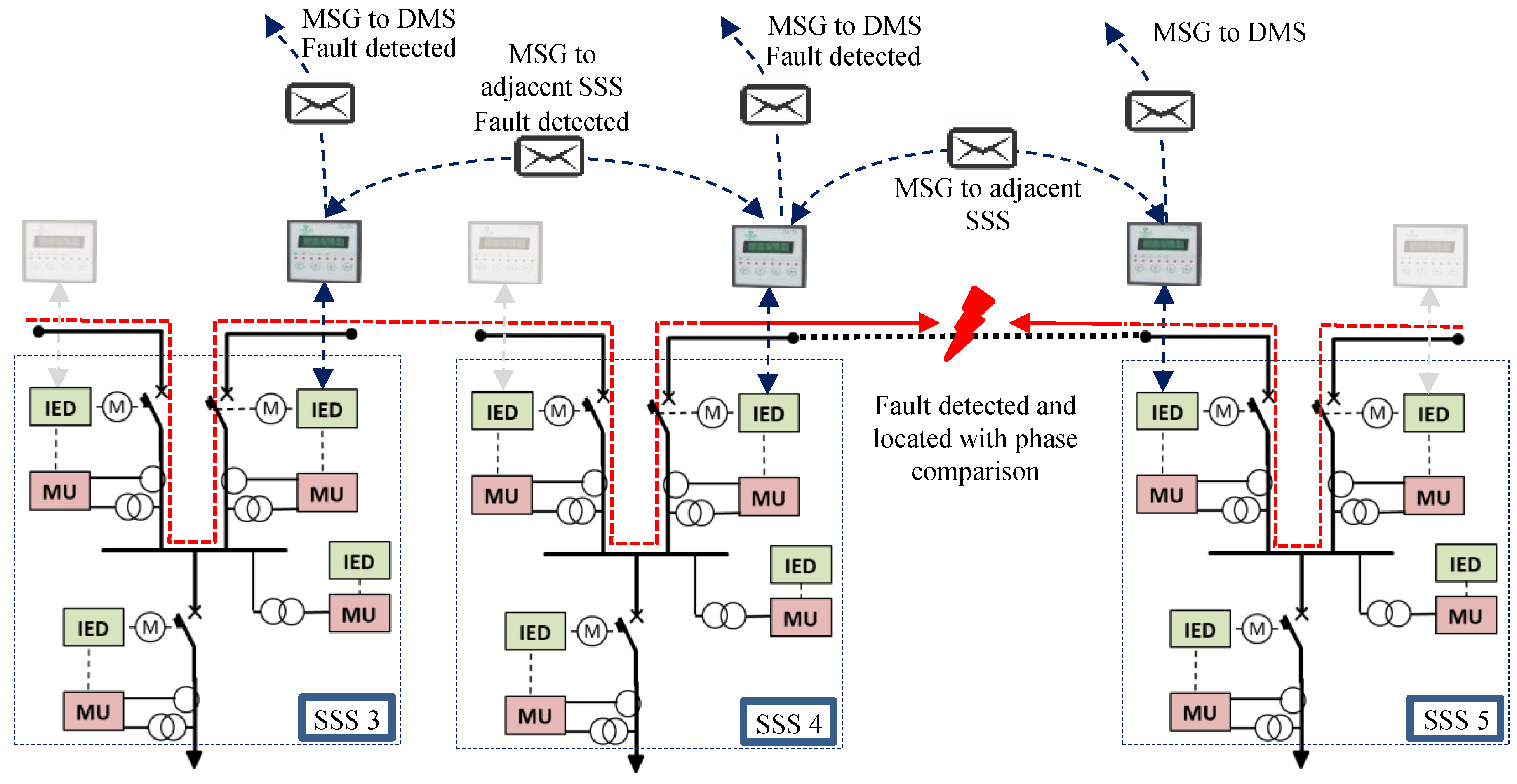
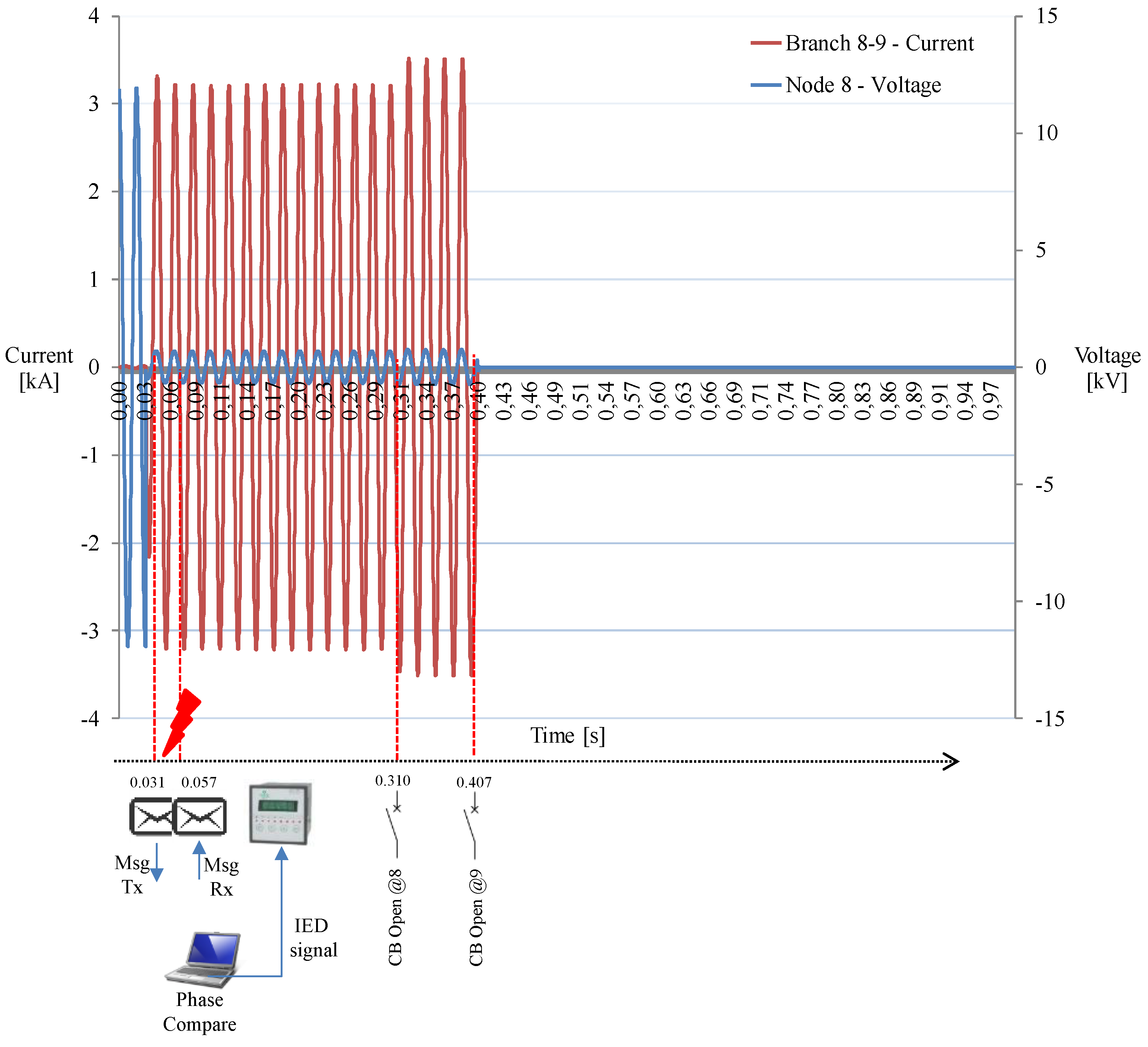
3.2. Meshed Network Operation

The second case analyzed considered a closed loop network operation. This means that the network was operated with switches at substations 8 and 9 normally closed, and the short circuit was fed by two sides.
Figure 10 shows the voltage at node 8, and the current that flowed in the branch between nodes 8 and 9. At 31 ms the overcurrent caused by the short circuit was detected by the IED in the SSS at node 8 that sent a message with current and phase measurement to the neighbors (see Table 2 and Table 3).
At 56 ms, the substation 64 received the message from SSS at node 61, at 57 ms it received the message from SSS in node 67.
The DMS performed a phase comparison between the local measurements received allowing locating the fault. Opening of the two CB was completed in 377 ms. The communication took 27 ms, and 350 ms of mechanical delay was also considered. The network was reconfigured after 407 ms.

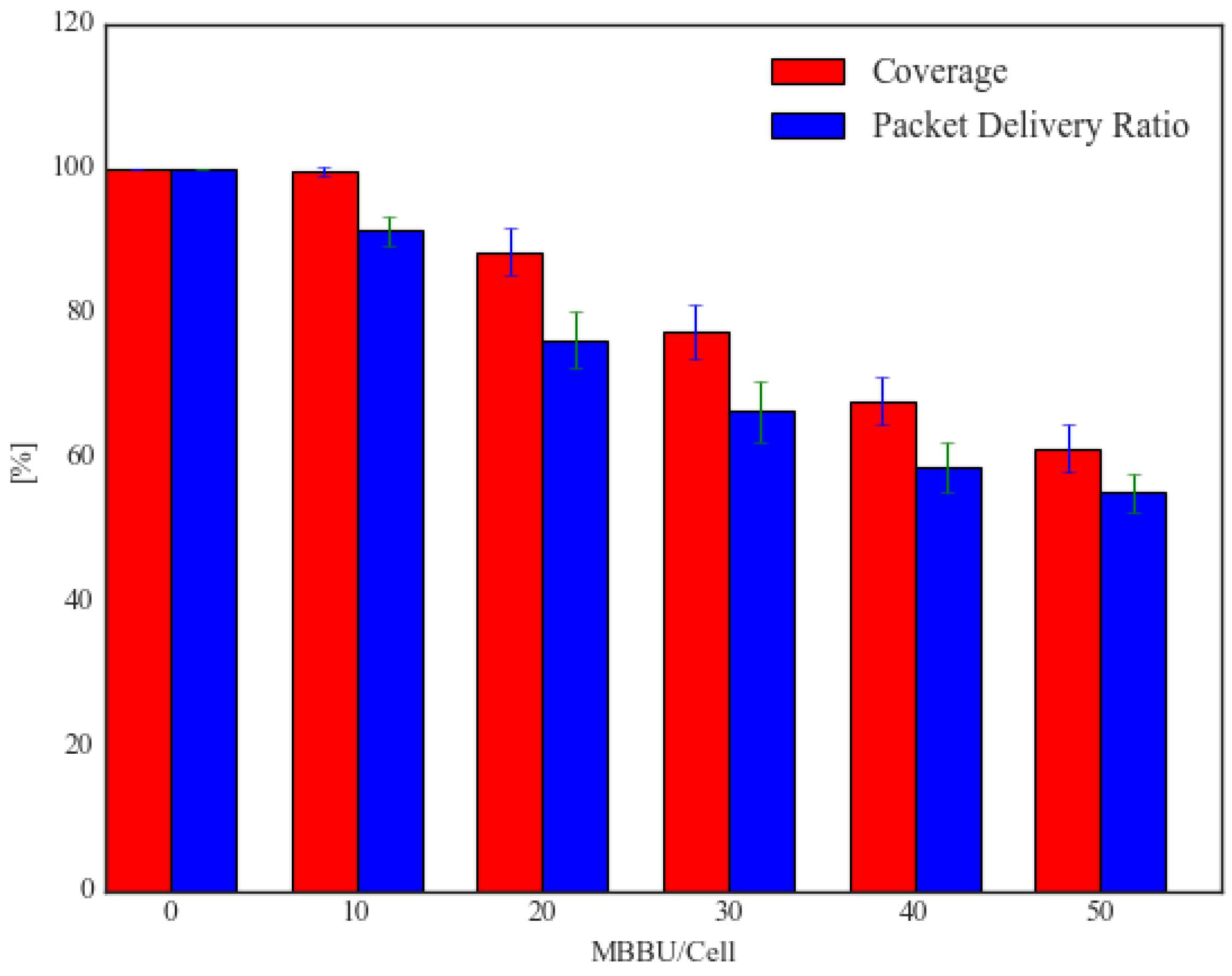
3.3. Backgroud Traffic Analysis

The simulations were executed in a more realistic situation considering the same network but different background conditions, in order to verify the LTE performances when a number of user are contemporarily connected to the same communication network. The first case considered a variable number of generic Mobile Broadband Users that were contemporarily active in the LTE network (MBBU). Several cases were considered with 0 (ideal case), to 50 MBBU per cell. Figure 11 shows the performances in terms of packet delivery ratios and coverage with variable active users per cell for typical LTE usage in a dense urban scenario with optimal exploitation of LTE network [40]. Overcharging the LTE network caused reduction in coverage that decreases to 90%, and a slight increase of the transmission delay of the packets. The coverage further decreased with more than 30 users per cell, what showed the congestion of the network and poor performances of the User Datagram Protocol (UDP) protocol in terms of packet loss. It has to be underlined that the low latency and packet drop could be obtained with an efficient planning of communication system cells [41].
Finally, in Figure 12, the performances variation of LTE in terms of delay and throughput are reported with a variable number of background traffic due to contemporary served MBBU. The delay increased on average from 28 ms up to 45 ms (with a maximum value observed during the repetitions of the scenario of 67 ms) in the scenario with 10 MBBU per cell. In the scenarios with more than 20 MBBU per cell the delay did not grow and was asymptotically held below 45 ms. This behavior was due to the congestion of LTE network over 20 MBBU per cell, that caused the rejection of new connections keeping the delays approximately unvaried. The saturation of the throughput for 20 up to 50 MBBU per cell demonstrated that the volume of data exchanged with the LTE network did not increase when charging the network over the number of 10 MBBU per cell.

4. Conclusions

The implementation of an automatic fast reconfiguration scheme of the electric distribution network strongly relies on the performance of the communication system. Compared to wired dedicated solutions, such as PLC or Fiber Optics, public wireless technologies offer an easier implementation of a communication link among IEDs at lower costs, but the doubt on their performance degradation due to the sharing with other users retards their exploitation. In this paper, the LTE communication technology has been tested with different traffic background conditions on a realistic case study using a co-simulation tool. According to the first results presented in this paper, LTE was technically able to start the intervention of protection devices in less than 100 ms, and showed to be adequate for FLISR applications related to Smart Grid implementation.

Author Contributions

F.P., G.C., E.G., and S.C. conceived the idea behind this research, designed the simulations and wrote the paper; M.G. developed the software, performed the simulations and wrote some parts of the manuscript; all the authors analyzed the data and proofread the paper.

Funding

This work has been partly financed by the Research Fund for the Italian Electrical System under the Contract Agreement between RSE S.p.A. and the Ministry of Economic Development—General Directorate for Nuclear Energy, Renewable Energy and Energy Efficiency in compliance with the Decree of 8 March 2006.

Conflicts of Interest

The authors declare no conflict of interest.

References

  1. D’adamo, C.; Abbey, C.; Jupe, S.; Buchholz, B.; Khattabi, M.; Pilo, F. Development and operation of active distribution networks: Results of CIGRE C6.11 working group. In Proceedings of the 21st International Conference on Electricity Distribution, Frankfurt, Germany, 6–9 June 2011; Volume 6. [Google Scholar]
  2. Control and Automation Systems for Electricity Distribution Networks (EDN) of the Future. Available online: https://e-cigre.org/publication/711-control-and-automation-systems-for-electricity-distribution-networks-edn-of-the-future (accessed on 17 April 2018).
  3. Garau, M.; Celli, G.; Ghiani, E.; Soma, G.G.; Pilo, F.; Corti, S. ICT reliability modelling in co-simulation of smart distribution networks. In Proceedings of the 2015 IEEE 1st International Forum on Research and Technologies for Society and Industry Leveraging a Better Tomorrow (RTSI), Turin, Italy, 6–18 September 2015; pp. 365–370. [Google Scholar] [CrossRef]
  4. Kalalas, C.; Thrybom, L.; Alonso-Zarate, J. Cellular Communications for Smart Grid Neighborhood Area Networks: A Survey. IEEE Access 2016, 4, 1469–1493. [Google Scholar] [CrossRef]
  5. Garau, M.; Celli, G.; Ghiani, E.; Pilo, F.; Corti, S. Evaluation of Smart Grid Communication Technologies with a Co-Simulation Platform. IEEE Wirel. Commun. 2017, 24, 42–49. [Google Scholar] [CrossRef]
  6. Patel, A.; Aparicio, J.; Tas, N.; Loiacono, M.; Rosca, J. Assessing communications technology options for smart grid applications. In Proceedings of the 2011 IEEE International Conference on Smart Grid Communications (SmartGridComm), Brussels, Belgium, 17–20 October 2011; pp. 126–131. [Google Scholar] [CrossRef]
  7. Brown, J.; Khan, J.Y. Key performance aspects of an LTE FDD based Smart Grid communications network. Comput. Commun. 2013, 36, 551–561. [Google Scholar] [CrossRef]
  8. Markkula, J.; Haapola, J. Impact of smart grid traffic peak loads on shared LTE network performance. In Proceedings of the 2013 IEEE International Conference on Communications (ICC), Budapest, Hungary, 9–13 June 2013; pp. 4046–4051. [Google Scholar] [CrossRef]
  9. Cheng, P.; Wang, L.; Zhen, B.; Wang, S. Feasibility study of applying LTE to Smart Grid. In Proceedings of the 2011 IEEE First International Workshop on Smart Grid Modeling and Simulation (SGMS), Brussels, Belgium, 17 October 2011; pp. 108–113. [Google Scholar] [CrossRef]
  10. Andrén, F.P.; Strasser, T.I.; Kastner, W. Engineering Smart Grids: Applying Model-Driven Development from Use Case Design to Deployment. Energies 2017, 10, 374. [Google Scholar] [CrossRef]
  11. Stifter, M.; Kazmi, J.H.; Andrén, F.; Strasser, T. Co-simulation of power systems, communication and controls. In Proceedings of the 2014 Workshop on Modeling and Simulation of Cyber-Physical Energy Systems (MSCPES), Berlin, Germany, 14 April 2014; pp. 1–6. [Google Scholar] [CrossRef]
  12. Li, W.; Ferdowsi, M.; Stevic, M.; Monti, A.; Ponci, F. Cosimulation for Smart Grid Communications. IEEE Trans. Ind. Inform. 2014, 10, 2374–2384. [Google Scholar] [CrossRef]
  13. Hopkinson, K.; Wang, X.; Giovanini, R.; Thorp, J.; Birman, K.; Coury, D. EPOCHS: A platform for agent-based electric power and communication simulation built from commercial off-the-shelf components. IEEE Trans. Power Syst. 2006, 21, 548–558. [Google Scholar] [CrossRef]
  14. Lin, H.; Veda, S.S.; Shukla, S.S.; Mili, L.; Thorp, J. GECO: Global Event-Driven Co-Simulation Framework for Interconnected Power System and Communication Network. IEEE Trans. Smart Grid 2012, 3, 1444–1456. [Google Scholar] [CrossRef]
  15. Mets, K.; Verschueren, T.; Develder, C.; Vandoorn, T.L.; Vandevelde, L. Integrated simulation of power and communication networks for smart grid applications. In Proceedings of the 2011 IEEE 16th International Workshop on Computer Aided Modeling and Design of Communication Links and Networks (CAMAD), Kyoto, Japan, 10–11 June 2011; pp. 61–65. [Google Scholar] [CrossRef]
  16. Cintuglu, M.H.; Ma, T.; Mohammed, O. Protection of Autonomous Microgrids using Agent-Based Distributed Communication. IEEE Trans. Power Deliv. 2016, 32, 351–360. [Google Scholar] [CrossRef]
  17. Mueller, S.C.; Georg, H.; Nutaro, J.J.; Widl, E.; Deng, Y.; Palensky, P.; Awais, M.U.; Chenine, M.; Kuch, M.; Stifter, M.; et al. Interfacing Power System and ICT Simulators: Challenges, State-of-the-Art, and Case Studies. IEEE Trans. Smart Grid 2016, 9, 14–24. [Google Scholar] [CrossRef]
  18. Palensky, P.; van der Meer, A.A.; Lopez, C.D.; Joseph, A.; Pan, K. Applied Cosimulation of intelligent power systems: Implementation, usage, and examples. IEEE Ind. Electron. Mag. 2017, 11, 6–21. [Google Scholar] [CrossRef]
  19. Kazmi, J.H.; Latif, A.; Ahmad, I.; Palensky, P.; Gawlik, W. A flexible smart grid co-simulation environment for cyber-physical interdependence analysis. In Proceedings of the 2016 Workshop on Modeling and Simulation of Cyber-Physical Energy Systems (MSCPES), Vienna, Austria, 11 April 2016; pp. 1–6. [Google Scholar] [CrossRef]
  20. Bottura, R.; Babazadeh, D.; Zhu, K.; Borghetti, A.; Nordström, L.; Nucci, C.A. SITL and HLA Co-simulation Platforms: Tools forAnalysis of the Integrated ICT and Electric Power System. In Proceedings of the 2013 IEEE EUROCON, Zagreb, Croatia, 1–4 July 2013. [Google Scholar]
  21. Ahmad, I.; Kazmi, J.H.; Shahzad, M.; Palensky, P.; Gawlik, W. Co-simulation framework based on power system, AI and communication tools for evaluating smart grid applications. In Proceedings of the 2015 IEEE Innovative Smart Grid Technologies—Asia (ISGT ASIA), Bangkok, Thailand, 3–6 November 2015; pp. 1–6. [Google Scholar] [CrossRef]
  22. Moulema, P.; Yu, W.; Griffith, D.; Golmie, N. On Effectiveness of Smart Grid Applications Using Co-Simulation. In Proceedings of the 2015 24th International Conference on Computer Communication and Networks (ICCCN), Las Vegas, NV, USA, 3–6 August 2015; pp. 1–8. [Google Scholar] [CrossRef]
  23. Sadi, M.A.H.; Ali, M.H.; Dasgupta, D.; Abercrombie, R.K.; Kher, S. Co-Simulation Platform for Characterizing Cyber Attacks in Cyber Physical Systems. In Proceedings of the 2015 IEEE Symposium Series on Computational Intelligence, Cape Town, South Africa, 7–10 December 2015; pp. 1244–1251. [Google Scholar] [CrossRef]
  24. Sadi, M.A.H.; Ali, M.H.; Dasgupta, D.; Abercrombie, R.K. OPNET/Simulink Based Testbed for Disturbance Detection in the Smart Grid. In Proceedings of the 10th Annual Cyber and Information Security Research Conference, CISR ’15, Oak Ridge, TN, USA, 7–9 April 2015; ACM: New York, NY, USA, 2015; pp. 17:1–17:4. [Google Scholar] [CrossRef]
  25. Dong, X.; Lin, H.; Tan, R.; Iyer, R.K.; Kalbarczyk, Z. Software-Defined Networking for Smart Grid Resilience: Opportunities and Challenges. In Proceedings of the 1st ACM Workshop on Cyber-Physical System Security, Denver, CO, USA, 12–16 October 2015; ACM: New York, NY, USA, 2015; pp. 61–68. [Google Scholar] [CrossRef]
  26. Venkataramanan, V.; Srivastava, A.; Hahn, A. Real-time co-simulation testbed for microgrid cyber-physical analysis. In Proceedings of the 2016 Workshop on Modeling and Simulation of Cyber-Physical Energy Systems (MSCPES), Vienna, Austria, 11 April 2016; pp. 1–6. [Google Scholar] [CrossRef]
  27. Virdis, A.; Stea, G.; Nardini, G. Simulating LTE/LTE-Advanced Networks with SimuLTE. In Simulation and Modeling Methodologies, Technologies and Applications; Springer: Cham, Switzerland, 2015; pp. 83–105. [Google Scholar]
  28. Alvarez de Sotomayor, A.; Della Giustina, D.; Massa, G.; Dedè, A.; Ramos, F.; Barbato, A. IEC 61850-based adaptive protection system for the MV distribution smart grid. Sustain. Energy Grids Netw. 2017. [Google Scholar] [CrossRef]
  29. Dedè, A.; Giustina, D.D.; Massa, G.; Cremaschini, L. Toward a New Standard for Secondary Substations: The Viewpoint of a Distribution Utility. IEEE Trans. Power Deliv. 2017, 32, 1123–1132. [Google Scholar] [CrossRef]
  30. Coppo, M.; Pelacchi, P.; Pilo, F.; Pisano, G.; Soma, G.G.; Turri, R. The Italian smart grid pilot projects: Selection and assessment of the test beds for the regulation of smart electricity distribution. Electr. Power Syst. Res. 2015, 120, 136–149. [Google Scholar] [CrossRef]
  31. Botton, S.; Cavalletto, L.; Marmeggi, F. Schema project-innovative criteria for management and operation of a closed ring MV network. In Proceedings of the 22nd International Conference and Exhibition on Electricity Distribution (CIRED 2013), Stockholm, Sweden, 10–13 June 2013; pp. 1–4. [Google Scholar] [CrossRef]
  32. Wolter, D.; Zdrallek, M.; Stötzel, M.; Schacherer, C.; Mladenovic, I.; Biller, M. Impact of meshed grid topologies on distribution grid planning and operation. CIRED-Open Access Proc. J. 2017, 2017, 2338–2341. [Google Scholar] [CrossRef]
  33. Hadjsaid, N.; Alvarez-Hérault, M.C.; Caire, R.; Raison, B.; Descloux, J.; Bienia, W. Novel architectures and operation modes of distribution network to increase DG integration. In Proceedings of the IEEE PES General Meeting, Providence, RI, USA, 25–29 July 2010; pp. 1–6. [Google Scholar] [CrossRef]
  34. Celli, G.; Pilo, F.; Pisano, G.; Allegranza, V.; Cicoria, R.; Iaria, A. Meshed vs. radial MV distribution network in presence of large amount of DG. In Proceedings of the IEEE PES Power Systems Conference and Exposition, New York, NY, USA, 10–13 October 2004; Volume 2, pp. 709–714. [Google Scholar] [CrossRef]
  35. Jiang, J.; Qian, Y. Distributed Communication Architecture for Smart Grid Applications. IEEE Commun. Mag. 2016, 54, 60–67. [Google Scholar] [CrossRef]
  36. Matos, M.A.; Seca, L.; Madureira, A.G.; Soares, F.J.; Bessa, R.J.; Pereira, J.; Peças Lopes, J. Control and Management Architectures. In Smart Grid Handbook; John Wiley & Sons, Ltd.: Hoboken, NJ, USA, 2016; ISBN 978-1-118-75547-1. [Google Scholar]
  37. D’adamo, C.; Valtorta, G.; Consiglio, L.; Cerretti, A.; D’orazio, L.; Malerba, A.; Marmeggi, F. Smart fault selection: New operational criteria and challenges for the large-scale deployment in e-distribuzione’s network. CIRED-Open Access Proc. J. 2017, 2017, 1475–1478. [Google Scholar] [CrossRef]
  38. Korowajczuk, L. LTE, WiMAX and WLAN Network Design, Optimization and Performance Analysis, 1st ed.; Korowajczuk, L., Ed.; Wiley: Chichester, UK, 2011; ISBN 978-0-470-74149-8. [Google Scholar]
  39. Aeegsi, A. per l’Energia E., il Gas ed il Sistema Idrico. Testo Integrato Della Regolazione Della Qualità Dei Servizi di Distribuzione e Misura Dell’energia Elettrica. 2014. Available online: https://www.autorita.energia.it/allegati/docs/11/198-11argtiqe_new.pdf (accessed on 18 May 2018).
  40. Auer, G.; Giannini, V.; Desset, C.; Godor, I.; Skillermark, P.; Olsson, M.; Imran, M.A.; Sabella, D.; Gonzalez, M.J.; Blume, O.; et al. How much energy is needed to run a wireless network? IEEE Wirel. Commun. 2011, 18, 40–49. [Google Scholar] [CrossRef]
  41. Saxena, N.; Roy, A.; Kim, H. Efficient 5G Small Cell Planning With eMBMS for Optimal Demand Response in Smart Grids. IEEE Trans. Ind. Inform. 2017, 13, 1471–1481. [Google Scholar] [CrossRef]
Figure 1. Schematic representation of the co-simulation tool proposed.
Energies 11 01332 g001
Figure 2. Schematic representation of (a) conventional secondary substation, (b) smart secondary substation.
Energies 11 01332 g002
Figure 3. Operating characteristic of the directional criteria for three-phase short circuit faults.
Energies 11 01332 g003
Figure 4. Radial distribution network reconfiguration managed with emergency tie.
Energies 11 01332 g004
Figure 5. Short circuit current direction during three-phase fault in radial network.
Energies 11 01332 g005
Figure 6. Fault detection and extinction in meshed distribution network.
Energies 11 01332 g006
Figure 7. Short circuit current direction during three phase fault with meshed network.
Energies 11 01332 g007
Figure 8. Case study: (a) Distribution network, (b) superimposed mobile LTE communication network.
Energies 11 01332 g008
Figure 9. Voltage/current profiles: Voltage profile at node 8, and current profile in branch 8–9.
Energies 11 01332 g009
Figure 10. Voltage profile at node 8, and current profile in branch 8–9.
Energies 11 01332 g010
Figure 11. Coverage and packet delivery ratio in background traffic scenario.
Energies 11 01332 g011
Figure 12. Communication delay and throughput in background traffic scenario.
Energies 11 01332 g012
Table 1. LTE communication network parameters.
LTE Related ParameterValue
3GPP standard versionRelease 10
Channel model (ITU scenario)Urban Macrocell
Carrier Frequency1800 MHz
Channel Bandwidth20 MHz
Antenna Gain e-NodeB18 dBm
Thermal Noise−101 dBm
UE Noise Figure2 dBm
e-NodeB Noise Figure5 dBm
Packet Size216 B
ProtocolUDP
Table 2. Node 8 current module/phase measurements.
Current [kA]Phase [rad]
Infeed1.7722.920 (cosϕ = −0.976)
Outfeed−1.7860.220 (cosϕ = 0.976)
Table 3. Node 9 received current module/phase measurements.
Time Rx [ms]Current [kA]Phase [rad]
Preceding SSS (node 8)56−1.0570.077 (cosϕ = 0.997)
Following SSS (node 10)57−1.4330.259 (cosϕ = 0.967)

