Article

Modeling and Control of a Combined Heat and Power Unit with Two-Stage Bypass

1
School of Control and Computer Engineering, North China Electric Power University, Beijing 102206, China
2
Beijing Guodian Zhishen Control Technology CO., Ltd., Beijing 102200, China
*
Author to whom correspondence should be addressed.
Energies 2018, 11(6), 1395; https://doi.org/10.3390/en11061395
Submission received: 10 May 2018 / Revised: 24 May 2018 / Accepted: 25 May 2018 / Published: 30 May 2018
(This article belongs to the Special Issue Control and Nonlinear Dynamics on Energy Conversion Systems)

Abstract

:
This paper presents a non-linear dynamic model of a combined heat and power (CHP) unit with two-stage bypass for the first time. This model is derived through an analysis of the material and energy balance of the CHP unit. The static parameters are determined via the design data of the CHP unit, and the dynamic parameters refer to model parameters of same type of units in other references. Based on the model, an optimized control scheme for the coordination system of the unit is proposed. This scheme introduces a stair-like feedforward-feedback predictive control algorithm to solve the control problem of large delays in boiler combustion, and integrates decoupling control to reduce the effect of external disturbance on the main steam pressure. Simulation results indicate that the model effectively reflects the dynamics of the CHP unit and can be used for designing and verifying its coordinated control system; the control scheme can achieve decoupling control of the CHP unit; the fluctuation of main steam pressure is considerably reduced; and the adjustment of coal feed flow is stable. In this case, the proposed scheme can guarantee the safe, stable and flexible operation of the unit and lay the foundation for decoupling the heat load-based constraint of CHP units, thereby expanding the access space of wind power in northern China.

Graphical Abstract

1. Introduction

In recent years, the installed capacity of wind turbines in China has increased at an alarming rate [1,2]; however, the phenomenon whereby wind power is abandoned is very serious, especially in northern China. This condition is attributed to the particularly scarce peak-load regulation power (hydropower and condensing unit) in these areas compared with the numerous combined heat and power (CHP) units. The CHP units have considerable environmental and financial benefits when compared to conventional energy generation [3,4,5,6,7]. However, a CHP unit is subject to a heat load-based constraint, which causes its power output to be high in the heating season and limits the access space of wind power in the grid [8]. On the basis of this issue, the North-East Energy Regulatory Bureau promulgated the “Special Reform Program for the North-East Electric Power Auxiliary Service Market [9]” and the “North-East Electric Power Auxiliary Service Market Operation Rules (Trial) [10]” in November 2016. The policy aims to give full play to the economic leverage, optimize peaking resources through marketization, and allow operators to maximize their effectiveness. The main idea of this policy is to compensate thermal power units with high peaking rates. The compensation funds are shared equally by wind power, nuclear power, and thermal power units with low peak peaking rates. In order to significantly reduce the phenomenon of the abandonment of wind power and increase its access space in the grid, the National Energy Administration officially launched pilot projects to improve the flexibility of thermal power units in 2016 [11]. After comprehensive comparison and selection, 22 thermal power plants in areas with prominent problems of renewable energy consumption were selected as pilot projects. It can be seen that the flexible operation of thermal power units meets the major needs of the national energy industry and is supported by the policies of the National Energy Administration. For the special situation in northern China, wind power would have significant access space to the power grid if the heat load-based constraints are decoupled during the heating season. In this case, decoupling the heat load-based constraints of CHP units is an important means to solve the problem of wind power consumption in northern China.
Currently, the main methods for decoupling the heat load-based constraint of CHP units are bypass heating, electric heating, and heat storage methods [12]. In bypass heating, part of the main steam is cooled and decompressed directly to heat circulating water in the heat supply network. This method does not meet the designed operating conditions of CHP units. However, all related equipment has a certain degree of anti-fatigue capacity at a design time, and a small deviation from design conditions has a slight effect on equipment wear and service life. In electric heating [13], part of the electricity produced by a CHP unit is directly used to heat the circulating water in the heat supply network. This method is equivalent to using excess wind power rather than CHP units for heating from the point of view of power grid. Thus, significant coal-saving benefits are gained. However, the renovation costs of electric heating equipment (electric boiler) are extremely high. In heat storage heating [14,15,16,17], the storage tank begins to store heat when the heating capacity of the CHP unit is sufficient and then releases heat when the heating capacity of the CHP unit is insufficient. The coal-saving benefits are obvious, considering that no conversion of high-quality energy to low-quality energy occurs. The work presented in this paper focuses on the first aforementioned method, bypass heating, and mainly focuses on its effect on the energy balance of a CHP unit. Such a study provides a solid foundation for the safe operation of the CHP unit with two-stage bypass.
Recently, research of the bypass system has mainly focused on the process of start-up, shut-down, and rapid load changes. In order to study the dynamics of bypass temperature, Zhou, Y et al. established a dynamic model for a high-pressure bypass system, verified by fast cut back (FCB) field test data. The results show that the model has high degree of accuracy. Moreover, an improved control technology is proposed to solve the bypass over-temperature problem during FCB. Simulation results show that the improved control technology is better than the traditional controller. However, this model is only a partial model of the bypass system and cannot demonstrate the effect of the bypass on the energy balance of the unit. Therefore, this model cannot be used to design and verify the coordinated control system (CCS) of the unit [18]. Considering that people are increasingly interested in the optimization of bypass controllers and actuators, Pugi et al. presented a model for real-time simulation of a steam plant, and on this basis, they developed a modular Simulink library of components such as heaters, turbines, and valves. This model has been used for closed-loop testing of hardware such as bypass controllers and valve positioners [19]. Considering the dynamics of the bypass system, the feedwater system and the feedwater heater during FCB, Wang et al. established a dynamic model for a coal-fired unit. The effectiveness of the model was verified by FCB field tests [20]. Although there are many studies on the bypass system, the research content only focuses on special working conditions of the unit and has not considered bypass heating. In order to fundamentally analyze the effect of the bypass heating on the energy balance of CHP units, it is necessary to further study the dynamics of CHP units. In recent years, researchers have conducted extensive studies on the drum-boiler model of CHP units. On the basis of the dynamic model of a drum-boiler condensing unit [21,22,23], Liu et al. established a three input, three output, and nonlinear dynamic model for a drum-boiler CHP unit. The inputs of the model are coal feed flow, valve position of turbine, and valve position for heating. The outputs of the model are the main steam pressure, electrical load, and heating steam flow. The simulation results indicate that the control methods of CHP and condensing units are basically the same and there is a more flexible way to improve the load ramp rate of CHP units (valve throttling for heating). However, heating steam pressure is generally used as the controlled variable for heat load rather than heating steam flow [24]. Considering that the problem exists in [24], Liu et al. presented a mathematical model for a drum-boiler CHP unit, a model that differs from that described in [24] in which heating steam pressure is used as the controlled variable for heat load. The simulation results indicate that the model effectively reflects the dynamics of a CHP unit. However, the effect of bypass heating method on the CHP unit is not considered [25]. To deeply analyze the effect of bypass heating on the energy balance of a CHP unit and ensure the safe operation of the unit, a dynamic model of a CHP unit with two-stage bypass should be established.
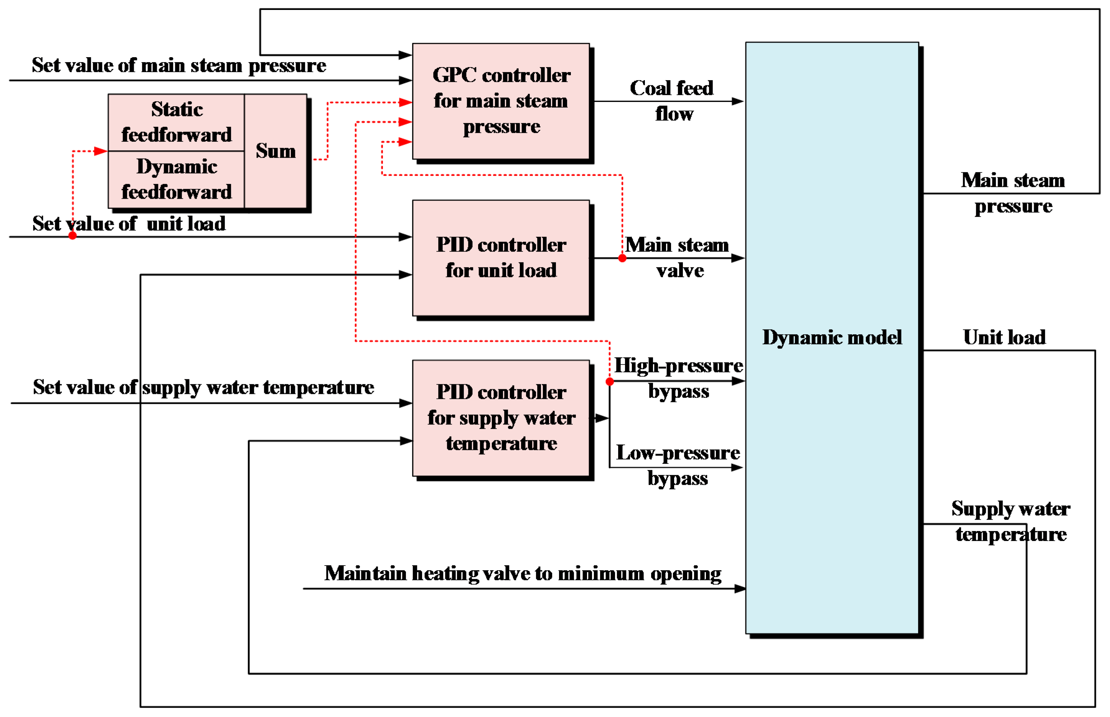
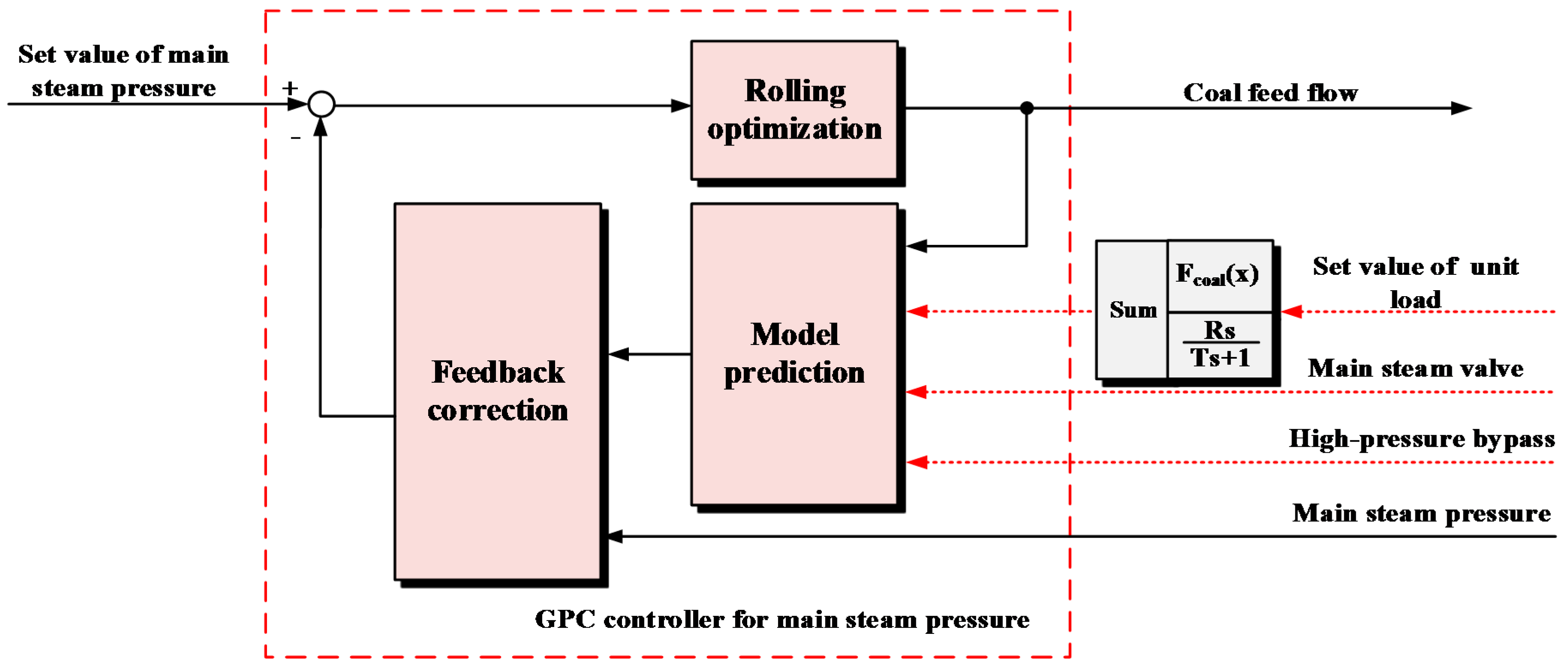
On the basis of [24,25], a five input, three output, and nonlinear dynamic model of a CHP unit with two-stage bypass is proposed in the current study. The effect of bypass heating on the energy balance of the CHP unit is considered. Based on the model, an optimized control scheme for the CCS of the unit is proposed. In this scheme, a stair-like feedforward-feedback predictive control algorithm is taken as key to solving the control problem of large delays in boiler combustion, and the decoupling control is integrated into the scheme to reduce the effect of external disturbance on main steam pressure. Simulation results indicate that the model effectively reflects the dynamics of the CHP unit and can be used for designing and verifying its coordinated control system. The control scheme can achieve decoupling control of the CHP unit, the fluctuation of main steam pressure is considerably reduced, and the adjustment of coal feed flow is stable. In this case, the proposed scheme can guarantee the safe, stable, and flexible operation of the CHP unit and lay the foundation for decoupling the heat load-based constraint of CHP units, thereby expanding the access space of wind power in northern China.
This paper is organized as follows. Section 2 presents a brief introduction of the bypass heating method. Section 3 deduces and establishes a nonlinear dynamic model for a CHP unit with two-stage bypass and contains a simple verification of the model dynamics. Section 4 designs an optimized control scheme for the unit. Section 5 simulates and verifies the control scheme proposed in the former section. Section 6 presents the conclusion of this paper.

2. Working Principle of the Bypass Heating Method

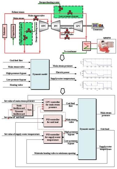
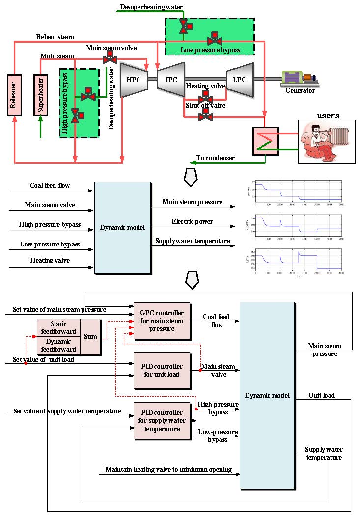
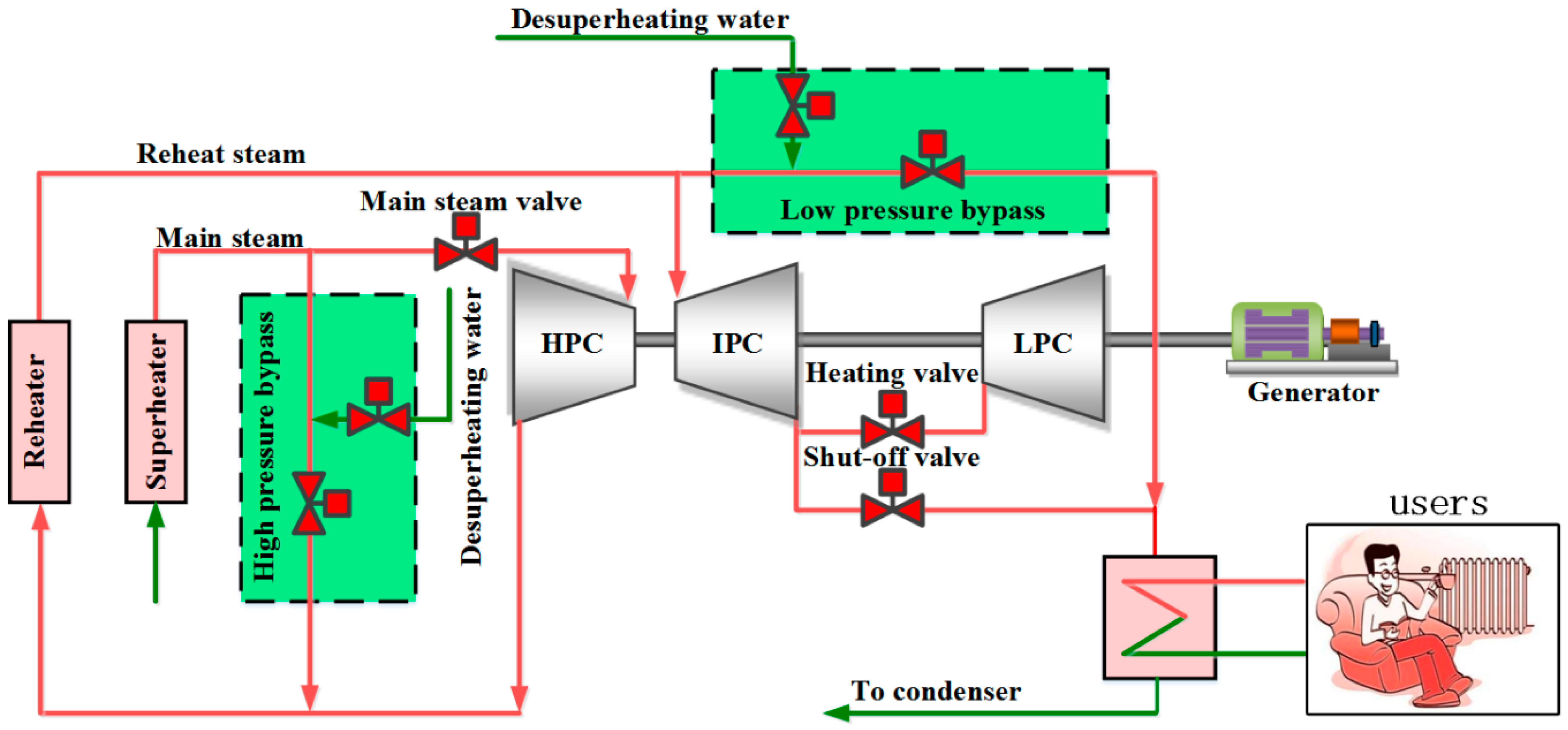
Compared with a traditional CHP unit, the CHP unit with two-stage bypass is different in several aspects (Figure 1). In the latter, a high-pressure bypass is installed in front of the main steam valve, and part of the main steam is cooled, decompressed, and sent to reheat the steam pipe (in the cold section) to mix with the exhaust steam from the high-pressure cylinder (HPC), and then the mixed steam is fed to the reheater for reheating. Moreover, a low-pressure bypass is installed on the reheat steam pipe (in the hot section), and part of the reheat steam is cooled, decompressed, and sent to the heating steam pipe to mix with the extraction steam for heating, and then the mixed steam is fed to the heater in the heat supply network. Considering that the extraction steam from the intermediate pressure cylinder (IPC) is generally insufficient when the unit is involved in peak regulation, the bypass can be opened at this point to assist heating, which allows decoupling of the heat load-based constraint of the CHP unit.
In the bypass heating, since there is an extraction system in the turbine, the steam flow through the turbine decreases stepwise, while the steam flow through the bypass increases with the increase of the desuperheating water flow. Therefore, the reheat steam flow increases when the high-pressure bypass is opened. Given that the resistance of the reheater is constant, the reheat steam pressure (in the hot section) increases rapidly when the low-pressure bypass is not opened in a timely manner. In this case, the exhaust temperature of HPC increases simultaneously due to the compression effect of the steam, which will increase the thermal stress damage of the turbine. In addition, the original axial thrust of the turbine will be destroyed when the adjustment of the two-stage bypass mismatches, which will affect the safe operation of the turbine. Therefore, establishing a dynamic model for a CHP unit with two-stage bypass is of great significance.

3. Modeling and Verification of a Combined Heat and Power (CHP) Unit with Two-Stage Bypass

3.1. Modeling of a CHP Unit with Two-Stage Bypass

3.1.1. Modeling of the Milling Processes

A positive-pressure, direct-fired milling system is mainly composed of a coal feeder, a coal mill, a separator, a primary air tube, and a burner. The dynamics of the coal feeder can be approximated as a pure delay link [25]; the dynamics of the milling process mainly depends on the coal mill and separator, which can be approximated as an inertia link [25]. The residence time of the coal powder in the primary air tube and burner is short, and the combustion process is fast. Therefore, this part of the dynamics can be ignored.
The dynamic model of the coal feeder is established in Equation (1):
q m , m = q m , b ( t τ ) ,
The dynamic model of the milling process is established in Equation (2):
T f d q m , f d t = q m , f + q m , m
where q m , b is the coal feed flow, t/h; q m , m is the amount of coal entering the coal mill per unit time, t/h; q m , f is the amount of coal entering the boiler per unit time, t/h; τ is the delay time from coal feeder to coal mill, s; and T f is the inertia time of the milling process. In the above model, τ and T f are pending dynamic parameters.

3.1.2. Modeling of the Drum

As the dynamics of drum can be accurately reflected by drum pressure [21], the drum pressure is selected as the state variable to establish the following differential equation (Equation (3)):
C b d p b d t = K 1 q m , f Q n e t , a r K 2 p b p t
where C b is the energy storage coefficient of the drum, t/MPa; p b is the drum pressure, MPa; Q n e t , a r is the low calorific value of coal, MJ/kg; and p t is the main steam pressure, MPa. In the above model, K 1 and K 2 are pending static parameters, and C b is a pending dynamic parameter.

3.1.3. Modeling of the Main Steam Pipe

As the dynamics of the main steam pipe can be accurately reflected by the main steam pressure, the main steam pressure is selected as the state variable to establish the following differential equation (Equation (4)):
C t d p t d t = K 2 p b p t K 3 p t u t K 4 p t u H
where C t is the energy storage coefficient of the main steam pipe, t/MPa, u t is the valve position of turbine, %; and u H is the valve position of high-pressure bypass, %. In the above model, K 3 and K 4 are pending static parameters, and C t is a pending dynamic parameter.

3.1.4. Modeling of the Reheat Steam Pipe

As the dynamics of the reheat steam pipe can be accurately reflected by the reheat steam pressure, the reheat steam pressure is selected as the state variable to establish the following differential equation (Equation (5)):
C r d p r d t = K 5 K 3 p t u t + K 6 K 4 p t u H K 7 p r u L 100 K 8 p r
where C r is the energy storage coefficient of reheat steam pipe, t/MPa, p r is the reheat steam pressure, MPa; and u L is the valve position of low-pressure bypass, %. In the above model, K 5 , K 6 , K 7 and K 8 are pending static parameters, and C r is a pending dynamic parameter.

3.1.5. Modeling of Intermediate Pressure Cylinder (IPC) Extraction Steam Pipe

As the dynamics of the IPC extraction steam pipe can be accurately reflected by the extraction steam pressure, the extraction steam pressure is selected as the state variable to establish the following differential equation (Equation (6)):
C I P C d p I P C o u t d t = 100 K 9 K 8 p r + K 10 K 7 p r u L K 11 p I P C o u t u L P C i n K 12 q m , x ( θ o θ i ) ,
where C I P C is the extraction heat storage coefficient of IPC, t/MPa; p I P C o u t is the extraction pressure of IPC, MPa; q m , x is the circulating water flow in the heat supply network, t/h; θ o is the supply water temperature in the heat supply network, °C; θ i is the return water temperature in the heat supply network, °C; and u L P C i n is the valve position for heating, %. In the above model, K 9 , K 10 , K 11 and K 12 are pending static parameters, and C I P C is a pending dynamic parameter.
The condensate in the heater is saturated water according to the characteristics of the heater in the heat supply network. Considering that a one-to-one correspondence exists between saturation temperature and saturation pressure, the saturation pressure is equal to the extraction pressure (ignoring the extraction pressure drop). On the basis of the above assumptions, the supply water temperature should be scientifically expressed as a function of extraction pressure (ignoring the heater terminal temperature difference) [25]. The extraction parameters of the IPC in the normal operating condition are shown in the Table 1.
The function of extraction pressure can be obtained by fitting (Equation (7)).
θ o = 95.5 p I P C o u t + 103.3
where the goodness of fit R 2 = 0.9834 .

3.1.6. Modeling of the Turbine

The exhaust steam pressure of IPC is different between condensing and heating conditions. Although the inlet parameters of the turbine are the same, the power output among HPC, IPC, and low pressure cylinder (LPC) are different. Assume that the power outputs of HPC, IPC, and LPC account for 30%, 35%, and 35% of the total power. This assumption does not affect the calculation of extraction pressure and extraction temperature. The power output of the turbine can be regarded as the sum of the power outputs of HPC, IPC, and LPC and can be approximated as an inertial link (Equation (8)).
T t d N E d t = N E + 0.3 K 13 K 3 p t u t + 0.35 K 14 K 8 p r × 100 + 0.35 K 15 K 11 p I P C o u t u L P C i n ,
where N E is the electric power, MW; T t is the inertia time of turbine, s. In the above model, K 13 , K 14 and K 15 are pending static parameters, and T t is a pending dynamic parameter.
In summary, the proposed model of the CHP unit is expressed as follows:
{ q m , m = q m , b ( t τ ) T f d q m , f d t = q m , f + q m , m C b d p b d t = K 1 q m , f Q n e t , a r K 2 p b p t C t d p t d t = K 2 p b p t K 3 p t u t K 4 p t u H C r d p r d t = K 5 K 3 p t u t + K 6 K 4 p t u H K 7 p r u l 100 K 8 p r C I P C d p I P C o u t d t = 100 K 9 K 8 p r + K 10 K 7 p r u L K 11 p I P C o u t u L P C i n K 12 q m , x ( 96 p I P C o u t θ i + 103 ) T t d N E d t = N E + 0.3 K 13 K 3 p t u T + 0.35 K 14 K 8 p r × 100 + 0.35 K 15 K 11 p I P C o u t u L P C i n θ o = 95.5 p I P C o u t + 103.38
where the inputs of the model are q m , b , u t , u H , u L and u L P C i n ; the outputs are p t , N E and θ o ; the time-varying parameters are Q n e t , a r   and   θ i ; the pending static parameters are K 1 , , K 15 ; and the pending dynamic parameters are τ , T f , C t , C b , C r and C I P C .

3.2. Model Parameter Determination

The static parameters of the model are determined via the designed data of a CHP unit in China (Table 2) where the subscript RG donates the rated generation condition, and the subscript RH donates the rated heating condition. The electric power output N E ( R G ) , main steam flow D E ( R G ) , reheat steam flow D R ( R G ) , and exhaust steam flow from the IPC D I P C ( R G ) o u t are determined via the heat balance diagram in the RG condition; in this paper, the turbine heat acceptance (THA) condition is adopted as the RG condition (Appendix A, Figure A1); the main steam flow D E ( R H ) , reheat steam flow D R ( R H ) , exhaust steam flow from IPC D I P C ( R H ) o u t , extraction steam flow for heating D H ( R H ) , inlet steam flow of low-pressure cylinder D L P C ( R H ) i n , main steam pressure p t ( R H ) , governing stage pressure p 1 ( R H ) , reheat steam pressure in the cold section p r ( R H ) , exhaust steam pressure from the IPC p I P C ( R H ) o u t , and inlet steam pressure of the LPC P L P C ( R H ) i n are determined via the heat balance diagram in the RH condition (Appendix A, Figure A1); the drum pressure p b ( R H ) is determined via the performance parameters of the boiler in Appendix A, Table A1; the steam flow via high-pressure bypass D H T D P R ( R H ) i n , steam flow via low-pressure bypass D L T D P R ( R H ) i n , cooling water flow via high-pressure bypass q H T D P R ( R H ) i n , and cooling water flow via low-pressure bypass are obtained from the design data of the two-stage bypass in Appendix A, Table A2; the low calorific value of coal Q n e t , a r is determined via the data of designed coal in Appendix A, Table A3; In addition, the designed coal feed flow q m , b ( R G ) of the boiler in the THA condition is 207.74 t/h; the designed circulating water flow in heat supply network q m , x ( R H ) is 12,000 t/h, and the return water temperature from heat supply network θ i ( R H ) is 40 °C according to the boiler operation regulations.
The calculation formulas of K 1 K 15 are given as follows:
q m , b ( R H ) = q m , b ( R G ) D E ( R H ) D E ( R G )
K 1 = D E ( R H ) q m , b ( R H ) Q n e t , a r ,
K 2 = D E ( R H ) p b ( R H ) p t ( R H )
K 3 = D E ( R H ) p t ( R H ) u T ( R H ) = D E ( R H ) 100 p 1 ( R H )
K 4 = D H T D P R ( R H ) i n p t ( R H ) u H ( R H )
K 5 = D R ( R H ) D E ( R H )
K 6 = D H T D P R ( R H ) i n + q H T D P R ( R H ) i n D H T D P R ( R H ) i n
K 7 = D L T D P R ( R H ) i n p r ( R H ) u L ( R H )
K 8 = D R ( R H ) 100 p r ( R H )
K 9 = D I P C ( R H ) o u t D R ( R H ) = D L P C ( R H ) i n + D H ( R H ) D R ( R H )
K 10 = D L T D P R ( R H ) i n + q L T D P R ( R H ) i n D L T D P R ( R H ) i n
K 11 = D L P C ( R H ) i n u L P C ( R H ) i n p I P C ( R H ) o u t = D L P C ( R H ) i n 100 P L P C ( R H ) i n p I P C ( R H ) o u t p I P C ( R H ) o u t = D L P C ( R H ) i n 100 P L P C ( R H ) i n
K 12 = D H ( R H ) q m , x ( R H ) ( 96 p I P C ( R H ) o u t θ i ( R H ) + 103 ) ,
K 13 = N E ( RG ) D E ( R G )
K 14 = N E ( RG ) D R ( R G )
K 15 = N E ( RG ) D I P C ( R G ) o u t
The model dynamic parameters refer to model parameters of same type of units in [25]. The model parameters obtained are shown in Table 3.
Let
x 1 = q m , f ; x 2 = p b ; x 3 = p t ; x 4 = p r ; x 5 = p I P C o u t ; x 6 = N E .
u 1 = q m , b ; u 2 = u T ; u 3 = u H ; u 4 = u L ; u 5 = u L P C i n .
y 1 = p t ; y 2 = N E ; y 3 = θ o .
Q n e t , a r = 14.522 ; θ i = 40 .
The nonlinear state equation of the CHP unit is obtained as follows:
{ x 1 ˙ = 0.00833 x 1 + 0.00833 u 1 ( t 15 ) x 2 ˙ = 0.00146 x 1 0.24246 ( x 2 x 3 ) 0.5 x 3 ˙ = 40.00662 ( x 2 x 3 ) 0.5 0.03756 x 3 u 2 0.00525 x 3 u 3 x 4 ˙ = 0.06194 x 3 u 2 + 0.01251 x 3 u 3 0.05637 x 4 u 4 23.257 x 4 x 5 ˙ = 1.22782 x 4 + 0.00415 x 4 u 4 0.09023 x 5 u 5 2.3665 e 6 ( 96 x 5 + 63 ) x 6 ˙ = x 6 + 0.00621 x 3 u 2 + 2.69772 p r + 0.19994 x 5 u 5
The output equation of the CHP unit is expressed as follows:
{ y 1 = x 3 y 2 = x 6 y 3 = 95.5 x 5 + 103.38

3.3. Verification of Model Dynamics

In order to verify the dynamics of the model, the step disturbance is applied to each input of the model, the simulation results are shown in Figure 2.
  • When a step decreasing signal is applied to coal feed flow q m , b at 500 s, the main steam pressure p t , power output of unit N E , and supply water temperature θ o are decreased simultaneously due to the energy balance between the boiler and turbine.
  • When a step increasing signal is applied to main steam valve u t at 2000 s, the main steam pressure p t is rapidly decreased, while the power output of unit N E and the supply water temperature θ o are increased first and then restored; this is due to the energy storage of the unit.
  • When a step increasing signal is applied to high-pressure bypass u H and low-pressure bypass u L at 3500 s, the main steam pressure p t and the power output of unit N E are rapidly decreased, while the supply water temperature is also increased rapidly, this verifies the effectiveness of the bypass heating.
  • When a step increasing signal is applied to heating valve u L P C i n at 5000 s, the power output of unit N E is increased, while supply water temperature θ o is decreased, This is due to the fact that more steam is sent to the low-pressure cylinder to generate electricity, instead of heating the return water in the heat supply network.

4. Optimized Control of a CHP Unit with Two-Stage Bypass

In order to solve fundamentally the control problem of large delay in boiler combustion, this paper takes a feedforward-feedback predictive control algorithm as the core. This control algorithm incorporates the concept of feedforward control to preserve the traditional control experience. Moreover, the idea of stair-like control is used to solve the optimal control law in order to avoid the problem of matrix inversion.

4.1. Stair-Like Feedforward-Feedback Generalized Predictive Control

For ease of understanding, a predictive control algorithm with only one feedforward is derived in this study, and predictive control algorithms with multiple feedforwards are similar.

4.1.1. Model Prediction

Consider the following controlled auto-regressive integrated moving average (CARIMA) model [26,27]:
A ( q 1 ) y ( t ) = B ( q 1 ) u ( t 1 ) + C ( q 1 ) v ( t 1 ) + D ( q 1 ) ξ ( t ) Δ
where A ( q 1 ) , B ( q 1 ) , C ( q 1 ) and D ( q 1 ) are n -, n b -, n c - and n d -order polynomials of q 1 , respectively; u ( t ) is the input of the system; v ( t ) is the feedforward input of the system; y ( t ) is the output of the system; ξ ( t ) denotes the white noise; Δ is a difference operator, Δ = 1 q 1 .
Introduce the following Diophantine equation:
1 = E j ( q 1 ) A ( q 1 ) Δ + q j F j ( q 1 ) ,
where E j ( q 1 ) = e j , 0 + e j , 1 q 1 + + e j , j 1 q ( j 1 ) , F j ( q 1 ) = f j , 0 + f j , 1 q 1 + + f j , n q n . Multiply Equation (28) by E j ( q 1 ) Δ q j , and combine it with Equation (29). Then the prediction equation can be obtained as,
y ( t + j ) = E j ( q 1 ) B ( q 1 ) Δ u ( t + j 1 ) + E j ( q 1 ) C ( q 1 ) Δ v ( t + j 1 ) + F j ( q 1 ) y ( t ) + E j ( q 1 ) D ( q 1 ) ξ ( t + j ) .
Since the noise in the future is unknown, the best prediction equation is
y ^ ( t + j ) = E j ( q 1 ) B ( q 1 ) Δ u ( t + j 1 ) + E j ( q 1 ) C ( q 1 ) Δ v ( t + j 1 ) + F j ( q 1 ) y ( t )

4.1.2. Rolling Optimization

Assume that the objective function is
J = j = N 1 N 2 [ w ( t + j ) y ( t + j ) ] 2 + λ j = 1 N u [ Δ u ( t + j 1 ) ] 2
where w is the desired setting value; N 1 and N 2 are the initial and terminal values of the optimization horizon; N u is the control horizon; and λ is the weight of control variable.
The desired setting value in Equation (32) is
w ( t + j ) = α j y ( t ) + ( 1 α j ) y r   j = 1 , 2 , ,
where y ( t ) is the actual output of the system; y r is the real setting value of the system; and α is a softening factor, 0 α < 1 .
Let G j ( q 1 ) = E j ( q 1 ) B ( q 1 ) = g j , 0 + g j , 1 q 1 + + g j , n b + j 1 q ( n b + j 1 ) and H j ( q 1 ) = E j ( q 1 ) C ( q 1 ) = h j , 0 + h j , 1 q 1 + + h j , n c + j 1 q ( n c + j 1 ) . Equation (32) can be simply written as,
y ^ ( t + j ) = G j ( q 1 ) Δ u ( t + j 1 ) + H j ( q 1 ) Δ v ( t + j 1 ) + F j ( q 1 ) y ( t )
Since the feedforward increment in the future is unknown, the future output in Equation (32) can be written as
y ^ ( t + N 1 | t ) = G N 1 ( q 1 ) Δ u ( t + N 1 1 ) + H j ( q 1 ) Δ v ( t + j 1 ) + F N 1 ( q 1 ) y ( t ) = g N 1 , 0 Δ u ( t + N 1 1 ) + + g N 1 , N 1 1 Δ u ( t ) + f N 1 ( t ) y ^ ( t + N 2 | t ) = G N 2 ( q 1 ) Δ u ( t + N 2 1 ) + H j ( q 1 ) Δ v ( t + j 1 ) + F N 2 ( q 1 ) y ( t ) = g N 2 , 0 Δ u ( t + N 2 1 ) + + g N 2 , N 2 1 Δ u ( t ) + f N 2 ( t )
where
f N 1 ( t ) = q N 1 1 [ G N 1 ( q 1 ) g N 1 , 0 g N 1 , N 1 1 q ( N 1 1 ) ] Δ u ( t ) + q N 1 1 [ H N 1 ( q 1 ) h N 1 , 0 h N 1 , N 1 1 q ( N 1 1 ) ] Δ v ( t ) + F N 1 ( q 1 ) y ( t ) f N 2 ( t ) = q N 2 1 [ G N 2 ( q 1 ) g N 2 , 0 g N 2 , N 2 1 q ( N 2 1 ) ] Δ u ( t ) + q N 2 1 [ H N 2 ( q 1 ) h N 2 , 0 h N 2 , N 2 1 q ( N 2 1 ) ] Δ v ( t ) + F N 2 ( q 1 ) y ( t )
All values involved in f j ( t ) are known at time t . Given i 0 , Δ u ( t + N u i ) = 0 . When N 1 < N u , g N 1 , N 1 N u = = g N 1 , 1 = 0 , then the future output can be written as
y ^ ( t + N 1 | t ) = g N 1 , N 1 N u Δ u ( t + N u 1 ) + + g N 1 , N 1 1 Δ u ( t ) + f N 1 ( t ) y ^ ( t + N 2 | t ) = g N 2 , N 2 N u Δ u ( t + N u 1 ) + + g N 2 , N 2 1 Δ u ( t ) + f N 2 ( t )
Let y ^ = [ y ^ ( t + N 1 | t ) y ^ ( t + N 2 | t ) ] , Δ u = [ Δ u ( t ) Δ u ( t + N u 1 ) ] , and f = [ f N 1 ( t ) f N 2 ( t ) ] .
Then, the following formula can be obtained:
y ^ = G Δ u + f
where G is a ( N 2 N 1 + 1 ) × N u dimensional matrix.
G = [ g N 1 , N 1 1 g N 1 , N 1 N u g N 2 , N 2 1 g N 2 , N 2 N u ]
By using the idea of stair-like control [28,29,30], the future increment of the control variable can be explicitly planned as Δ u ( t ) = δ , Δ u ( t + j ) = β Δ u ( t + j 1 ) = β j δ , 1 j N u . Then, Δ u ( t ) = ( Δ u ( t ) Δ u ( t + 1 ) Δ u ( t + N u 1 ) ) T = ( δ   β δ β N u 1 δ ) T = ( 1   β β N u 1 ) T δ .
G Δ u = [ g N 1 , N 1 1 g N 1 , N 1 N u g N 2 , N 2 1 g N 2 , N 2 N u ] [ 1 β N u 1 ] δ = [ g N 1 , N 1 1 + + β N u 1 g N 1 , N 1 N u g N 2 , N 2 1 + + β N u 1 g N 2 , N 2 N u ] = G ˜ δ
Therefore, the prediction model in Equation (35) can be written as
y ^ = G ˜ δ + f .
The objective function in Equation (32) can be written as
min δ J = ( G ˜ δ + f w ) T ( G ˜ δ + f w ) + λ ( 1 + β 2 + + β 2 ( N u 1 ) ) δ 2
Minimize the objective function J δ = 0 . Then, the optimal control law can be obtained as
δ = G ˜ T ( w f ) G ˜ T G ˜ + λ ( 1 + β 2 + + β 2 ( N u 1 ) ) δ 2 .
In the actual control process, only the current control law is implemented, that is, Δ u ( t ) = Δ u ( t 1 ) + δ . As shown in Equation (38), there is no matrix inversion problem in the control law; therefore, the algorithm can be directly applied to engineering.

4.1.3. Feedback Correction

In the rolling optimization of the generalized predictive control (GPC), the optimization starting point is emphasized to be consistent with the actual output of the system (Equation (34)), which can achieve the function of feedback correction and no difference adjustment of controlled variables. Therefore, feedback correction is not necessary in the case of low control accuracy requirements.

4.2. Optimized Design of the Control Scheme

An optimized control scheme for the CHP unit with two-stage bypass is designed as shown in Figure 3.
As shown in Figure 3, the optimized control scheme retains the feedforward-feedback control concept, but unlike the traditional control scheme, the control loop for main steam pressure adopts the stair-like GPC algorithm. Since the response rate of the main steam valve is relatively fast and the control task for unit load is generally completed independently in the digital electro-hydraulic control system, the control loop for unit load retains the traditional proportional-integral-derivative (PID) control method. For the same reason, the control loop for supply water temperature also retains the traditional PID control method. The heating valve will be kept at the minimum opening when the heating capacity of the unit fails to meet the heat load demand.
The inputs of the GPC controller for main steam pressure include: (1) static and dynamic feedforward controls from the set value of the unit load; (2) decoupling feedforward control from the main steam valve; (3) decoupling feedforward control from the high-pressure bypass; and (4) the set and feedback values of the main steam pressure. Among them, the static feedforward control can convert linearly unit load into coal feed flow; therefore, the coal feed flow can be roughly quantify and the adjustment burden of the GPC controller can be reduced simultaneously. The dynamic feedforward control can pre-feed coal according to the deviation of the actual and target loads; in this case, the problem of slow adjustment at the initial period of variable load can be overcome. The decoupling feedforward control from the main steam valve and high-pressure bypass can reduce fluctuation of the main steam pressure caused by external disturbances. In addition, the set and feedback values of the main steam pressure are mainly used for the no-difference adjustment of the main steam pressure. The details of the control loop for the main steam pressure is as shown in Figure 4.

5. Simulation and Validation

In order to verify the effectiveness of the control scheme, the constant pressure operation and sliding pressure operation of the CHP unit were simulated respectively for this paper, and the control effect in the decoupling and non-decoupling modes were compared (decoupling and non-decoupling of high-pressure bypass). All simulation and validation were performed in MATLAB (R2014a MathWorks, Natick, MA, USA) environment. During the simulation, the ramp rate of the unit was 6 MW/min, which accounted for 1.8% of the rated load; the sampling time T s = 0.1 s, the initial value of the optimization horizon N 1 = 300 , the terminal value of the optimization horizon N 2 = 500 , the control horizon N u = 10 , the weight of control variable λ = 0.001 , the softening factor α = 0.998 , the stair-like factor β = 0.1 ; the proportional gain and integral gain of the PID controller for unit load were 1.2 and 0.04 respectively; and the proportional gain and integral gain of the PID controller for supply water temperature were 1.2 and 0.3 respectively. The parameters for feedforward controller R = 20 , T = 10 . In addition, for ease of simulation, this study simplifies the dynamic feedforward F c o a l ( x ) into a proportional coefficient F = 0.835 .
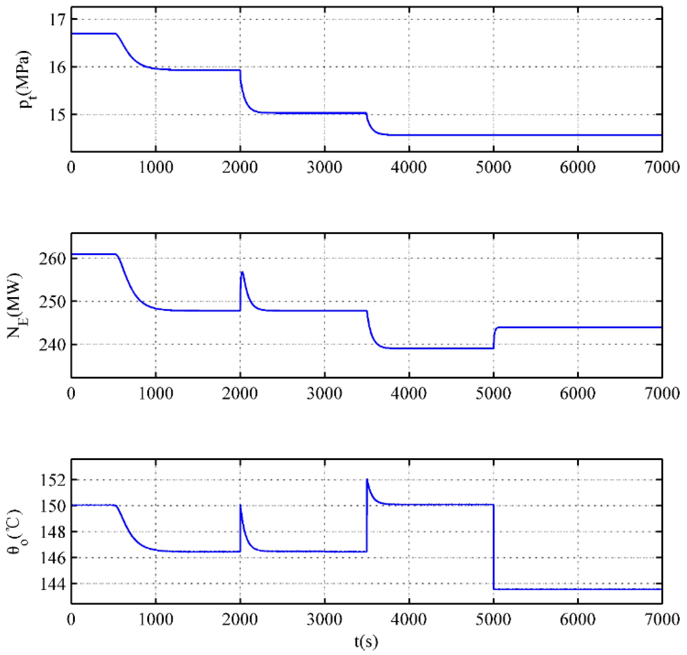
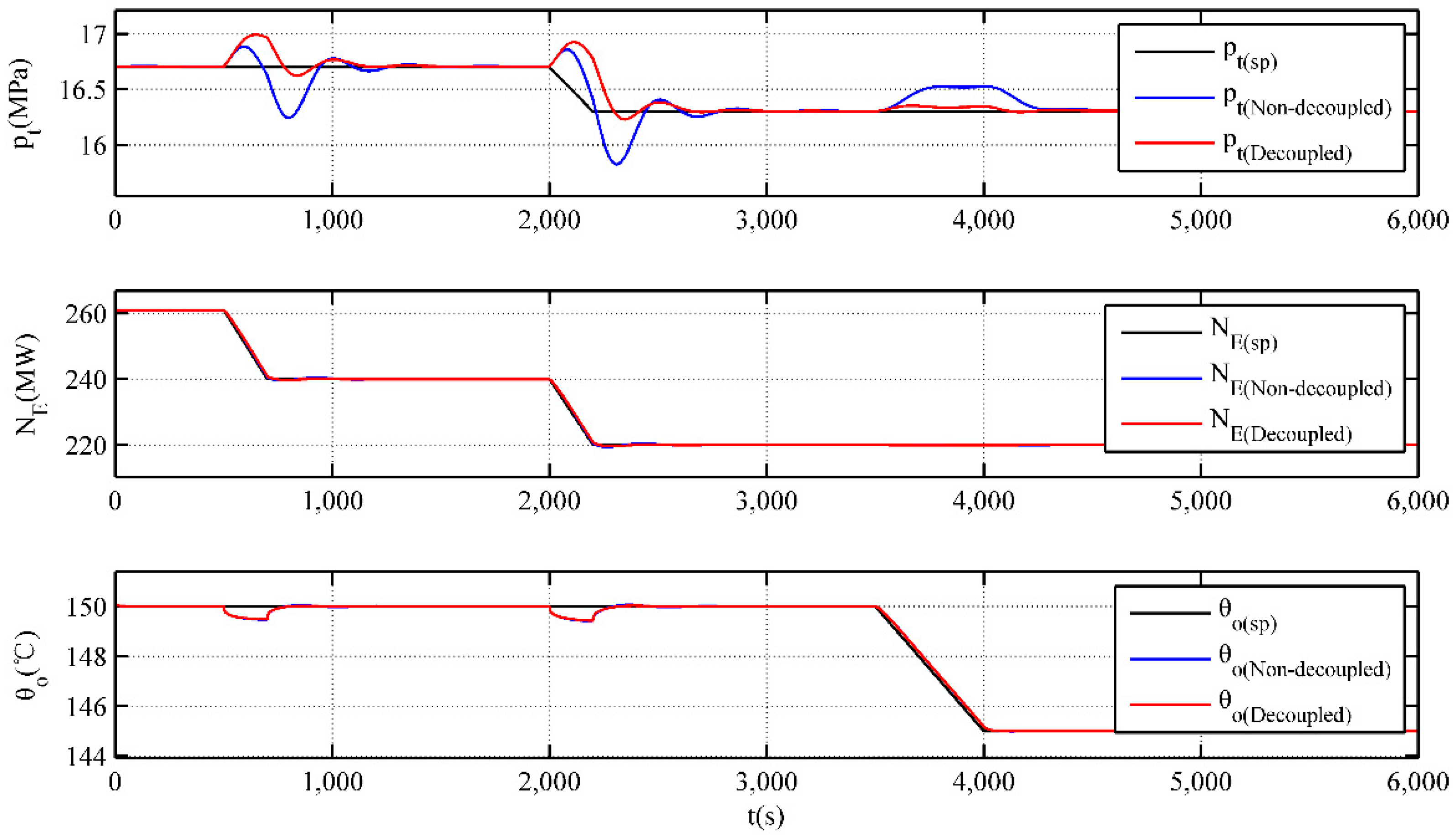
Figure 5 shows the curves for controlled variables. Under the decoupling control mode of high-pressure bypass, the fluctuating amplitude of controlled variables is reduced considerably, especially for that of the main steam pressure. It can be seen from the figure that although there is a certain delay in the response of the main steam pressure, it has almost no overshoot in the decoupled control mode, this is due to the compensation effect of the decoupling control of the high-pressure bypass, which allows the GPC controller to adjust the coal feed flow in advance, thereby increasing the capability of the control system to overcome external disturbances of the high-pressure bypass. In addition, since the response time for the other two controlled variables is short, the response values of the unit load and the supply water temperature can be closely matched to their set values.
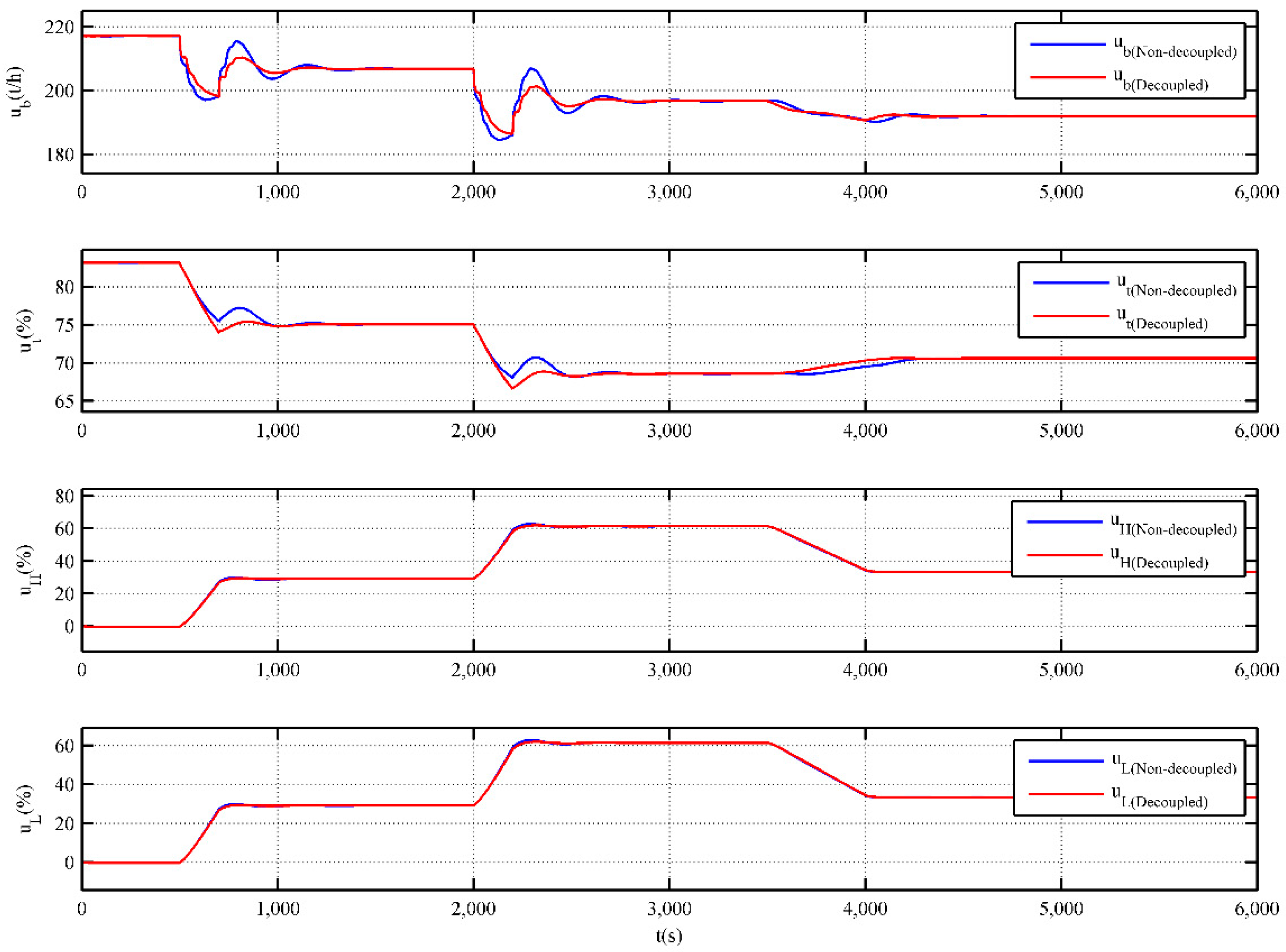
Figure 6 shows the curves for the control variables. It can be seen from the figure that the adjustment of each control variable is stable under the decoupling control mode of high-pressure bypass. In addition, compared with the non-decoupling control mode, the decoupling control can reduce the coal feed flow rapidly at the initial period of variable load and pull back it rapidly at the terminal period of variable load. This just validates the compensation effect of feedforward control and decoupling control.
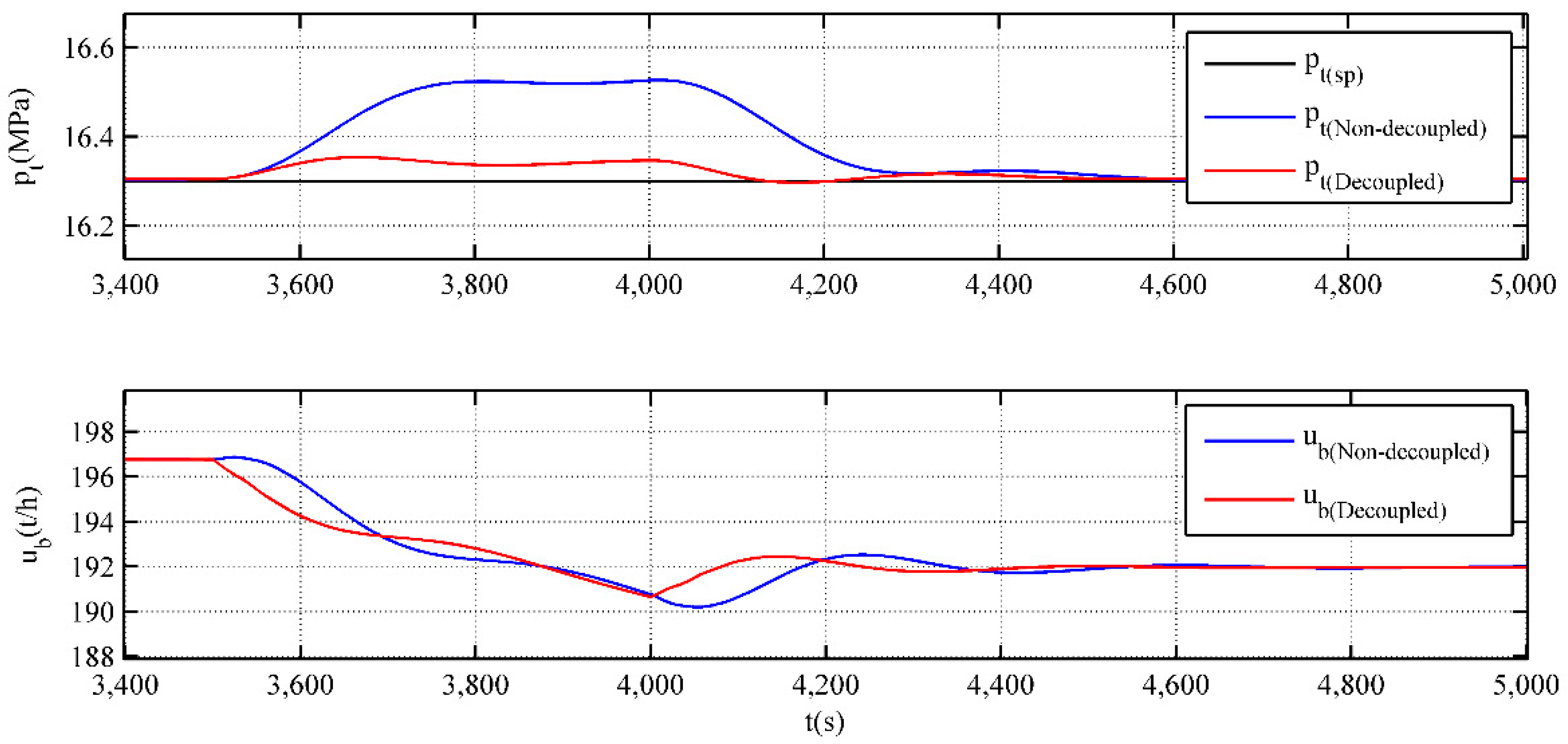
In order to further illustrate the effectiveness of the decoupling control of the high-pressure bypass, the curves of the main steam pressure and coal feed flow are enlarged and plotted in the same figure when the setting value of the supply water temperature changes at 3500 s (Figure 7). Since the setting values of the unit load and main steam pressure are unchanged during this period of simulation, the simulation verifies the effectiveness of the decoupling control well. It can be seen from the figure, due to the effect of the decoupling control, the coal feed flow drops rapidly at the initial period of the dynamic process, and in this case, the overshoot of the main steam pressure is greatly reduced, which fully proves that the decoupling control of the high-pressure bypass can improve the anti-disturbance capacity of the main steam pressure.
In addition, the integrated time and absolute error (ITAE) for each controlled variable are calculated (Table 4). It can be seen from the table that the ITAE indicators of the controlled variables are reduced to different degrees under the decoupling control mode, especially for that of main steam pressure. In this case, the proposed scheme can guarantee the safe, stable, and flexible operation of the unit.

6. Conclusions

Considering the effect of bypass heating on the energy balance of a CHP unit, a nonlinear dynamic model for a CHP unit with a two-stage bypass is proposed. The static parameters are determined via the design data of a CHP unit in northern China, and the dynamic parameters refer to model parameters of the same type of units in other references. On the basis of the model, an optimized control scheme for the coordination system of the unit is proposed. In this scheme, a stair-like feedforward-feedback predictive control algorithm is adopted to solve the control problem of large delays in boiler combustion, and the decoupling control is integrated to reduce the effect of external disturbance (the main steam valve and high-pressure bypass) on the main steam pressure. Simulation results indicate that the model effectively reflects the dynamics of the CHP unit with a two-stage bypass and can be used for designing and verifying its CCS; the control scheme can achieve optimal control of the CHP unit with a two-stage bypass; the compensation effect of feedforward and decoupling control allows the GPC controller to adjust the coal feed flow in advance; and in this case the coal feed flow can be reduced rapidly at the initial period of variable load and pulled back rapidly at the terminal period of variable load. Moreover, in the decoupling control of the high-pressure bypass mode, the fluctuation of the main steam pressure is considerably reduced and the adjustment of the coal feed flow is stable, which proves that the decoupling control of the high-pressure bypass can improve the anti-disturbance capacity of the main steam pressure. In this case, the proposed scheme can guarantee the safe, stable, and flexible operation of the unit and lay the foundation for decoupling the heat load-based constraint of CHP units, thereby expanding the access space of wind power in northern China.

Author Contributions

Conceptualization, Y.G. and Y.H.; methodology, Y.G.; Software, Y.G. and D.Z.; validation, Y.H., F.C. and J.L.; formal analysis, Y.G.; investigation, Y.H.; resources, D.Z.; data curation, F.C.; writing original draft, Y.G.; writing, review and editing, Y.H.; visualization, Y.G.; supervision, Y.G.; project administration, Y.H.; funding acquisition, D.Z.

Acknowledgments

This paper is supported by National Natural Science Foundation of China (51577160) and the Fundamental Research Funds for the Central Universities (2018ZD05).

Conflicts of Interest

The authors declare no conflict of interest.

Nomenclature

C b energy storage coefficient of drum, t/MPa P L P C i n inlet steam pressure of low-pressure cylinder, MPa
C t energy storage coefficient of main steam pipe, t/MPa, Q n e t , a r low calorific value of coal, MJ/kg
C r energy storage coefficient of reheat steam pipe, t/MPa, q m , b coal feed flow, t/h
C z energy storage coefficient of extraction pipe for intermediate-pressure cylinder, t/MPa, q m , m amount of coal entering the coal mill per unit time, t/h
D E main steam flow, t/h q m , f amount of coal entering the boiler per unit time, t/h
D R reheat steam flow, t/h q H T D P R i n cooling water flow via high-pressure bypass, t/h
D I P C o u t exhaust steam flow from intermediate-pressure cylinder, t/h q L T D P R i n cooling water flow via low-pressure bypass, t/h
D H extraction steam flow for heating, t/h q m , x circulating water flow in heat supply network, t/h
D L P C i n inlet steam flow of low-pressure cylinder, t/h T f inertia time of the milling process, s
D H T D P R i n steam flow via high-pressure bypass, t/h T t inertia time of turbine, s
D L T D P R i n steam flow via low-pressure bypass, t/h u H valve position of high-pressure bypass, %
N E electric power, MW u L valve position of low-pressure bypass, %
p b drum pressure, MPa u L P C i n valve position for heating, %
p t main steam pressure, MPa u t valve position of turbine, %
p 1 governing stage pressure, MPa θ i return water temperature in heat supply network, °C
p r reheat steam pressure, MPa θ o supply water temperature in heat supply network, °C
p H P C o u t exhaust steam pressure from high-pressure cylinder, MPa τ inertia time from coal feeder to coal mill, s
p I P C o u t exhaust steam pressure from intermediate-pressure cylinder, MPa K i pending static parameters, i = 1 , , 15

Appendix A

Figure A1. Heat balance diagram in turbine heat acceptance (THA) condition.
Energies 11 01395 g0a1
Figure A2. Heat balance diagram in rated heating (RH) condition.
Energies 11 01395 g0a2
Table A1. Performance parameters of boiler (boiler maximum continuous rating (BMCR); turbine rated load (TRL); turbine heat acceptance (THA)).
ItemsUnitBMCRTRLTHAHTO75% THA40% THA
Main steam flowt/h11001043.26997.56775.27714.46400.01
Outlet steam pressure of superheaterMPa17.5017.4117.3417.0516.988.08
Outlet steam temperature of superheater°C541541541541541530.1
Boiler pressureMPa19.018.7718.5917.8317.658.62
Reheat steam flowt/h909.19865.47829.81761.85606.49349.74
Inlet/outlet steam pressure of reheaterMPa4.053/3.8333.653/3.4433.699/3.4983.447/3.2632.689/2.5421.487/1.402
Inlet/outlet steam temperature of reheater°C336.8/541325.5/541327/541328.3/541302.1/541316.7/503
Feed water temperature°C284.2276.2277.8173.1257.1226.6
Table A2. Designed data of the two-stage bypass.
Device NameHigh-Pressure BypassLow-Pressure Bypass
Primary steamDesigned flow t/h175182
Designed pressure MPa17.64.8
Designed temperature °C546546
Operating pressure MPa7.851.35
Operating temperature °C523.8493.5
Secondary steamDesigned flow t/h208.5215
Designed pressure MPa4.80.49
Designed temperature °C355280
Operating pressure MPa1.50.2452
Operating temperature °C308.6240
Desuperheating water;Designed flow t/h33.533
Designed pressure MPa24.64.0
Designed temperature °C285140
Operating pressure MPa9.52
Operating temperature °C222.636.1
Table A3. Parameters of designed coal.
ItemsSymbolUnitDesigned CoalChecked Coal
Elemental analysisCarbon (received base)Car%38.5439.434
Hydrogen (received base)Har%3.253.53
Oxygen (received base)Oar%9.928.846
Nitrogen (received base)Nar%0.730.672
Sulfur (received base)St,ar%0.430.402
Industrial analysisAsh (received base)Aar%1519.802
Water (received base)Mt%32.427.54
Water (air-drying base)Mad%14.2012.142
Water (dry ash-free base)Vdaf%49.2843.512
Low calorific value of coal (received base)Qnet,arkcal/kg32283472
MJ/kg13.5014.522
Wearable coefficientHGI-5658.8

References

  1. National Energy Administration. Development of Wind Power Industry in 2015. Available online: http://www.nea.gov.cn/2016-02/02/c_135066586.htm (accessed on 10 May 2018).
  2. Tan, Z.F.; Ju, L.W. Review of China’s Wind Power Development: History, Current Status, Trends and Policy. J. North China Electr. Power Univ. 2013, 2, 2. [Google Scholar]
  3. Salem, R.; Bahadori-Jahromi, A.; Mylona, A.; Godfrey, P.; Cook, D. Comparison and Evaluation of the Potential Energy, Carbon Emissions, and Financial Impacts from the Incorporation of CHP and CCHP Systems in Existing UK Hotel Buildings. Energies 2018, 11, 1219. [Google Scholar] [CrossRef]
  4. Helin, K.; Zakeri, B.; Syri, S. Is District Heating Combined Heat and Power at Risk in the Nordic Area?—An Electricity Market Perspective. Energies 2018, 11, 1256. [Google Scholar] [CrossRef]
  5. Cozzolino, R. Thermodynamic Performance Assessment of a Novel Micro-CCHP System Based on a Low Temperature PEMFC Power Unit and a Half-Effect Li/Br Absorption Chiller. Energies 2018, 11, 315. [Google Scholar] [CrossRef]
  6. Zhang, G.; Cao, Y.; Cao, Y.; Li, D.; Wang, L. Optimal Energy Management for Microgrids with Combined Heat and Power (CHP) Generation, Energy Storages, and Renewable Energy Sources. Energies 2017, 10, 1288. [Google Scholar] [CrossRef]
  7. Rong, S.; Li, W.; Li, Z.; Sun, Y.; Zheng, T. Optimal Allocation of Thermal-Electric Decoupling Systems Based on the National Economy by an Improved Conjugate Gradient Method. Energies 2015, 9, 17. [Google Scholar] [CrossRef]
  8. Lv, Q.; Chen, T.; Wang, H.; Lv, Y.; Liu, R.; Li, W.D.; Huaneng, D.P.P. Review and Perspective of Integrating Wind Power into CHP Power System for Peak Regulation. Electr. Power 2013, 11, 129–136+. [Google Scholar]
  9. Northeast China Energy Regulatory Bureau of the National Energy Administration Special Reform Program for the Northeast Electric Power Auxiliary Service Market. Available online: http://dbj.nea.gov.cn/nyjg/hyjg/201611/t20161124_2580781.html (accessed on 24 May 2018).
  10. Northeast China Energy Regulatory Bureau of the National Energy Administration Northeast Electric Power Auxiliary Service Market Operation Rules (Trial). Available online: http://dbj.nea.gov.cn/nyjg/hyjg/201708/t20170817_3015219.html (accessed on 24 May 2018).
  11. National Energy Administration. The Pilot Project for Improving the Flexibility of Thermal Power Units Was Launched by the National Energy Administration. Available online: http://www.nea.gov.cn/2016-06/22/c_135456540.htm (accessed on 24 May 2018).
  12. Chen, X.; Kang, C.; O’Malley, M.; Xia, Q.; Bai, J.; Liu, C.; Sun, R.; Wang, W.; Li, H. Increasing the Flexibility of Combined Heat and Power for Wind Power Integration in China: Modeling and Implications. IEEE Trans. Power Syst. 2015, 30, 1848–1857. [Google Scholar] [CrossRef]
  13. Mathiesen, B.V.; Lund, H. Comparative Analyses of Seven Technologies to Facilitate the Integration of Fluctuating Renewable Energy Sources. IET Renew. Power Gener. 2009, 3, 190–204. [Google Scholar] [CrossRef]
  14. Streckienė, G.; Martinaitis, V.; Andersen, A.N.; Katz, J. Feasibility of CHP-plants with Thermal Stores in the German Spot Market. Appl. Energy 2009, 86, 2308–2316. [Google Scholar] [CrossRef]
  15. Lund, H.; Andersen, A.N. Optimal Designs of Small CHP Plants in a Market with Fluctuating Electricity Prices. Energy Convers. Manag. 2005, 46, 893–904. [Google Scholar] [CrossRef]
  16. Christidis, A.; Koch, C.; Pottel, L.; Tsatsaronis, G. The Contribution of Heat Storage to the Profitable Operation of Combined Heat and Power Plants in Liberalized Electricity Markets. Energy 2012, 41, 75–82. [Google Scholar] [CrossRef]
  17. Li, P.; Wang, H.; Lv, Q.; Li, W. Combined Heat and Power Dispatch Considering Heat Storage of Both Buildings and Pipelines in District Heating System for Wind Power Integration. Energies 2017, 10, 893. [Google Scholar] [CrossRef]
  18. Zhou, Y.; Wang, D.; Qi, T. Modelling, Validation and Control of Steam Turbine Bypass System of Thermal Power Plant. J. Control Eng. Appl. Inform. 2017, 19, 41–48. [Google Scholar]
  19. Pugi, L.; Galardi, E.; Lucchesi, N.; Carcasci, C. Hardware-in-the-loop Testing of Bypass Valve Actuation System: Design and Validation of a Simplified Real Time Model. Proc. Inst. Mech. Eng. Part E J. Process Mech. Eng. 2017, 231, 212–235. [Google Scholar] [CrossRef]
  20. Wang, D.; Zhou, Y.; Li, X. A Dynamic Model Used for Controller Design for Fast Cut Back of Coal-fired Boiler-turbine Plant. Energy 2018, 144, 526–534. [Google Scholar] [CrossRef]
  21. Zeng, D.L.; Zhao, Z.; Chen, Y.Q.; Liu, J.Z. A Practical 500MW Boiler Dynamic Model Analysis. Proc. CSEE 2003, 5, 33. [Google Scholar] [CrossRef]
  22. Åström, K.J.; Bell, R.D. Drum-boiler dynamics. Automatica 2000, 36, 363–378. [Google Scholar] [CrossRef]
  23. Tian, L.; Zeng, D.L.; Liu, J.Z.; Zhao, Z. A Simplified Nonlinear Dynamic Model of 330MW Unit. Proc. CSEE 2004, 24, 180–184. [Google Scholar] [CrossRef]
  24. Liu, J.Z.; Wang, Q.; Tian, L.; Liu, X.P. Simplified Model and Characteristic Analysis of Load-Pressure Object in Heat Supply Units. J. Chin. Soc. Power Eng. 2012, 3, 3. [Google Scholar]
  25. Liu, X.; Tian, L.; Wang, Q.; Liu, J. Simplified Nonlinear Dynamic Model of Generating Load-Throttle Pressure-Extraction Pressure for Heating Units. J. Chin. Soc. Power Eng. 2014, 34, 115–121. [Google Scholar]
  26. Clarke, D.W.; Mohtadi, C.; Tuffs, P.S. Generalized Predictive Control—Part I. The Basic Algorithm. Automatica 1987, 23, 137–148. [Google Scholar] [CrossRef]
  27. Clarke, D.W.; Mohtadi, C.; Tuffs, P.S. Generalized Predictive Control—Part II Extensions and interpretations. Automatica 1987, 23, 149–160. [Google Scholar] [CrossRef]
  28. Wu, G.; Peng, L.X.; Sun, D.M. Application of Stair-like Generalized Predictive Control to Industrial Boiler. In Proceedings of the IEEE International Symposium on Industrial Electronics, Xi’an, China, 25–29 May 1992; pp. 218–221. [Google Scholar]
  29. Xuefeng, Q.; Meisheng, X.; Demin, S.; Gang, W. The Stair-like Generalized Predictive Control for Main-steam Pressure of Boiler in Steam-power Plant. In Proceedings of the 3rd World Congress on Intelligent Control and Automation, Hefei, China, 26 June–2 July 2000; pp. 3165–3167. [Google Scholar]
  30. Li, X.; Wang, X.; Wang, Z.; Qian, F. A stair-like generalized predictive control algorithm based on multiple models switching. CIESC J. 2012, 1, 30. [Google Scholar] [CrossRef]
Figure 1. Schematic of a combined heat and power (CHP) unit with two-stage bypass.
Energies 11 01395 g001
Figure 2. Curves for model outputs.
Energies 11 01395 g002
Figure 3. Optimized control scheme for the CHP unit with two-stage bypass.
Energies 11 01395 g003
Figure 4. Control loop for main steam pressure.
Energies 11 01395 g004
Figure 5. Curves for controlled variables.
Energies 11 01395 g005
Figure 6. Curves for control variables.
Energies 11 01395 g006
Figure 7. Amplification curves of p t and u b .
Energies 11 01395 g007
Table 1. Extraction parameters of intermediate pressure cylinder (IPC) in normal operating condition.
p I P C o u t /MPa0.20.30.40.50.6
θ o /°C120.2133.5143.6151.8158.8
Table 2. Designed data of a CHP unit in China.
ParameterValueParameterValue
Electric power output, N E ( R G ) (MW)330Steam flow via low-pressure bypass, D L T D P R ( R H ) i n (t/h)208.50
Coal feed flow, q m , b ( R G ) (t/h)207.74Drum pressure, p b ( R H ) (MPa)18.57
Low calorific value of coal, Q n e t , a r (MJ/kg)14.522Main steam pressure, p t ( R H ) (MPa)16.70
Main steam flow, D E ( R G ) (t/h)997.56Governing stage pressure, p 1 ( R H ) (MPa)13.887
Reheat steam flow, D R ( R G ) (t/h)829.81Reheat steam pressure in cold section, p r ( R H ) (MPa)3.699
Exhaust steam flow from IPC, D I P C ( R G ) o u t (t/h)695.00Exhaust steam pressure from IPC, p I P C ( R H ) o u t (MPa)0.490
Main steam flow, D E ( R H ) (t/h)1043.26Inlet steam pressure of LPC, P L P C ( R H ) i n (MPa)0.157
Reheat steam flow, D R ( R H ) (t/h)860.27Cooling water flow via high-pressure bypass, q H T D P R ( R H ) i n (t/h)33.5
Exhaust steam flow from IPC, D I P C ( R H ) o u t (t/h)726.67Cooling water flow via low-pressure bypass, q L T D P R ( R H ) i n (t/h)33.0
Extraction steam flow for heating, D H ( R H ) (t/h)500Circulating water flow in heat supply network, q m , x ( R H ) (t/h)12,000
Inlet steam flow of low-pressure cylinder, D L P C ( R H ) i n (%)226.67Return water temperature from heat supply network, θ i ( R H ) (°C)40
Steam flow via high-pressure bypass, D H T D P R ( R H ) i n (t/h)175--
Table 3. Model parameters of a CHP unit with two-stage bypass.
K 1 = 0.3307 K 6 = 1.1914 K 11 = 14.4375 τ = 15 C I P C = 160
K 2 = 800.1323 K 7 = 0.5637 K 12 = 3.7865 × 10⁻⁴ T f = 120 T t = 12
K 3 = 0.7512 K 8 = 2.3257 K 13 = 0.3308 C b = 3300-
K 4 = 0.1050 K 9 = 0.8447 K 14 = 0.3977 C t = 20-
K 5 = 0.8246 K 10 = 1.1785 K 15 = 0.4748 C r = 10-
Table 4. Integrated time and absolute error (ITAE) indicator for each controlled variable.
IndicatorMain Steam Pressure (MPa)Unit Load (MW)Supply Water Temperature (°C)
Non-decoupling control3699.616290.313282.26
Decoupling control2209.685707.163112.17

