Article

Analytical Calculation for Multi-Infeed Interaction Factors Considering Control Modes of High Voltage Direct Current Links

School of Electric Power, South China University of Technology, Guangzhou 510640, China
*
Author to whom correspondence should be addressed.
Energies 2018, 11(6), 1506; https://doi.org/10.3390/en11061506
Submission received: 17 May 2018 / Revised: 1 June 2018 / Accepted: 6 June 2018 / Published: 8 June 2018

Abstract

:
The multi-infeed interaction factor (MIIF) is used extensively in indicating the degree of interaction among high-voltage direct current (HVDC) converters and is currently calculated by simulation methods according to the definition, or by using the equivalent impedance ratio method. The first method is an experimental calculation method and the second method does not account for the effects of HVDC control modes. An analytical calculation method for MIIF considering control modes of HVDC links is proposed in this paper. First, the voltage variation of converter bus in the context of small disturbance is equated by using the bus impedance matrix. In this way the equations for the solution of MIIF considering HVDC control mode are obtained. Subsequently, based on two rational assumptions, the practical analytical calculation expression of MIIF is deduced in detail. The MIIF calculation method proposed in this paper is an improvement of the equivalent impedance ratio method and reflects the main influencing factors of voltage interaction including HVDC control modes. Moreover, the derived analytical expression can give a fundamental insight into parameter dependencies of voltage interaction. Finally, the validity and accuracy of the proposed approach are demonstrated in both dual-infeed HVDC system and actual large-scale power grid.

1. Introduction

With the implementation of power transmission from West China to East China, more and more high-voltage direct current (HVDC) transmission projects have been putting into commercial operation in China recent years owing to its advantages in long distance and bulk power transmission with lower energy loss [1]. The complex multi-infeed AC/DC network structure has gradually been formed in the Eastern China, Southern China and other load centers [2,3]. Interactions can occur between AC system and multiple HVDC links at the same system, and become a serious problem faced by the receiving-end network in China.
Certain investigations indicate that the interactions among HVDC converters can negatively affect transient overvoltage, susceptibility to commutation failure, harmonic performance, and power/voltage instability [4,5,6]. Therefore, the investigation for interactions among multiple HVDC links is significantly important for the planning and operation of a large-scale AC/DC hybrid power system [7,8,9]. CIGRE working group proposes to employ multi-infeed interaction factor (MIIF) as an index to quantify the interactive influence among multiple HVDC links, and also suggests a method to calculate the value of MIIF by using MIIFij = ΔUiUj based on the definition [10]. This approach gives an accurate value for the MIIF. Due to the fact the value obtained relies heavily on the simulation results of the voltage variations ΔUi and ΔUj, it is an experimental calculation method and it cannot predict the MIIF value when the network structure or operation condition changes.
Several recent researches on MIIF found that the voltage interaction level depends on the system structure and parameters as well as characteristics of grid components, and the power characteristics of HVDC systems have a considerable effect. The analysis results of reference [11] show that the interaction level is related to network parameters and operation states of AC system, and power-voltage characteristics of a converter which depend on the control modes employed by a HVDC link. Reference [12] analyzes the influence mechanism of control modes with respect to voltage interaction and suggest that power-voltage sensitivity of the inverter is one of the main influencing factors. In [13], an analytical equivalent method for calculating MIIF based on the reduced Jacobian matrix of power flow is proposed; this method modifies the Jacobian matrix to obtain MIIF reflecting the effect of HVDC external characteristics on interaction. However, the MIIF expression derived by the method in [13] is complicated and non-intuitive, and it is difficult to analyze the various influencing factors of MIIF based on the expression itself.
To simplify the MIIF calculation, a method based on network impedance matrix has been proposed [14,15], which is an equivalent impedance ratio method. This method is presented in the form of a simple analytical expression: MIIFij = Zij/Zjj and can be used for fast calculation of MIIF. However, this method does not consider the effects of HVDC control modes and can only be used to study the impacts of the equivalent AC system parameters on MIIF. Since the HVDC control modes have a significant effect on voltage interaction [16,17], the usage of this method may cause large deviation under certain operation conditions. Consequently, it is necessary to improve the equivalent impedance ratio method to analyze easily. The impacts of HVDC control modes should be considered simultaneously.
To address this issue, this paper proposes an analytical calculation method for MIIF considering the control modes of HVDC links. First, the static equivalence of AC/DC power system based on the bus impedance matrix is presented, which reflects the effects of multi-infeed HVDC transmission systems on the converter bus voltage. On this basis, the voltage variations of different converter buses in the context of small disturbance are investigated. Subsequently, the MIIF solution equations considering HVDC control modes are deduced in detail. Based on these equations, the simplified conditions similar to the equivalent impedance ratio method for calculating MIIF are adopted. A practical MIIF analytical calculation method is obtained. This method is an improvement of the equivalent impedance ratio method and can effectively reflect the impacts of control modes on voltage interaction among HVDC links. Moreover, the proposed method can intuitively show the main influencing factors of voltage interaction and will make the parametric analysis of MIIF more convenient and effective compared to the simulation-based method.
The main contributions of this paper are summarized as follows:
(1)
The analytical expression for MIIF considering HVDC control modes is derived in detail based the static equivalent of AC/DC transmission systems and the small disturbance analysis of converter bus voltage.
(2)
By using the derived MIIF expression, the main influencing factors of voltage interaction are obtained and the parametric dependence of MIIF is analyzed.
(3)
The validity and accuracy of the proposed method are verified through both the dual-infeed HVDC system and the China Southern Power Grid.
The remainder of this paper is organized as follows: Section 2 briefly discusses the effect of multi-infeed HVDC links on converter bus voltage. Section 3 introduces voltage analysis indices and deduces the solving equations for MIIF in detail. Section 4 gives a practical calculation formula of MIIF based on the simplified conditions. Section 5 analyzes the MIIF parameter dependencies based on the obtained analytical expression. Section 6 shows case studies which validate the performance of the proposed method. Finally, Section 7 draws the conclusions of this paper.

2. Effect of Multi-Infeed HVDC on Converter Bus Voltage

For an AC/DC power system with n buses, the voltage of converter bus i can be expressed as:
U ˙ i = j = 1 n Z ˙ i j I ˙ j
where I ˙ j is the current injected into bus j, and Z ˙ i j is the transfer impedance between the bus i and j. Select a number of converter buses and label them as { 1 , ,   m } . The rest of buses are labeled as { m + 1 , ,   n } , and I ˙ j , other represents the current injection into the bus. The AC/DC power system can be equivalent to a two-bus equivalent model [18] as shown in Figure 1.
The equivalent parameters in Figure 1 are expressed as follows:
E ˙ i eq = j = m + 1 n Z ˙ i j I ˙ j , other
P i eq = P i + j = 1 j i m Z i j Z i i U i U j ( P j cos Φ i j Q j sin Φ i j )
Q i eq = Q i + j = 1 j i m Z i j Z i i U i U j ( Q j cos Φ i j + P j sin Φ i j )
Φ i j = δ i δ j + θ i i θ i j
where E ˙ i eq is the equivalent system voltage; P i eq and Q i eq are, respectively, the equivalent active and reactive power injected into converter bus i by the all HVDC subsystems; P i and Q i are, respectively, the active and reactive power injected into converter bus i by HVDC subsystem i; P j and Q j (with Q j including the reactive power supplied by reactive compensation devices at converter bus) are, respectively, the active and reactive power injected into converter bus j by HVDC subsystem j; U j is the voltage of bus j; Z i i is the self or driving-point impedance of bus i; Zij is the mutual impedance between bus i and j; θ i i and θ i j are, respectively, the impedance angles of Z ˙ i i and Z ˙ i j ; δ i and δ j are, respectively, the voltage phase angles of U ˙ i and U ˙ j .
Here, the HVDC system including reactive compensation devices is regarded as the equivalent power injection, and the AC system is regarded as the equivalent voltage source. When a disturbance is applied to bus j, the equivalent power injection and the equivalent system voltage at converter bus i will change, and the voltage of converter bus i will also change.

3. MIIF Considering HVDC Control Mode

The voltage analysis indices of multi-infeed HVDC system typically include voltage stability index (VSI), voltage sensitivity factor (VSF) and MIIF. These indices are obtained in the context of small disturbance and there is a close connection between them. The MIIF and VSF are adopted in this paper for analysis.

3.1. VSF

VSF is usually applied to analyze the voltage stability in power grids [19,20]. The definition of VSF is expressed as:
V S F i = Δ U i / Δ Q i
VSFi is essentially the ratio of voltage variation Δ U i with respect to power variation Δ Q i and represents the sensitivity of the voltage with respect to the reactive power injection at bus i. High ratio signifies even for a small reactive power disturbance causes a large change in the voltage magnitude which indicates the weakness of the bus.

3.2. MIIF

MIIF is an index to measure the degree of voltage interaction between DC converter buses proposed by CIGRE WG B4 Working Group [10]. The MIIF from converter j to converter i (MIIFij) is empirically defined by Equation (7) and is essentially the ratio of voltage drops at converter i and j due to a reactive power change at converter j:
M I I F i j = Δ U i / Δ U j
where Δ U i is the observed voltage drop at commutation bus i and Δ U j is an approximate 1% voltage reduction at commutation bus j caused by the artificial switched connection of a shunt reactive element. Obviously, the greater the MIIFij or MIIFji is, the stronger the interaction between converter bus i and converter bus j is, and vice versa.
When the external characteristics of power system components are neglected and the voltage amplitude and phase angle of each node are assumed to be the same, references [14,15] gives the equivalent impedance ratio method to calculate MIIF, given by:
M I I F i j = Z i j / Z j j
where Zjj is the self-impedance of the converter bus j in the bus impedance matrix; Zij is the mutual impedance between converter bus i and j. The bus impedance matrix can be obtained based on the static equivalent of receiving-end power system. Thereafter MIIF can be calculated by using Equation (8). However, this method does not take into account the control modes of HVDC systems and cannot be used to accurately calculate MIIFs under different control modes.

3.3. Analytical Derivation

To obtain the solution equations of MIIF considering HVDC control modes, the voltage variations of different converter buses in the context of small disturbance are analyzed. Only the effect of reactive power change on voltage is considered to simplify the calculation process. On this basis, the following calculation preconditions are given: (1) ignore the change of voltage phase angle after a small reactive power disturbance occurs; (2) the reactive power consumed by HVDC converters and transformers before the disturbance can be fully compensated locally by the reactive power compensators at converter bus.
There may be three and more HVDC links connected to the same AC system, but the simplified equivalent model of the entire AC/DC power system referred at bus i and j can be obtained by using the equivalent method in Section 2. The current injections at converter bus i and j are regarded as equivalent power injections. When a small reactive power disturbance Δ Q f j is applied to converter bus j, the equivalent reactive power injections at converter bus i and j are also changed. By analyzing the relationship between reactive power change and disturbance Δ Q f j , the relationship between disturbance and voltage change can be obtained. The incremental changes in equivalent reactive power injections into converter bus i and j are shown in the following figure.
In Figure 2, Δ Q i eq and Δ Q j eq are, respectively, the incremental changes in equivalent reactive power injections into converter bus i and j after disturbance. The following equations can be obtained from Figure 2.
Δ Q i eq = Δ Q i eq + k Δ Q f j
Δ Q j eq = Δ Q j eq + Δ Q f j
According to Equation (4), k can be expressed as:
k = Z i j U i Z i i U j c o s Φ i j
Before the disturbance occurs, the equivalent reactive power injection into converter bus i is:
Q i eq = Q i + Z i j Z i i U i U j ( Q j cos Φ i j + P j sin Φ i j )
Expanding Equation (12) by a full differential and ignoring the incremental change in voltage phase angle gives:
Δ Q i eq = Δ Q i + Q i eq U i Δ U i + Q i eq U j Δ U j + Q i eq P j Δ P j + Q i eq Q j Δ Q j
The partial derivatives in Equation (13) can be derived from Equation (4) as:
Q i e q U i = Z i j Z i i 1 U j P j sin Φ i j
Q i e q U j = Z i j Z i i U i U j 2 P j sin Φ i j
Q i e q P j = Z i j Z i i U i U j sin Φ i j
Q i e q Q j = Z i j Z i i U i U j cos Φ i j
When the external characteristics of HVDC systems are considered, the variations in Equation (13) can be expressed as:
Δ Q i = d Q i d U i d U i d U j d U j d Q f j Δ Q f j
Δ U i = d U i d U j d U j d Q f j Δ Q f j
Δ U j = d U j d Q f j Δ Q f j
Δ P j = d P j d U j d U j d Q f j Δ Q f j
Δ Q j = d Q j d U j d U j d Q f j Δ Q f j
where d P i / d U i , d Q i / d U i , d P j / d U i and d Q j / d U j are the sensitivities of the active power and reactive power injections into converter bus i and j with respect to the converter bus voltages. The values of these sensitivities can be determined by Equations (23) and (24) as:
d P m d U m = d P d m d U m ( m = i , j )
d Q m d U m = d Q dm d U m d Q c m d U m ( m = i , j )
where d P d m / d U m and d Q d m / d U m are the sensitivities of the active and reactive power injection into bus m by HVDC systems with respect to converter bus voltage, respectively. The values of sensitivities under different control modes can be obtained by the mathematical expressions given in [11,12]. d Q cm / d U m is the sensitivity of reactive power generated by the shunt reactive power compensator at the converter bus k with respect to converter bus voltage.
Substituting Equations (11), (13) and (18)–(21) into Equation (9), it is achieved that:
Δ Q i eq Δ Q f j = ( Q i eq Q j d Q j d U j + Q i eq P j d P j d U j + Q i eq U j ) V S F j ( d Q i d U i + Q i eq U i ) M I I F i j · V S F j + Q i eq Q j
Similarly, the equation for converter bus j can be obtained as:
Δ Q j eq Δ Q f j = ( Q j eq Q i d Q i d U i + Q j eq P i d P i d U i + Q j eq U i ) M I I F i j · V S F j ( d Q j d U j + Q j eq U j ) V S F j + 1
Equations (25) and (26) describe the relationships between the incremental changes in equivalent reactive power injections and reactive power disturbance. According to the definitions of VSF and MIIF, we obtain:
M I I F i j · V S F j = Δ U i Δ Q i eq Δ Q i eq Δ Q f j
V S F j = Δ U j Δ Q j eq Δ Q j eq Δ Q f j
where Δ U i / Δ Q i eq and Δ U j / Δ Q j eq represent the sensitivities of the voltages of converter bus i and j with respect to reactive power injections when HVDC external characteristics are not counted, respectively.
Equations (25)–(28) are the MIIF solution equations obtained in this paper; and the expression of MIIF can be obtained by concatenating these equations. In the following section, we give the simplification conditions and will suggest the concise solution of MIIF.

4. Simplification of MIIF Solution Method

4.1. Rationality Analysis of Assumptions

In the calculation of MIIF by using Equation (8), the aforementioned equivalent impedance ratio method ignores the impacts of control modes of HVDC systems and is also based on the following two assumptions: (a) the voltage amplitude and phase between two converter buses are approximately equal; (b) ignore the external characteristics of power system components other than HVDC links i and j. These two assumptions will also be adopted to simplify the solution of MIIF in this paper.
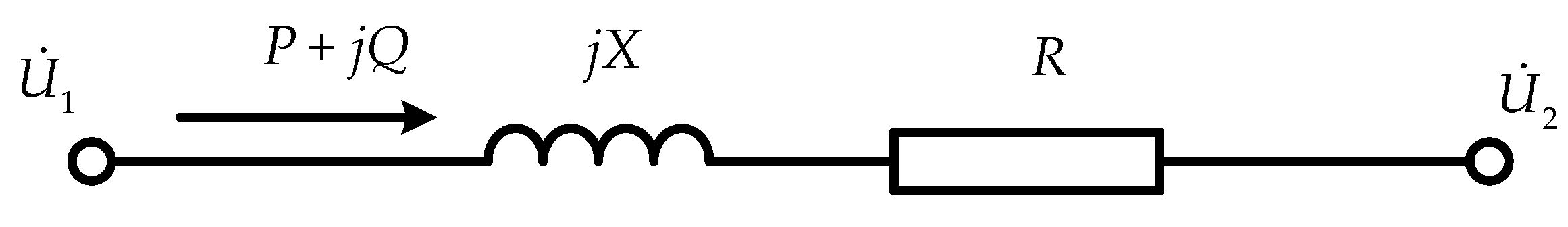
Here is the analysis of the rationality for the assumption (a). When HVDC system is in normal operation, the converter bus voltage is around its rated value, and the voltage amplitudes of two converter buses are approximately equal. The simplified lumped-parameter model of power system transmission line shown in Figure 3 can be applied to analyze the voltage phase angle difference between two converter buses.
In Figure 3, P + j Q is the transmitted power; R + j X is the line impedance; U ˙ 1 and U ˙ 2 are the sending-end voltage and receiving-end voltage of transmission line, respectively. For the transmission line with high voltage level, the horizontal component of voltage drop can be expressed as
δ U 1 P X U 1
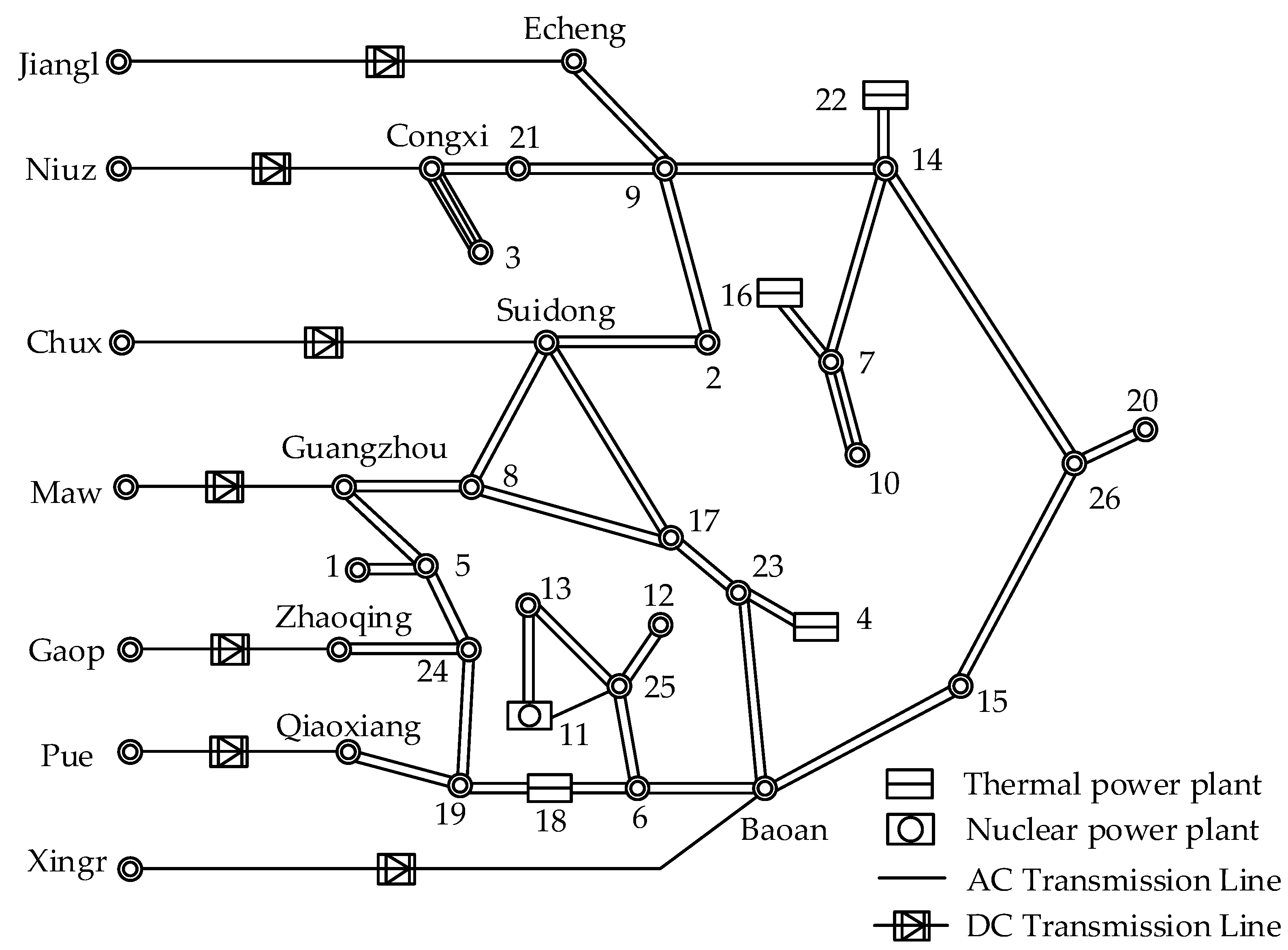
The horizontal component of voltage drop determines the voltage phase angle difference between the two buses. In the multi-feed HVDC system, different HVDC systems supply power to the same load region, and the difference of power flow (p.u.) between converter buses is quite small. Moreover, the stronger the interaction, the closer the electric distance between the HVDC links, and the voltage phase angle difference is also the smaller between two buses. In summary, the voltage phase angle difference is typically small between different converter buses in a multi-infeed configuration. For example, in case of large power flow in flood season in 2017, the China Southern Power Grid has seven HVDC links feeing into Guangdong power grid. The voltage phase angle differences between any two inverter buses are less than 6 degrees. Therefore, it can be regarded that the voltage phase angle difference between converter bus i and j is quite small actually. It can be seen that the assumption (a) has a strong applicability in multi-infeed HVDC transmission systems.
Here is the analysis of the rationality for the assumption (b). The assumption (b) is usually applied to simplify the analysis for the interaction between HVDC links. However, this simplification will bring some certain deviations when it comes to actual system calculations. One way to avoid deviations is to take full account of the effects of power system components when obtaining equivalent impedance parameters Zii, Zjj, and Zij. For example, the equivalent impedance parameters with full consideration of the effects of power system components can be obtained when online Thevenin equivalent is adopted [21,22].

4.2. Simplification Based on Assumptions

Based on assumption (a), the following relationships can be found:
U i U j ,   Φ i j 0 ,   Φ j i 0
By combining Equations (25)–(28) and Equation (30), a much more simple MIIF analytic expression can be obtained:
M I I F i j = Δ U i Δ Q i eq Z i j Z i i Δ U j Δ Q j eq ( 1 Δ U i Δ Q i eq d Q i d U i + Z i j 2 Z i i Z j j Δ U i Δ Q i eq d Q i d U i )
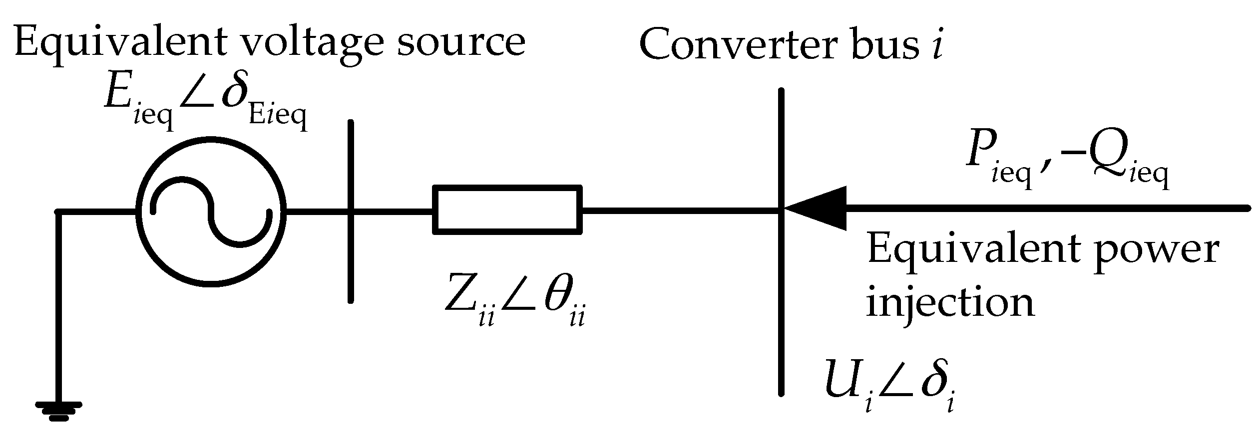
For the equivalent model shown as Figure 1, if there are two HVDC links in the same system, that is, the HVDC link i and j, the following equations can be obtained:
E ˙ i eq = k = 1 n Z ˙ i k I ˙ k , other
P i eq = P i + Z i j Z i i U i U j ( P j cos Φ i j Q j sin Φ i j )
Q i eq = Q i + Z i j Z i i U i U j ( Q j cos Φ i j + P j sin Φ i j )
According to assumption (a), under the rated conditions, it may be assumed that:
Φ i j = 0 ,   U i = U j = 1
Equations (33) and (34) can be rewritten as:
P i eq = P i + Z i j Z i i P j
Q i eq = Q i + Z i j Z i i Q j = 0
Subsequently, the relationship between Δ U i / Δ Q i eq and the equivalent parameter Zii will be deduced. In the equivalent system shown in Figure 1, voltage drop expression is represented as:
E i eq 2 = ( U i + U i ) 2 + δ U i 2
where:
U i = P i eq Z i i cos θ i i + Q i eq Z i i sin θ i i U i
δ U i = P i eq Z i i sin θ i i + Q i eq Z i i cos θ i i U i
represent, respectively, the vertical component and horizontal component of voltage drop.
According to assumption (b), the currents injected into buses by each component are maintained constant, so E ˙ i eq is constant. Combining Equations (38)–(40), it is achieved that:
d U i d Q i eq = Z i i sin θ i i + Q i eq 2 Z i i 2 U i 2 U i Q i eq 2 Z i i 2 + P i eq 2 Z i i 2 U i 3
Substituting Equations (35) and (37) into Equation (41), and simplifying gives:
d U i d Q i eq = Z i i sin θ i i 1 P i eq 2 Z i i 2
Then we obtain:
Δ U i Δ Q i eq = Z i i sin θ i i 1 P i eq 2 Z i i 2
Similarly, we have:
Δ U j Δ Q j eq = Z j j sin θ j j 1 P j eq 2 Z j j 2
According to Equations (43) and (44), the values of Δ U j / Δ Q j eq and Δ U i / Δ Q i eq can be obtained by power grid equivalent parameters easily. Further, the relation between Δ U j / Δ Q j eq and Δ U i / Δ Q j eq 
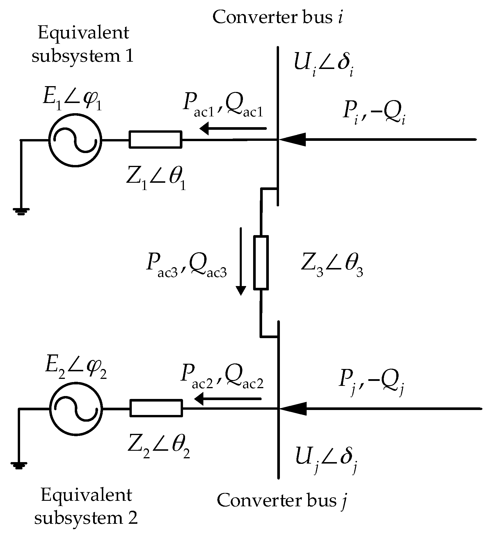
will be deduced. For the convenience of analysis, the equivalent model shown in Figure 1 is transformed into a simplified model of dual-infeed HVDC system as shown in Figure 4.
In Figure 4, E1 and E2 are equivalent system voltage; Z1 and Z2 are equivalent system impedances; Z3 is the tie-line equivalent impedance. The HVDC systems are simplified in the form of power injections into converter bus i and j. The corresponding relations of parameters between networks in Figure 1 and Figure 4 are as follows:
Z ˙ 1 = Z ˙ i i Z ˙ j j Z ˙ j j Z ˙ i j
Z ˙ 2 = Z ˙ i i Z ˙ j j Z ˙ i i Z ˙ i j
Z ˙ 3 = Z ˙ i i Z ˙ j j Z ˙ i j
E ˙ 1 = Z ˙ 1 + Z ˙ 3 Z ˙ 3 E ˙ i eq Z ˙ 1 Z ˙ 3 E ˙ j eq
E ˙ 2 = Z ˙ 2 + Z ˙ 3 Z ˙ 3 E ˙ j eq Z ˙ 2 Z ˙ 3 E ˙ i eq
According to assumption (b), E ˙ 1 and E ˙ 2 are constant. By combining assumption (a), under the rated conditions, it may be assumed that: δ 1 = δ 2 = 0 , U i = U j = 1 . Thus, there is no power transmitted through tie line (i.e., P ac 3 = 0 , Q ac 3 = 0 ); namely, there is no power exchange between the two sources, then E ˙ 1 = E ˙ 2 .Consequently, we have:
φ 1 δ i = φ 2 δ j
As a result, the voltage drops in the impedances of two equivalent subsystems are equal. According to the formula of voltage drop, it can be obtained as:
P i Z 1 = P j Z 2
Substituting Equations (36), (45) and (46) into Equation (51), it is achieved that:
P i eq Z i i = P j eq Z j j
Substituting Equation (52) into Equations (43) and (44), it is achieved that:
Δ U i Δ Q i eq / Δ U j Δ Q j eq = Z i i Z j j
In summary, based on the assumptions (a) and (b), the following two approximate equations can be obtained:
Δ U i Δ Q i eq Z i i sin θ i i 1 P i eq 2 Z i i 2
Δ U i Δ Q i eq / Δ U j Δ Q j eq Z i i Z j j
Substituting Equation (55) into Equation (31), the MIIF expression can be derived as:
M I I F i j = Z i j Z j j ( 1 Δ U i Δ Q i eq d Q i d U i + Z i j 2 Z i i Z j j Δ U i Δ Q i eq d Q i d U i ) 1
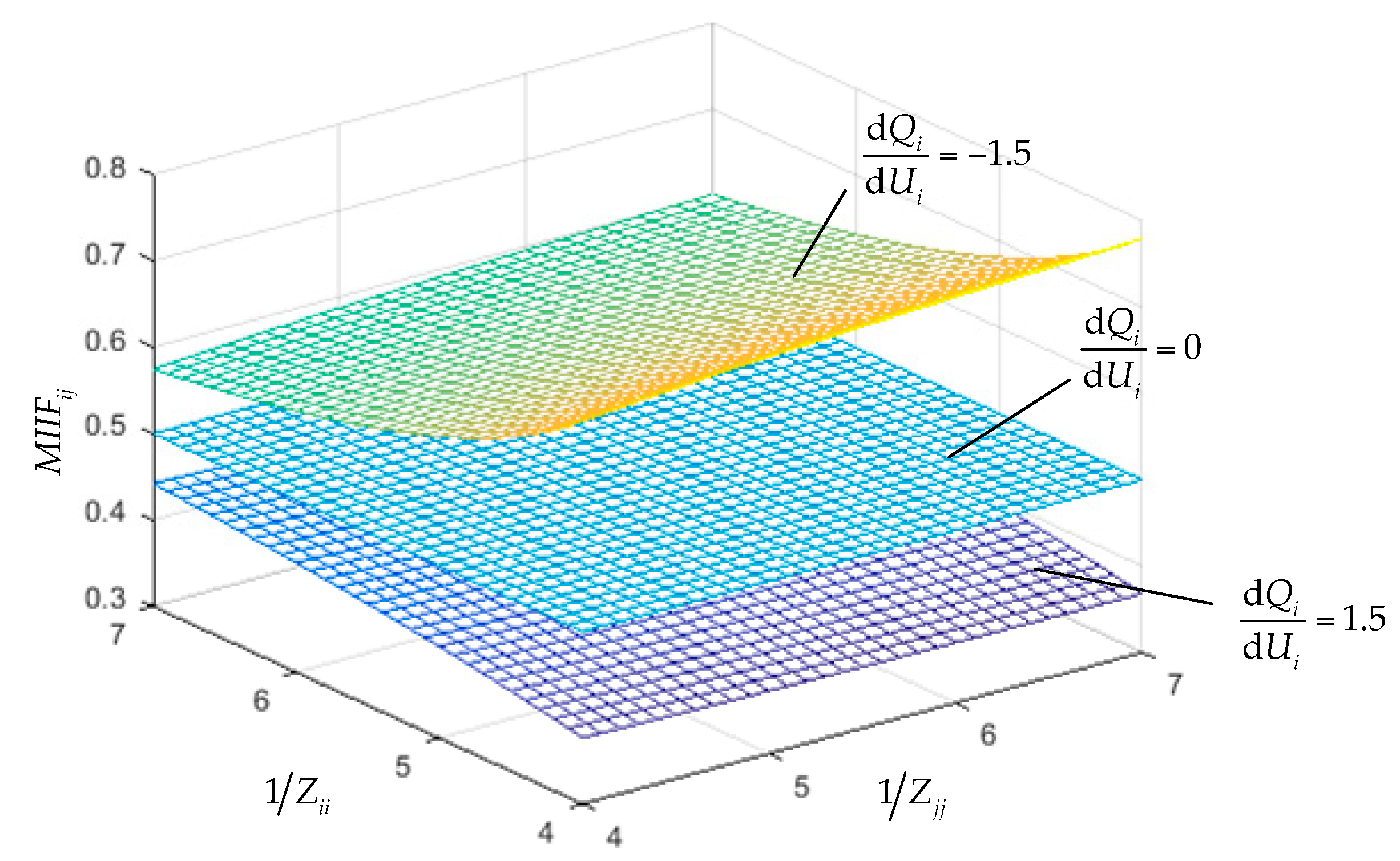
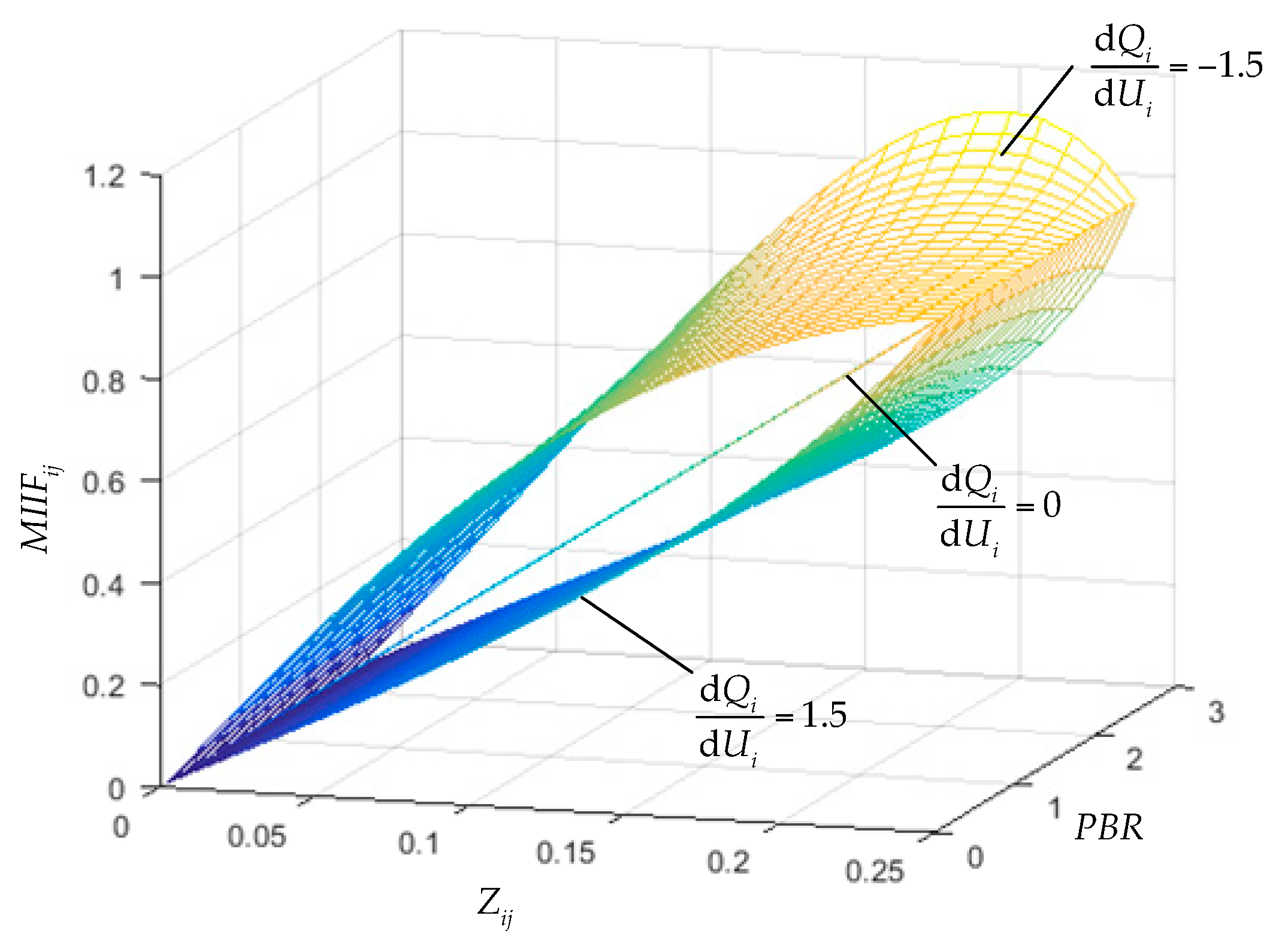
According to Equation (56), MIIF can be conveniently calculated, and it can simply and intuitively reflect the influence of various factors on the value of MIIF. It is obvious from Equation (56) that MIIFij is mainly related to the strength of AC system, the mutual impedance between converter buses, the capacities of two DC systems, and the control mode of HVDC link i. In above expression, MIIF is expressed as the product of the equivalent impedance ratio and a modified coefficient. Thus, Equation (56) is an improvement for the equivalent impedance ratio method and can effectively reflect the main influencing factors of MIIF including HVDC control modes.
In particular, if the system is sufficiently strong, then P i eq 2 Z i i 2 1 , and we have:
Δ U i Δ Q i eq Z i i
Similarly, for converter bus j, we have:
Δ U j Δ Q j eq Z j j
Substituting Equations (57) and (58) into Equation (56), MIIF is rewritten as:
M I I F i j = Z i j Z j j ( 1 + Z i i d Q i d U i Z i j 2 Z j j d Q i d U i ) 1
The above equation is a simplified version of Equation (56) under the certain circumstance, and it only comprises the reactive power sensitivity with respect to voltage and the equivalent impedance of AC system. 
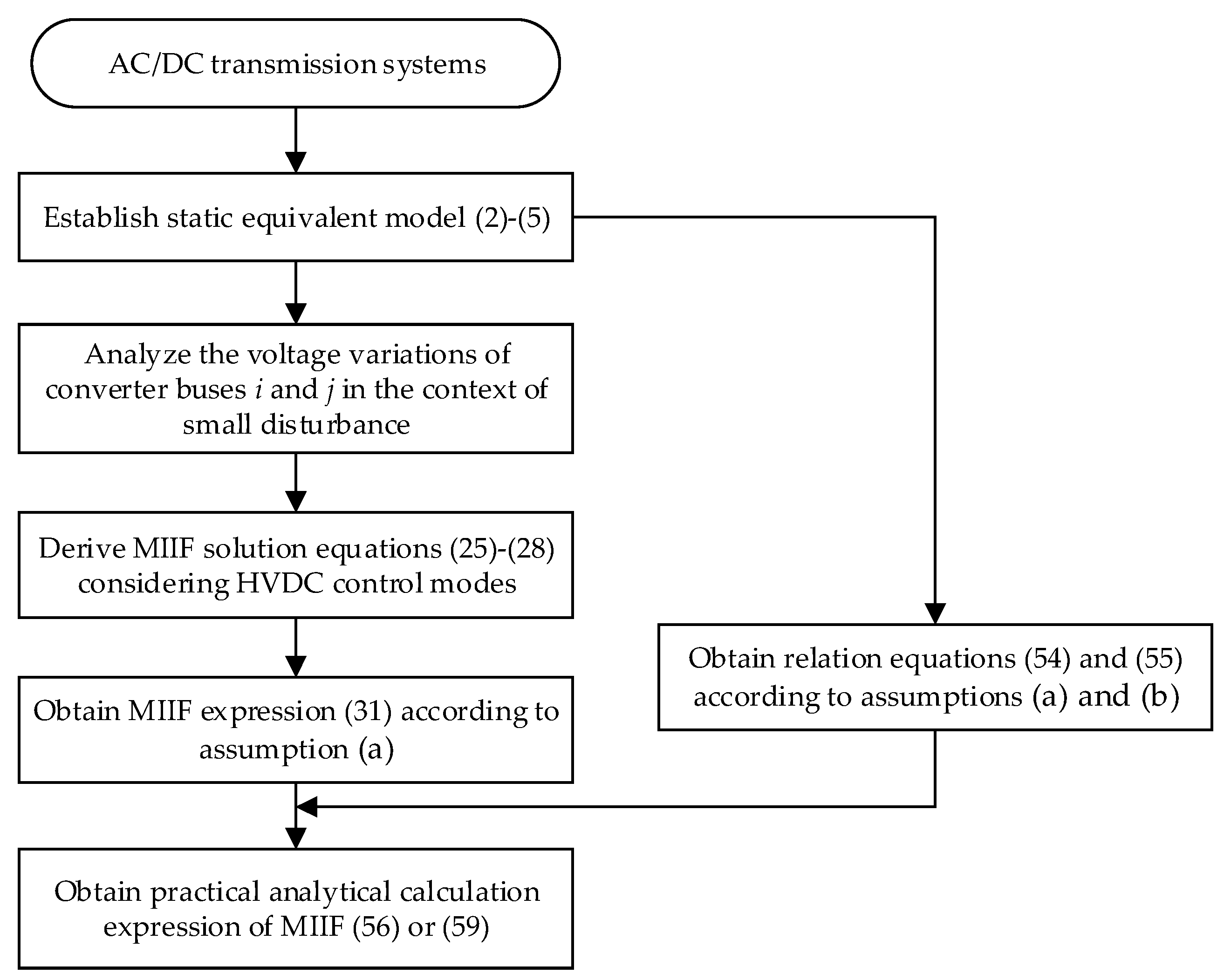
Figure 5 illustrates the overall process of the proposed analytical method for MIIF.

5. Parametric Analysis of MIIF

In this section, the parametric dependence of MIIF is analyzed using foregoing analytic derivation. The reactive power-voltage characteristics ( d Q i / d U i ) are used as an alternative to the control modes to analyze the impacts of the control modes on MIIF in Equation (56). Because of the different HVDC systems with different parameters, the reactive power-voltage characteristics of different HVDC systems are different when they operate in the same control mode. Therefore, the analysis of reactive power-voltage characteristics is more general than the analysis of control modes. The following parameter analysis is based on three different reactive power-voltage characteristics (i.e., d Q i / d U i = −1.5, 0, and 1.5 p.u.). When d Q i / d U i = 0 is used, it can be seen from Equation (56) that the MIIF calculation method proposed in this paper is the same as the equivalent impedance ratio method.

5.1. Self-Impedances

The inverses of self-impedances of bus i and j, which are 1/Zii and 1/Zjj, are varied from 4 to 7 p.u., while the value of Z i j / Z j j is maintained at 0.5 and the power ratings of HVDC links i and j are maintained constant (i.e., P d i = P d j = 1 p.u.).
As seen from Figure 6, when d Q i / d U i = 1.5 , MIIFij decreases significantly as 1/Zii increases and increases slightly as 1/Zjj increases. However, the change situation of MIIFij along with 1/Zii and 1/Zjj is just the opposite when d Q i / d U i = 1.5 . If the MIIFij calculated by the equivalent impedance ratio method is used as a reference, it can be noted from Equation (56) or Figure 5 that the MIIFij when d Q i / d U i < 0 is greater than that when d Q i / d U i > 0 for all Zii and Zjj. This implies that the control mode plays a role in increasing MIIF when d Q i / d U i < 0 and reducing MIIF when d Q i / d U i > 0 .

5.2. Power Base Ratio and Mutual Impedance

The power base ratio (PBR) P d j / P d i is the ratio of the power rating of the jth HVDC link and that of the referenced ith HVDC link. The power rating of HVDC link j ( P d j ) is varied between 0.1 to 2.5 while that of HVDC link i ( P d i ) is maintained constant. The mutual impedance Zij is varied from 0.01 to 0.25 p.u. while self-impedance Zii and Zjj are maintained constant (i.e., Z i i = Z j j = 0.25 ).
As seen from Figure 7, when d Q i / d U i = 1.5 , MIIFij increases with power base ratio. However, the change situation of MIIFij along with mutual impedance Zij is relatively complicated. In the case of Pdj less than 1.3 p.u., MIIFij increases with Zij. In the case of Pdj greater than 1.3 p.u., MIIFij first increases then decreases with increase of Zij. On the other hand, when d Q i / d U i = 1.5 , MIIFij decreases with power base ratio, but increases with mutual impedance.

6. Case Studies

In the previous sections, the equivalent impedance ratio method is improved to consider the impact of HVDC control modes; and the practical formula for calculating MIIF as shown in Equation (56) is obtained. In order to prove the correctness of the formula derivation process, the Equation (56) will be verified in a dual-infeed HVDC test system using PSCAD/EMTDC electromagnetic transient program and a real large system using PSD-BPA electromechanical transient program.

6.1. A Dual-Infeed HVDC System

Based on the PSCAD/EMTDC software, a simulation model for dual-infeed HVDC links in the same system is established. This system is obtained by extending the CIGRE HVDC benchmark model [23]. As shown in Figure 4, two HVDC links are connected at receiving-end AC system to form a dual-infeed HVDC system. The capacity and voltage of each HVDC subsystem are 1000 MW and 500 kV dc respectively. The receiving-end AC system is rated 230 kV. The detail system parameters are summarized in Appendix A. Different AC system strengths and inter-converter voltage interactions can be obtained by varying the AC system equivalent impedance magnitudes Z1, Z2 and the tie line impedance magnitude Z3.
Generally, one side of the HVDC link controls the DC voltage or the extinction angle and the other side controls the DC current or the DC power. The three most common combination control modes are as follows: the rectifier in constant current and the inverter in constant extinction angle control (CC-CEA), the rectifier in constant power and the inverter in constant extinction angle control (CP-CEA), the rectifier in constant current and the inverter in constant DC voltage control (CC-CDV). The active and reactive power sensitivities with respect to voltage can be calculated by using Equations (23) and (24) under different control modes. Also, simulation was conducted that a small inductive ground fault is applied and induced an approximate 1% voltage reduction at inverter bus; the simulation waveforms of voltage and power are represented in Figure 8 and Figure 9. The values of sensitivities obtained by formula and simulation method under three control modes are shown in Table 1. It can be seen from the Table 1 that the formula calculation results agree with the simulation results, which indicate that the formulas are valid.
The control mode of HVDC system j is CC-CEA, and the voltage of converter bus is operating under rated value. To facilitate the comparative study, the ratio of Zij and Zjj is maintained constant (i.e., Z i j / Z j j = 0.5 ) while the effective short-circuit ratio (ESCRj) at converter bus j maintained at 4 and the effective short-circuit ratio (ESCRi) at converter bus i varied from 3 to 6, which means that the MIIFij obtained by the equivalent impedance ratio method is always equal to 0.5 regardless of the values of ESCRi. In the case of different control modes of HVDC system i, the simulation calculation method based on definition and the analytic method proposed in this paper are used to calculate MIIFij with the ESCRi varied from 3 to 6, respectively. It is noted that the values of MIIF can be obtained by substituting the calculation results of sensitivities in Table 1 into Equation (56) when using the proposed analytical method. Table 2 shows the MIIF calculation results obtained by the three methods under different scenarios and the relative errors of the proposed analytic method and the equivalent impedance ratio method by means of simulation method as control group.
From Table 2, it can be seen that the method proposed in this paper can effectively reflect the impacts of different control modes on the value of MIIF and the calculation result is accurate. Compared with the other two control modes, the calculation results have a relative bigger deviation when using the control mode of CC-CEA. Because currently this paper only analyzes the influence of reactive power on voltage and ignores the effect of active power on voltage. It can be observed from Table 1 that the sensitivities of the active power to the voltage are almost zero when using the control mode of CP-CEA or CC-CDV, which means that MIIF only depends on the DC converter reactive power-voltage characteristics and is independent of active power-voltage characteristics. But the active power is sensitive to the voltage under the control mode of CC-CEA, which means that the disturbance has a considerable impact on the active power injected into converter bus. For the equivalent impedance ratio method, the calculation results are maintained at 0.5 under various control modes, and relatively close to actual value under the control mode of CC-CEA. However, for other control modes, the usage of the equivalent impedance ratio method will bring greater deviation.

6.2. China Southern Power Grid

The accuracy of the method proposed in this paper is verified in a real large system. Base on the BPA data of China Southern Power Grid (CSG) in case of large power flow in flood season, the simulation model of multiple HVDC links in the same system is established. This model has seven HVDC links feeding into Guangdong load center, and the DC terminal locations are as follows: Suidong, Qiaoxiang, Congxi, Zhaoqing, Guangzhou, Baoan and Echeng. The voltage levels and transmitted powers of all HVDC transmission lines are listed in Table 3. Due to the complex structure and large scale of this grid model, the data of four converter stations as Suidong, Qiaoxiang, Congxi and Zhaoqing is chosen to study here. Figure 10 shows the sketch map of multi-infeed configuration in Guangdong grid in 2017.
Under the control modes of CC-CEA and CP-CEA, the definition-based simulation method and the analytic method proposed in this paper are used to calculate MIIF. The relative errors between these two methods by means of simulation method as control group are also computed. The larger value of relative errors in both control modes is filled into the “Errors” column in Table 4.
According to the calculation results of the actual large-scale power grid case in Table 4, the proposed method has 1% to 15% relative error under the comprehensive effects of the power system components. In the simulation method, the full responses of power system components, including the detail element models, are taken into account. However, in the analytic method proposed in this paper, the external characteristics of power system components besides HVDC systems are ignored. But the calculated values of MIIF can generally reflect the degree of interaction between two HVDC links under different control modes. Thus, it can be used to estimate the value of MIIF for large-scale AC/DC transmission systems at planning stage or when the calculation accuracy demand is not very high.

7. Conclusions

This paper presented a new analytical method to calculate MIIF considering control modes of HVDC links. The analytical expression of MIIF was derived based on the static equivalent of AC/DC transmission systems and the small disturbance analysis of converter buses voltage. The obtained analytical expression is concise and intuitive, and can reflect the main influencing factors of MIIF, including the strength of AC systems, the mutual impedance between converter buses, HVDC systems capacity and control modes. The validity and accuracy of the proposed method were verified in a dual-infeed HVDC test system and the CSG system. The simulation results demonstrated that the proposed method can effectively reflect the impacts of different control modes on voltage interactions.
The proposed method is an improvement of the equivalent impedance ratio method, which can quickly calculate MIIF under different control modes of HVDC links. By using the derived analytical expression, the impacts of ac and dc side system parameters on voltage interactions between two converters can be determined effectively, and some quantitative studies on MIIF will be conducted conveniently. Therefore, the efficient approach proposed in this paper can be widely utilized in planning, design and stable operation of AC/DC hybrid power systems, and also can guide directions for improving the interaction characteristics between HVDC links.

Author Contributions

C.X., X.H. and Z.W. proposed the improved calculation method of multi-infeed interaction factor considering HVDC control modes; C.X. and Z.W. performed the experiments; X.H. and Z.H. analyzed the data; All authors discussed the results and contributed to writing the paper.

Acknowledgments

This research work is supported in part by the National Natural Science Fund of China-State Grid Joint Fund for Smart Grid (U1766213), in part by the Science and Technology Project of China Southern Power Grid (ZBKJXM20170071).

Conflicts of Interest

The authors declare no conflict of interest.

Nomenclature

MIIFijMulti-infeed interaction factor between bus i and j
Ui, ΔUiVoltage magnitude and voltage deviation at bus i
Zii, ZjjSelf-impedances of bus i and j
ZijMutual impedance between bus i and j
I ˙ j Current injected into bus j
E ˙ i eq Electric potential of equivalent voltage source i
Pi, −QjActive and reactive power injected into bus i by HVDC subsystem i
Pieq, −QieqEquivalent active and reactive power injected into bus i
δ i , δ j Angles of bus voltage Ui and Uj
θ i i , θ i j Angles of self-impedance Zii and mutual impedance Zij
VSFiVoltage sensitivity factor of bus i
ΔQiReactive power variation at bus i
ΔPj, ΔQjActive and reactive power variations at bus j
ΔQfjSmall reactive power disturbance applied to bus j
Δ Q i eq , Δ Q j eq Incremental changes in equivalent reactive power injection into bus i and j caused by disturbance at bus j
QcmReactive power generated by shunt reactive compensators at bus m
R, XResistance and reactance of transmission line
δ U , U Horizontal component and vertical component of voltage drop
Z1, Z2System impedances of equivalent subsystem 1 and 2
Z3Tie line impedance between equivalent subsystem 1 and 2
Pd, QdDC transmission active and reactive power
ESCRiEffective short-circuit ratio of bus i

Appendix A

Table A1. DC side parameters of dual-infeed HVDC system.
ParametersValues
Voltage Level (kV)500
Transmitted Power (MW)1000
DC Line Resistance (Ω)5.0
DC Line Inductance (H)1.194
Table A2. AC side parameters of dual-infeed HVDC system.
ParametersRectifierInverter
Voltage Level (kV)345230
System Frequency (Hz)5050
Filters and Capacitors (MVAR)11th harmonic252252
13th harmonic252252
Capacitors125125
Transformers (Each)Voltage Ratio (kV)345/213.5230/209.2
Capacity (MVA)603.73591.79
Impedance (p.u.)0.180.18

References

  1. Li, X.; Li, F.; Chen, S.; Li, Y.; Zou, Q.; Wu, Z.; Lin, S. An improved commutation prediction algorithm to mitigate commutation failure in high voltage direct current. Energies 2017, 10, 1481. [Google Scholar] [CrossRef]
  2. Huang, D.C.; Shu, Y.B.; Ruan, J.J.; Hu, Y. Ultra high voltage transmission in China: Developments, current status and future prospects. Proc. IEEE 2009, 97, 555–583. [Google Scholar] [CrossRef]
  3. Liao, S.W.; Yao, W.; Ai, X.M.; Wen, J.Y.; Liu, Q.; Jiang, Y.H.; Zhang, J.; Tu, J.Z. An improved multi-infeed effective short-circuit ratio for AC/DC power systems with massive shunt capacitor installed. Energies 2017, 10, 396. [Google Scholar] [CrossRef]
  4. Chen, X.Y.; Gole, A.M.; Han, M.X. Analysis of mixed inverter/rectifier multi-infeed HVDC systems. IEEE Trans. Power Deliv. 2012, 27, 1565–1573. [Google Scholar] [CrossRef]
  5. Toledo, P.F.; Pan, J.P.; Srivastava, K.; Wang, W.; Hong, C. Case study of a multi-infeed HVDC system. In Proceedings of the Joint International Conference on Power System Technology and IEEE Power India Conference, New Delhi, India, 12–15 October 2008; pp. 1–7. [Google Scholar]
  6. Xiao, H.; Li, Y.; Zhu, J.; Duan, X.Z. Efficient approach to quantify commutation failure immunity levels in multi-infeed HVDC systems. IET Gener. Transm. Distrib. 2016, 10, 1032–1038. [Google Scholar] [CrossRef]
  7. Karawita, C.; Annakkage, U.D. Multi-infeed HVDC interaction studies using small-signal stability assessment. IEEE Trans. Power Deliv. 2009, 24, 910–918. [Google Scholar] [CrossRef]
  8. Hwang, S.; Lee, J.; Jang, G. HVDC-system-interaction assessment through line-flow change-distribution factor and transient-stability analysis at planning stage. Energies 2016, 9, 1068. [Google Scholar] [CrossRef]
  9. Rahimi, E.; Gole, A.M.; Davies, J.B.; Fernando, I.T.; Kent, K.L. Commutation failure analysis in multi-infeed HVDC systems. IEEE Trans. Power Deliv. 2011, 26, 378–384. [Google Scholar] [CrossRef]
  10. CIGRE Working Group B4.41. Systems with Multiple DC Infeed. Available online: http://b4.cigre.org/Publications/Technical-Brochures/TB-364-2008-WG-B4.41-Systems-with-multiple-DC-Infeed (accessed on 5 April 2018).
  11. Liu, D.F.; Shi, D.Y.; Li, Y.H. A new definition of short-circuit ratio for multi-converter HVDC systems. J. Electr. Eng. Technol. 2015, 10, 1958–1968. [Google Scholar] [CrossRef]
  12. Chen, X.Y.; Han, M.X.; Liu, C.R. Impact of control modes on voltage interaction between multi-infeed AC-DC system. Autom. Electr. Power Syst. 2012, 36, 58–63. [Google Scholar]
  13. Aik, D.L.H.; Andersson, G. Analysis of voltage and power interactions in multi-infeed HVDC systems. IEEE Trans. Power Deliv. 2013, 28, 816–824. [Google Scholar] [CrossRef]
  14. Aik, D.L.H. Voltage and Power Interactions in Multi-Infeed HVDC Systems. Available online: http://www.eeh.ee.ethz.ch/uploads/tx_ethpublications/Voltage_and_Power_Interaction_Report.pdf (accessed on 29 March 2018).
  15. Rahimi, E. Voltage Interaction and Commutation Failure Phenomena in Multi-Infeed HVDC Systems. PH.D. Thesis, University of Manitoba, Winnipeg, MB, Canada, 2011. [Google Scholar]
  16. Zhao, K.; Yang, D.; Liu, Y. A new definition of multi-infeed short circuit ratio considering control modes of DC system. In Proceedings of the 2015 International Power, Electronics and Materials Engineering Conference, Dalian, China, 16–17 May 2015; pp. 551–556. [Google Scholar]
  17. Guo, X.J.; Guo, J.B.; Wang, C.S. Practical calculation method for multi-infeed short circuit ratio influenced by characteristics of external characteristics of DC system. Proc. CSEE 2015, 35, 2143–2151. [Google Scholar]
  18. Aik, D.H.; Andersson, G. An equivalent single-infeed model of multi-infeed HVDC systems for voltage and power stability analysis. IEEE Trans. Power Deliv. 2016, 31, 303–312. [Google Scholar]
  19. Guo, Q.; Yoon, M.; Kim, C.; Jang, G. Commutation failure and voltage sensitivity analysis in a hybrid multi-infeed HVDC system containing modular multilevel converter. Int. Trans. Electr. Energ. Syst. 2016, 26, 2259–2271. [Google Scholar] [CrossRef]
  20. Kishore, C.; Ghosh, S.; Karar, V. Symmetric fuzzy logic and IBFOA solutions for optimal position and rating of capacitors allocated to radial distribution networks. Energies 2018, 11, 776. [Google Scholar] [CrossRef]
  21. Abdelkader, S.M.; Morrow, D.J. Online Thevenin equivalent determination considering system side changes and measurement errors. IEEE Trans. Power Syst. 2015, 30, 2716–2725. [Google Scholar] [CrossRef]
  22. Arefifar, S.A.; Xu, W. Online tracking of power system impedance parameters and field experiences. IEEE Trans. Power Deliv. 2009, 24, 1781–1788. [Google Scholar] [CrossRef]
  23. Atighechi, H.; Chiniforoosh, S.; Jatskevich, J.; Davoudi, A.; Martinez, J.A.; Faruque, M.O.; Sood, V.; Saeedifard, M.; Cano, J.M.; Mahseredjian, J.; et al. Dynamic average-value modeling of CIGRE HVDC benchmark system. IEEE Trans. Power Deliv. 2014, 29, 2046–2054. [Google Scholar] [CrossRef]
Figure 1. Two-bus equivalent model of the n-bus AC/DC power system.
Energies 11 01506 g001
Figure 2. Schematic diagram of the change of reactive power at converter bus. (a) the change of reactive power at converter bus i; (b) the change of reactive power at converter bus j.
Energies 11 01506 g002
Figure 3. Simplified model of transmission line.
Energies 11 01506 g003
Figure 4. Simplified model of the dual-infeed HVDC system.
Energies 11 01506 g004
Figure 5. Flow chart of the overall process of the proposed method.
Energies 11 01506 g005
Figure 6. MIIF versus the inverses of self-impedances.
Energies 11 01506 g006
Figure 7. MIIF versus power base ratio and mutual impedance.
Energies 11 01506 g007
Figure 8. Voltage change of converter bus under different control modes.
Energies 11 01506 g008
Figure 9. Change of power injection into converter bus under different control modes. (a) active power; (b) reactive power.
Energies 11 01506 g009
Figure 10. Sketch map of multi-infeed HVDC system in Guangdong grid in 2017.
Energies 11 01506 g010
Table 1. Sensitivity calculation results of the CIGRE benchmark HVDC test model under three control modes.
Control ModesdPi/dUidQi/dUi
FormulaSimulationFormulaSimulation
CC-CEA1.0891.085−0.803−0.812
CP-CEA00−1.665−1.659
CC-CDV001.1521.158
Table 2. Comparison of MIIF obtained from three methods.
Control ModesESCRiSimulation MethodAnalytic MethodError 1Error 2
CC-CEA30.5310.5503.58%5.84%
40.5150.5292.72%2.91%
50.5110.5201.76%2.15%
60.5070.5131.18%1.38%
CP-CEA30.7770.7621.93%35.65%
40.6350.6451.57%21.26%
50.5930.5950.34%15.68%
60.5620.5681.07%11.03%
CC-CDV30.3420.3322.92%46.19%
40.3790.3721.85%31.93%
50.3980.4010.75%25.63%
60.4190.4220.72%19.33%
(1) The values of MIIFij obtained by the equivalent impedance ratio method are maintained at 0.5 under different scenarios. (2) Error 1: the error of proposed analytic method; and Error 2: the error of equivalent impedance ratio method.
Table 3. HVDC transmission lines in the China Southern Power Grid.
HVDC TransmissionVoltage Level (kV)Transmitted Power (MW)Line Length (km)Terminal Location
Chusui±80050001373Suidong
Puqiao±80050001441Qiaoxiang
Niucong±50064002 × 1268Congxi
Gaozhao±5003000891Zhaoqing
Tianguang±5001800963Guangzhou
Xingan±50030001194Baoan
Sanguang±5003000940Echeng
Table 4. Calculation results of actual system.
Converter Station iConverter Station jControl Modes of HVDC System iErrors
CC-CEACP-CEA
Simulation MethodAnalytic MethodSimulation MethodAnalytic Method
SuidongQiaoxiang0.1170.1100.1370.12211%
Congxi0.2750.2730.3050.3011%
Zhaoqing0.1760.1630.1970.1818%
QiaoxiangSuidong0.1100.1230.1280.13912%
Congxi0.0970.0990.1130.1122%
Zhaoqing0.2500.2680.2620.30115%
CongxiSuidong0.3240.3430.3660.40511%
Qiaoxiang0.1170.1110.1400.1335%
Zhaoqing0.2220.2120.2490.2535%
ZhaoqingSuidong0.2200.2100.2390.2285%
Qiaoxiang0.2970.3080.3120.3337%
Congxi0.2310.2180.2480.2366%

