Article

The Integrated Switching Control Strategy for Grid-Connected and Islanding Operation of Micro-Grid Inverters Based on a Virtual Synchronous Generator

School of Electrical and Information Engineering, Jiangsu University, Zhenjiang 212000, China
*
Author to whom correspondence should be addressed.
Energies 2018, 11(6), 1544; https://doi.org/10.3390/en11061544
Submission received: 22 May 2018 / Revised: 6 June 2018 / Accepted: 12 June 2018 / Published: 13 June 2018

Abstract

:
In allusion to the virtual synchronous generator (VSG)-based voltage source inverters in micro-grids, an integrated control method combining a quasi-synchronization algorithm and an islanding detection algorithm is proposed to improve the power supply reliability and quality, which can simultaneously meet the operational requirements of both grid-connected mode (GCM) and off-grid mode (OGM), and the smooth switching between them. The quasi-synchronization algorithm of the micro-grid inverter is designed to realize a flexible grid connection. Moreover, for quickly detecting islanding phenomena, a novel islanding detection algorithm based on the VSG’s inherent characteristics is put forward. Finally, the validity and availability of the proposed models and control strategies are comprehensively verified by simulation results based on Matlab/Simulink.

1. Introduction

Micro-grids, integrating distributed power supply, energy storage devices, power electronic equipment and local loads, is a new way of supplying power [1]. The switching control between grid connected mode (GCM) and off-grid mode (OGM) will directly affect the security and stability of the micro-network. Therefore, higher requirements are imposed on the control of switching between different operating modes of micro-grids [2].
The switching modes include both active and passive switching from GCM to OGM, as well as the active switching from OGM to GCM. In this regard, some control strategies have been proposed. P-Q control in GCM and V-F control in OGM, respectively proposed in [3,4], have the advantages of flexible control of the inverter and convenient adjustment. However, these control methods ignore the inertia characteristics of the synchronous generator (SG). Thus, VSG technology, similar to the operating mechanism and external characteristics of the SG, is proposed in [5,6,7,8]. In order to realize the active switching from OGM to GCM, the voltage amplitude, frequency and phase angle of the micro-grid system are adjusted to achieve the quasi-synchronous grid-connected operation in [9]. Based on synchronous adjustment of the frequency, to ensure the same phase of the micro-grid system voltage and the grid voltage, the cross-calculation algorithm is proposed in [10,11]. The combination of traditional inverter synchronization method and VSG is proposed in [12,13], by introducing voltage, frequency, and phase angle regulators to achieve inverter pre-synchronization. In the quasi-synchronous grid-connected methods proposed above, the information of the grid voltage and the micro-grid voltage can be obtained through the phase-locked loop (PLL). However, since the grid voltage or the micro-grid voltage is asymmetric and distorted, the frequency fluctuates, and the voltage signals cannot be accurately detected by traditional PLL.
When unplanned islanding occurs, it is essential for the micro-grid to rapidly detect the unplanned islanding phenomenon. At present, islanding detection methods all aim at grid-connected inverters adopting direct current control strategy, and there are few studies on inverters based on droop control or VSG control. Based on the theoretical basis of islanded PV generation, the non-detected zones of two islanding detection algorithms are derived in [14], and by means of analyzing the relations between different islanding detection standards for distributed PV generation and corresponding non-detection zones the protective thresholds of frequency and voltage are obtained. The popular slip mode frequency shift (SMS) and auto phase shift active islanding detection methods are investigated and an improved SMS strategy is proposed in [15]. In the proposed method, an additional phase shift is introduced to help in stimulating the action of the islanding detection and the algorithm is simplified as well. A new active islanding detection method based on 2nd harmonic impedance measurement is studied in [16]. With this method, the inverter current reference is slightly modified by an injected signal which affecting the in-grid current in a negligible way. Based on voltage phase and frequency variation for distributed SGs, an islanding detection method, one of passive islanding detection methods, is proposed in [17]. This method, however, has disadvantages of large non-detection zones (NDZs) and slow detection speed. The introduction of the droop characteristic will increase the NDZ of the micro-grid inverter, which is pointed out in [18]. To solve this problem, according to the linear relationship between frequency and active power in droop control, an islanding detection method based on positive feedback of frequency is proposed in [19], which can reduce the time required for detection. However, this method only considers frequency offset caused by the change of active power, but does not consider voltage offset caused by the change of reactive power. Simultaneously, it is difficult to detect the islanding phenomenon when the power is balanced.
In summary, based on the voltage source micro-grid inverter with VSG, an integrated control method combining the quasi-synchronization algorithm and the novel islanding detection algorithm is proposed in this paper, which can simultaneously satisfy the requirement of both GCM and OGM of the micro-grid, and the smooth switching between them. Meanwhile, an improved PLL based on cascaded general-integrator (CGI) is proposed to obtain accurate voltage information. Thus, the performance of the islanding detection method proposed in [19] can be improved by adding the positive feedback of reactive voltage and power disturbance module to quickly detect the islanding phenomenon. When the micro-grid operates from GCM to OGM, the control signal obtained by the detection algorithm can be applied to switching process, so as to ensure reliable and stable operation of the system.

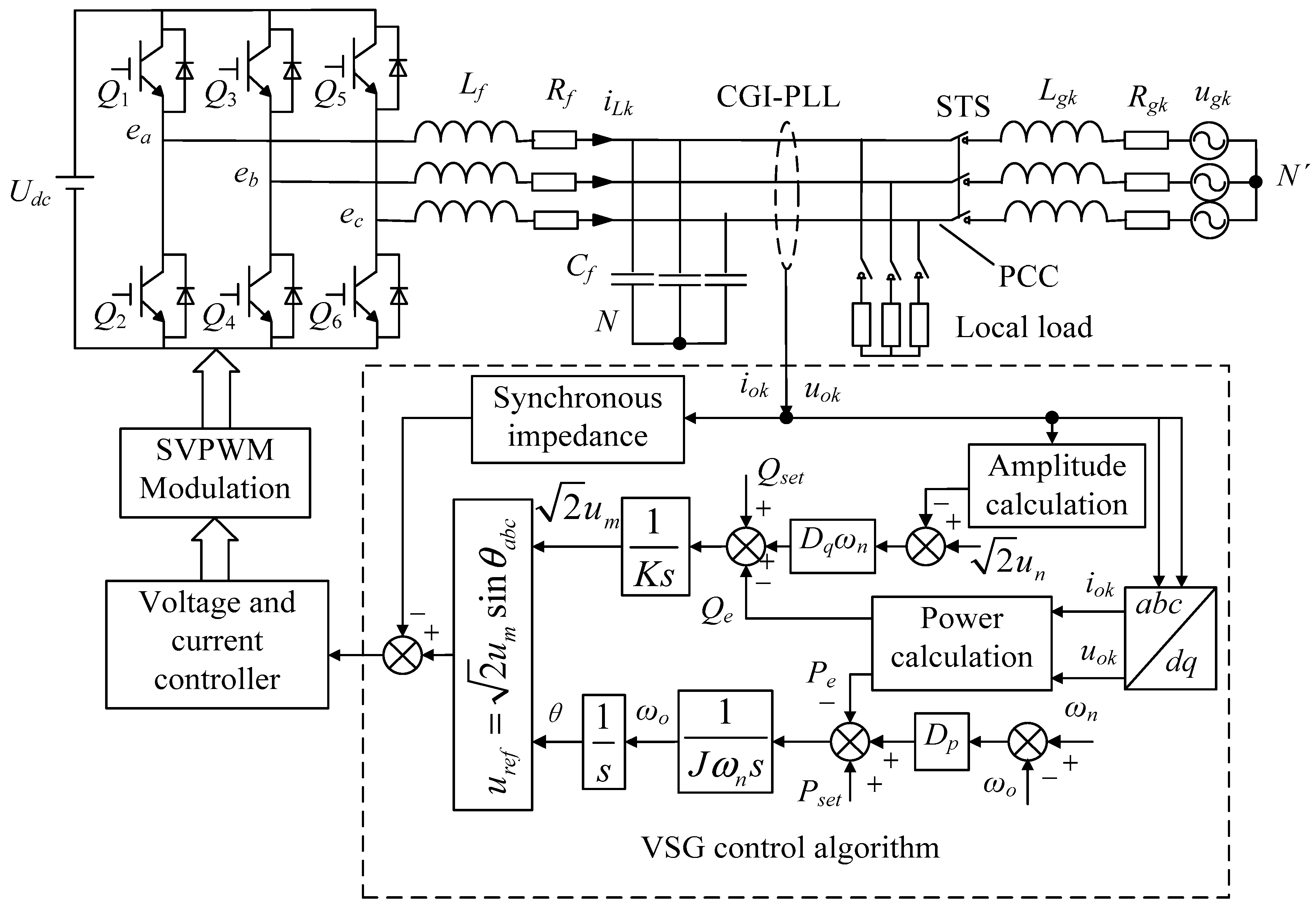
2. Structure and Control Strategy of Micro-Grid System

The voltage source micro-grid system based on VSG is mainly composed of static transfer switch (STS), micro-grid inverter based on VSG and electrical load. The main circuit structure of the voltage source inverter is a typical three-phase full-bridge inverter, as shown in Figure 1.
According to Refs. [5,6,7,8], the mathematical equations of the VSG control algorithm are as follows:
{ J d Δ ω d t = T s e t T e D p Δ ω d θ d t = ω
{ P s e t = T s e t ω T s e t ω n P e = T e ω T e ω n
{ P s e t + D p Δ ω P e J ω n d ω d t Q s e t + 2 D q Δ u Q e = K d 2 u m d t
where Δω = ωnω and Δu = unuo.
The instantaneous active power Pe and reactive power Qe can be calculated from the output voltage uok and the output current iok, that is:
{ P e = 3 2 ( u o d i o d + u o q i o q ) Q e = 3 2 ( u o q i o d u o d i o q )

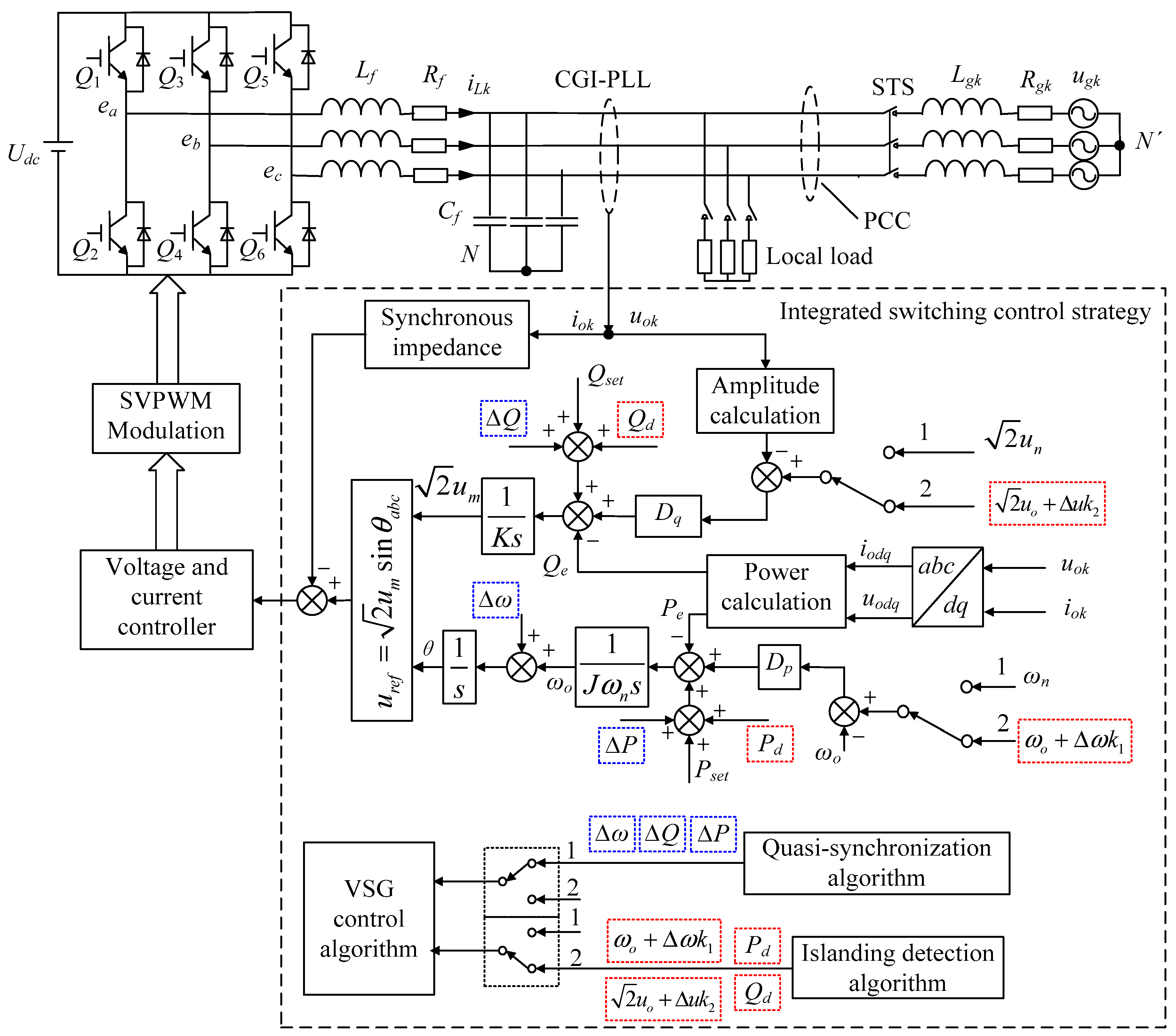
3. Integrated Control Strategy of Micro-Grid Systems

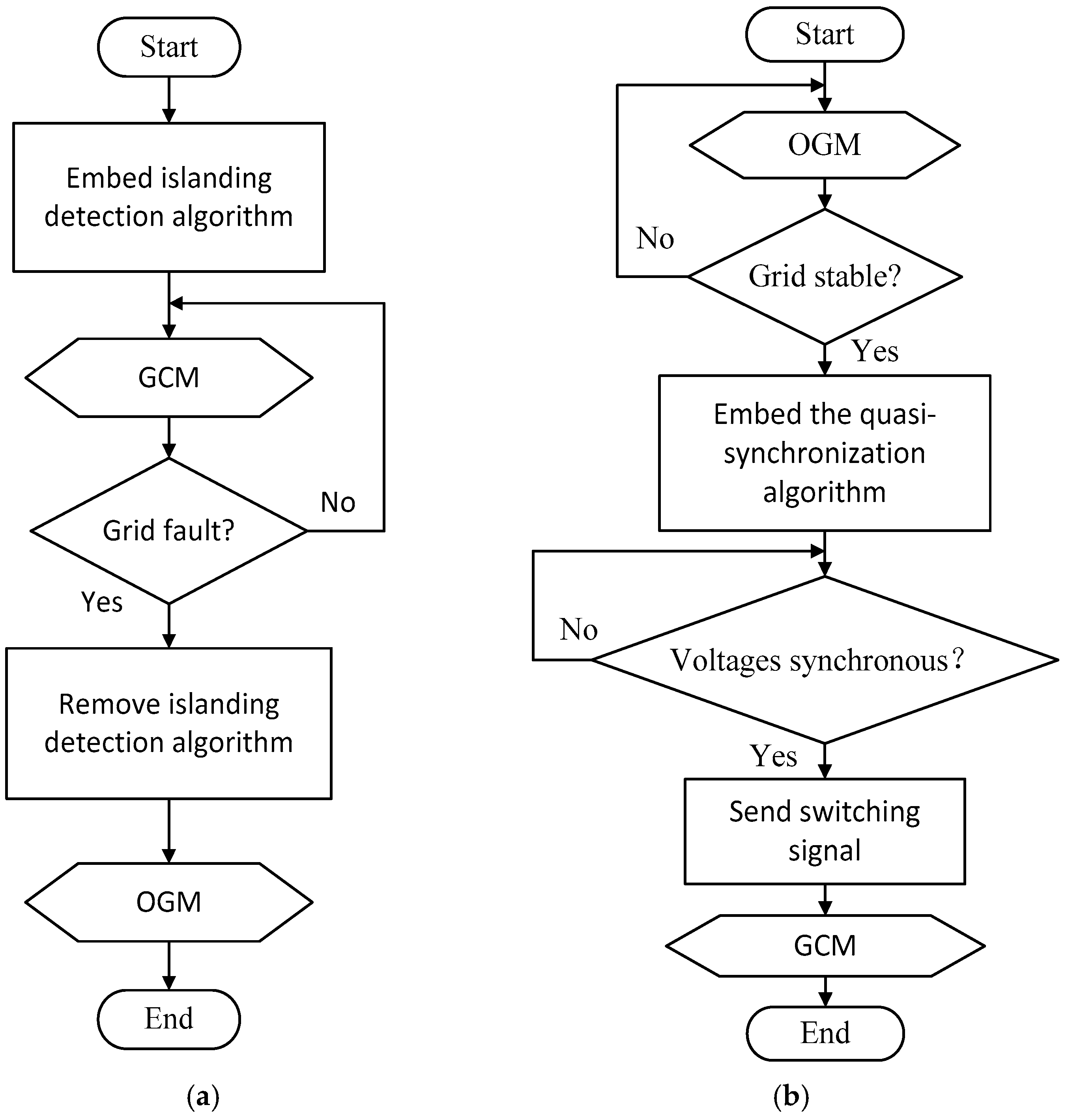
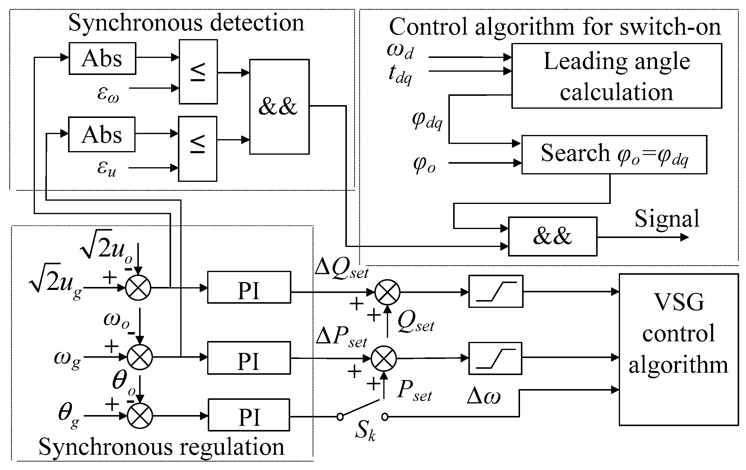
3.1. Smooth Switching Strategy of Micro-Grid Operation Modes

In order to realize the smooth switching between GCM and OGM in a micro-grid, an integrated switching control strategy of voltage-controlled type micro-grid inverter based on VSG technology is presented in Figure 2, and the control process in two cases is analyzed as follows:
Case I: When the micro-grid system switches to GCM, the corresponding control flowchart is shown in Figure 2a. The islanding detection algorithm is embedded in the VSG algorithm, which detected the islanding phenomenon all the time. If the grid is stable, the micro-grid still operates in GCM, while if the grid faults, the islanding detection algorithm detects the islanding phenomenon, then the controller sends switching signals to switch the inverter into OGM. Simultaneously, the islanding detection algorithm is cut out from the integrated switching control algorithm. At this point, the situation turn to case II and the control flowchart of the micro-grid is shown in Figure 2b.
Case II: The control flowchart when the micro-grid system switches to GCM is shown in Figure 2b. In order to achieve the automatic grid-connected operation when the grid is recovered, the grid should be checked at a fixed frequency. If the grid has not been recovered, the micro-grid will continue to work in OGM. When the grid fault is recovered, the quasi-synchronization algorithm would be embedded into the VSG control algorithm. Then, the micro-grid can be smoothly connected to the large grid. After realizing safe and reliable grid-connected operation, the islanding detection algorithm is re-embedded into the control algorithm. At this point, the situation turns to case I and the control flowchart of the micro-grid is shown in Figure 2a.
In summary, the integrated switching control strategy in detail is shown in Figure 3. The quasi-synchronization algorithm and islanding detection algorithm is described respectively in Section 3.3 and Section 3.4.

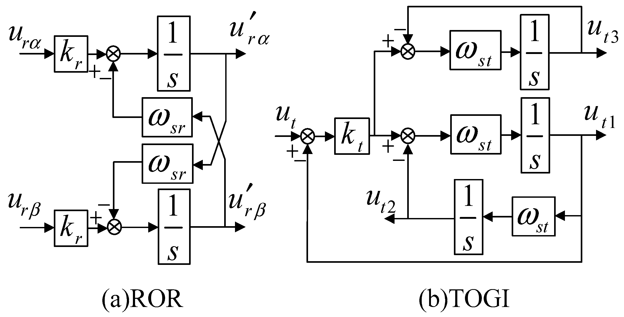
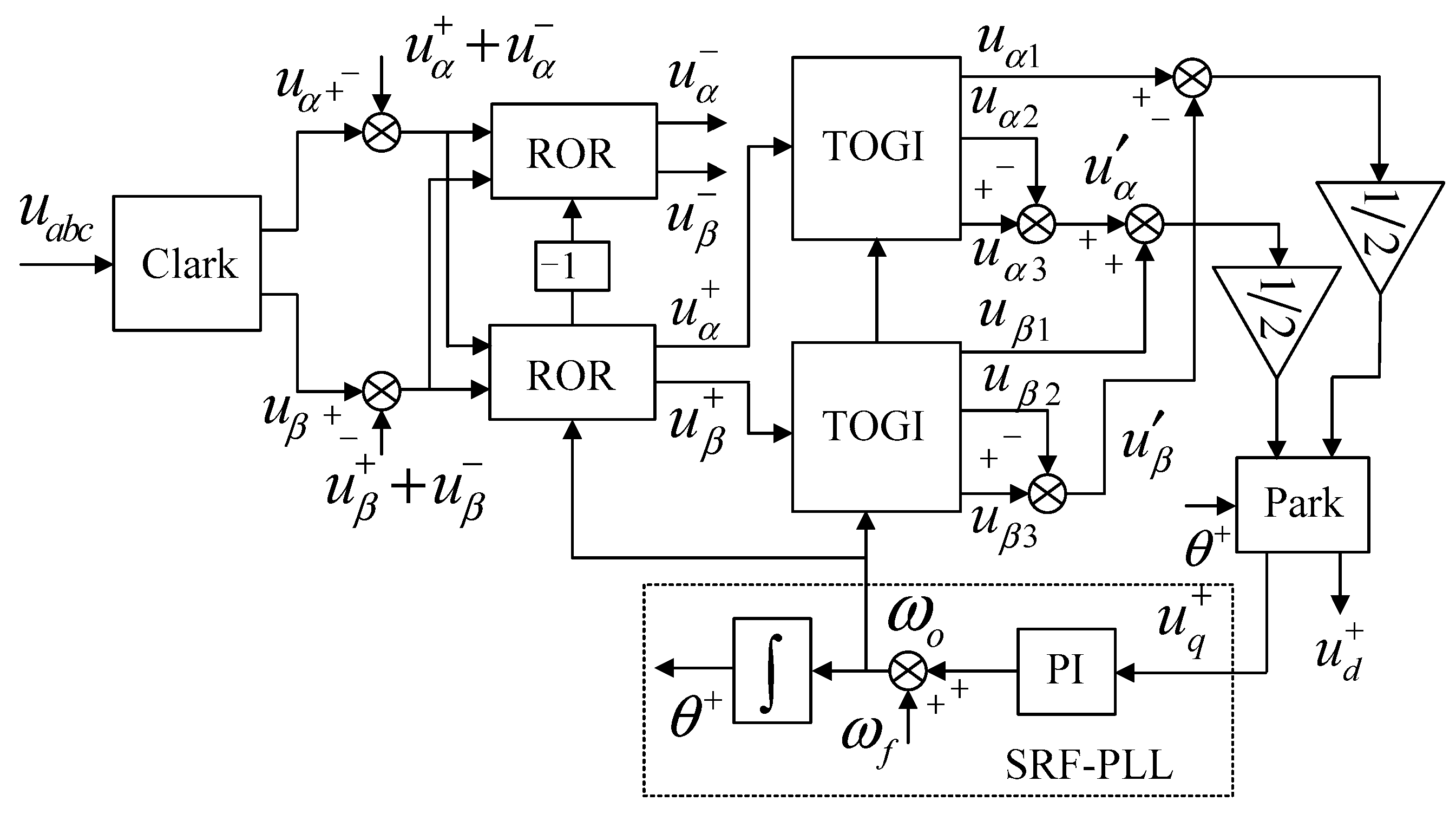
3.2. PLL Based on Cascaded General-Integrator

A PLL based on cascaded general-integrator (CGI-PLL), using a third-order general-integrator (TOGI) to suppress the influence of the DC component of the voltage on the system, is designed in this paper, as shown in Figure 1. However, TOGI has no ideal filtering effect on the lower harmonics of the voltage (such as 5th and 7th harmonics). The reduced order resonant (ROR) regulator can quickly and accurately achieve positive and negative sequence separation and harmonic separation by suppressing the influence of low-order harmonics. Thus, ROR regulator is used to make up for the disadvantages of TOGI in this paper.
The control block diagram of ROR regulator and TOGI can be seen in Figure 4. According to Refs. [20,21,22], the closed-loop transfer functions of ROR regulator and TOGI can be listed separately:
H α β = u r α β u r α β = k r s j ω s r
{ H 1 ( s ) = u t 1 ( s ) u t ( s ) = k t ω s t s s 2 + k t ω s t s + ω s t 2 H 2 ( s ) = u t 2 ( s ) u t ( s ) = k t ω s 2 s 2 + k t ω s t s + ω s t 2 H 3 ( s ) = u t 3 ( s ) u t ( s ) = k t ω s t ( s 2 + ω s t 2 ) ( s + ω s t ) ( s 2 + k t ω s t s + ω s t 2 )
The asymmetrical grid voltage with harmonic is transformed into αβ stationary coordinate system, that is:
u α β = u α β + + u α β + m = 1 u α β n
{ u α β + = [ u α + u β + ] = U + [ cos ( ω o t + φ + ) sin ( ω o t + φ + ) ] u α β = [ u α u β ] = U [ cos ( ω o t + φ ) sin ( ω o t + φ ) ] u α β n = [ u α n u β n ] = U + [ cos ( n ω o t + φ n ) sin ( n ω o t + φ n ) ]
From (5), the ROR regulator has only one pole, s = sr, with frequency and polarity selectivity. Therefore, ROR can directly perform positive, negative and harmonic separation by setting the resonant frequency.
According to Ref. [23], the voltage containing the DC offset component is expressed as:
u ( t ) = u o + u m sin ( ω s t t + φ s )
The resonant frequency of TOGI is equal to the fundamental frequency of the voltage, ωst = ωo. Therefore, the TOGI output signals can be expressed as:
{ u 1 = u m sin ( ω o t + φ o ) u 2 = K s u o u m sin ( ω o t + φ o ) u 3 = K s u o
From (6), H1(s) can be seen as a band-pass filter whose bandwidth is determined by kt, H2(s) can be seen as a low-pass filter, H3(s) can be seen as a notch filter with notch frequency ωst. Therefore, when the input voltage contains DC component, ut1(t) is a output voltage without DC component and with the same frequency as the AC component of the input voltage, ut2(t) is a output voltage with DC component and the same amplitude as the input voltage, but the phase of ut2(t) lag the input voltage by 90°, ut3(t) only contains DC component. Thus, TOGI can generate two-phase quadrature signal with the same frequency and same amplitude as the fundamental wave component of the input voltage.
The structure of CGI-PLL, as shown in Figure 5, is composed of ROR regulators, TOGIs, and SRF-PLL. For one thing, the ROR regulators decouple the voltage positive and negative sequence and remove the harmonics; for another, the TOGIs suppress the DC component and perform secondary separation and filtering; and then, the SRF-PLL realizes the phase angle and frequency tracking, where ωo of the TOGI and ROR regulators is obtained from the SRF-PLL. The performance of CGI-PLL in complex voltage conditions is shown in Figure 6.

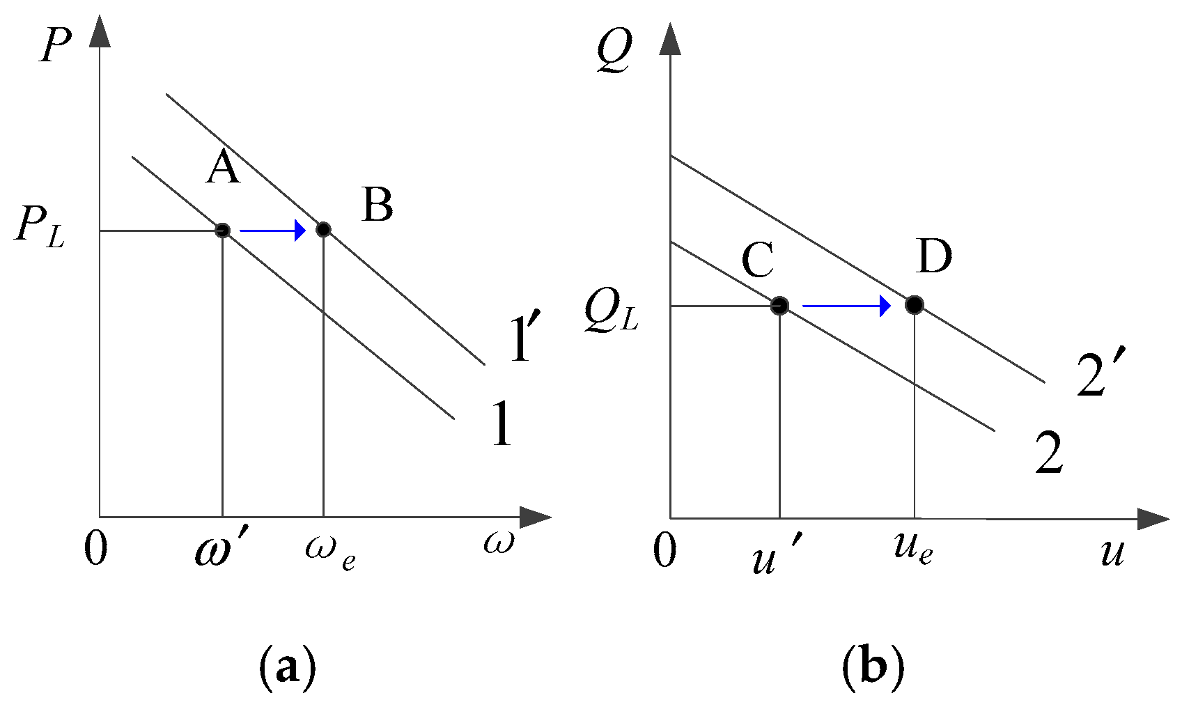
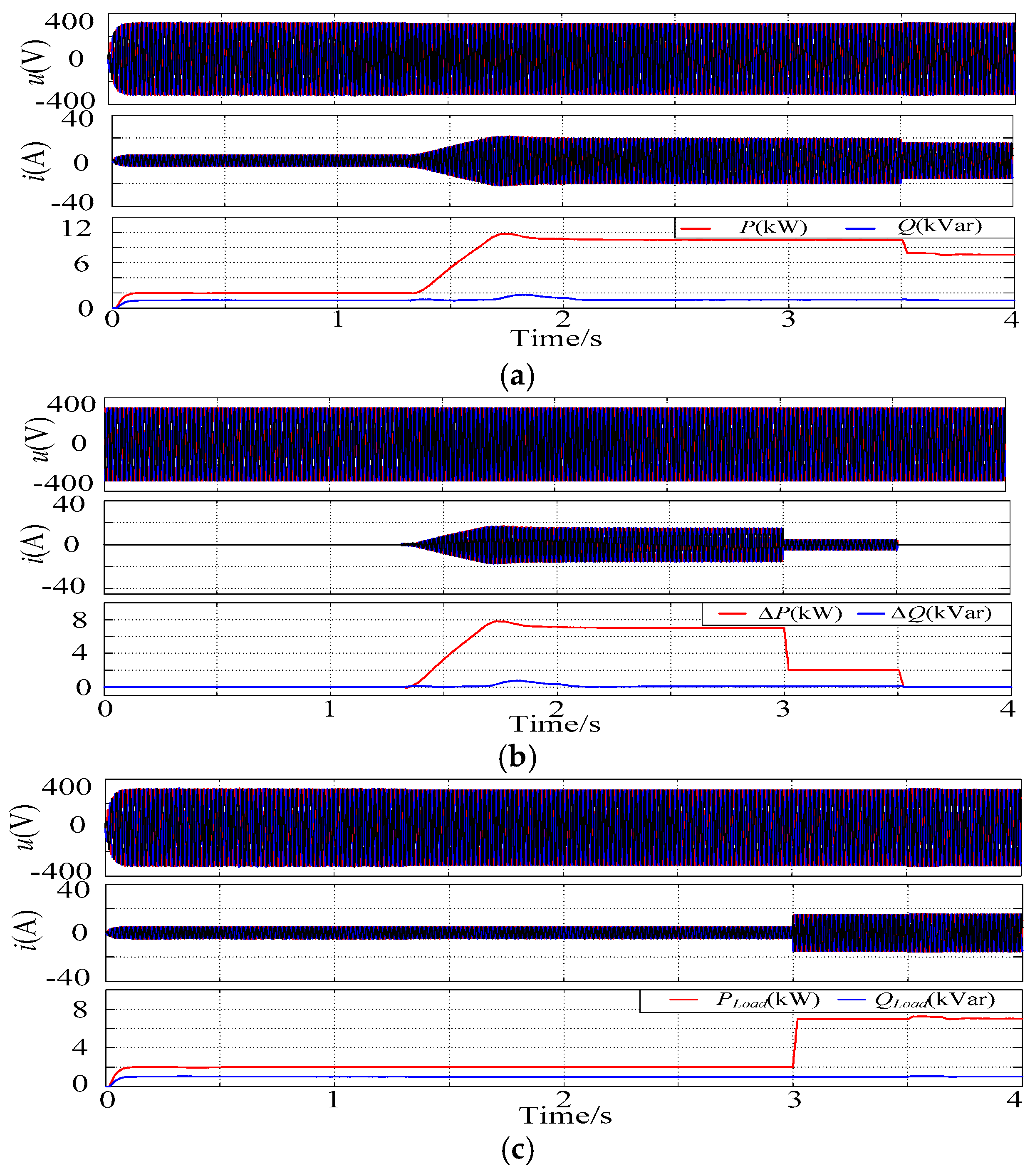
3.3. Active Switching Control from OGM to GCM

The micro-grid inverter based on VSG has two modules of power reference and droop control. During GCM, the inverter operates according to the given power Pset and Qset, while during OGM, the inverter operates according to the droop characteristics of P-f and Q-V. When the frequency or voltage of the system deviates too much from the reference value, the system can perform secondary adjustment of the frequency or voltage, which is secondary frequency regulation or secondary voltage regulation. Therefore, the micro-grid can actively adjust the voltage and frequency during OGM, which is exactly the theoretical basis for the micro-grid switching from OGM to GCM. The micro-grid inverter realizes secondary voltage and frequency regulation by controlling Pset and Qset in the droop characteristic curve, as shown in Figure 7.
Taking secondary frequency regulation as an example, the Pf curve of the inverter is shifted from 1 to 1′ by adjusting the given active power from Pset to Pset. Suppose the system active load PL is constant, and the micro-grid system will run at point B whose frequency is ωe. According to Refs. [24,25], the new Pf curve 1′ is:
{ P G = P s e t + ( ω n ω ) ω n D p P s e t = P s e t + Δ P s e t
where ∆Pset is:
Δ P s e t = ( k ω p + k ω i s ) ( ω g ω o )
Similar to a prime mover, the given active power Pset should be limited [26], and the new QV curve can be obtained as:
{ Q G = Q s e t + ( u n u ) D q Q s e t = Q s e t + Δ Q s e t
where ∆Qset is:
Δ Q s e t = ( k u p + k u i s ) ( u g u o )
The quasi-synchronization grid-connected algorithm is composed of a synchronous detection unit, a synchronous regulation unit and a closing unit, which is shown in Figure 8.
In this paper, the allowable voltage difference is εu = 5%ug and the allowable frequency difference is εω = 0.4%ωg. Otherwise, the synchronous adjustment unit will perform secondary voltage and frequency regulation by increasing (or decreasing) ∆Qset, ∆Pset.
The phase angle difference, ∆θ, has the greatest impact on the inverter when connected to the grid. Therefore, a phase angle regulator is added to indirectly adjust the phase angle difference by directly adjusting the frequency of the micro-grid to realize ∆θ ≈ 0. When the frequency difference between the micro-grid system and the grid is less than εω, the phase angle regulator will run, that is:
S k = { 1 ; | ω g ω o | < ε ω 0 ; | ω g ω o | ε ω
Considering the intrinsic actuation time of controller and circuit breaker, the switching signal should be sent in advance. The incremental angle is usually called leading angle, which can be expressed as (16):
φ d q = ω d t d q + 1 2 × d ω d d t t 2 d q + 1 6 × d 2 ω d d t 2 t 3 d q
where ωd = εω.

3.4. Reactive Switching Control between OGM and GCM

In order to reduce the impact of unplanned switching processes on the micro-grid system, the micro-grid system must be able to effectively detect the occurrence of islanding phenomenon. According to IEEE Std.1547 [27], when unplanned islanding occurs, the islanding state needs to be detected by the control system within 2 s. The frequency thresholds are typically set at 49.3 Hz and 50.5 Hz, and the voltage thresholds are set at 193.6 V and 242 V.
The power flow at the point of common coupling (PCC) point in Figure 1 satisfies the Power Conservation principle, that is:
{ P L o a d = P + Δ P Q L o a d = Q + Δ Q
The frequency and voltage deviation caused by the unmatched power can be described as follows:
{ ω o ( k ) = ω n ( k ) Δ P / D p 2 u o ( k ) = 2 u n ( k ) Δ Q / D q
According to (18), it is obvious that there is a certain mathematical relationship between the change of frequency and voltage and the variation of active power and reactive power. Therefore, the islanding phenomenon can be detected through frequency or voltage amplitude changes. If the frequency of the system deviates from the normal frequency by more than 2 Hz or the voltage exceeds 20% of the rated voltage, the micro-grid operation should be switched to OGM immediately.
In order to solve the problem of large NDZ in the detection method, positive feedback of VQ is added on the basis of [19] in this paper. When unplanned islanding occurs, the frequency and voltage of inverter will shift to a certain direction under the influence of droop characteristics and positive feedback. During OGM, the inverter sets the reference frequency and voltage to fixed values. The specific control schematic diagram is shown in Figure 9.
According to Figure 8, the output voltage and frequency of the inverter can be expressed by (19) and (20):
{ ω o ( k ) = Δ ω k 1 + ω o ( k ) Δ P D p 2 u o ( k ) = 2 Δ u k 2 + 2 u o ( k ) Δ Q D q
{ Δ ω = ω o ( k 1 ) ω o ( k ) Δ u = u o ( k 1 ) u o ( k ) Δ P = P L o a d ( P + P d ) Δ Q = Q L o a d ( Q + Q d )
Based on (19) and (20), it can be seen that when ki > 1 (i = 1, 2), the positive feedback effect can be enhanced. However, it should be noted that, if ki is too large, islanding phenomenon would occur due to the large fluctuations, while if ki is too small, the offset value of voltage or frequency would exceed the detection thresholds for a long time. Therefore, the value of ki need be discussed in this paper.
Case I: When uo ≤ 0.88un or uo ≥ 1.1un, or fo ≤ 49.3 Hz or fo ≥ 50.5 Hz, the occurrence of islanding phenomenon can be detected directly. At this time, it is not necessary to add positive feedback, that is, ki = 1.
Case II: When the grid is disconnected, the inverter output power and the power required by the loads are completely matched or the degree of mismatch is small. At this time, the range of voltage amplitude is 0.88unuo ≤ 1.1un, or the range of frequency is 49.3 Hz ≤ fo ≤ 50.5 Hz. The voltage or frequency of the inverter does not change or change slightly. Therefore, the islanding phenomenon cannot be quickly and effectively detected. In this situation, positive feedback is required to accelerate the detection speed. To avoid false islanding, it can be considered that islanding phenomenon is highly likely to occur only when the voltage amplitude or frequency changes several times in the same direction. In this situation, it is necessary to add positive feedback to accelerate the detection speed and reduce NDZ.
In summary, the value of ki is chosen as:
k i = { 1 ; { u o 0.88 u n ,   u o 1.1 u n f o 49.3 H z ,   f o 50.5 H z N < 10 5 ; { 0.88 u n u o 1.1 u n 49.3 H z f o 50.5 H z N 10
If the amplitude or frequency change once in the same direction, N will automatically increase by one. If the amplitude or frequency of the previous two amplitudes changes in different directions, N is set to 0.
In order to further reduce the NDZ and accelerate the detection speed, power disturbance basing on of positive feedback is presented in this paper. As shown in Figure 8, Pd, Qd represent positive and reactive power disturbances, respectively. Simultaneously, for the purpose of avoiding the impact of power disturbance on the normal operation of the inverter, whether to start the power disturbance is determined by judging the ki value. When ki > 1, active or reactive power disturbance should be added to the given power of the inverter according to the k1 and k2 values. With the aim of reducing the power disturbance value, the addition of positive or negative disturbance is determined based on the ∆u and ∆ω values. When ∆u and ∆ω is positive, negative power disturbance is added, otherwise positive power disturbance is added. The introduction of power disturbances essentially increases the difference of power, which can reduce the NDZ. The flowchart of the islanding detection is shown in Figure 10.

4. Controller Behavior and Simulation Results

The simulation model of the micro-grid system based on VSG with integrated switching control strategy is established in Matlab/Simulink. The specific simulation parameters are listed in Table 1, and the comprehensive simulation results are given in the following.

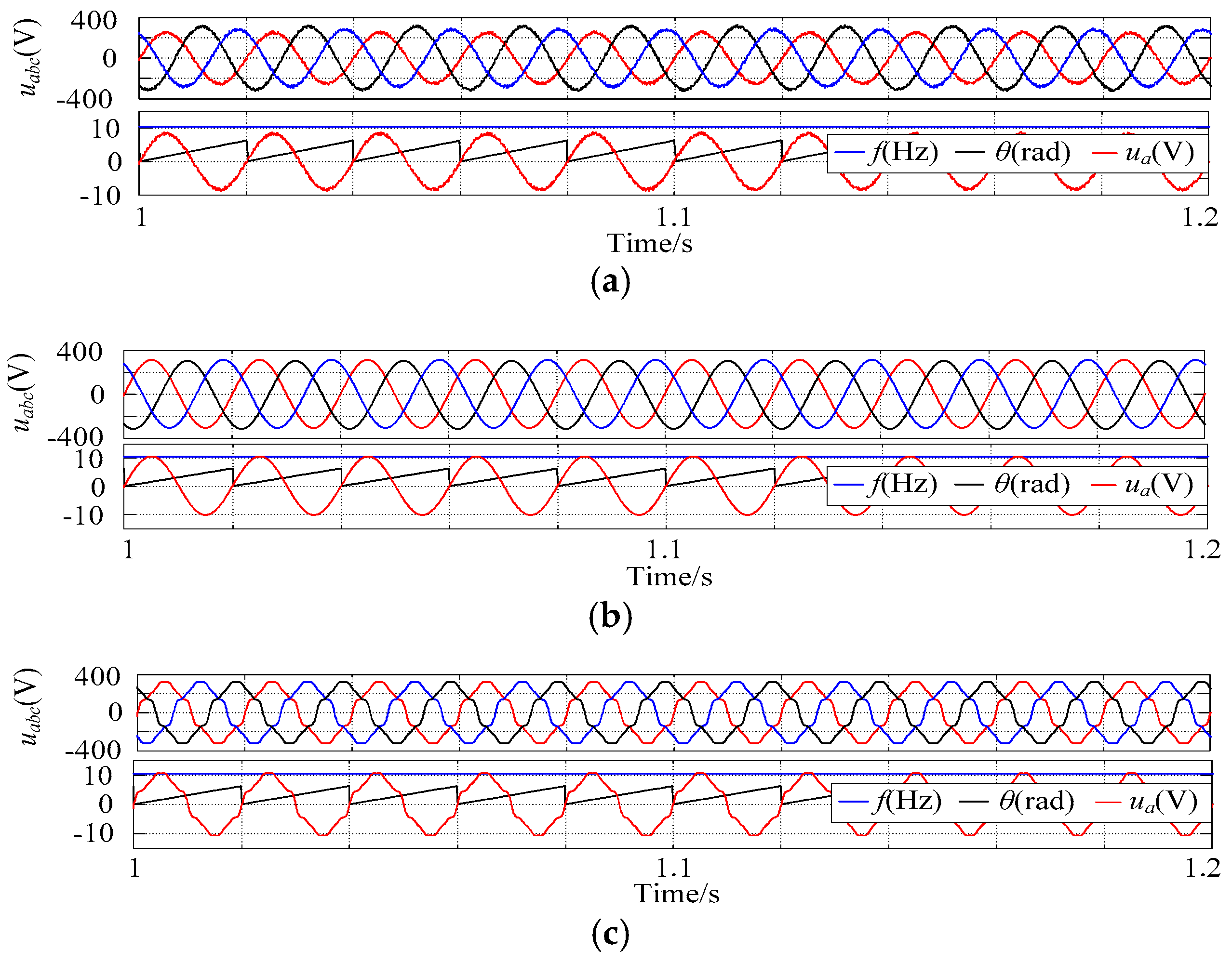
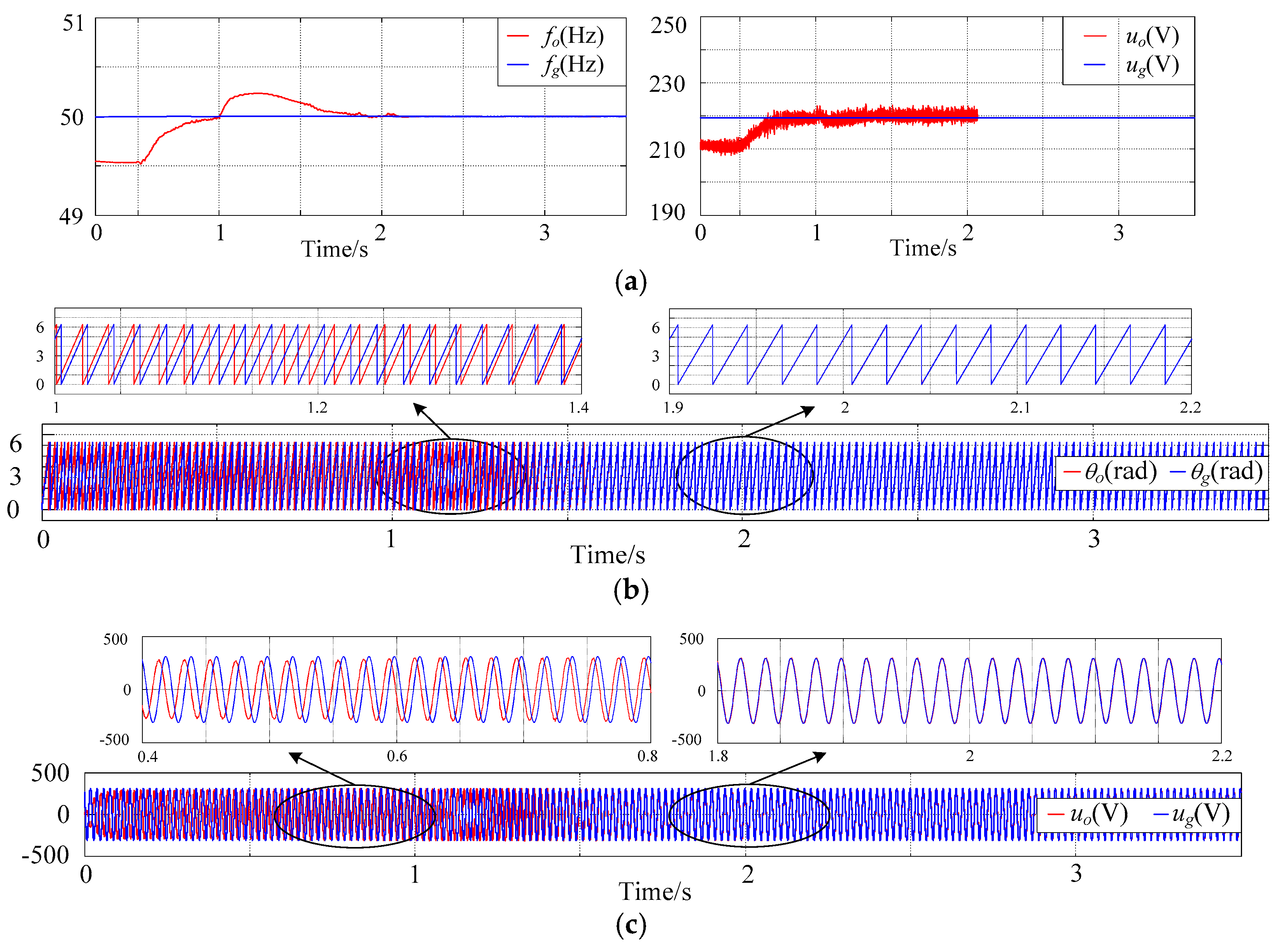
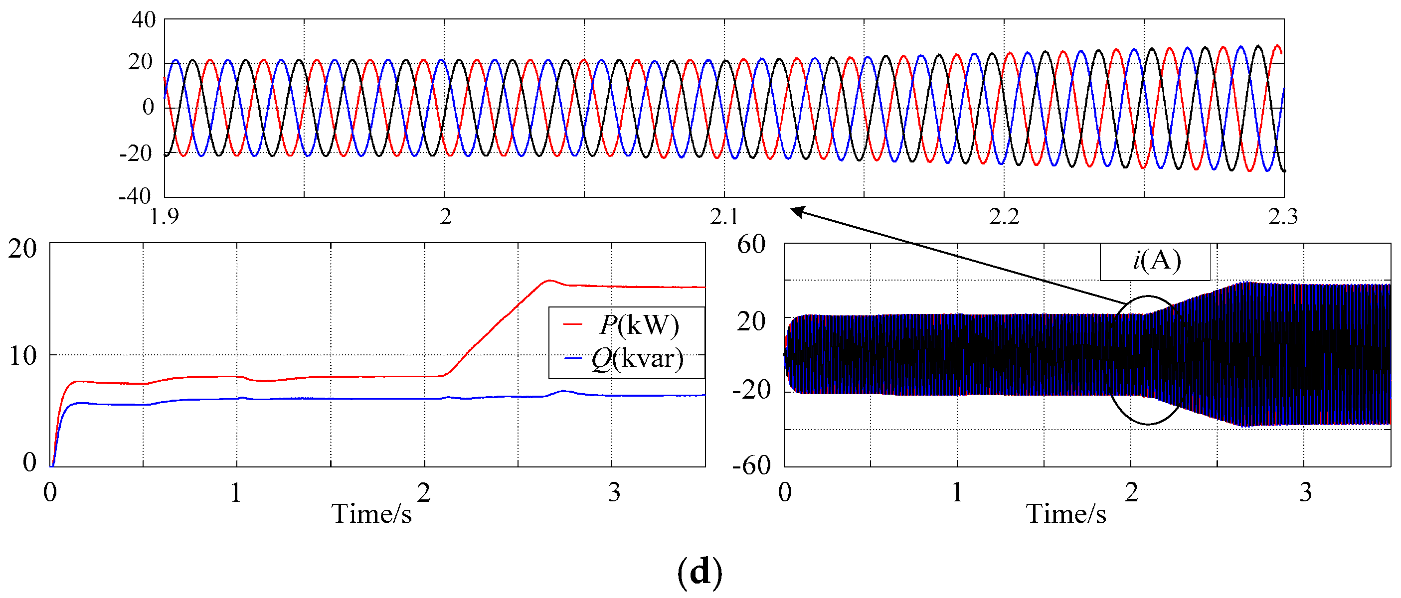
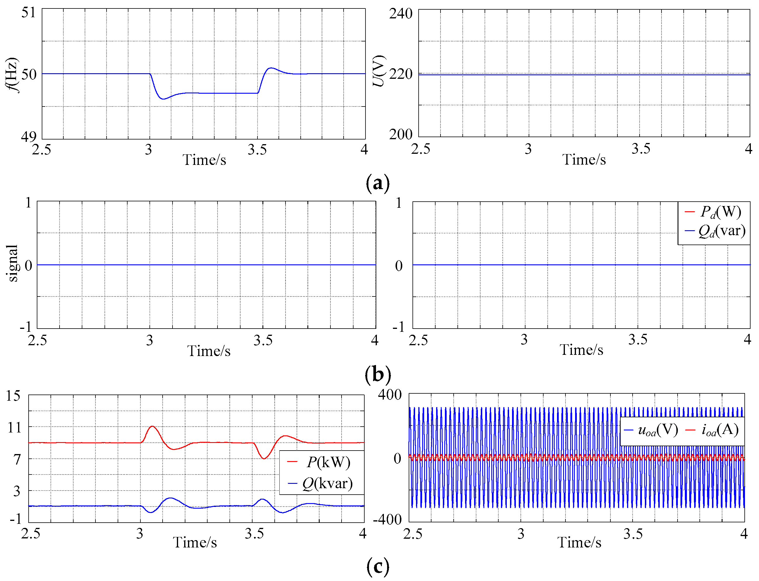
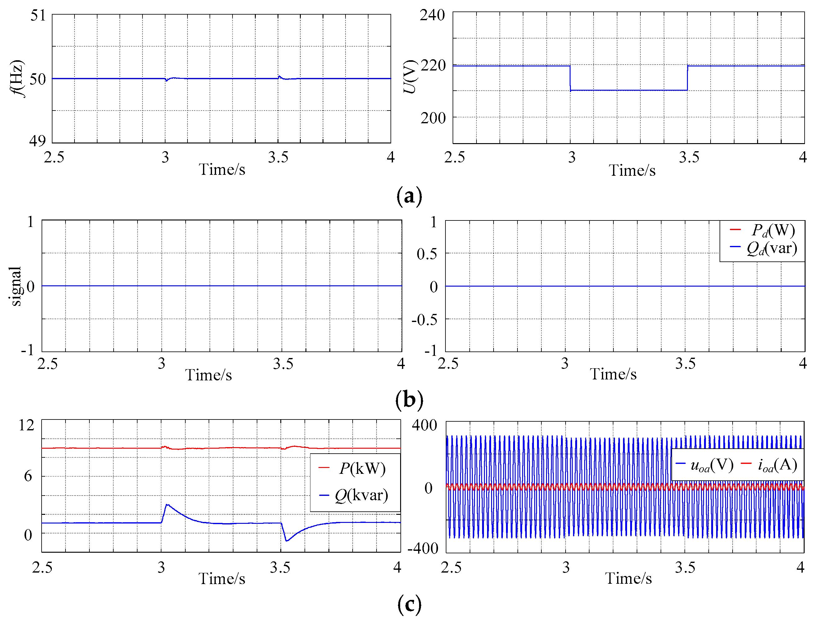
4.1. Quasi-Synchronization Process from OGM to GCM

Aiming at verifying the proposed VSG control algorithm, a quasi-synchronization algorithm is adopted to realize the smooth switching from OGM to GCM and the stability maintainence of voltage and frequency as well.
In the micro-grid, PLoad, QLoad are 8 kW and 6 kVar respectively, while the initial values of Pset and Qset are 3 kW and 1 kVar respectively. The amplitude of voltage at the PCC is 211 V and the frequency is 49.5 Hz, and the grid is ideal. At 0.5 s, the controller sends a signal to incorporate the CGI-PLL and the quasi-synchronization algorithm into the VSG control algorithm. The value of Pset gradually increases to 16 kW, and the value of Qset gradually increases to 6 kVar. The simulation results of quasi-synchronization process are shown in Figure 11.
As shown in Figure 11, under the effect of the quasi-synchronization algorithm, the micro-grid inverter controls the voltage amplitude and frequency according to active and reactive power commands after 0.5 s. Therefore, the micro-grid voltage is gradually synchronized with the grid voltage. At 2.06 s, the micro-grid voltage meets the grid-connection standards and the micro-grid operates on GCM, the synchronization process is completed. From the Figure 10d, there is no large current fluctuations at the grid-connected moment, and the grid-connected process is smooth. Then, the micro-grid system begins to supply power to the grid. After about 2.7 s, the micro-grid is stable. And the micro-grid not only supplies 8 kW and 6 kVar power to the load, but also supplies extra 8 kW power to the grid.

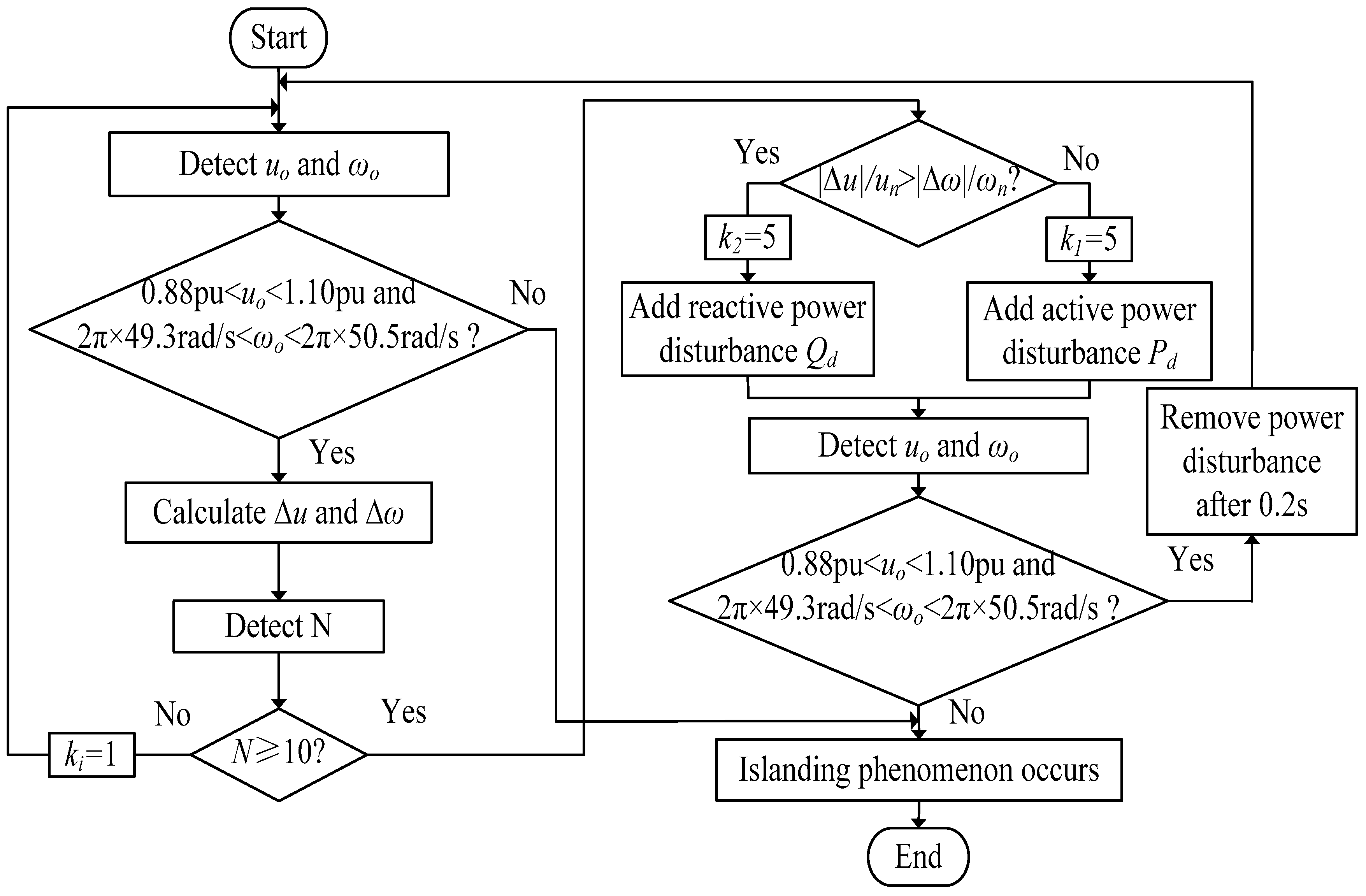
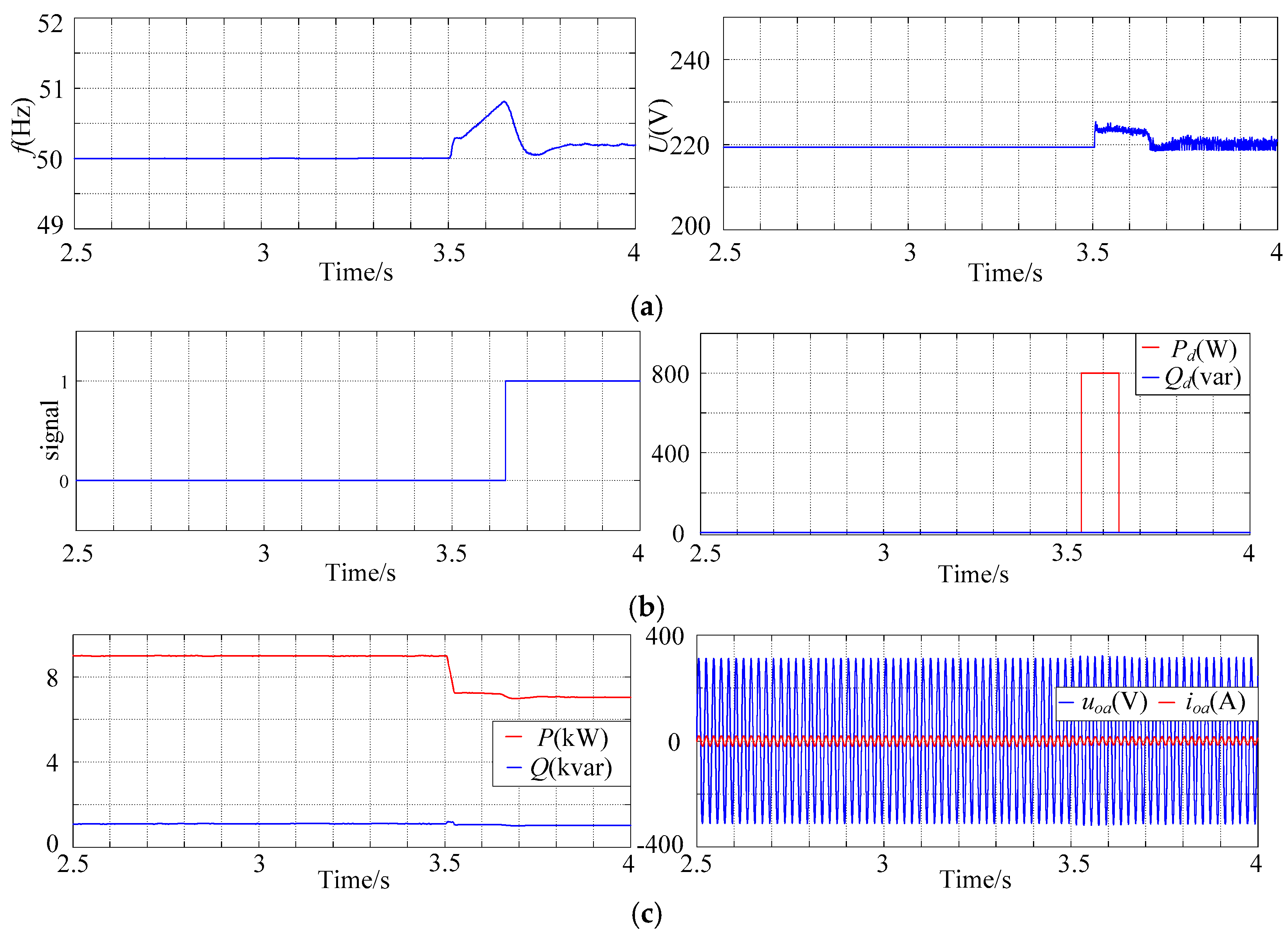
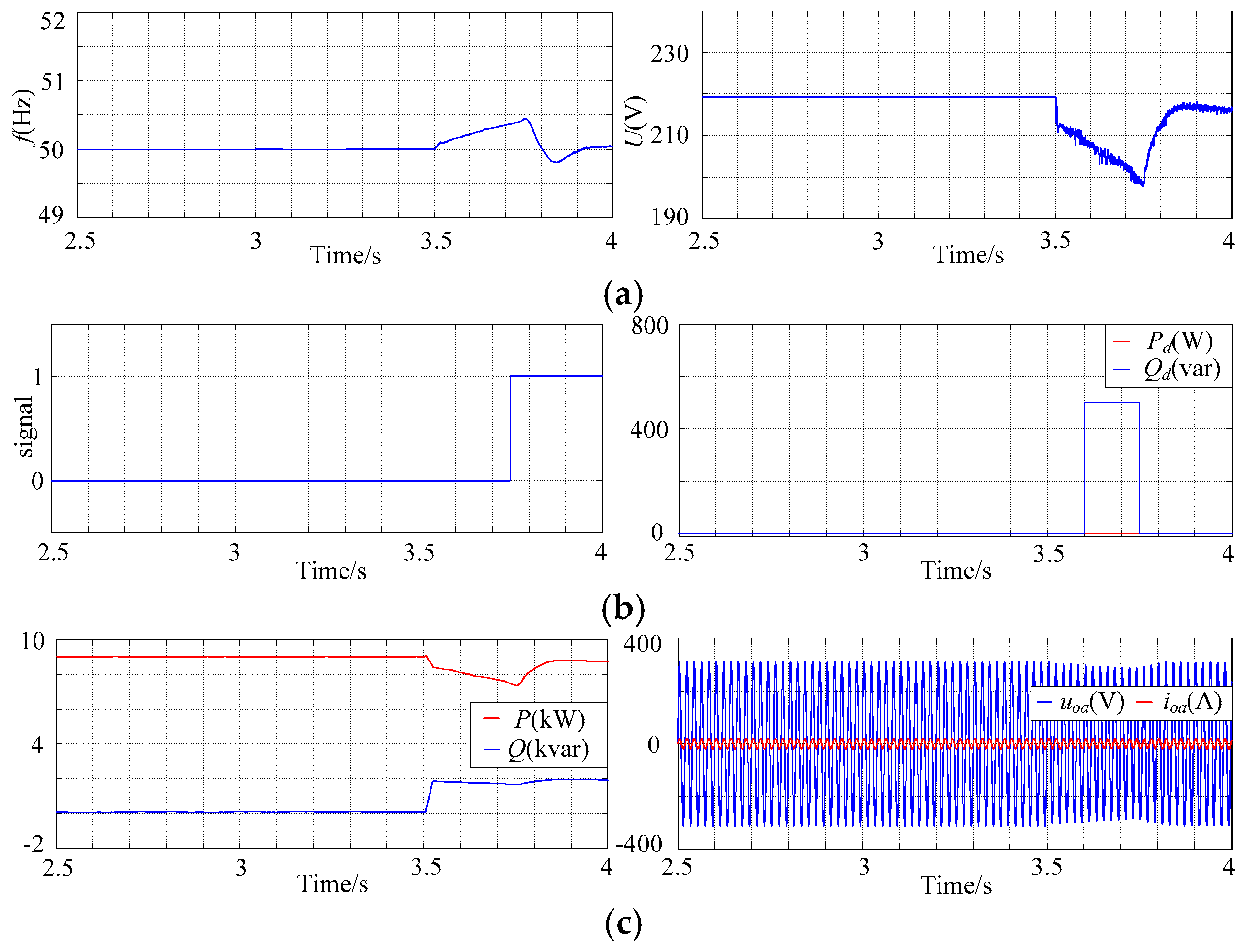
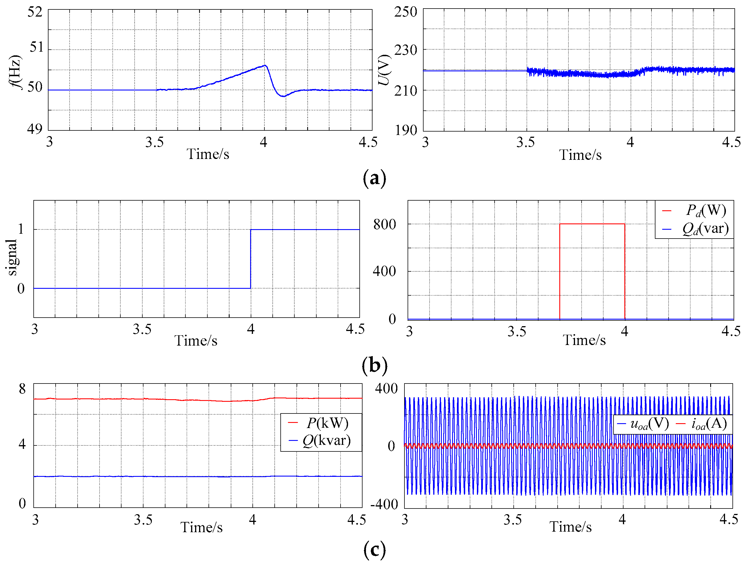
4.2. Switching Control from GCM to OGM

In order to verify that the proposed islanding detection algorithm can effectively detect the islanding phenomenon and smoothly switch from GCM to OGM, the simulation experiments on micro-grid model are as follows:
Case I: PLoad, QLoad are 2 kW and 1 kVar, respectively, and Pset, Qset of the VSG control algorithm are 9 kW and 1 kVar, respectively. The micro-grid is connected to the grid at 1.3 s. After the connection, the islanding detection algorithm is embedded into integrated control strategy. At 3.0 s, 5 kW load is connected to the migro-grid system, and the grid is disconnected at 3.5 s. The simulation ends at 4.0 s, and the simulation results are shown in Figure 12.
Case II: PLoad, QLoad are 2 kW and 0 kVar, respectively, and Pset, Qset are 9 kW and 0 kVar, respectively. With other simulation parameters unchanged, the load of 7 kW and 2 kVar is connected to the micro-grid system at 3.0 s to simulate the reactive power of the micro-grid unmatched with the load power. The simulation results are shown in Figure 13.
Case III: PLoad, QLoad are 2 kW and 1 kVar, respectively. Pset, Qset are 7 kW and 2 kVar, respectively. With other simulation parameters unchanged, the load of 5 kW and 1 kVar is connected to the micro-grid system at 3.0 s, when the output power of the micro-grid completely matches with the load power. The simulation results are shown in Figure 14.
Based on Figure 12, when the active power is unmatched, the frequency will rise (or fall) under the effect of P-f droop characteristics. When the frequency deviation exceeds normal level, the positive frequency feedback and active power disturbance starts, which makes the frequency of the output voltage exceeds normal range rapidly. Thus the islanding phenomenon is detected. The entire time of islanding detection lasts about 0.12 s. As shown in Figure 13, the frequency will fluctuate with the reactive power unmatched. And the fluctuation of frequency is smaller than that of voltage amplitude. Consequently, when the amplitude deviation exceeds normal level, the positive voltage feedback and reactive power disturbance starts, which makes the amplitude of the output voltage rapidly exceeds normal range. Thus the islanding phenomenon is detected. The entire time of islanding detection lasts about 0.22 s. According to Figure 14, the micro-grid is disconnected from the grid at 3.5 s. During 3.5 s to 3.7 s, the frequency changes slightly because the output power of the inverter is matched with the power of the loads. At 3.7 s, positive feedback and active power disturbance are added, which accelerates the change of frequency. The entire time of detection process lasts about 0.5 s. Once the islanding phenomenon is detected, the PCC quickly switches the micro-grid to operate at OGM. Moreover, the detection time is less than 2 s, which meets the standard of islanding detection.
Case IV: The micro-grid system is connected to the grid all time. At 3.0 s, the frequency and amplitude of the grid voltage drop 0.3 Hz and 10 V respectively, and the condition of false islanding is simulated. The disturbance time lasts 0.5 s. The other simulation parameters are the same as case I. The simulation results are shown in Figure 15 and Figure 16.
From Figure 15 and Figure 16, it can be found that when false islanding occurs, the amplitude and frequency of the voltage at the PCC fluctuates with the grid voltage. However, the positive feedback and power disturbance does not start, and the signal of islanding detection shows that islanding phenomenon do not occur. It can be concluded that false islanding can be effectively identified using novel islanding detection algorithm.
Case V: Taking case I as an example, the switching process of the micro-grid inverter between GCM and OGM is analyzed, and the simulation results are shown in Figure 17.
According to Figure 17, the micro-grid inverter based on VSG control can provide essential power supply for the load with no supply from the grid. When the micro-grid is connected to the grid, the switching process is smooth due to the proposed control algorithm. When some other loads are connected to the micro-grid system, there is no large voltage or current fluctuations. When unplanned islanding occurs, the islanding phenomenon can be detected immediately and the micro-grid operation can actively be switched to OGM. Therefore, under the effect of the integrated swithching control strategy proposed in this paper, the micro-grid system can operate reliably and stably.

5. Conclusions

In this paper, an integrated swithching control strategy based on the VSG algorithm was adopted for voltage-controlled type micro-grid inverter. The integrated switching control strategy combines the VSG algorithm with the CGI-PLL, a quasi-synchronization algorithm and a novel islanding detection algorithm, whereby the risk of switching failure can be effectively reduced and the transient response during the switching process can be strongly suppressed. Compared with traditional PLL technology, the CGI-PLL presented in this paper can accurately obtain the information of voltage when the voltage is asymmetric and distorted. The quasi-synchronization algorithm can suppress the impact current at grid-connected moment. The switching process from OGM to GCM for micro-grid system adopted quasi-synchronization algorithm is smoother than the micro-grid system without it. Compared with traditional islanding detection methods, the novel islanding detection method can detect islanding phenomenon effectively, reduce the non-detection zone and cut into the islanding operation. Theoretical analysis and simulation results verify the rationality and validity of this integrated switching control strategy.

Author Contributions

Conceptualization, K.S. and G.Z.; Data curation, H.Y.; Formal analysis, G.Z. and F.T.; Investigation, G.Z., P.X., H.Y. and F.T.; Methodology, K.S., G.Z., P.X. and H.Y.; Project administration, G.Z.; Supervision, K.S., G.Z., P.X. and F.T.; Validation, G.Z.; Writing—original draft, G.Z.; Writing—review & editing, K.S., G.Z., P.X. and H.Y.

Funding

This research was funded by [National Natural Science Foundation of China] grant number [51407085], [Postdoctoral Science Foundation of China] grant number [2015M571685] and [Priority Academic Program Development of Jiangsu Higher Education Institution and Jiangsu University Senior Talents Special Project] grant number [13JDG111].

Acknowledgments

This work is supported by the National Natural Science Foundation of China (Grant No. 51407085), the Postdoctoral Science Foundation of China (2015M571685) and the Priority Academic Program Development of Jiangsu Higher Education Institution and Jiangsu University Senior Talents Special Project (13JDG111).

Conflicts of Interest

The authors declare no conflict of interest.

Nomenclature

QiIGBT device (i = 1–6)
Lfilter inductors
Cfilter capacitors
RLsum of equivalent resistances of the filter inductors, switching devices and circuits
iLkcurrent of the filter inductor (k = a, b, c)
iokoutput current of the inverter (k = a, b, c)
uokoutput voltage of the inverter (k = a, b, c)
Rgequivalent resistance of the grid
Lgequivalent inductance of the grid
ugkgrid voltage (k = a, b, c)
Tsetgiven torque
Teelectromagnetic torque
Psetgiven active power
Qsetgiven reactive power
θelectrical angle
Δωelectrical angle speed difference
ωnrated electrical angular velocity
ωactual electrical angular velocity
Δuoutput voltage difference
unrated voltage
uooutput voltage
umeffective value of voltage
Jinertia coefficient of active power loop
Kinertia coefficient of reactive power loop
Dpdroop coefficient of P-f
Dqdroop coefficient of Q-V
Peinstantaneous active power
Qeinstantaneous reactive power
uodqcomponents of uok in the dq rotating reference frame
iodqcomponents of iok in the dq rotating reference frame
u, uinput voltages of ROR
utinput voltage TOGI
ωsrresonant frequency of ROR
ωstresonant frequency of TOGI
krclosed-loop system gain of ROR
ktclosed-loop system gain of TOGI
urαβoutput voltages of ROR regulator
utkoutput voltages of TOGI regulator (k = 1, 2, 3)
ωdangular frequency difference
tdqlead time
PLoadactive power consumed by loads in normal operation
QLoadreactive power consumed by loads in normal operation
Pactive output power of the inverter
Qreactive output power of the inverter
Punmatched active power
Qunmatched reactive power
kifeedback proportion coefficients (i = 1, 2)
Pdactive power disturbance
Qdreactive power disturbance
ωo(k)VSG output angular frequency
ωn(k)rated angular frequency
2 u o ( k ) output values of the voltage
2 u n ( k ) reference values of the voltage
Ncounting value of the change of amplitude or frequency

References

  1. Shuai, Z.; Sun, Y.; Shen, Z.J.; Tian, W.; Tu, C.; Li, Y.; Yin, X. Micro-grid stability: Classification and a review. Renew. Sustain. Energy Rev. 2016, 58, 167–179. [Google Scholar] [CrossRef]
  2. Hatziargyriou, N.; Asano, H.; Iravani, R.; Marnay, C. Microgrids: An overview of ongoing research, development, and demonstration projects. IEEE Power Energy Mag. 2007, 5, 1045–1050. [Google Scholar] [CrossRef]
  3. Wang, C.; Li, X.; Guo, L.; Li, Y. A seamless operation mode transition control strategy for a microgrid based on master-slave control. In Proceedings of the 31st Chinese Control Conference, Hefei, China, 25–27 July 2012; Volume 55, pp. 1644–1654. [Google Scholar]
  4. Zhuo, F.; Yang, M.J.; Wang, X.W. Research of seamless transfer control strategy of microgrid system. In Proceedings of the IEEE International Conference on Power Electronics & Ecce Asia, Jeju, Korea, 30 May–3 June 2011; pp. 2059–2066. [Google Scholar]
  5. Zhong, Q.C.; Weiss, G. Synchronverters: Inverters that mimic synchronous generators. IEEE Trans. Ind. Electron. 2010, 58, 1259–1267. [Google Scholar] [CrossRef]
  6. Shi, Q.; Wang, G.; Fu, L.; Jiang, W. Design Method of Simulative Synchronous Generator Based onVirtual Synchronous Generator Theory. Power Syst. Technol. 2015, 783–790. [Google Scholar] [CrossRef]
  7. Liu, J.; Miura, Y.; Ise, T. Comparison of dynamic characteristics between virtual synchronous generator and droop control in inverter-based distributed generators. IEEE Trans. Power Electron. 2015, 31, 3600–3611. [Google Scholar] [CrossRef]
  8. Yang, X.; Su, J.H.; Ding, M.; Yan, D. Research on frequency control for microgrid in islanded operation. Power Syst. Technol. 2010, 34, 164–168. [Google Scholar] [CrossRef]
  9. Cho, C.; Jeon, J.H.; Kim, J.Y.; Kwon, S.; Park, K. Active synchronizing control of a microgrid. IEEE Trans. Power Electron. 2011, 26, 3707–3719. [Google Scholar] [CrossRef]
  10. Guerrero, J.M.; Vasquez, J.C.; Matas, J.; Vicuna, L.G.D.; Castilla, M. Hierarchical control of droop-controlled AC and DC microgrids: A general approach toward standardization. IEEE Trans. Ind. Electron. 2010, 58, 158–172. [Google Scholar] [CrossRef]
  11. Vasquez, J.C.; Guerrero, J.M.; Savaghebi, M.; Garcia, J.E.; Teodorescu, R. Analysis, and design of stationary reference frame droop-controlled parallel three-phase voltage source inverters. IEEE Trans. Ind. Electron. 2012, 60, 1271–1280. [Google Scholar] [CrossRef]
  12. Lv, Z.; Sheng, W.; Zhong, Q.C. Virtual synchronous generator and its applications in micro-grid. Proc. CSEE 2014, 34, 2591–2603. [Google Scholar] [CrossRef]
  13. Yang, L.; Wang, C.; Lv, Z.; Liu, L.; Liu, H. The Method of Pre-Synchronized Grid-Connection of Synchronverter. Power Syst. Technol. 2014, 11, 3103–3108. [Google Scholar] [CrossRef]
  14. Wu, S.J.; Xu, Q.S.; Yuan, X.; Li, Q.; Liu, D. Anti-islanding detection standards for distributed PV power generations and analysis on factors influencing non-detection zone of islanded PV generation. Power Syst. Technol. 2015, 39, 924–931. [Google Scholar] [CrossRef]
  15. Liu, F.; Kang, Y.; Zhang, Y.; Duan, S. Improved SMS islanding detection method for grid-connected converters. IET Renew. Power Gener. 2010, 4, 36–42. [Google Scholar] [CrossRef]
  16. Tang, T.; Xie, S.J. Research on 2nd harmonic impedance measurement based active islanding detection method. In Proceedings of the Power Electronics and Motion Control Conference, Harbin, China, 2–5 June 2012; pp. 1812–1816. [Google Scholar]
  17. Hou, M.; Gao, H.; Liu, B.; Xu, M. Islanding detection method based on phase shift. Electr. Power Autom. Equip. 2009, 29, 22–26. [Google Scholar]
  18. Lissandron, S.; Sgarbossa, R.; Santa, L.D.; Mattavelli, P.; Turri, R.; Cerretti, A. Impact of non-simultaneous P/f and Q/V grid code requirements on PV inverters on unintentional islanding operation in distribution network. In Proceedings of the 2015 IEEE 6th International Symposium on Power Electronics for Distributed Generation Systems (PEDG), Aachen, Germany, 22–25 June 2015; pp. 1–7. [Google Scholar] [CrossRef]
  19. Chao, H.; Wang, M.; Chen, G. Islanding detection based on droop control and its improvement strategy. Electr. Power Autom. Equip. 2015, 35, 87–92. [Google Scholar] [CrossRef]
  20. Zhao, X.; Jin, X.M.; Li, G.L. A Frequency-locked Loop Technology of Grid-connected Inverters Based on the Reduced Order Resonant Controller. Proc. CSEE 2013, 33, 38–44. [Google Scholar] [CrossRef]
  21. Shi, R.; Zhang, X.; Liu, F.; Xu, H.; Hu, C. A Control Strategy for Unbalanced and Nonlinear Mixed Loads of Virtual Synchronous Generators. Proc. CSEE 2016, 36, 6086–6095. [Google Scholar] [CrossRef]
  22. Guo, X.; Wu, W.; Chen, Z. Multiple-complex coefficient-filter-based phase-locked loop and synchronization technique for three-phase grid-interfaced onverters in distributed utility networks. IEEE Trans. Ind. Electron. 2011, 58, 1194–1204. [Google Scholar] [CrossRef]
  23. Huang, Y.; Luo, A.; Chen, Y.; Chen, Z. A current feedback control strategy for parallel operation of ulti-inverters using third-order general-integrator rossover cancellation method. Proc. CSEE 2014, 34, 4855–4864. [Google Scholar] [CrossRef]
  24. Zhong, Q.C.; Nguyen, P.L.; Ma, Z.; Sheng, W. Self-synchronized synchronverters: Inverters without a dedicated synchronization unit. IEEE Trans. Power Electron. 2013, 29, 617–630. [Google Scholar] [CrossRef]
  25. Li, B.; Zhou, L.; Yu, X.; Zheng, C.; Liu, J. Secondary Frequency Regulation for Microgrid Inverters Based on Improving Virtual Synchronous Generator. Power Syst. Technol. 2017, 41, 2680–2687. [Google Scholar] [CrossRef]
  26. Huang, X.; Jin, X.; Ma, T.; Tong, Y. A voltage and frequency droop control method for microsources. Trans. China Electrotech. Soc. 2011, 27, 1–5. [Google Scholar] [CrossRef]
  27. IEEE. 1547-2003-IEEE Standard for Interconnecting Distributed Resources with Electric Power Systems; Institute of Electrical & Electronics Engineers Inc.: Piscataway, NJ, USA, 2003; pp. 1–28. [Google Scholar]
Figure 1. Control block diagram of voltage source inverter.
Energies 11 01544 g001
Figure 2. The diagram of integrated switching control strategy between two modes: (a) Switching from GCM to OGM; (b) Switching from OGM to GCM.
Energies 11 01544 g002
Figure 3. Block diagram of integrated switching control strategy.
Energies 11 01544 g003
Figure 4. Block diagram of ROR regulator /TOGI.
Energies 11 01544 g004
Figure 5. Block diagram of CGI-PLL.
Energies 11 01544 g005
Figure 6. Dynamic performance waveform based on CGI-PLL in complex voltage conditions: (a) Dynamic performance waveform based on CGI-PLL in unbalanced voltage with high frequency components condition; (b) Dynamic performance waveform based on CGI-PLL in voltage with DC component condition; (c) Dynamic performance waveform based on CGI-PLL in voltage with 5th and 7th harmonic components condition.
Energies 11 01544 g006
Figure 7. Droop control characteristics: secondary regulation: (a) secondary frequency regulation; (b) secondary voltage regulation.
Energies 11 01544 g007
Figure 8. Block diagram of quasi-synchronization control.
Energies 11 01544 g008
Figure 9. Schematic diagram of the islanding detection.
Energies 11 01544 g009
Figure 10. Flowchart of the islanding detection.
Energies 11 01544 g010
Figure 11. Simulation results of quasi-synchronization process: (a) The frequency and voltage amplitude regulation process; (b) The phase angle regulation process; (c) The change and comparison of inverter output voltage and grid voltage; (d) The power and grid-connected current regulation process.
Energies 11 01544 g011aEnergies 11 01544 g011b
Figure 12. The process of islanding detection when active power unbalanced: (a) The output voltage frequency and ampitude of the inverter; (b) The signal of islanding detection and the power disturbance; (c) The output power and the A phase voltage and current of inverter.
Energies 11 01544 g012
Figure 13. The process of islanding detection when reactive power unbalanced: (a) The output voltage frequency and ampitude of the inverter; (b) The signal of islanding detection and the power disturbance; (c) The output power and the A phase voltage and current of inverter.
Energies 11 01544 g013
Figure 14. The process of islanding detection when power balanced: (a) The output voltage frequency and ampitude of the inverter; (b) The signal of islanding detection and the power disturbance; (c) The output power and the A phase voltage and current of inverter.
Energies 11 01544 g014
Figure 15. Islanding detection process in frequency disturbance of power grid: (a) The output voltage frequency and ampitude of the inverter; (b) The signal of islanding detection and the power disturbance; (c) The output power and the A phase voltage and current of inverter.
Energies 11 01544 g015
Figure 16. Islanding detection process in voltage disturbance of power grid: (a) The output voltage frequency and ampitude of the inverter; (b) The signal of islanding detection and the power disturbance; (c) The output power and the A phase voltage and current of inverter.
Energies 11 01544 g016
Figure 17. Seamless transform between OGM and GCM: (a) The voltage, current and power of the inverter output; (b) The voltage, current and power of the grid; (c) The voltage, current and power of the loads.
Energies 11 01544 g017
Table 1. Specific simulation parameters.
SymbolQuantitySymbolQuantitySymbolQuantity
Ug (V)220Dp (Nm·s/rad)5kωi100
fg (Hz)50Dq (A)320kθp100
Udc (V)700J (kg·m2)0.08tdq (s)0.02
frequency (kHz)10K (A·s)6.5k13
Capacity (KVA)10kup50k25
Lf (mH)0.4kui100Pd (W)800
Cf (μF)10kωp50Qd (Var)500

