Abstract
Changes to engine geometry and specifications can produce better torque, power, volumetric efficiency and more. The technique known as wave tuning can lead to better engine torque and power. This paper focuses on increasing the engine torque by improving the exhaust fluid flow through the exhaust manifold. Phasing and intensity of the pressure waves in the exhaust manifold have significant effects on scavenging, valve overlapping and pumping losses. In this research, individual and combined effects of variable exhaust runner diameter and exhaust valve timing on the fluid flow from exhaust of the engine are studied using computer simulation. An engine simulation software, Ricardo Wave, is utilized in this research. The analysis is conducted on a 1-D model of a KTM 510 cc single cylinder, four-stroke Sl engine. The data gathered shows that varying only the exhaust pipe diameter continuously with speed yields an average of 4.23% improvement in torque from the original engine model. However, due to practical constraints, the diameter is limited to vary in three steps (36 mm, 45 mm and 60 mm). This has reduced the average improvement of torque to 3.78%. Varying the valve timing alone gains an average of 1.94% improvement in torque. Varying both the exhaust pipe diameter in three steps and the exhaust valve timing yields an average of 4.69% improvement in torque. This average is conducted over the engine speed ranges from 2000 to 11,000 rpm.
1. Introduction
The fluid flow and performance of an engine largely depends on the geometry and operational variables of the intake and exhaust systems of an engine. Wave tuning of intake and exhaust manifolds in an engine have previously been a source of much fascination due to its possibilities to enhance engine performances without being entirely dependent on components such as super- and turbo-chargers [1,2,3,4]. The nature of the intake system’s design causes the intake side to have greater influence on the fluid flow into the cylinder that is vital to achieve an improved engine’s performance. The intake manifold of an engine significantly influences both volumetric efficiency and torque [5,6,7,8,9]. However, this does not mean that the exhaust system does not possess the capability to effect on the engine performance [10,11,12]. Pressure waves in the fluid formed at the exhaust valve are highly dependent on the geometry and the overall design of the exhaust manifold [13,14,15]. With proper adjustments to the exhaust manifold, the engine performance can achieve noticeable improvements.
Bush et al. [14] highlighted the importance of the pressure history through the exhaust port of an engine. An engine produces a pressure wave in the fluid at the end of the power stroke when the exhaust valve opens. Once the exhaust valve opens, a positive pressure wave formed in the fluid moves from the cylinder through the exhaust port as can be seen in Figure 1a. This positive compression wave helps carry exhaust gas out of the engine. Once the wave reaches at the end of the pipe, where the area changes, it is reflected back as a negative rarefaction or expansion wave as can be seen in Figure 1b. These waves travel back through the exhaust runner towards the cylinder. Although the wave is traveling back through the pipe, it is still pushing gas out of the engine since it is a negative wave. If timed correctly, the rarefaction pressure wave returning to the cylinder can arrive at the start of the valve overlap. This is when both the intake and exhaust valves are open at the same time. If this occurs, additional fresh charge can be pushed into the cylinder through the intake port. This process, known as scavenging, can drastically aid engine performance. In addition to pushing extra fresh charge, scavenging supports better exhaust flow out of the engine. It also helps remove lingering exhaust gases still in the cylinder [10,11,16,17,18].

Figure 1.
Compression and expansion waves of gas flow [17], (a) Positive pressure wave (b) Negative rarefaction wave.
The motion of rarefaction and compression waves in the exhaust system are crucial for the overall engine’s success. The phasing of these pressure waves can be effected by adjusting different variables in the engine’s design. Many of these variables are related to the exhaust tract geometry and valve operations. Usually, length is more evidently involved in wave tuning, as different lengths allow different timings for the waves to arrive at the start of the valve overlapping period [19]. The diameter may not be involved with the timing of the pressure waves, but it is involved in the intensity of them.
Little research has been done on the effects of varying exhaust pipe diameters. However, some studies have analyzed and published the potential benefits. Kesgin [20], Costa et al. [21] and Baechtel [16] show that the changes to the pipe diameter can have several outcomes. Increasing the pipe diameter causes the pressure and velocity of the gas to decrease. This also reduces the amount of friction in the pipes, thus the gases move easier. The piston uses less effort to exert exhaust gases out of the cylinder. This ultimately improves the engine efficiency. However, low-pressure waves that are reflected back to the cylinder do a poor job at scavenging. In addition, larger pipes may not be pragmatic depending on the size and cost constraints. In contrast, smaller pipes have higher velocity and pressure. This higher velocity helps to increase the momentum of the exhaust gas in the cylinder that improves the cylinder evacuation, therefore generating better scavenging waves. The downside is that there is a noticeable increase in pumping effort and restriction to the engine. To maximize the overall potential, a proper balance is required.
Previous tests have been conducted to comprehend the effects of engine geometry on wave tuning. Sammut and Alkidas [22] performed a study in which pipe length and valve timing were varied to observe the changes in volumetric efficiency. They concluded that varying the length in the intake system had a positive effect on volumetric efficiency, but varying the length in the exhaust system showed very little change. When observing the effects of valve timing, they concluded that valve timing had no effect on intake tuning, but was visible for exhaust tuning. Ultimately, intake and exhaust tunings are independent of one another, and changes to engine geometry do play a role in engine behavior. This particular paper will only focus on the fluid flow going out of the exhaust by changing the exhaust runner diameter, variable exhaust valve timing, and most importantly, the effects of both together.
Previously, Kesgin [20] observed the effects of adjusting the exhaust valve timing on the fluid flow out the exhaust. Valve timing was shown to have a greater influence over the gas exchange process. Certain exhaust valve situations can create different negative effects to the engine. Opening the valve too early leads to work being lost. Opening too late leads to excess pressure build up in the cylinder. This excess pressure opposes piston motion in the exhaust stroke and lowers the overall performance. Closing the valve too early causes trapping where excess exhaust gas is kept in the cylinder, thus the volumetric efficiency decreases. Closing too late causes valve overlap in which back flow of exhaust gas returns to the intake decreasing the next engine cycle performance. A proper variable valve timing system effectively reduces pumping losses and enhances fuel economy as well [12,23,24,25,26]. Bonatesta et al. [27] even mention that an optimized valve timing strategy could improve the peak fuel economy by 5–8% in addition to minimizing exhaust blow-down losses, which subsequently increases the engine power. Studies from Lee et al. [28], Li et al. [29], Cairns et al. [12], Deng et al. [30] and Yeom et al. [31] also show that adjusting valve timings can reduce NOX emissions, while also achieve high power and efficiency.
Previous studies have shown that pipe diameter and valve timing for the exhaust system play a prominent role in overall engine performance. For this paper, these values are tested and compared to previous findings over a range of speeds from 2000 to 11,000 rpm in increments 200 rpm. In addition, the combined effects of valve timing and exhaust diameter are also analyzed to find out their effects on the engine performance. The novelty of this research is, therefore, this combined effect on engine performance that has not been done before. The findings from this research can be applied to Sl engines without super- or turbo-chargers to improve the torque and power. From the design point of view, for the same power as the original engine model, the engine can be downsized using the findings from this research. Consequently, this will reduce the overall weight of the engine that will achieve lower fuel consumption and emissions.
2. Methodology
2.1. Modelling
This study utilizes a 1-D engine simulation software which is a reliable means to test the varying intake and exhaust systems of an engine. Due to cost effectiveness, simplicity, and capability to adjust countless engine properties, engine simulation software has been frequently used in recent studies [19,32,33,34]. This particular study utilizes Ricardo WAVE which is an ISO approved commercially accepted one dimensional (1-D) engine simulation software. As mentioned by Benajes [13], Winterbone and Yoshitomi [34], Silvestri et al. [33], Ohata et al. [35], Deshmukh et al. [19] and Claywell et al. [32], one dimensional wave models like Ricardo Wave are suitable and effective means to gather data concerning engine intake and exhaust systems.
The initial conditions are entered into the software which are shown in Table 1. Several of the values are obtained from the original engine specifications and geometry of the KTM 500 model [36]. Figure 2 shows the complete 1-D engine schematic modelled in Ricardo Wave.

Table 1.
Engine specifications and initial conditions for simulation [36].

Figure 2.
1-D engine model in Ricardo Wave.
Figure 3 shows the conventional engine induction assembly. Figure 3a shows the conventional engine intake and exhaust manifold, and Figure 2b shows the conventional valve-timing diagram. This research aims to investigate the individual and combined effects of the exhaust pipe diameter (Figure 3a) and exhaust valve opening timing (Figure 3b). The baseline simulation is run using the stock dimensions with the exhaust pipe diameter of 46.04 mm and exhaust valve opening timing of 109 degrees crank angles after TDC.
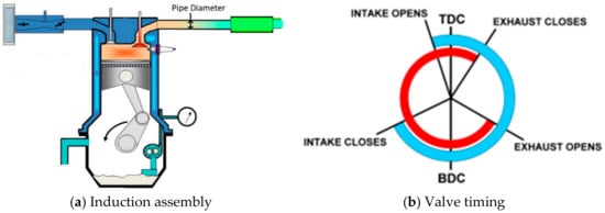
Figure 3.
Conventional engine induction assembly, (a) Induction assembly (b) Valve timing.
This simulation uses the SI Wiebe combustion model and the Woschni heat transfer model as shown in Figure 4. As provided by Ricardo Wave, they are given as follows:
where:
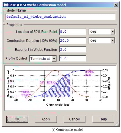
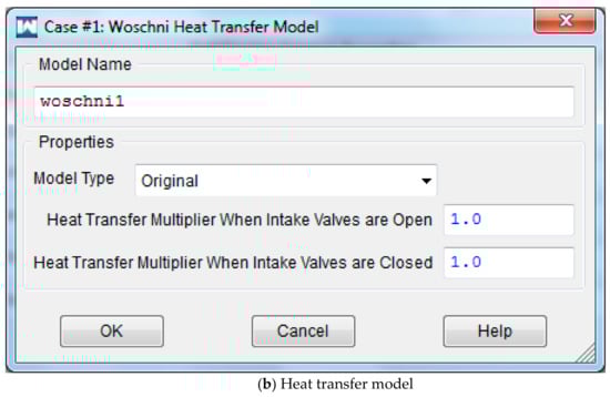
Figure 4.
SI Wiebe combustion model and Woschni heat transfer model in WAVE, (a) Combustion model (b) Heat transfer model.
- f = mass fraction burn;
- = crank angle;
- = angle of the start of the heat addition;
- = combustion duration;
- = efficiency parameter;
- m = shape factor.
- h = heat transfer coefficient;
- b = cylinder bore;
- P = cylinder pressure;
- T = cylinder temperature;
- v = average gas velocity;
- C = user entered multiplier.
2.2.1. Variable Runner Diameters
The Helmholtz Resonance theory works on the principle of acoustic resonance. As air tries to ram into a resonator through a pipe/chamber, the column of air begins to flow as compression and rarefaction waves. This wave keeps travelling unless it encounters an abrupt change in cross-section, which could be a step, a collector or an opening to the atmosphere. These waves have energy, tone and amplitude and travel at the speed of sound at local temperature. The idea of tuning is to capitalize these pressure waves and make sure that the low-pressure wave arrives exactly at the time the exhaust valve opens.
The occurrence and properties of these pressure waves are governed by the geometry of the exhaust runners. The exhaust pipe diameter governs the velocity and pressure of the flow of these waves. Reducing the cross-section area of flow would increase the flow velocity at the cost of flow-pressure. Whereas, increasing the cross-section area would increase the flow pressure, but at the cost of flow velocity. This would be detrimental to engine scavenging. The optimal cross-section area of flow would be a function of engine speed. Hence, varying the flow cross-section area i.e., the exhaust pipe diameter with respect to engine speed will provide more effective control on these pressure waves and provide a boost to the engine performance [10,15,37].
For further simulations to optimize the exhaust port diameter, the initial optimal cross-sectional area of the exhaust pipe is found using the formula given by Baechtel [16] and Bell [38]. In equation form:
where:
- Ac/s = primary pipe cross sectional area (square meters)
- V = volume of one single cylinder (cubic meters)
- rpm = Engine speed (revolutions per minute)
- 88,200 = constant of proportionality
After calculating the ideal cross-sectional area, the ideal pipe size (diameter) is found using the equation given by Baechtel [16] which is shown below:
where:
- Ac/s = primary pipe cross sectional area (square meters)
- 1.273 = constant of proportionality
The pipe diameter obtained from this formula serves only as the starting point. To get the optimum pipe diameters for each speed the engine performance needs to be simulated and tested around the theoretically calculated values until the peak performance is attained. Accordingly, the diameter is varied from 33 mm to 60 mm in steps of 3 mm which includes the stock diameter of 46.04 mm.
2.2.2. Variable Valve Timings
Exhaust valve closing timing is an important parameter as it determines the amount of exhaust charge that is retained in the cylinder. It is desired to emit as much exhaust gas as possible to make space for the fresh charge to be entered into the cylinder in the intake stroke. Another significance of the exhaust closing event is that the EVO event is the major reason for the occurrence of compression and rare-faction pressure waves in the exhaust runner. It is important to open the exhaust gas exactly at the time the negative pressure wave arrives just behind the valve. This creates a low-pressure zone behind the exhaust valve. This increases the pressure differential between the gases in the combustion chamber and the cavity in the exhaust runner, thus helping the scavenging process. The speed and frequency of this low-pressure wave is a function of engine operating speed. Hence, varying the exhaust opening and the closing event with respect to engine speed will allow enhanced control on these pressure waves and help boost the engine performance [39,40,41].
2.2. Validation
To validate the data gathered from the 1-D simulation in Ricardo WAVE software, the engine fitted into a FSAE car is tested on a chassis dynamometer from 5500 to 7500 rpm. Brake torque and power are compared between the dynamometer and the simulation as shown in Figure 5 [15,37,41].
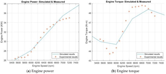
Figure 5.
Engine performance vs engine speed- simulation results validated against experimental torque [15,37,41], (a) Engine power (b) Engine torque.
The nature of the brake torque and power curves obtained from the dyno test and simulation followed closely and a variance of around 5% is observed. The variations are mainly due the losses such as drive axle losses, drivetrain losses and losses due to friction between the roller and tire which occur from the shaft of the engine to the car wheel standing on the roller of the dynamometer. During simulations these losses are not considered.
3. Results and Discussion
The engine performance is simulated from 2000 to 11,000 rpm in increments of 200 rpm. The effects of variable exhaust runner diameter and variable exhaust valve timing on engine performance are observed.
3.1. Exhaust Pipe Diameter
The exhaust pipe diameter is varied from 33 to 60 mm in steps of 3 mm. The original diameter is 46.04 mm. The direct effect of variable diameter at different speeds on engine torque can be viewed in Figure 6 and Table 2. In the table, the dark green color denotes values at which least torques are obtained, followed by yellow, which shows values for torques lying in the middle range, and dark red color denotes the peak values for each engine speed. Figure 6a appears to undergo more changes than Figure 6b,c. It should be noted that the modeled engine is not generally intended to operate under 3000 rpm, and usually runs above 5000 rpm. The effects of increasing diameter for most engine speeds wanes once it reaches roughly 50 mm. From here, increasing the diameter produces diminishing returns in most cases. Figure 6b shows a transition phase of the engine. From 5500 to 6500 rpm, there is a small drop in torque only for it to increase again. This could be the rarefaction wave arrival time not coinciding with valve overlap timing. This parabolic wave motion can be seen in any of the diameter plots. Once speed is above 6000 rpm, the wave motion almost completely levels off when the diameter reaches 50 mm. This trend can be seen in Figure 6c.
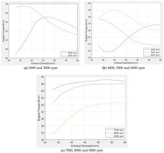
Figure 6.
Effects of exhaust pipe diameter at specific speeds, (a) 2000 and 3000 rpm (b) 4000, 5000 and 6000 rpm (c) 7000, 8000 and 9000 rpm.
Table 2.
Torques at optimized pipe diameters.
Figure 7 gives a closer look as to why there are inflections and changes to the wave motion at certain points. The diameter is held constant at its original value of 46.04 mm for these plots, while only the speed is adjusted. The crank angle starts at 109 degrees to designate where the EVO event occurs. For all the engine speeds shown, the exhaust valve is opened almost where the lowest point of the pressure wave occurs. In the simulations, a pressure sensor is attached just 5 mm above the exhaust valve to closely monitor the static pressure near the exhaust valve. Figure 7a shows the exhaust port pressure waves at 4000 and 5000 rpm. At 4000 rpm, the pressure at EVO is less than 1 bar, thus the pressure is sub-atmospheric. This indicates that a rarefaction wave arrives at the exhaust valve at the EVO event. Since the pressure is lower than atmospheric, more gas is pushed out of the exhaust valve while also bringing in more fresh charge. This increases scavenging in the engine [16,42]. At 5000 rpm, a compression wave greater than 1 bar arrives at EVO. This reduces the amount of intake charge flow when the intake valve opens. Figure 6b supports this finding. At roughly 46 mm, engine performance increases for 4000 rpm, but decreases for 5000 rpm. A similar effect for 6000 and 7000 rpm can be seen in Figure 7b.
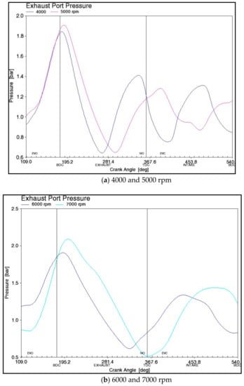
Figure 7.
Exhaust port pressures at various speeds, (a) 4000 and 5000 rpm (b) 6000 and 7000 rpm.
Figure 8 represents the ideal diameter at each speed of the engine. At these values, the maximum engine torque is accomplished. In real world applications, it may be difficult to have a pipe that changes diameter as frequently as what is shown in Figure 8. It may be more cost effective to have an exhaust set-up that only varies across a few different diameter sizes. For instance, a 36 mm diameter pipe is roughly the optimal diameter across several speeds. Another size could be 60 mm and another could be 45 mm.
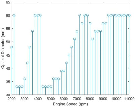
Figure 8.
Optimal diameters for each engine speed.
Having three different exhaust pipe diameter would be superior to have only one pipe diameter. Hence, it is chosen to operate the variable diameter assembly with only three sets of exhaust pipe diameters as can be seen in Figure 9. This will reduce the gain in the torque, but will still keep the engine torque considerably higher than the one obtained from fixed exhaust setup.
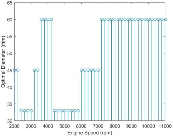
Figure 9.
Three-diameter exhaust setup—Optimal diameters for each engine speed.
Figure 10 shows the gain in engine torque as an effect of variable diameter runner set up. The engine torque increases by an average of 4.23% by continuously varying the exhaust pipe diameters at all engine speeds. When we consider the more practical and feasible option of having only three variations in the exhaust runner diameters, the engine torque still increases at all engine speeds except at the lower engine speed of 2200 rpm. Since this is a high revving engine whose idling speed itself would be above 2000 rpm, this slight reduction in the engine torque could be considered as negligible. With this set-up, the average increase in engine torque is 3.78%. To make up for the loss of gain in the engine torque because of considering a more practical setup, exhaust valve opening and closing time are further varied, keeping the valve open duration constant.
Figure 10.
Comparison of (i) Fixed Exhaust Diameters; (ii) Infinitely Variable Exhaust Diameters; (iii) Variable Exhaust Diameters (3 Variations).
3.2. Exhaust Valve Timing
After testing the effects of varying diameter only, the effects of valve timing only are tested. Valve timings are varied from 80 to 120 degrees ATDC in steps of 2 degrees. The original angle is 109 degrees ATDC. The valve duration is held constant. Figure 11 shows the effect of changing the exhaust valve opening timing on engine torque. Valve timing has less of an impact than diameter. Continuous valve timing alone shows an average torque improvement of 1.94% than the original model. A valve timing between 90 and 105 degrees usually contains the largest torque. Similarly to the data found by Kesgin [20], once the EVO angle exceeds 109 degrees, the quality of the performance of the engine starts to decline as can be seen in Figure 11. Likewise to varying the diameter, torque increases while speed increases up to about 4000 rpm. After that, the torque declines and then increases again at around 5500 rpm. Performance drops steadily after 7000 rpm.


Figure 11.
Effects of valve opening timing at specific speeds, (a) 2000 and 3000 rpm (b) 4000, 5000 and 6000 rpm (c) 7000, 8000 and 9000 rpm.
3.3. .Combined Variation of Exhaust Runner Diameter and Exhaust Valve Timing
In order to maximize the performance of the engine, a combination of variable diameter and valve timing needs to occur. For this research, the maximum torque is recorded for each case: original exhaust assembly, variable diameter only (case I), variable diameter (3 diameters) and valve timing together (case II). At each speed, the maximum torque is recorded for all cases. The maximum values for torque are plotted in Figure 12.
Figure 12.
Percent increase in brake torque for (i) Original Exhaust Setup; (ii) Practical Variable Diameters (3 variations); and (iii) Variable Diameters (3 variations) & Variable Valve timings.
These maximum torque values are compared to the original model, independent of changes. The figure shows that all two cases produce visibly more torque than the original model at all engine speeds except around 6500 rpm. The gains in torque using pipes of three diameters are less than the gains using infinitely variable diameters. However, using pipes of three diameters and the addition of the variable valve timing recover that losses. Continuously varying the diameter shows an average torque improvement of 4.23% than the original model. However, when the variation of diameter is limited to three diameters of 36 mm, 45 mm and 60 mm, the average improvement of torque is reduced to 3.78%. The addition of variable valve timings increase the torque output by an average of 4.69%, which is 0.91% addition to the increase obtained by three steps variable diameter exhaust diameters alone.
4. Conclusions
The effects of exhaust manifold tuning by varying the pipe diameter and exhaust valve timing have been simulated and studied. The simulation is carried out using Ricardo Wave software. The analysis shown concludes that varying the exhaust runner diameter and the exhaust valve timing can influence the torque of the engine. Of the two parameters viewed, the diameter has a greater effect than valve timing. Both can be varied simultaneously to produce the best results. Varying only the exhaust diameter continuously with speed improves the torque on average by 4.23%. However, varying the diameter continuously will be difficult to implement in a real-world situation. It may be more practical to vary valve timings across an extensive range, while varying the diameter only across several key values that produce the best torque. As an effort to overcome the practical limitations of varying the diameter continuously, only three variations (36 mm, 45 mm and 60 mm) are made to the exhaust pipe diameters ensuring that the research proposes a feasible, packable and cost-efficient approach for exhaust manifold tuning compared to infinitely variable diameter exhaust manifold assembly. Varying the diameter alone in three steps produces an average 3.78% improvement in torque and varying the diameter and valve timing together has a 4.69% improvement in torque. Butterfly valves can be used to direct the exhaust gas to different diameter pipes. The technology to use different pipes at different speeds are already in use in Mahindra 2 wheelers [43] and Toyota’s Acoustic Control Induction System (ACIS) [44,45]. They use this technology to switch to different length pipes for the intake runner at different speeds. A similar approach can be utilized for the proposed exhaust system in this research. Several telescopic pipes that changes at different speeds, could also be implemented. Such a system can improve the torque of gasoline engines without super- or turbo-charger.
Author Contributions
M.W. did the initial simulations and wrote the first draft. P.S. ran the simulations again to add more results and rewrote the paper. S.B. supervised both M.W. and M.W. to conduct this research and also, helped them to write the paper.
Conflicts of Interest
The authors declare no conflicts of interest.
Abbreviations
| EVO | Exhaust Valve Opening |
| EVC | Exhaust Valve Closing |
| IVO | Intake Valve Opening |
| IVC | Intake Valve Closing |
| BTDC | Before Top Dead Center |
| ATDC | After Top Dead Center |
| BBDC | Before Bottom Dead Center |
| ABDC | After Bottom Dead Center |
| rpm | Revolutions per Minute |
References
- Blair, G.P.; Mackey, D.; Ashe, M.; Chatfield, G. Exhaust Tuning on a Four-Stroke Engine; Experimentation and Simulation; 0148-7191; SAE Technical Paper; SAE International: Warrendale, PA, USA, 2001. [Google Scholar]
- Saad, I.; Bari, S. Effects of guide vane swirl and tumble device (gvstd) to the air flow of naturally aspirated ci engine. In Proceedings of the 9th International Conference on Mechanical Engineering (ICME2011), Dhaka, Bangladesh, 18–20 December 2011; Progressive Printers Pty. Ltd.: Dhaka, Bangladesh, 2011; pp. 1–6. [Google Scholar]
- Tabaczynski, R.J. Effects of inlet and exhaust system design on engine performance. In Proceedings of the SAE International Congress and Exposition, Detroit, MI, USA, 22–26 February 1982; SAE Technical Paper 821577; pp. 1–12. [Google Scholar]
- Saad, I.; Bari, S. Optimize vane length to improve in-cylinder air characteristic of ci engine using higher viscous fuel. Appl. Mech. Mater. 2013, 393, 293–298. [Google Scholar] [CrossRef]
- Saravanan, D.; Gokhale, A.; Karthikeyan, N. Design and development of a novel charge boosting system for a single cylinder si engine. In Proceedings of the SAE 2014 World Congress & Exhibition, Detroit, MI, USA, 8–10 April 2014; SAE Technical Paper 2014-01-1707; pp. 1–10. [Google Scholar]
- Liu, K.; Yang, J.; Jiang, W.; Li, Y.; Wang, Y.; Feng, R.; Chen, X.; Ma, K. Effect of asynchronous valve timing on combustion characteristic and performance of a high speed si marine engine with five valves. Energy Convers. Manag. 2016, 123, 185–199. [Google Scholar] [CrossRef]
- Saad, I.; Bari, S. Cfd investigation of in-cylinder air flow to optimize number of guide vanes to improve ci engine performance using higher viscous fuel. Int. J. Automot. Mech. Eng. 2014, 8, 1096–1107. [Google Scholar] [CrossRef]
- Bari, S.; Saad, I. Performance and emissions of a compression ignition (ci) engine run with biodiesel using guide vanes at varied vane angles. Fuel 2015, 143, 217–228. [Google Scholar] [CrossRef]
- Ghodke, S.; Bari, S. Effect of integrating variable intake runner diameter and variable intake valve timing on an si engine’s performance. In Proceedings of the WCX World Congress Experience, Detroit, MI, USA, 10–12 April 2018; SAE Technical Papers. [Google Scholar]
- Aradhye, O.; Bari, S. Continuously varying exhaust pipe length and diameter to improve the performance of a naturally aspirated si engine. In Proceedings of the ASME International Mechanical Engineering Congress and Exposition, Tampa, FL, USA, 3–9 November 2017. [Google Scholar]
- Gajula, V.; Bari, S. Performance tuning of an ic engine based on pressure wave propagation with a continuously variable exhaust runner length and exhaust valve timing system. In Proceedings of the ASME International Mechanical Engineering Congress and Exposition, Tampa, FL, USA, 3–9 November 2017. [Google Scholar]
- Cairns, A.; Zhao, H.; Todd, A.; Aleiferis, P. A study of mechanical variable valve operation with gasoline–alcohol fuels in a spark ignition engine. Fuel 2013, 106, 802–813. [Google Scholar] [CrossRef]
- Benajes, J.; Reyes, E.; Bermudez, V.; Serrano, J. Pre-design criteria for exhaust manifolds in ic automotive engines. In Proceedings of the International Congress & Exposition, Detroit, MI, USA, 23–26 February 1998; SAE Technical Paper; ISSN 0148-7191. [Google Scholar]
- Bush, P.; Telford, C.; Boam, D.; Bingham, J. A design strategy for four cylinder si automotive engine exhaust systems. In Proceedings of the SAE 2000 World Congress, Detroit, MI, USA, 6–9 March 2000; SAE Technical Paper; ISSN 0148-7191. [Google Scholar]
- Sawant, P.; Bari, S. Combined effects of variable intake manifold length, variable valve timing and duration on the performance of an internal combustion engine. In Proceedings of the ASME International Mechanical Engineering Congress and Exposition, Tampa, FL, USA, 3–9 November 2017. [Google Scholar]
- Baechtel, J. Performance Automotive Engine Math; CarTech: Lakeland, FL, USA, 2011. [Google Scholar]
- Monroe, T. Users Guide and Engine Builder’s Handbook; HPBooks: Toronto, ON Canada, 1996. [Google Scholar]
- Ibrahim, A.; Bari, S.; Bruno, F. A study on egr utilization in natural gas si engines using a two-zone combustion model. In Proceedings of the JSAE/SAE International Fuels & Lubricants Meeting, Kyoto, Japan, 23–26 July 2007; SAE Technical Paper 2007-01-2041; pp. 1–10. [Google Scholar]
- Deshmukh, D.; Kumar, R.; Garg, M.; Nayeem, M.J.; Lakshminarasimhan, V. Optimisation of Gas Exchange Process on a Single Cylinder Small 4-Stroke Engine by Intake and Exhaust Tuning: Experimentation and Simulation; 0148-7191; SAE Technical Paper; Society of Automotive Engineers: Warrendale, PA, USA, 2004. [Google Scholar]
- Kesgin, U. Study on the design of inlet and exhaust system of a stationary internal combustion engine. Energy Convers. Manag. 2005, 46, 2258–2287. [Google Scholar] [CrossRef]
- Costa, R.C.; Hanriot, S.d.M.; Sodré, J.R. Influence of intake pipe length and diameter on the performance of a spark ignition engine. J. Braz. Soc. Mech. Sci. Eng. 2014, 36, 29–35. [Google Scholar] [CrossRef]
- Sammut, G.; Alkidas, A.C. Relative contributions of intake and exhaust tuning on si engine breathing—A computational study. In Proceedings of the SAE World Congress & Exhibition, Detroit, MI, USA, 16–19 April 2007; SAE Technical Paper 2007-01-0492; pp. 1–19. [Google Scholar]
- Fontana, G.; Galloni, E. Variable valve timing for fuel economy improvement in a small spark-ignition engine. Appl. Energy 2009, 86, 96–105. [Google Scholar] [CrossRef]
- Jia, M.; Xie, M.; Wang, T.; Peng, Z. The effect of injection timing and intake valve close timing on performance and emissions of diesel pcci engine with a full engine cycle cfd simulation. Appl. Energy 2011, 88, 2967–2975. [Google Scholar] [CrossRef]
- Gölcü, M.; Sekmen, Y.; Erduranlı, P.; Sahir Salman, M. Artificial neural-network based modeling of variable valve-timing in a spark-ignition engine. Appl. Energy 2005, 81, 187–197. [Google Scholar] [CrossRef]
- Ibrahim, A.; Bari, S. An investigation on using egr in natural gas si engine. In Proceedings of the International Conference on Mechanical Engineering, Dhaka, Bangladesh, 29–30 November 2007; BUET: Dhaka, Bangladesh, 2007; p. Th-23. [Google Scholar]
- Bonatesta, F.; Altamore, G.; Kalsi, J.; Cary, M. Fuel economy analysis of part-load variable camshaft timing strategies in two modern small-capacity spark ignition engines. Appl. Energy 2016, 164, 475–491. [Google Scholar] [CrossRef]
- Lee, J.; Lee, K.; Lee, J.; Anh, B. High power performance with zero nox emission in a hydrogen-fueled spark ignition engine by valve timing and lean boosting. Fuel 2014, 128, 381–389. [Google Scholar] [CrossRef]
- Li, Y.; Khajepour, A.; Devaud, C.; Liu, K. Power and fuel economy optimizations of gasoline engines using hydraulic variable valve actuation system. Appl. Energy 2017, 206, 577–593. [Google Scholar] [CrossRef]
- Deng, B.; Yang, J.; Zhang, D.; Feng, R.; Fu, J.; Liu, J.; Li, K.; Liu, X. The challenges and strategies of butanol application in conventional engines: The sensitivity study of ignition and valve timing. Appl. Energy 2013, 108, 248–260. [Google Scholar] [CrossRef]
- Yeom, K.; Jang, J.; Bae, C. Homogeneous charge compression ignition of lpg and gasoline using variable valve timing in an engine. Fuel 2007, 86, 494–503. [Google Scholar] [CrossRef]
- Claywell, M.; Horkheimer, D.; Stockburger, G. Investigation of intake concepts for a formula sae four-cylinder engine using 1d/3d (ricardo wave-vectis) coupled modeling techniques. In Proceedings of the Motorsports Engineering Conference & Exposition, Dearborn, MI, USA, 5–7 December 2006; SAE Technical Paper 2006-01-3652; pp. 1–26. [Google Scholar]
- Silvestri, J.J.; Morel, T.; Costello, M. Study of intake system wave dynamics and acoustics by simulation and experiment. In Proceedings of the International Congress & Exposition, Chicago, IL, USA, 6–11 November 1994; SAE Technical Paper; ISSN 0148-7191. [Google Scholar]
- Winterbone, D.; Yoshitomi, M. The accuracy of calculating wave action in engine intake manifolds. In Proceedings of the International Congress & Exposition, Detroit, MI, USA, 1 December 1990; SAE Technical Paper; ISSN 0148-7191. [Google Scholar]
- Ohata, A.; Ishida, Y. Dynamic inlet pressure and volumetric efficiency of four cycle four cylinder engine. In Proceedings of the SAE International Congress and Exposition, Detroit, MI, USA, 22–26 February 1982; SAE Technical Paper; ISSN 0148-7191. [Google Scholar]
- Manual, O.S. Owner’s Manual 500 EXC US; KTM: Mattighofen, Austria, 2015; Available online: http://ktmamerica.com/part_books/2015/dual%20sport/500%20EXC%20CHASSIS%20PARTS%20MANUAL%202015.pdf (accessed on 12 June 2018).
- Sawant, P. Analysis of Individual, Combined and 2-Step Variation in Induction System of an IC Engine to Optimize Performance and Fuel Efficiency; University of North Carolina: Charlotte, NC, USA, 2018. [Google Scholar]
- Bell, A.G. Performance Tuning in Theory and Practice: FOUR Strokes; Haynes: Kokomo, IN, USA, 1981. [Google Scholar]
- Vodda. The Impact of Valve Events upon Engine Performance and Emissions. Available online: https://www.mechadyne-int.com/app/uploads/2015/05/the-impact-of-variable-valve-actuation-on-engine-performance-and-emissions.pdf (accessed on 1 June 2018).
- Khudhur, S.H.; Saleh, A.M.; Chaichan, M.T. The effect of variable valve timing on sie performance and emissions. Int. J. Sci. Eng. Res. 2015, 6, 173–179. [Google Scholar]
- Sawant, P.; Bari, S. Effects of variable intake valve timings and valve lift on the performance and fuel efficiency of an internal combustion engine. In Proceedings of the WCX World Congress Experience, Detroit, MI, USA, 10–12 April 2018; SAE Technical Papers. [Google Scholar]
- Schweitzer, P.H. Scavenging of Two-Stroke Cycle Diesel Engines; Macmillan Co.: London, UK, 1949. [Google Scholar]
- Khan, S.A.; Ayyappath, P. Design and development of variable valve timing and lift mechanism for improving the performance of single cylinder two wheeler gasoline engine. In Proceedings of the SAE 2014 World Congress & Exhibition, Detroit, MI, USA, 8–10 April 2014; SAE Techincal Paper 2014-01-1699; pp. 1–8. [Google Scholar]
- Hiraku, K.; Fuwa, N.; Yamada, H.; Yamanashi, T. Intake Air Amount Control Apparatus and Method of Internal Combustion Engine. U.S. Patent 6,834,627, 28 December 2004. [Google Scholar]
- Grutter, P.J.; Lipinski, D.J.; LoRusso, J.A.; Nowland, D.R.; Prior, E.C.; Robichaux, J.D. Air Induction Control System for Variable Displacement Internal Combustion Engine. U.S. Patent 5,431,139, 11 July 1995. [Google Scholar]
© 2018 by the authors. Licensee MDPI, Basel, Switzerland. This article is an open access article distributed under the terms and conditions of the Creative Commons Attribution (CC BY) license (http://creativecommons.org/licenses/by/4.0/).