Multiple Phase Change Material (PCM) Configuration for PCM-Based Heat Sinks—An Experimental Study


Environment and Sustainability Institute, University of Exeter, Penryn Campus, Cornwall TR109FE, UK
*
Author to whom correspondence should be addressed.
Energies 2018, 11(7), 1629; https://doi.org/10.3390/en11071629
Submission received: 1 June 2018
/
Revised: 19 June 2018
/
Accepted: 20 June 2018
/
Published: 22 June 2018
(This article belongs to the Section D: Energy Storage and Application)
Abstract
:A small-scale phase change material (PCM)-based heat sink can regulate the temperature of electronics due to high latent-heat capacity. Three different heat sinks are examined to study the effects of PCM combination, arrangement of PCMs in multiple-PCM heat sink, PCM thickness, melting temperature and intensity of heat source on the thermal behavior of heat sink. Results are obtained for the temperature distribution across the heat sink and the PCM melting profile. It is concluded that (i) PCM combination RT50–RT55 increases the thermal regulation period and also reduces the heat sink temperature at the end of the operation, (ii) the RT58–RT47 arrangement slightly reduces the maximum temperature as compared to RT47–RT58, (iii) As PCM thickness increases from 30 mm to 60 mm, the thermal-regulation-period increases by 50 min, (iv) As the PCM melting temperature increases, the thermal-regulation-period and the heat sink temperature increase and (v) The thermal-regulation-period decreases as the power rating increases from 1 to 2 W.
1. Introduction
Thermal management of electronics is an important issue, because the heat generated by an electronic system leads to a decrease in its efficiency or even an immediate failure [1]. The heat-related failures of electronics account for 55% of the total electronic failures as per a U.S. Air Force survey [2]. The component failure increases by 100% for a temperature increase between 10 °C and 20 °C [3] whereas the component failure reduces at a rate of approximately 4%/°C with a decrease in the temperature. This issue has become even more challenging for higher performance complex electronic systems such as smart phones and notebook computers as they are required to be light in weight and small in size [4].
Many studies have emphasized the thermal management of electronic devices and have proposed various techniques for cooling such as extended surface [5], cold plates [6], immersion cooling [7], heat pipes [8] and thermoelectric coolers [9]. Selection of the cooling technique depends on the operating temperature, heating power rate, available space and cost [10]. The limitation of these techniques is that the excessive heat must be extracted to the environment using ventilation slots. But in wet and dusty environments, the devices must be completely sealed. An integrated thermal energy storage (TES) system within the device could solve this issue.
Thermal regulation of electronics using phase change material (PCM) is considered as a promising cooling technique due to the attractive features of PCM such as high storage density, ability to withstand a large number of cycles and isothermal nature at relatively constant melting temperature [11,12,13,14]. It was first proposed for avionics thermal control in 1977 [15] and since then a lot of studies investigated the PCM-based heat sink [16,17,18,19,20,21,22,23,24]. The main drawback of the PCM is its low conductivity which has led researchers to propose various enhancement techniques such as using extended surfaces of different configurations [25,26,27,28], employing multiple PCMs [29] and PCM encapsulation [30].
Many factors affect the performance of PCM-based heat sinks for electronics applications such as the container orientation [31,32,33,34], quantity of PCM [35,36], heating rate and PCM melting temperature. Kandasamy et al. [23,37] reported a numerical and experimental investigation of cooling of electronics using PCM. The studies conducted a comparison of heat sinks with and without PCM and examined the effect of heating power level of a horizontal uniform heat source ranging from 2 to 6 W. It was shown that a PCM heat sink has a major effect in improving the cooling performance compared to a non-PCM heat sink. Fok et al. [38] concluded that using a PCM in a heat sink has two advantages compared to a non-PCM heat sink such as (i) the PCM heat sink maintains the electronics at a lower temperature compared to a non-PCM heat sink and (ii) the rate of temperature rise of PCM’s heat sink is lower compared to a non-PCM heat sink during the absorption of latent heat.
The selection of the melting temperature of PCM is a key factor in designing an efficient PCM heat sink. Fan et al. [26] investigated the importance of selection of the PCM melting temperature in a horizontal heat sink arrangement with a heating source ranged between 60 to 120 W. The used PCMs were eircosane and hexadecanol. The study showed that a longer thermal regulation period (the duration for which the heat sink is maintained at low temperature) is achieved when using a higher melting temperature of PCM. However, the lower PCM melting temperature performs better in terms of reducing the maximum temperature in a short period. Mahmoud et al. [39] studied the PCM-based heat sink for a heating rate ranging from 3 to 5 W for six types of paraffin wax for a horizontal heat sink. The results showed that the maximum operating temperature was reduced by 10 °C when the PCM melting temperature reduced from 42 to 29 °C. Huang et al. [40] studied the effect of PCM melting temperature in thermal regulation of PV for a constant insolation of 750 W/m2. The results indicated that using PCM with a melting temperature of 25 °C is better than PCM with a melting temperature of 43 °C in reducing the temperature by 15 °C for 150 min. Wang et al. [41] conducted a parametric study of the PCM heat sink, examining the effect of temperature difference between the heat source and the melting point of the PCMs on the heat sink performance. The results showed that the greater the temperature difference between the heat source and the PCM’s melting temperature, the higher the melting speed. On the other hand, the PCMs with lower melting temperature reduced the heat sink temperatures, as concluded by Mahmoud et al. [39].
Also, the amount of PCM used in the heat sink plays an important role in the heat sink size, weight and cost. Arshad et al. [42] experimentally studied the effect of the PCM fraction in a horizontal PCM heat sink arrangement. The results showed that the fully filled heat sink with PCM performs better than the heat sink filled with PCM volume fractions of 0.33 and 0.66. Saha et al. [43] also examined experimentally and numerically the effect of PCM fraction for a similar type of PCM heat sink with heating rate ranging between 4 and 8 W. The study found that the heat sink performance was better when using a PCM fraction of 88% compared to a full PCM heat sink. Tomizawa et al. [44] studied the effect of PCM thickness in the cooling of mobile device applications. The results show that thicker PCM results in a longer operating period.
Using two PCMs in the heat sink is considered as a thermal conductivity enhancement technique as highlighted earlier, and very few works investigated this approach for electronics heat sink applications. Emam and Ahmed [45] studied numerically the effect of using three PCMs series cavities heat sink in concentrated photovoltaics (CPV) applications of 20 concentration ratio system. The selected PCM melting temperature range is between 22.5 to 29.8 °C. The results showed that medium-low-high PCM melting temperature arrangement is the best in terms of reducing the solar cell maximum temperature (average temperature of 106 °C) for an operating time of 120 min. In a similar study of using multiple PCMs heat sink in application of thermal regulation of solar cell, Huang [29] explored numerically two types of arrangements of two PCMs of triangular cells and semi-circular cells under actual operating conditions. The PCM melting temperature is ranging between 27 to 60 °C. The author concluded that higher-lower PCM melting temperature order achieves the highest temperature drop during the daily operation. Shaikh and Lafdi [46] studied numerically the effect of multiple PCMs in different arrangements. The study has found that using composite PCMs with different melting temperatures can significantly enhance the total energy charged compared to single PCM.
Even though several investigations have been carried out to study the performance of the PCM heat sinks for electronics thermal regulation, few studies investigated two PCMs in a heat sink. Therefore, the aim of the present work is to experimentally investigate the effect of multiple-PCM heat sink, PCM thickness, melting temperature and intensity of heat source on the thermal behavior of a heat sink.
2. Experimental Setup and Procedure
The experimental setup is designed to identify the effect of different parameters mentioned above. Hence, four heat sinks (one no-PCM heat sink and three PCM heat sinks) have been manufactured to examine the effect of PCM, PCM thickness and the 2 PCM arrangements. The no PCM heat sink consists of a heat source attached to a metal plate. The other three PCM heat sinks are denoted by A, B and C and are made up of clear acrylic to monitor the PCM melting profile with inner dimensions of 30 × 30 × 30 mm, 60 × 30 × 30 mm and 62 × 30 × 30 mm, respectively, as shown in Figure 1. Heat sinks A and B (Figure 1a) have one cavity to be filled with one type of PCM. Heat sink C (Figure 1b) has two cavities and thus to be filled with two different types of PCMs of sizes 30 × 30 × 30 mm each. The two cavities are separated using a 2 mm thick aluminum plate. An aluminum plate of 2 mm thickness has been fixed on one side of the container for heating the PCM and insulated thermally using polystyrene. The experimental setup is shown in Figure 1c.
An electrical flexible heater (Omega KHLV, OMEGA Engineering INC., Norwalk, CT, USA) has been used to simulate the generated heat by electronics. Different heating power ratings have been used through DC power supply by varying the voltage.
K type thermocouples are used for the temperature measurements. The thermocouples are fixed inside the container to measure the PCM temperature distribution across the container and also the aluminum plate temperature. The thermocouple T1 is placed on the middle of the inner surface of the aluminum plate to measure the heater temperature as shown in Figure 2. The thermocouples from T2 to T5 are placed to measure the temperature of the PCM along the direction of the heat flow and are located 15 mm apart. A thermocouple (T6) is kept outside to measure the ambient temperature. The temperature measurements are recorded with an interval of 5 s using data acquisition system (OMEGA RDXL 12 SD, OMEGA Engineering INC., Norwalk, CT, USA). A digital camera has been used to capture images of the heat sink with a time interval of 20 min to observe the melting profile of the PCM. The thermocouples have been calibrated using the ambient temperature and the boiling water temperature (100 °C). The error in the temperature measurement is found to be less than 0.4% using a standard thermometer having a reading resolution of 0.1 °C.
In order to analyze the effect of PCM melting temperature on the performance of heat sink, RT46, RT49, RT52, RT55 and RT58 with melting temperature of 46 °C, 49 °C, 52 °C, 55 °C and 58 °C, respectively, are used which have same latent heat capacity (170 kJ/kg), density in liquid-phase (770 kg/m3), density in solid-phase (880 kg/m3) and thermal conductivity (0.2 W/mK). To fill the PCM container, the PCM was melted initially. Then, the melted PCM was poured into the container. Before starting each experiment, it is made sure that the PCM is obtained at its initial temperature equal to the ambient value.
3. Results and Discussion
3.1. Comparison of Heat Sink with and without PCM
The heat sinks have been tested with and without PCM filled in the containers. The temperature measurements have been recorded until the steady state conditions were reached. It has been found that the heat sink temperature (without PCM) increased rapidly and the temperature during steady state reached 66 °C, 109 °C and 133 °C for power ratings of 1.0 W, 1.5 W and 2.0 W, respectively. This rapid increase in temperature in electronic devices is not desired and affects their performance.
Figure 3 shows a comparison between the heat sink temperature during the thermal regulation period for heat sink filled with PCM (RT47) and without PCM. The heat sink temperature is markedly decreased compared to no PCM heat sink by 10.8 °C, 50.1 °C and 69.8 °C for 1.0, 1.5 and 2.0 W power ratings, respectively. The temperature drop (achieved using PCM) increases as the power rating increases. The results also show that the duration of thermal regulation is inversely proportional to the heater power for the same amount of PCM.
3.2. Effect of Heater Power Rating
To study the effect of power rating, heat sink A has been filled with RT47 PCM and heated up through 1.0 W, 1.5 W and 2 W power, and the surface temperature for different ratings is shown in Figure 4. The heater has been operated for 210 min in all the experiments. The PCM is not fully melted and the maximum heat sink surface temperature is 56.8 °C at 1.0 W power rating. It can be observed that during latent heat absorption, PCM keeps the heat sink temperature constant. However, the heat sink temperature in this area is much higher than the PCM melting temperature and this should be taken into consideration in designing PCM heat sinks. Also, the thermal regulation period significantly decreases as the power rating increases from 1.0 to 2.0 W. By the end of the charging period, the heat sink surface temperature becomes constant for all the power ratings.
The PCM melting pattern (Figure 5) is defined as the shape of the two phases of the PCM during the melting process. It is considered an important measure in any thermal storage system because it indicates the heat transfer behavior of the system. Figure 5 shows the melting profile for RT47 for different power ratings at 20 min time interval. The general melting profiles of all the power ratings are the same for all PCMs. It is observed that the PCM near to the heat source melts faster and the solid PCM displaces downward and the liquid PCM is pushed upward resulting the curved PCM shape.
The effect of PCM thermal conductivity on the melting of PCM is explored by studying the temperature distribution across the heat sink as shown in Figure 6. It is noted that the heat sink temperature at front (T1) increases faster than the PCM located at the middle (T2) and the rear (T3) of the heat sink at the beginning of the operation. This is due to the low thermal conductivity of the PCM which causes a huge temperature difference between T1 and the other two temperature points and leads to delay in the melting of the PCM at rear as compared to PCM at front. It must also be noted that the high latent heat capacity also leads to delay in complete melting. As an example, the PCM with latent heat capacity of 245 kJ/kg takes three times longer for complete melting as compared to PCM with latent heat capacity of 110 kJ/kg [47].
3.3. Effect of PCM Melting Temperature
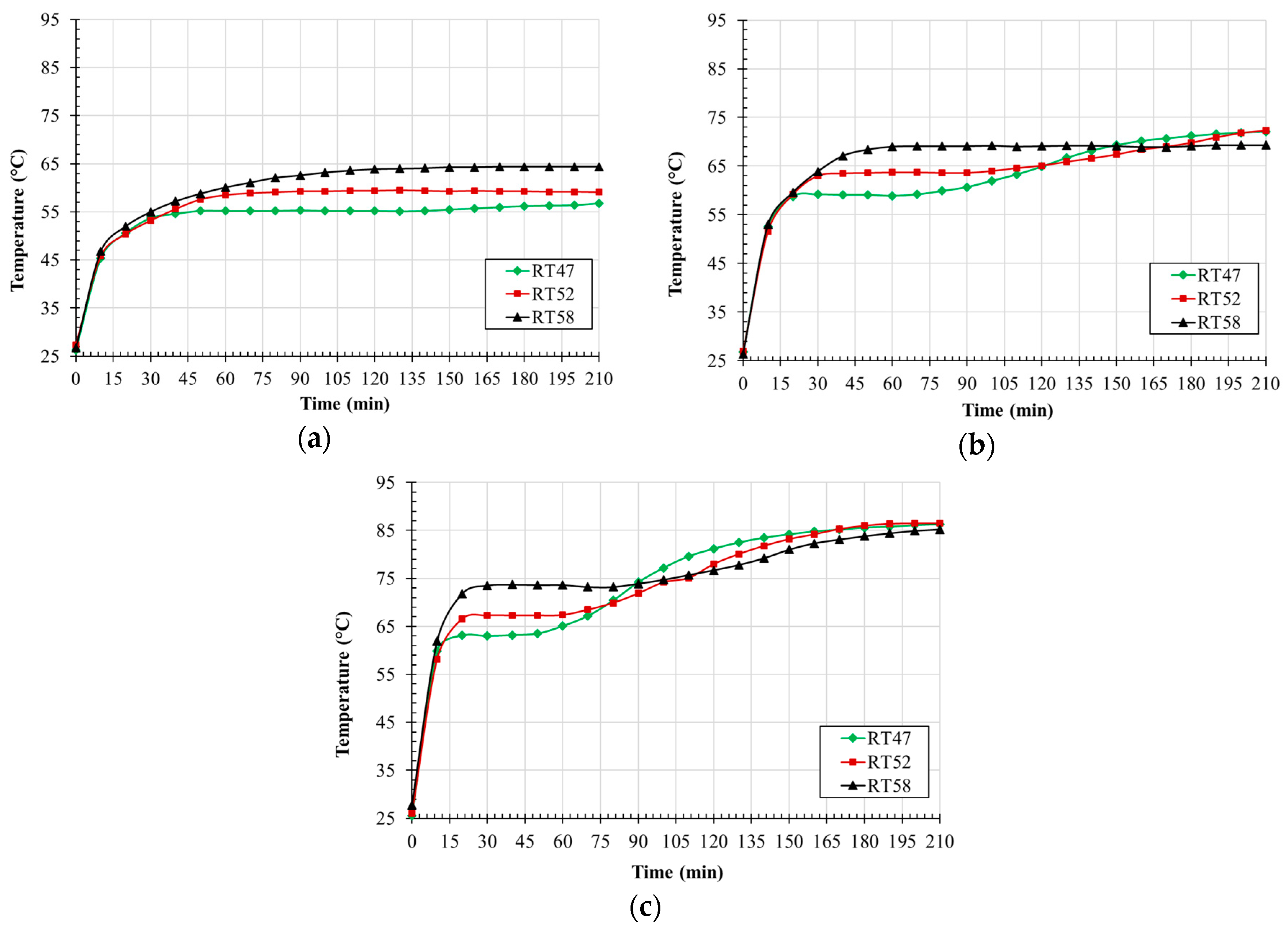
In order to study the effect of PCM melting temperature on the heat sink thermal regulation, different PCMs have been examined. Heat sink A has been used and tested for 3.5 h. The tested PCMs are RT47, RT52, and RT58 with melting temperatures of 47 °C, 52 °C and 58 °C, respectively. Figure 7 shows the heat sink surface temperature (T1) for 1.0, 1.5 W and 2.0 W power ratings for RT47, RT52 and RT58. The results show that the heat sink thermal regulation temperature of RT47 is lower than those of RT52 and RT58. This is because RT47 PCM starts melting earlier than the other two PCMs and starts absorbing heat in latent form. The thermal regulation period for RT47 is shorter compared to those of RT52 and RT58. For 2.0 W, the thermal regulation periods for RT47, RT52 and RT58 are 50, 60 and 90 min, respectively. Therefore, RT47 is suitable to reduce the heat sink maximum temperature for 2.0 W power rating if the charging time is less than 50 min. Also, RT58 is able to reduce slightly the heat sink temperature by the end of the testing period compared to RT47 and RT52 for the power ratings of 1.5 W due to incomplete melting of RT58.
The two most important criteria to design a heat sink for cooling electronics are the thermal regulation temperature during the phase change and the heat sink temperature by the end of the charging period (maximum temperature). These temperature values are summarized in Table 1 for different PCMs and power ratings. For 1.5 W, the maximum heat sink temperature is reduced by about 5 °C by using RT58 instead of RT47. The complete melting of the PCM should be ensured by the end of the charging process for perfect utilization of the PCM.
The melting profiles of different PCMs using 1.5 W power rating at 20 min interval are shown in Figure 8. By the end of the first 20 min, RT47 and RT52 have started melting and no melting has been noticed for RT58. By 100 min of charging, all the PCMs adjacent to the heater have melted completely and RT47 has melted faster than the other two types of PCMs.
3.4. Effect of PCM Thickness on Heat Sink Temperature
The PCM thickness is an important parameter to investigate as it determines the heat sink size and its effect has been investigated using heat sink A (30 mm thick) and heat sink B (60 mm thick). Figure 9 and Figure 10 show the effect of the PCM thickness in the heat sink temperature for RT47 and RT58, respectively. As expected, the PCM is able to maintain the heat sink at lower temperature for longer duration as the PCM thickness increased. Hence, a longer thermal regulation period is expected for the electronics for a thicker PCM. As shown in Figure 9, the PCM thickness has no effect on reducing the maximum heat sink surface temperature for 1.0 and 1.5 W whereas the maximum heat sink surface temperature has been increased by 8 °C for the 2.0 W power rating.
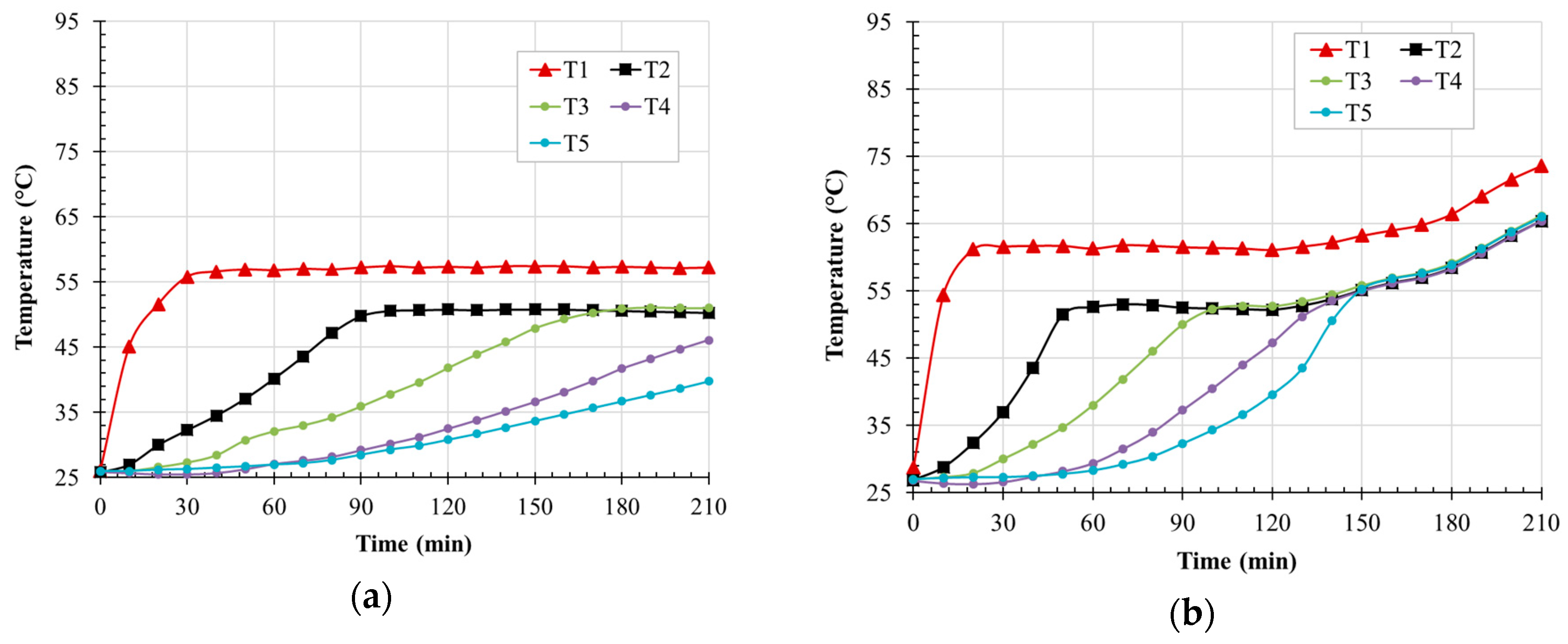
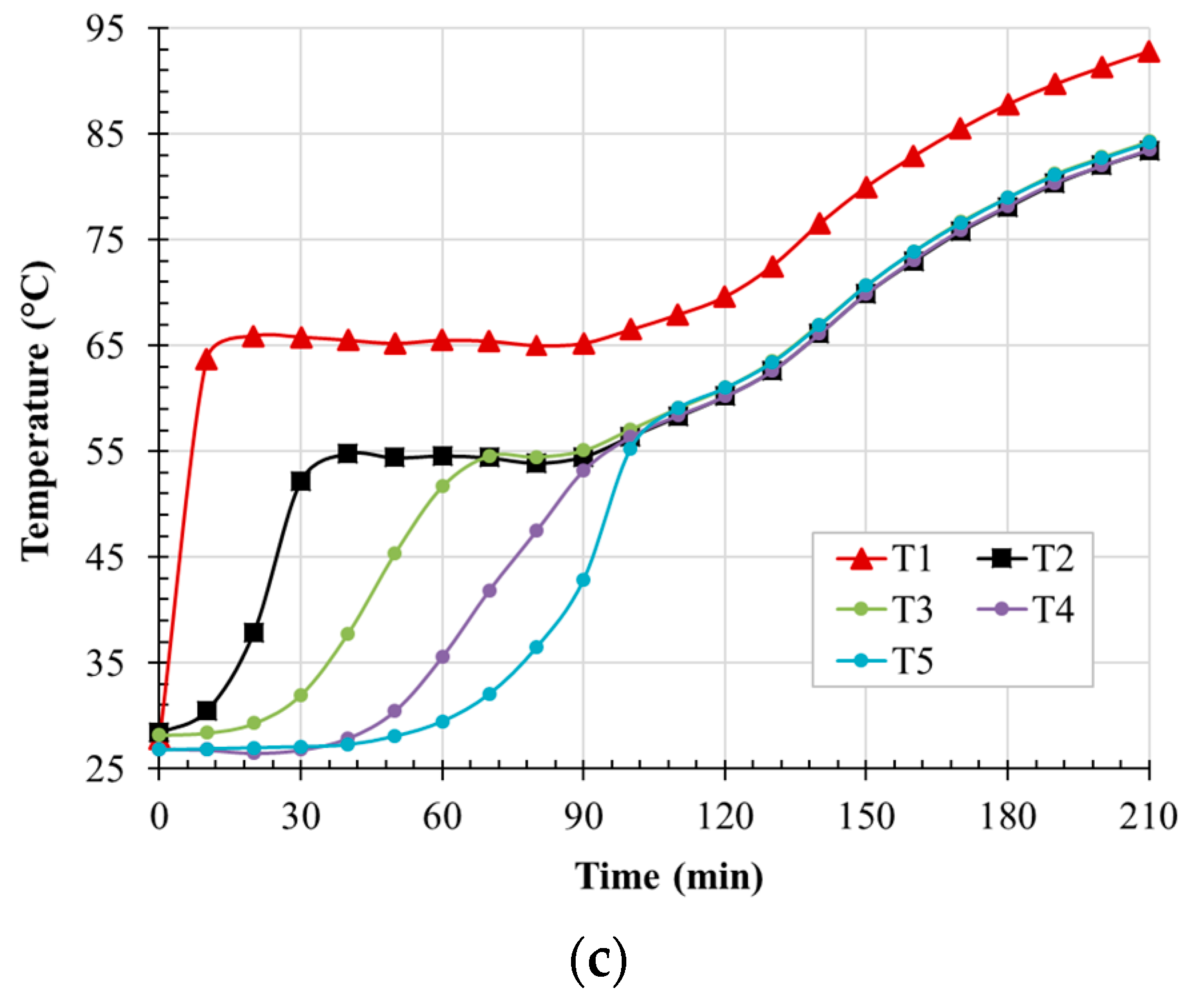
The temperature distribution across heat sink B is shown in Figure 11. It is clearly shown that the heat sink temperature at front (T1) increases rapidly as compared to the temperature at middle and rear due to the PCM low thermal conductivity which causes the heat transfer at lower rate from front to rear of the heat sink. Also, by the end of the melting process, the PCM temperatures are same for all locations as shown for 1.5 and 2.0 W. In addition, the temperature differences after the melting process between the heat sink and the PCM temperatures at the other locations are 8.2 °C and 9.4 °C for 1.5 W and 2.0 W, respectively.
3.5. Effect of Using Two PCMs on Heat Sink Temperature
The effect of using two PCMs with different melting temperatures has been investigated in this section using heat sink C. The PCM with a lower melting temperature is placed in the cavity nearer to the heat source. Figure 12 shows the heat sink surface temperature versus time for two cases (a) single PCM and (b) two PCMs for the same amount of PCM for 1.0 W and 2.0 W power ratings. For the 1.0 W power rating, the heat sink temperature for RT50 and RT50–RT55 has the same thermal regulation temperature (61.4 °C) whereas the heat sink temperature is 65 °C when using RT55.
For the 2.0 W power rating, two thermal regulation temperatures are observed at 70.1 °C and 83.0 °C in the case of RT50–RT55. The second thermal regulation period temperature is higher than the RT55 thermal regulation temperature. This can be referred to the low thermal conductivity of the PCM, and the first PCM increases the heat sink temperature after the complete melting. Also, it can be observed that during the 6 h of heat charging, the maximum heat sink temperature was reduced when using the two PCM arrangement and its maximum for RT50, RT55 and RT50–RT55 is 103.6 °C, 99.4 °C and 93.3 °C, respectively.
In order to verify the two thermal regulation periods for the two PCMs system, lower melting temperature PCMs have been selected: RT47, RT50 and RT47–RT50 as shown in Figure 13. For the 1.0 W power rating, RT47 is more effective in thermal regulation than RT50 and RT47–RT50 during the 6 h of heat charging. However, for the 2.0 W power rating, RT47–RT50 is able to slightly reduce the heat sink maximum temperature for the charging period between 160 and 320 min.
Exchanging the arrangement of the two PCMs to examine their effect has been investigated. Therefore, the PCM with a higher melting temperature is placed in the cavity nearer to the heat source. For the 1.5 W power rating, the heat sink temperature for RT47–RT58 is considerably lower than that of RT58–RT47 during the thermal regulation period (between 20 min and 140 min) as shown in Figure 14. After 140 min, the heat sink temperature is lower for the case of RT58–RT47. For the 2.0 W power rating, RT58–RT47 has a longer thermal regulation period in the time duration between 84 and 240 min of charging, and no change in the heat sink temperature is observed by the end of the operation.
4. Conclusions
An experimental investigation of a PCM heat sink for electronic thermal regulation applications has been explored. The effect of the PCM heat sink has been compared to a non-PCM heat sink. Also, the variation of PCM thickness, melting temperature and the two PCM concept have been studied in this work for power ratings ranging between 1.0 W to 2.0 W. The variations in the heat sink temperature and the PCM melting profile with time have been used to analyze the system performance. The following is concluded from this work:
- Two PCM techniques with arrangement of RT50–RT55 increases the thermal regulation period by 110 min and 130 min as compared to RT50 and RT55, respectively. Using RT50–RT55, the heat sink temperature at the end of the operation is reduced by 10.3 °C and 6.1 °C as compared to RT50 and RT55, respectively, for 2.0 W.
- Two PCMs with the arrangement of RT58-RT47 reduces slightly the maximum temperature as compared to RT47–RT58.
- As PCM thickness increases from 30 to 60 mm, the thermal regulation period increases by 50 min and 35 min for 1.5 W and 2.0 W power ratings, respectively. As the PCM melting temperature increases from 47 (RT47) to 58 °C (RT58), the thermal regulation period increases from 30 to 70 min for 2.0 W. However, the heat sink temperature also increases from 63 to 74 °C.
- The thermal regulation period significantly decreases as power rating increases from 1 to 2 W. Also, the heat sink temperature increases by 29.5 °C with an increase in power rating.
Author Contributions
I.A.S. conceived, designed and performed the experiments; I.A.S. and S.K. analyzed the data; I.A.S. wrote the paper, S.K., T.M. and S.S. reviewed the paper and supervised I.A.S. research work.
Funding
Idris Al Siyabi’s PhD is funded by the Ministry of Higher Education of the Sultanate of Oman as part of the national program of postgraduate scholarships.
Conflicts of Interest
The authors declare no conflict of interest.
References
- Etemoglu, A.B. A brief survey and economical analysis of air cooling for electronic equipments. Int. Commun. Heat Mass Transf. 2007, 34, 103–113. [Google Scholar] [CrossRef]
- Yeh, L.T. Review of heat transfer technologies in electronic equipment. J. Electron. Packag. 1995, 117, 333–339. [Google Scholar] [CrossRef]
- Alawadhi, E.M.; Amon, C.H. PCM thermal control unit for portable electronic devices: Experimental and numerical studies. IEEE Trans. Compon. Packag. Technol. 2003, 26, 116–125. [Google Scholar] [CrossRef]
- Faraji, M.; El Qarnia, H. Passive Cooling of Protruding Electronic Components by Latent Heat of Fusion Storage. ASME J. Electron. Packag. 2009, 131, 021011. [Google Scholar] [CrossRef]
- Jaworski, M. Thermal performance of heat spreader for electronics cooling with incorporated phase change material. Appl. Therm. Eng. 2012, 35, 212–219. [Google Scholar] [CrossRef]
- Kandlikar, S.G.; Ii, C.N.H. Liquid Cooled Cold Plates for Industrial High- Power Electronic Devices—Thermal Design and Manufacturing Considerations Liquid Cooled Cold Plates for Industrial High-Power Electronic Devices—Thermal Design and Manufacturing Considerations. Heat Transf. Energy 2011, 30, 918–930. [Google Scholar] [CrossRef]
- Zhu, L.; Boehm, R.F.; Wang, Y.; Halford, C.; Sun, Y. Water immersion cooling of PV cells in a high concentration system. Sol. Energy Mater. Sol. Cells 2011, 95, 538–545. [Google Scholar] [CrossRef]
- Tardy, F.; Sami, S.M. Thermal analysis of heat pipes during thermal storage. Appl. Therm. Eng. 2009, 29, 329–333. [Google Scholar] [CrossRef]
- Vandersande, J.W.; Fleurial, J.-P. Thermal Management of Power Electronics using Thermoelectric Coolers. In Proceedings of the Fifteenth International Conference on Thermoelectrics, Pasadena, CA, USA, 26–39 March 1996; pp. 252–255. [Google Scholar]
- Ohadi, M.; Choo, K.; Dessiatoun, S.; Cetegen, E. Next Generation Microchannel Heat Exchangers; Springer: Berlin, Germany, 2013; ISBN 978-1-4614-0778-2. [Google Scholar]
- Farid, M.M.; Khudhair, A.M.; Razack, S.A.K.; Al-Hallaj, S. A review on phase change energy storage: Materials and applications. Energy Convers. Manag. 2004, 45, 1597–1615. [Google Scholar] [CrossRef]
- Ge, Z.; Li, Y.; Li, D.; Sun, Z.; Jin, Y.; Liu, C.; Li, C.; Leng, G.; Ding, Y. Thermal energy storage: Challenges and the role of particle technology. Particuology 2014, 15, 2–8. [Google Scholar] [CrossRef]
- Ma, T.; Yang, H.; Zhang, Y.; Lu, L.; Wang, X. Using phase change materials in photovoltaic systems for thermal regulation and electrical efficiency improvement: A review and outlook. Renew. Sustain. Energy Rev. 2015, 43, 1273–1284. [Google Scholar] [CrossRef]
- Sharma, A.; Tyagi, V.V.; Chen, C.R.; Buddhi, D. Review on thermal energy storage with phase change materials and applications. Renew. Sustain. Energy Rev. 2009, 13, 318–345. [Google Scholar] [CrossRef]
- Humphries, W.; Griggs, E. A Design Handbook for Phase Change Thermal Control and Energy Storage Devices; NASA Technical Paper; NASA: Buffalo, NY, USA, 1977.
- Hasan, A.; Alnoman, H.; Shah, A. Energy Efficiency Enhancement of Photovoltaics by Phase Change Materials through Thermal Energy Recovery. Energies 2016, 9, 782. [Google Scholar] [CrossRef]
- Hasan, A.; McCormack, S.J.; Huang, M.J.; Norton, B. Energy and cost saving of a photovoltaic-phase change materials (PV-PCM) System through temperature regulation and performance enhancement of photovoltaics. Energies 2014, 7, 1318–1331. [Google Scholar] [CrossRef]
- Krishnan, S.; Garimella, S.V. Thermal Management of Transient Power Spikes in Electronics—Phase Change Energy Storage or Copper Heat Sinks? J. Electron. Packag. 2004, 126, 308. [Google Scholar] [CrossRef]
- Tan, F.L.; Tso, C.P. Cooling of mobile electronic devices using phase change materials. Appl. Therm. Eng. 2004, 24, 159–169. [Google Scholar] [CrossRef]
- Hodes, M.; Weinstein, R.D.; Pence, S.J.; Piccini, J.M.; Manzione, L.; Chen, C. Transient Thermal Management of a Handset Using Phase Change Material (PCM). J. Electron. Packag. 2002, 124, 419. [Google Scholar] [CrossRef]
- Lafdi, K.; Mesalhy, O.; Elgafy, A. Merits of Employing Foam Encapsulated Phase Change Materials for Pulsed Power Electronics Cooling Applications. J. Electron. Packag. 2008, 130, 021004. [Google Scholar] [CrossRef]
- Saha, S.K. Cooling of Electronics with Phase Change Materials under Constant Power and Cyclic Heat Loads. AIP Conf. Proc. 2009, 31. [Google Scholar] [CrossRef]
- Kandasamy, R.; Wang, X.-Q.; Mujumdar, A.S. Application of phase change materials in thermal management of electronics. Appl. Therm. Eng. 2007, 27, 2822–2832. [Google Scholar] [CrossRef]
- Weinstein, R.D.; Kopec, T.C.; Fleischer, A.S.; D’Addio, E.; Bessel, C.A. The Experimental Exploration of Embedding Phase Change Materials With Graphite Nanofibers for the Thermal Management of Electronics. J. Heat Transf. 2008, 130, 042405. [Google Scholar] [CrossRef]
- Khanna, S.; Reddy, K.S.; Mallick, T.K. Climatic behaviour of solar photovoltaic integrated with phase change material. Energy Convers. Manag. 2018, 166, 590–601. [Google Scholar] [CrossRef]
- Fan, L.W.; Xiao, Y.Q.; Zeng, Y.; Fang, X.; Wang, X.; Xu, X.; Yu, Z.T.; Hong, R.H.; Hu, Y.C.; Cen, K.F. Effects of melting temperature and the presence of internal fins on the performance of a phase change material (PCM)-based heat sink. Int. J. Therm. Sci. 2013, 70, 114–126. [Google Scholar] [CrossRef]
- Thapa, S.; Chukwu, S.; Khaliq, A.; Weiss, L. Fabrication and analysis of small-scale thermal energy storage with conductivity enhancement. Energy Convers. Manag. 2014, 79, 161–170. [Google Scholar] [CrossRef]
- Baby, R.; Balaji, C. Experimental investigations on thermal performance enhancement and effect of orientation on porous matrix filled PCM based heat sink. Int. Commun. Heat Mass Transf. 2013, 46, 27–30. [Google Scholar] [CrossRef]
- Huang, M.J. The effect of using two PCMs on the thermal regulation performance of BIPV systems. Sol. Energy Mater. Sol. Cells 2011, 95, 957–963. [Google Scholar] [CrossRef]
- Jegadheeswaran, S.; Pohekar, S.D. Performance enhancement in latent heat thermal storage system: A review. Renew. Sustain. Energy Rev. 2009, 13, 2225–2244. [Google Scholar] [CrossRef]
- Wang, X.Q.; Mujumdar, A.S.; Yap, C. Effect of orientation for phase change material (PCM)-based heat sinks for transient thermal management of electric components. Int. Commun. Heat Mass Transf. 2007, 34, 801–808. [Google Scholar] [CrossRef]
- Khanna, S.; Reddy, K.S.; Mallick, T.K. Performance analysis of tilted photovoltaic system integrated with phase change material under varying operating conditions. Energy 2017, 133, 887–899. [Google Scholar] [CrossRef] [Green Version]
- Avci, M.; Yazici, M.Y. An experimental study on effect of inclination angle on the performance of a PCM-based flat-type heat sink. Appl. Therm. Eng. 2018, 131, 806–814. [Google Scholar] [CrossRef]
- Poran, S.; Ahmed, D.H. Effect of cavity shape and heat source/sink orientation on PCM melting. J. Therm. Energy Syst. 2018, 3, 1–22. [Google Scholar]
- Khanna, S.; Reddy, K.S.; Mallick, T.K. Optimization of solar photovoltaic system integrated with phase change material. Sol. Energy 2018, 163, 591–599. [Google Scholar] [CrossRef]
- Khanna, S.; Reddy, K.S.; Mallick, T.K. Optimization of finned solar photovoltaic phase change material (finned pv pcm) system. Int. J. Therm. Sci. 2018, 130, 313–322. [Google Scholar] [CrossRef]
- Kandasamy, R.; Wang, X.Q.; Mujumdar, A.S. Transient cooling of electronics using phase change material (PCM)-based heat sinks. Appl. Therm. Eng. 2008, 28, 1047–1057. [Google Scholar] [CrossRef]
- Fok, S.C.; Shen, W.; Tan, F.L. Cooling of portable hand-held electronic devices using phase change materials in finned heat sinks. Int. J. Therm. Sci. 2010, 49, 109–117. [Google Scholar] [CrossRef]
- Mahmoud, S.; Tang, A.; Toh, C.; AL-Dadah, R.; Soo, S.L. Experimental investigation of inserts configurations and PCM type on the thermal performance of PCM based heat sinks. Appl. Energy 2013, 112, 1349–1356. [Google Scholar] [CrossRef]
- Huang, M.J.; Eames, P.C.; Norton, B. Phase change materials for limiting temperature rise in building integrated photovoltaics. Sol. Energy 2006, 80, 1121–1130. [Google Scholar] [CrossRef]
- Wang, X.Q.; Yap, C.; Mujumdar, A.S. A parametric study of phase change material (PCM)-based heat sinks. Int. J. Therm. Sci. 2008, 47, 1055–1068. [Google Scholar] [CrossRef]
- Arshad, A.; Ali, H.M.; Ali, M.; Manzoor, S. Thermal performance of phase change material (PCM) based pin-finned heat sinks for electronics devices: Effect of pin thickness and PCM volume fraction. Appl. Therm. Eng. 2017, 112, 143–155. [Google Scholar] [CrossRef]
- Saha, S.K.; Srinivasan, K.; Dutta, P. Studies on optimum distribution of fins in heat sinks filled with phase change materials. J. Heat Transf. 2008, 130, 034505. [Google Scholar] [CrossRef]
- Tomizawa, Y.; Sasaki, K.; Kuroda, A.; Takeda, R.; Kaito, Y. Experimental and numerical study on phase change material (PCM) for thermal management of mobile devices. Appl. Therm. Eng. 2016, 98, 320–329. [Google Scholar] [CrossRef] [Green Version]
- Emam, M.; Ahmed, M. Cooling concentrator photovoltaic systems using various configurations of phase-change material heat sinks. Energy Convers. Manag. 2018, 158, 298–314. [Google Scholar] [CrossRef]
- Shaikh, S.; Lafdi, K. Effect of multiple phase change materials (PCMs) slab configurations on thermal energy storage. Energy Convers. Manag. 2006, 47, 2103–2117. [Google Scholar] [CrossRef]
- Soares, N.; Gaspar, A.R.; Santos, P.; Costa, J.J. Experimental study of the heat transfer through a vertical stack of rectangular cavities filled with phase change materials. Appl. Energy 2015, 142, 192–205. [Google Scholar] [CrossRef]
Figure 1.
Schematic of the (a) heat sink A&B, (b) heat sink C and (c) experimental setup. PCM: phase change material.
Figure 1.
Schematic of the (a) heat sink A&B, (b) heat sink C and (c) experimental setup. PCM: phase change material.

Figure 2.
Thermocouple positions and dimensions of heat sinks, (a) A; (b) B and (c) C.

Figure 3.
Comparison between PCM and no PCM heat sink temperatures for three different power ratings.
Figure 3.
Comparison between PCM and no PCM heat sink temperatures for three different power ratings.

Figure 4.
Heat sink surface temperature using RT47 for three different power ratings.

Figure 5.
Images of RT47 melting profile for different power rating and time.

Figure 6.
Temperature distribution across the heat sink A for RT47 at power rating, (a) 1.0 W, (b) 1.5 W and (c) 2.0 W.
Figure 6.
Temperature distribution across the heat sink A for RT47 at power rating, (a) 1.0 W, (b) 1.5 W and (c) 2.0 W.

Figure 7.
Surface temperature for heat sink A at power rating, (a) 1.0 W, (b) 1.5 W and (c) 2.0 W.

Figure 8.
Melting profiles images for various PCMs at different time and 1.5 W heat input.

Figure 9.
Heat sink surface temperature using RT47 for different thicknesses at power ratings (a) 1.0 W, (b) 1.5 W and (c) 2.0 W.
Figure 9.
Heat sink surface temperature using RT47 for different thicknesses at power ratings (a) 1.0 W, (b) 1.5 W and (c) 2.0 W.

Figure 10.
Heat sink surface temperature of RT58 for different thickness at power ratings (a) 1.0 W, (b) 1.5 W and (c) 2.0 W.
Figure 10.
Heat sink surface temperature of RT58 for different thickness at power ratings (a) 1.0 W, (b) 1.5 W and (c) 2.0 W.

Figure 11.
Temperature distribution across heat sink B for RT47 at power ratings (a) 1.0 W, (b) 1.5 W and (c) 2.0 W.
Figure 11.
Temperature distribution across heat sink B for RT47 at power ratings (a) 1.0 W, (b) 1.5 W and (c) 2.0 W.


Figure 12.
Surface heat sink temperature of one and two PCM heat sinks for different PCMs at power rating of, (a) 1.0 W and (b) 2.0 W.
Figure 12.
Surface heat sink temperature of one and two PCM heat sinks for different PCMs at power rating of, (a) 1.0 W and (b) 2.0 W.

Figure 13.
Heat sink surface temperature of one and two PCM heat sinks at power rating, (a) 1.0 W and (b) 2.0 W.
Figure 13.
Heat sink surface temperature of one and two PCM heat sinks at power rating, (a) 1.0 W and (b) 2.0 W.

Figure 14.
Heat sink surface temperature of heat sink C for different PCMs at power ratings (a) 1.5 W and (b) 2.0 W.
Figure 14.
Heat sink surface temperature of heat sink C for different PCMs at power ratings (a) 1.5 W and (b) 2.0 W.


Table 1.
Heat sink temperature during heat charging.
| PCM Type | Heat Sink Temperature at the Phase Change (°C) | Heat Sink Temperature at the End of Charging (210 min) °C | ||||
|---|---|---|---|---|---|---|
| Power Rating | Power Rating | |||||
| 1.0 W | 1.5 W | 2.0 W | 1.0 W | 1.5 W | 2.0 W | |
| RT47 | 55.2 | 59.0 | 63.0 | 56.8 | 72.3 | 86.3 |
| RT50 | 60.1 | 62.3 | 64.9 | 60.3 | 75.0 | 86.0 |
| RT52 | 59.3 | 63.6 | 67.3 | 59.3 | 74.4 | 87.0 |
| RT55 | 62.0 | 65.0 | 67.4 | 62.0 | 72.3 | 85.3 |
| RT58 | 64.4 | 69.0 | 73.6 | 64.4 | 69.0 | 84.5 |
© 2018 by the authors. Licensee MDPI, Basel, Switzerland. This article is an open access article distributed under the terms and conditions of the Creative Commons Attribution (CC BY) license (http://creativecommons.org/licenses/by/4.0/).
Share and Cite
MDPI and ACS Style
Al Siyabi, I.; Khanna, S.; Mallick, T.; Sundaram, S. Multiple Phase Change Material (PCM) Configuration for PCM-Based Heat Sinks—An Experimental Study. Energies 2018, 11, 1629. https://doi.org/10.3390/en11071629
AMA Style
Al Siyabi I, Khanna S, Mallick T, Sundaram S. Multiple Phase Change Material (PCM) Configuration for PCM-Based Heat Sinks—An Experimental Study. Energies. 2018; 11(7):1629. https://doi.org/10.3390/en11071629
Chicago/Turabian StyleAl Siyabi, Idris, Sourav Khanna, Tapas Mallick, and Senthilarasu Sundaram. 2018. "Multiple Phase Change Material (PCM) Configuration for PCM-Based Heat Sinks—An Experimental Study" Energies 11, no. 7: 1629. https://doi.org/10.3390/en11071629
Note that from the first issue of 2016, this journal uses article numbers instead of page numbers. See further details here.