Article

Numerical Analysis of Heat and Gas Transfer Characteristics during Heat Injection Processes Based on a Thermo-Hydro-Mechanical Model

1
State Key Laboratory of Eco-hydraulics in Northwest Arid Region, Xi’an University of Technology, Xi’an 710048, China
2
Institute of Geotechnical Engineering, Shaanxi Provincial Key Laboratory of Loess Mechanics and Engineering, Xi’an University of Technology, Xi’an 710048, China
3
School of Civil Engineering, Henan Polytechnic University, Jiaozuo 454003, China
4
State Key Laboratory for Geomechanics and Deep Underground Engineering, China University of Mining and Technology, Xuzhou 221116, China
*
Author to whom correspondence should be addressed.
Energies 2018, 11(7), 1722; https://doi.org/10.3390/en11071722
Submission received: 2 May 2018 / Revised: 16 June 2018 / Accepted: 20 June 2018 / Published: 1 July 2018
(This article belongs to the Special Issue Geothermal Energy: Utilization and Technology 2018)

Abstract

:
Heat injection is an important artificial technique, which can significantly enhance the extraction efficiency of coal seam gas (CSG) and reduce the outburst risk caused by CSG. Although heat injection has been comprehensively investigated, the effect of temperature on the coal–gas interactions in CSG extraction is still not clear. In this study, a thermo-hydro-mechanical model was developed considering the expansion of coal mass and the change of adsorption capacity induced by heat injection. Subsequently, the reliability of the model was verified through a comparison with other theoretical models and field data. Finally, a numerical simulation and parameter analysis of the heat injection process were performed and compared with the traditional gas extraction method. The simulation results show that heat injection can significantly increase the gas production rate and cumulative gas production through the gas desorption and the permeability increase. The gas content in the coal seam dramatically decreases in the vicinity of the production and heat injection wells under the condition of heat injection, which greatly accelerates the gas drainage. The coal deformation caused by thermal-induced gas desorption has a more dominant effect on the porosity than other factors, i.e., pore pressure, thermal strain and compressive strain.

1. Introduction

Coal seam gas (CSG) is recognized as a fuel and chemical raw material for clean energy recovery. Simultaneously, it is also a hazardous gas in coal mines that can cause explosions, worker suffocation, and gas outbursts. Gas extraction technology is adopted in coal mines to reduce the gas pressure and eliminate the risk caused by coal mine gas. Underground wells and ground drilling are usually used in the pre-extraction process, and underground drainage is the main system for realizing actual reservoir conditions [1,2,3,4,5,6]. However, various coal seams in the southwest of China are low-permeability coal seams [7], and methane stored in these seams cannot be effectively extracted, which leads to difficulty in methane extraction during disaster control [8,9,10].
The permeability of a coal seam is related to the interactions between coal and gas, such as gas adsorption, effective stress and temperature change, and other factors caused by the pore/crack evolution of coal [11,12,13]. Numerous models have been developed to study the evolution of permeability of coal during the gas extraction process, including Warren and Root [14], Robertson and Christiansen [15], Cui and Bustin [16], Shi et al. [17], etc., where the coupled effect of effective stress, reservoir pressure and adsorption deformation on permeability are considered. From the view of effective strain, Liu et al. [18] studied the isotropic changes in coal permeability and used an index, i.e., modulus reduction ratio, to represent the anisotropy in permeability and deformability based on the relationship between volumetric strain and permeability. The experimental results of gas adsorption show that temperature has an important effect on the methane adsorption capacity of coal [19]. Therefore, scholars also focused on the influence of temperature on the gas seepage behavior in coal seam extraction process. For example, a multi-physical field model of porous media considering solid deformation, fluid flow, and heat transfer was discussed by Tong et al. [20]. Based on the work of Liu et al. [18], Xia et al. [21] investigated the complex interaction between the gas transport and energy transport in porous coal media and proposed a coal spontaneous combustion model of the gas, air-mixed flow, and energy transfer.
Improving the quality of gas drainage is an important objective of scientific researchers in coal mining. Various technological methods are adopted to increase the permeability and achieve efficient gas extraction. For example, the hydraulic fracturing technology, carbon dioxide flooding, thermal stimulation, and other engineering technologies have been successfully applied to enhance the extraction of CBM [22,23,24,25,26,27]. Thermal stimulation techniques have received tremendous attention in recent years because of their superiority [28,29,30,31,32,33]. The principle of thermal stimulation is to heat the coal seam by injecting heated gas or heated water or to adopt the electromagnetic technology to heat the coal seam, and then to achieve efficient gas extraction from the production well [19,34]. It can effectively increase the recovery rate by increasing the reservoir temperature. When the temperature rises, it results in gas desorption from the coal mass.
Some thermal stimulation methods have been proposed and applied in engineering practices. For example, cobalt ferrite nanoparticles could be used as magnetic feed antennas to enhance the magnetic field strength and enhance oil recovery [35]. Moreover, hot water injection is also adopted to increase the gas extraction rate. Compared with traditional production, this heat treatment can significantly improve the recovery rate [36]. High-temperature gas injection is also adopted to achieve enhanced CBM recovery. The effect of high-temperature gas injection is normally better than hot water injection because water may hinder the flow of the gas. For example, high-temperature nitrogen injection can accelerate the rate of methane drainage [37]. Besides N2 injection, CO2 injection is also an effective method to develop the recovery rate [38]. In addition, microwave and radio frequency energy can also be used to increase the shale gas recovery rate by increasing the shale temperature [39,40]. Temperature causes complex interactions between coal and gas, including gas adsorption and pore structure change. On the aspect of experiments, Yin et al. [41] conducted triaxial compression tests of coal samples under different temperature conditions and examined the effect of temperature on the deformation and geo-mechanical characteristics of gas-containing coal. The experimental results showed that temperature was an important physical parameter affecting the adsorption characteristics of coal. Wang et al. [27] studied the effect of pre-injection of nitrogen on coal structure and permeability through experimental and numerical simulations.
However, fewer studies have been conducted on gas extraction with heat injection using a thermo-hydro-mechanical model [40,42]. The effect of temperature on the coal–gas interactions in coal seam gas (CSG) extraction for heat injection is still not clear. In this study, a thermo-hydro-mechanical model was developed to study the coal-gas interactions during heat injection. The coal mass expands and its adsorption capacity decreases with the increase in temperature. These factors are embodied in the expression of permeability based on the concept of effective strain. In addition, non-Darcy effect and Klinkenberg effect of the fluid are also considered in the model. In previous thermo-hydro-mechanical models [40,42], non-Darcy effect and Klinkenberg effect of the fluid were rarely considered, which may cause underestimates in the analyses of heat and gas transfer characteristics during heat injection process. After validating the model with other models and field data, numerical simulations were conducted to investigate the effects of temperature on gas extraction. Finally, evolutions of the permeability, gas content, and gas production with and without heating injection were compared. The effect of heat injection on coal seam gas recovery was analyzed quantitatively.

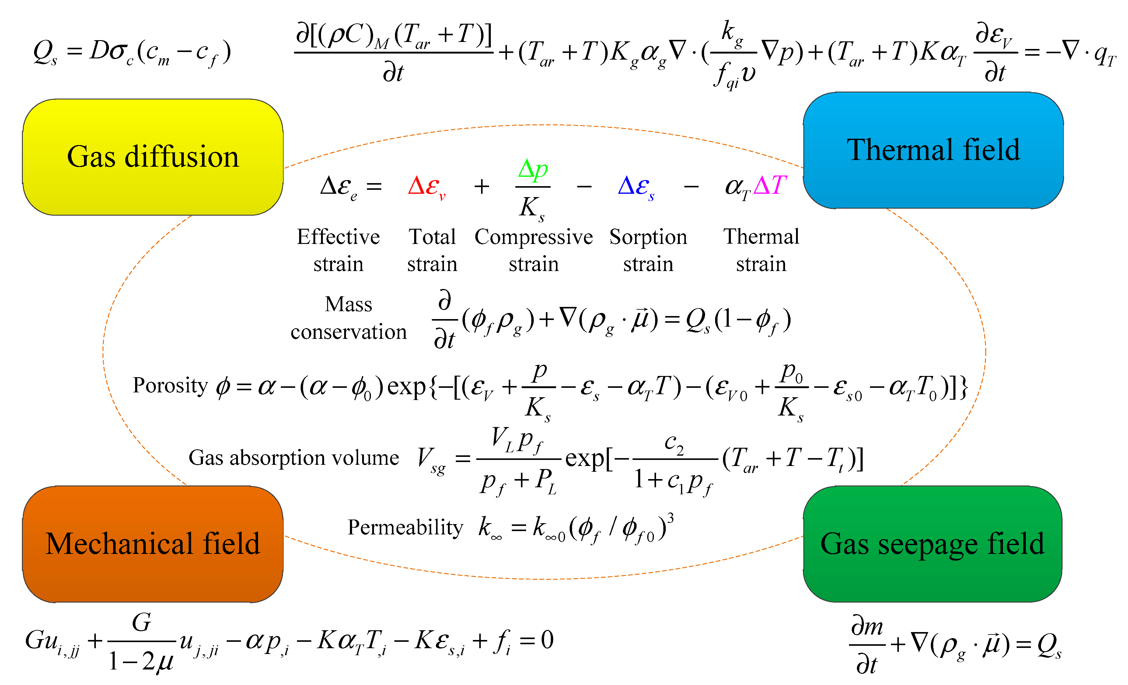
2. Governing Equations of Model

The gas transport occurs in three stages: flow in the fractures, gas diffusion and sorption in the matrix. The governing equations involving these physical processes are given in this section.

2.1. Gas Flow in Fractures

A non-Darcy flow is usually adopted in CSG extraction, and it can be expressed as [43]:
p f = υ k g μ + β ρ g μ | μ |
where μ is the velocity (m/s), ρ g is the density (kg/m3), υ is the dynamic viscosity (Pa⋅s), is the non-Darcy coefficient, β = 1.75 150 k g ϕ f 3 , ϕ f is the porosity, and k g is the permeability (m2).
The gas velocity can be expressed as:
μ = k g ( 1 + k g υ β ρ g | μ | ) υ p f = k g f q i υ p f
where f q i = 1 + k g υ β ρ g | μ | is the Forchheimer number.
For porous media, the flow equilibrium equation can be expressed as:
t ( ϕ f ρ g ) + ( ρ g μ ) = Q s ( 1 ϕ f )
where Q s is the gas source (kg⋅m−3⋅s−1), and mass content m is calculated as [44]:
m = ρ g ϕ f + ρ g a ρ c V s g
where m is the gas mass content (kg/m3), ρ g a is the gas density at standard temperature and pressure (STP) (kg/m3), ρ c is the coal density (kg/m3), and V s g is the content of the absorbed gas (m3⋅kg−1).
The gas absorption volume can be expressed as [45,46]:
V s g = V L p f p f + P L exp [ c 2 1 + c 1 p f ( T a r + T T t ) ]
where V L and p L are the Langmuir volume constant (m3⋅kg−1) and pressure constant (Pa) at the temperature T t , T a r is the absolute reference temperature (K), T t is the reference temperature (K), c 1 and c 2 are the pressure coefficient (Pa−1) and temperature coefficient (K−1).
The sorption-induced volumetric shrinkage strain ε s is assumed as:
ε s = α s g V s g
where V s g is the content of the absorbed gas (m3⋅kg−1) and α s g is the sorption-induced strain coefficient (kg⋅m−3).
The ideal gas law can be expressed as:
ρ g = M g R ( T a r + T ) p
where ρ g is the gas density (m3⋅kg−1), M g is the molecular weight of the gas (kg⋅mol−1), T is the gas temperature (K), and p a is the standard atmospheric pressure (MPa).
Therefore, the gas flow equation can be rewritten as:
ρ g a p a ( ϕ f p f ) t + ( k g υ ρ g f q i p f ) = Q s ( 1 ϕ f )

2.2. Gas Diffusion Process

In the gas diffusion process, the source term can be written as:
Q s = D σ c ( c m c f )
τ = 1 σ c D
where Q s is the exchange between the matrix and the fractures (kg·m−3·s−1), D is the gas diffusion coefficient (m2/s), c m is the gas concentration in the matrix (kg/m3), c f is the gas concentration in the fractures (kg/m3), τ is the sorption time (s), and σ c is the shape factor of coal matrix (m−2).
The gas concentration in the matrix and fractures can be expressed as:
c m = M c R T p m
c f = M c R T p f
The following equation is introduced to calculate the exchange rate:
d m b d t = 1 τ ( m b m e )
where m e is the equilibrium gas content (kg/m3) at pressure p f .
Then the diffusion equation can be written as:
m t = M c τ R T ( p m p f )
where M c is the molar mass of methane (kg/mol), and τ is the sorption time (s).
Effective permeability k g can be written as [47]:
k g = k ( 1 + b p f )
where k is the intrinsic permeability (m2) and b is a coefficient that increases with the reduction in the permeability according to [48]:
b = α k k 0.36
where α k is the Klinkenberg effect coefficient and α k = 0.251.

2.3. Mechanical Equilibrium Equation

For dual porosity media, the effective stress can be expressed as:
σ e i j = σ i j α p f δ i j
where σ e i j is the effective stress (MPa), σ i j is the total stress (MPa), δ i j is the Kronecker delta tensor, p f is the gas pressure in the fractures (MPa), and α is the effective stress coefficient for the coal fractures.
The strain–displacement relation for coal is expressed as:
ε i j = 1 2 ( u i , j + u j , i )
A Navier-type equation is expressed as:
G u i , j j + G 1 2 μ u j , j i α p f , i K α T T , i K ε s , i + f i = 0
where G is the shear modulus (MPa), μ is the Poisson’s ratio, and f i is the body stress (MPa).

2.4. Coal Permeability

The porosity model of coal seam is expressed as:
Δ ϕ f = 1 K ( β f ϕ f ) ( σ ¯ + p f )
Then the porosity is expressed as:
ϕ f = α ( α ϕ 0 ) exp { 1 K [ ( σ ¯ σ ¯ 0 ) + ( p f p f 0 ) ] }
Then the porosity can be rewritten as:
ϕ f = α ( α ϕ f 0 ) exp { [ ( ε V + p f K s ε s α T T ) ( ε V 0 + p f 0 K s ε s 0 α T T 0 ) ] }
where S = ε V + p f K s ε s , S 0 = ε V 0 + p f 0 K s ε s 0 . p 0 is the initial pressure (MPa), and ϕ 0 is the initial porosity.
The permeability can be expressed as:
k = k 0 ( ϕ f / ϕ f 0 ) 3
The apparent permeability in the fracture system is obtained as:
k g k 0 = k k 0 ( 1 + b p f ) = ( ϕ ϕ 0 ) 3 ( 1 + b p f )

2.5. Energy Evolution

Total heat flux q T is given by:
q T = λ M T + ρ g C g μ ( T a r + T )
where q T is the thermal flux (J⋅s−1⋅m−2), ρ s is the mass density of the gas (kg⋅m−3), Cg is the gas-specific heat constant at constant volume (J⋅kg−1⋅K−1), λ M = ( 1 ϕ f ) λ s + ϕ f λ g , and λ M , λ s , and λ g are the thermal conductivities of coal, the solid components, and the gas components (J⋅s−1⋅m−1⋅K−1).
The thermal balance is obtained as [49]:
[ ( ρ C ) M ( T a r + T ) ] t + ( T a r + T ) K g α g ( k g f q i υ p ) + ( T a r + T ) K α T ε V t = q T
where ( ρ C ) M is the specific heat capacity of the solid, ( ρ C ) M = ϕ f ( ρ g C g ) + ( 1 ϕ f ) ( ρ s C s ) , ρ s is the mass density of the gas (kg⋅m−3), and Cg and Cs are the gas heat constant and solid heat constant at constant volume, respectively (J⋅kg−1⋅K−1), i.e., the specific heat capacity of gas and the specific heat capacity of coal.
The conservation of the mass of the two phases can be written as:
[ ( 1 ϕ f ) ρ s ] t = 0
( ϕ f ρ g ) t = ( ρ g μ )
Considering ( 1 ϕ ) λ s ϕ λ s and λ M ( 1 ϕ f ) λ s λ s yields
( ρ C ) M T t ( T a r + T ) K g α g ( k g f q i υ p f ) + ( T a r + T ) K α T ε V t = λ M 2 T + ρ g a p f T a C g p a ( T a r + T ) k g f q i υ p f T
The fully coupled model can be used to analyze the heat injection process. The cross-coupling variable (porosity and permeability) connects different physical fields. The coupled model with different physics is shown in Figure 1. For the mechanical field, the change of pore pressure induces the coal deformation. The change of porosity and permeability will affect the flow velocity and further affect the distribution of pore pressure in seepage field. At the same time, the change of gas velocity and the coal volume also affect the heat transfer. It can be seen from Figure 1 that the effective strain is composed of 4 different parts. The variables (i.e., body strain, pore pressure, adsorption, temperature) contained in the effective strain exist in different physical fields at the same time, and cannot be solved by a single physical field. The cross-coupling variables connect different physical fields.

3. Model Verification and Establishment

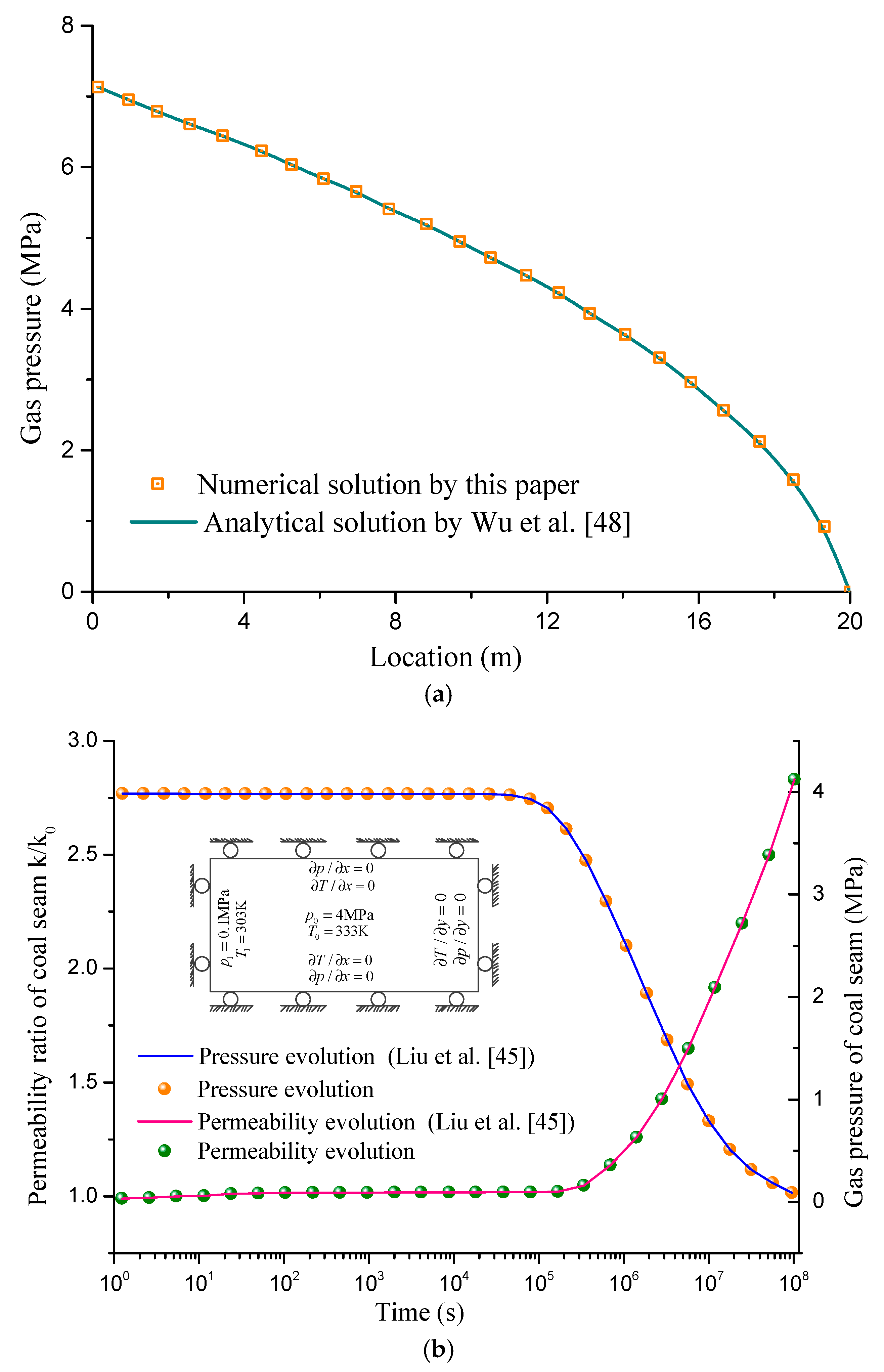
3.1. Analytical Validation

To verify the effectiveness of the aforementioned coupled model in the calculation of CSG extraction, a finite element model is applied, and the simulation results are verified with a simplified analytical solution. A one-dimensional (1D) linear steady gas flow model has a length of 20 m. The gas is injected into the rock with a constant rate of gas at the inlet, and the gas pressure is maintained constant at the outlet. Assuming that the porosity is constant, the gas will eventually reach a steady state. The equation for a 1D linear flow can be reduced from Equation (8) to:
x [ k M g υ R T ( p + b ) p x ] = 0
The boundary conditions are:
{ v g ( x = 0 ) = v 0 p ( x = L ) = p L
At the given boundary conditions, the 1D steady-state analytic solution was given by Wu et al. [48]:
p ( x ) = b + b 2 + p ( L ) 2 + 2 b p ( L ) + 2 v 0 p a ( L x ) υ / k
The calculation parameters are listed in Table 1, and these parameters are also adopted in the analytical solutions. The evolution of the gas pressure calculated by the numerical model and analytical model is compared in Figure 2a, which verifies the validity of the numerical model.

3.2. Numerical Validation

To verify the validity of the model established in this paper, the thermal-hydraulic-mechanical model proposed by Liu et al. [45] is analyzed, which describes the interaction between coal and gas under the effect of the gas pressure, thermal strain, and heat-induced gas desorption. Compared with the porosity model represented by Equation (22), the porosity model of Liu et al. [45] is expressed as:
ϕ ϕ 0 = 1 + α ϕ 0 ( Δ ε V + Δ p K s Δ ε s α T Δ T )
k k 0 = ( ϕ ϕ 0 ) 3 = [ 1 + α ϕ 0 ( Δ ε V + Δ p K s Δ ε s α T Δ T ) ] 3
A 50 m × 100 m rectangular area was considered as the model area, with an initial pressure of 4 MPa. The boundary conditions are shown in Figure 2b. Figure 2b shows that the variation in the gas pressure and permeability in this study agree well with the results obtained using the model of Liu et al.; this further verifies the validity of the proposed model.

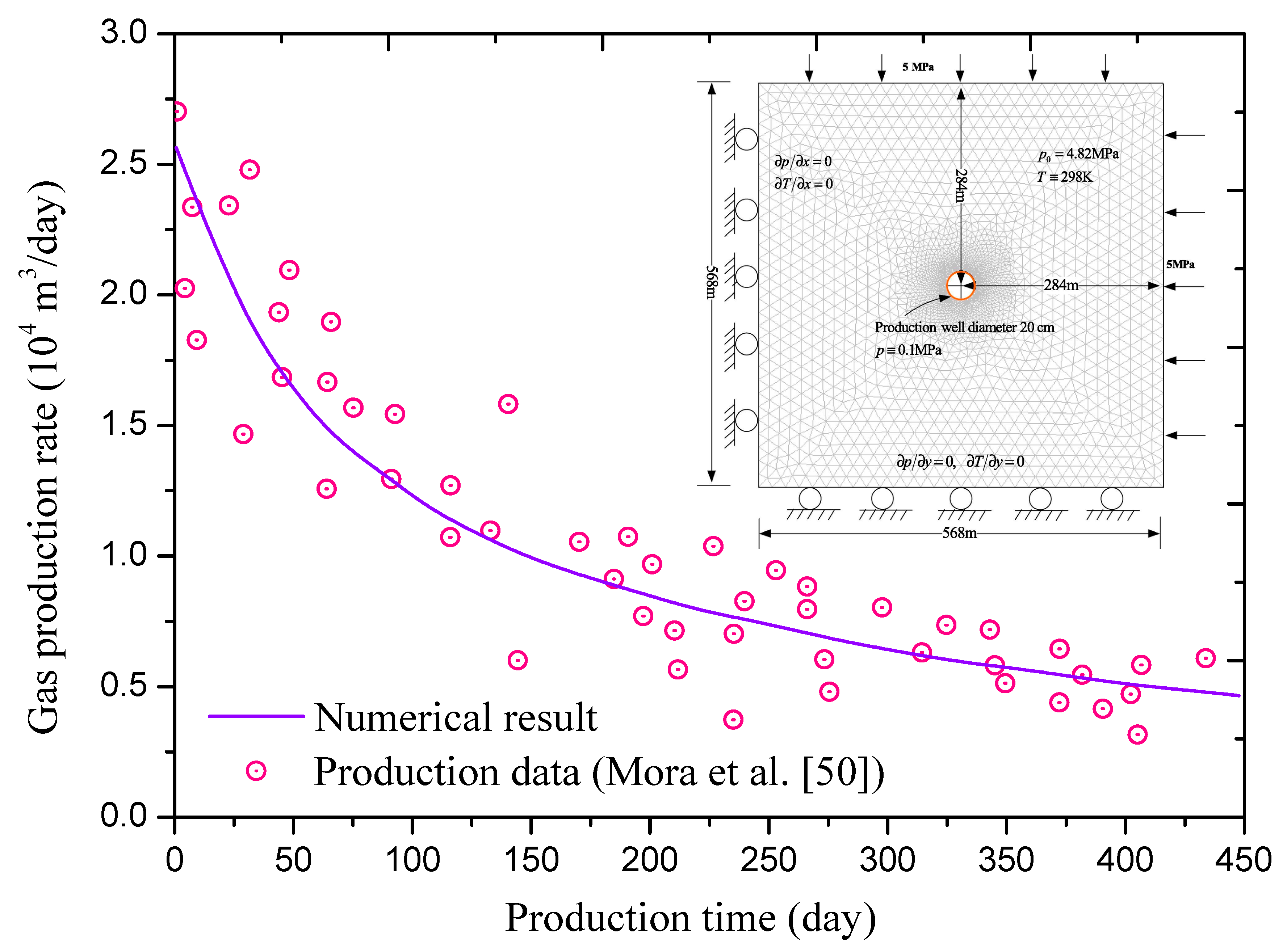
3.3. Verification by Field Data

In order to further verify the model in the simulation of coal seam gas extraction, the calculation model is established based on a simplified form of a gas production process at constant temperature condition in the United States. The CSG recovery area is 3.2 × 10⁵ m2 and the thickness of coal seam is 3.8 m. All the actual parameters used in the calculation are derived from Mora [50], (see in Appendix A). Figure 3 indicates the comparison between the numerical result and the field production data [50], which shows that the proposed model is applicable in simulating and predicting the CSG recovery.

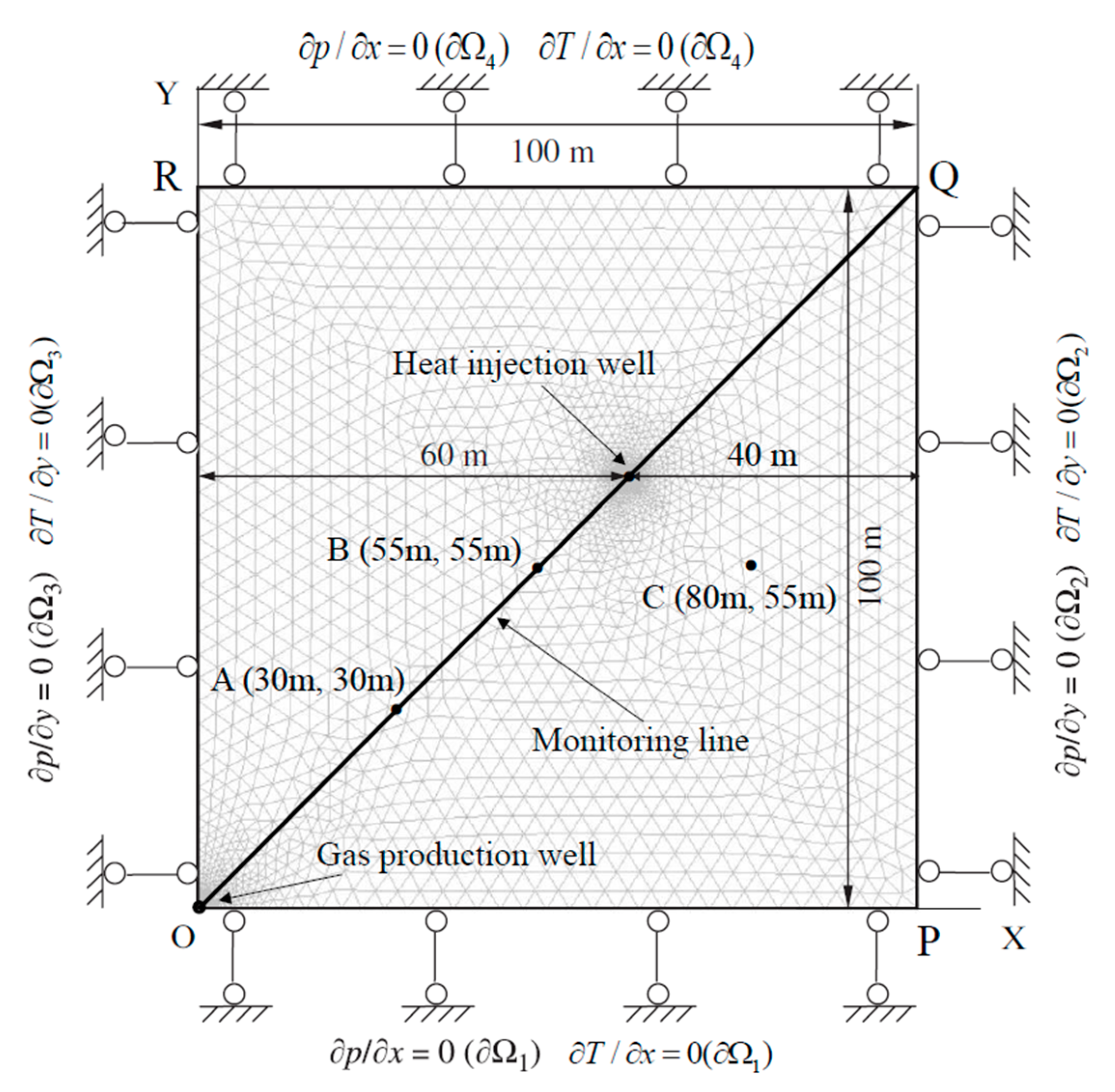
3.4. Model Establishment

To analyze the effect of heat injection on gas extraction, a calculation model (OPQR) was established, as shown in Figure 4. The heat is injected into the well through a hot water recycling system with watertight surface. This system only injects heat into the coal seam without introducing water. For coal deformation, four boundaries are restrained by the normal displacement. For the gas flow, zero fluxes are applied to these boundaries. For the heat transfer, the injection borehole is given a constant temperature of 362.4 K (89.4 °C).
The initial pressure is 3.0 MPa, and the parameters in the calculation are listed in Table 2. The boundary conditions are listed in Table 3. A monitoring line is selected in the diagonal line of the coal mass, and three monitoring points A (30 m, 30 m), B (55 m, 55 m), and C (80 m, 55 m) are used to study the change law of the coal permeability, gas pressure, and production rate.

4. Results and Discussion

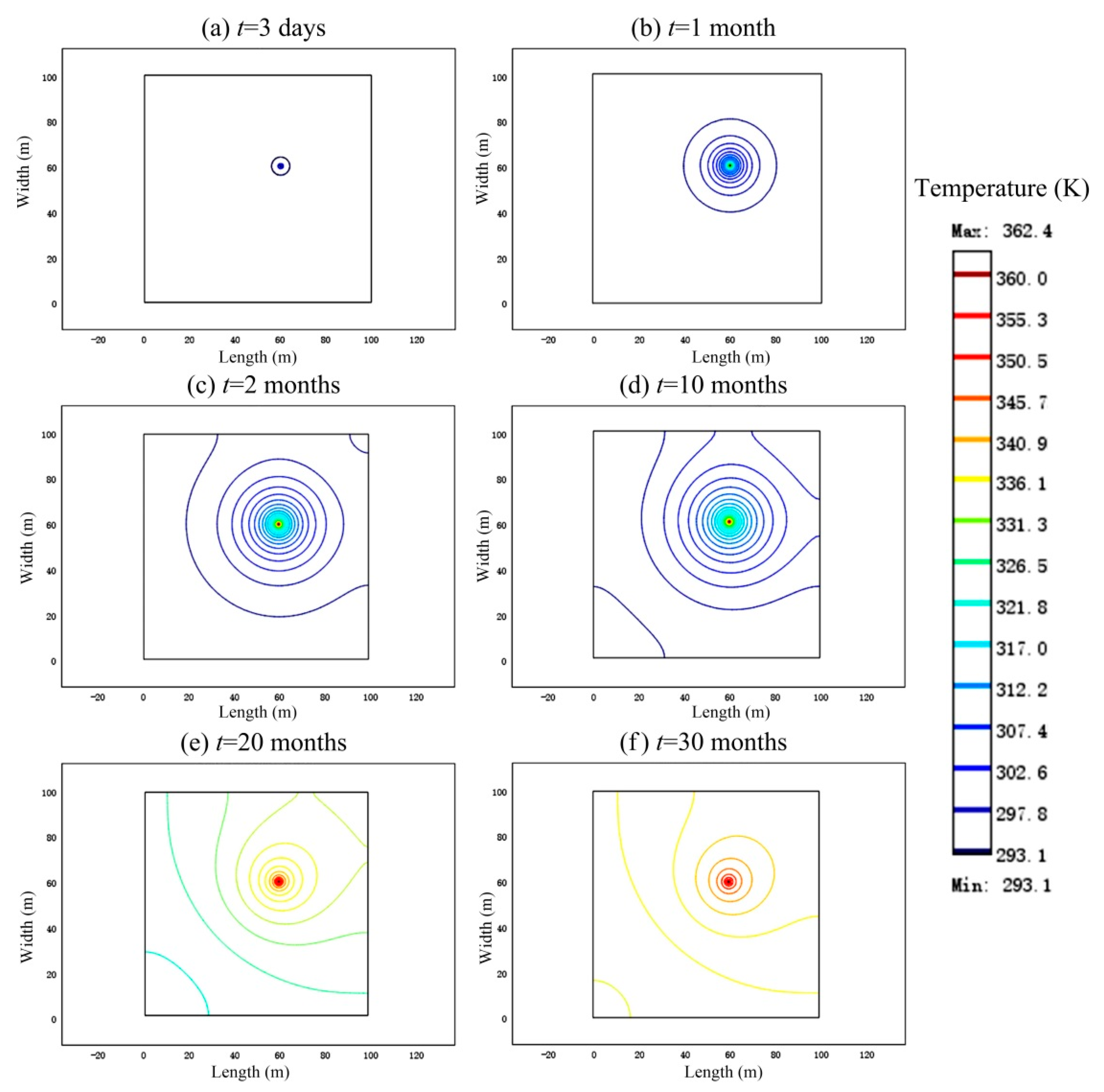
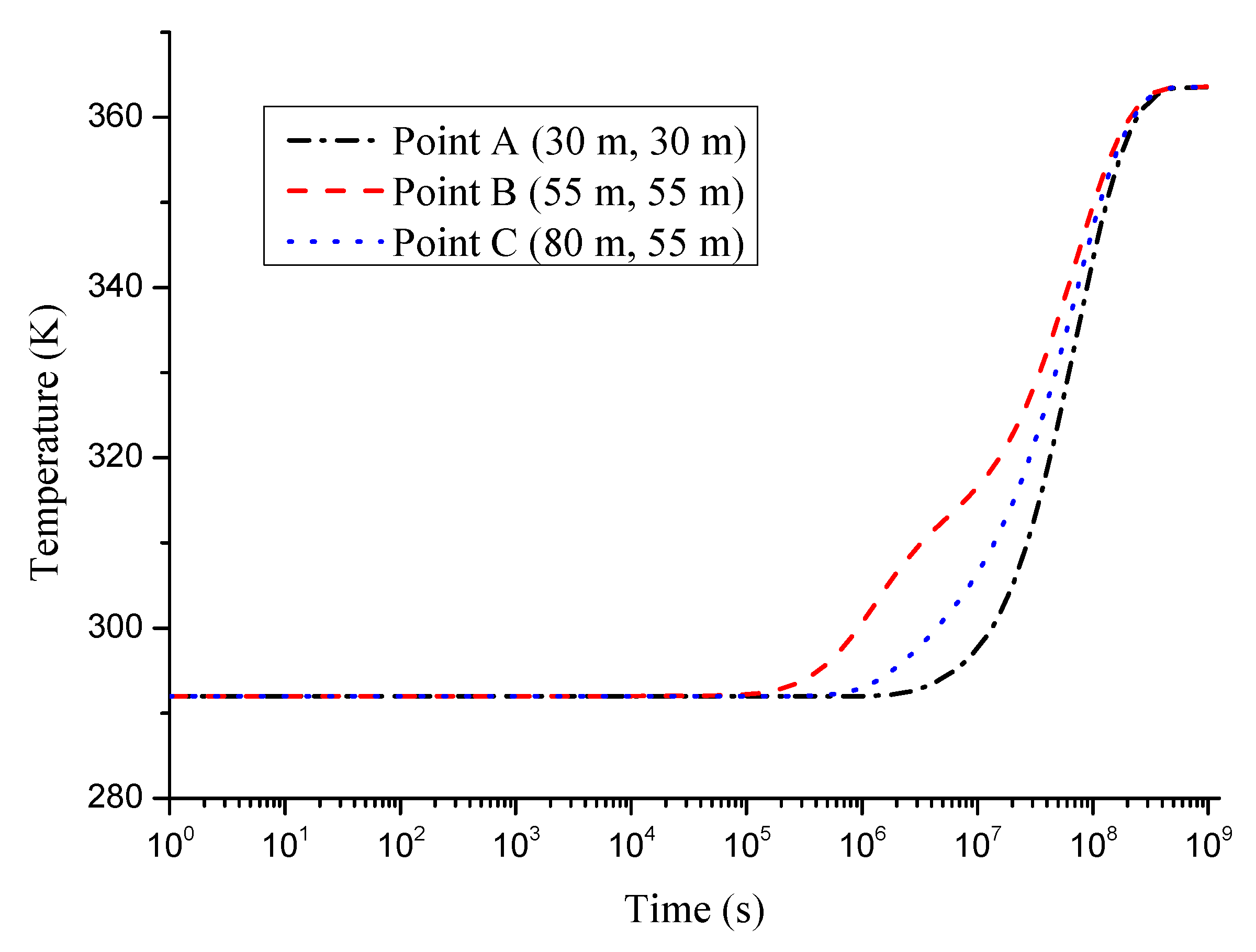
4.1. Thermal Evolution during Heat Injection

The temperature distribution at different production times is shown in Figure 5. Here, it was considered that 1 month was equal to 30 days. The temperature of the coal seam increases with time. Because the injection holes are not located in the center of the model, the temperature contours do not exhibit a central symmetry pattern. The pattern is symmetrical along the axis of the two wells.
Figure 6 depicts the temperature variation of three specific points at different distances from the heat injected well. The initial seam temperature is 293 K. The temperature of point A gradually increases to 300 K at a production time of 9.38 × 10⁵ s (approximately 11 days). The temperature of point B gradually increases to 300 K at a production time of 4.25 × 10⁵ s (approximately 49 days). The temperature of point C gradually increases to 300 K at a production time of 1.34 × 10⁷ s (approximately 155 days). The increase in the temperature also accelerates the flow of the gas, which is beneficial for gas extraction. In the initial short period (105 s), the temperatures of the three points do not show a clear increase. Subsequently, because the distance between point B and the heat injection well is the closest, the temperature increases first at point B, then at C point, and finally at point A. Simultaneously, it can be observed that point B exhibits a fluctuation in the temperature increasing process, without showing a rising trend similar to points A and C. Finally, with the increase in time, the temperatures at the three points eventually attain the same value of 363 K, which is the temperature of the heat injection.

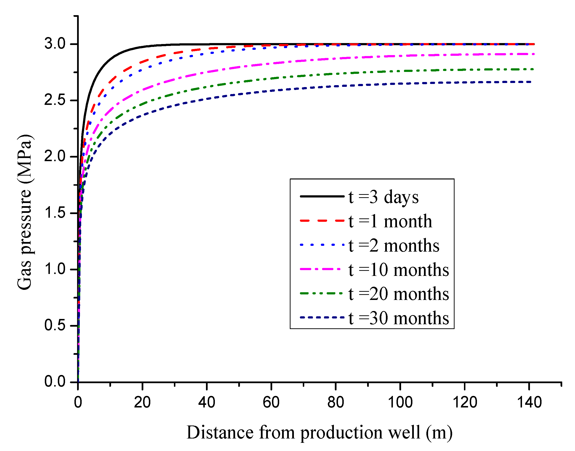
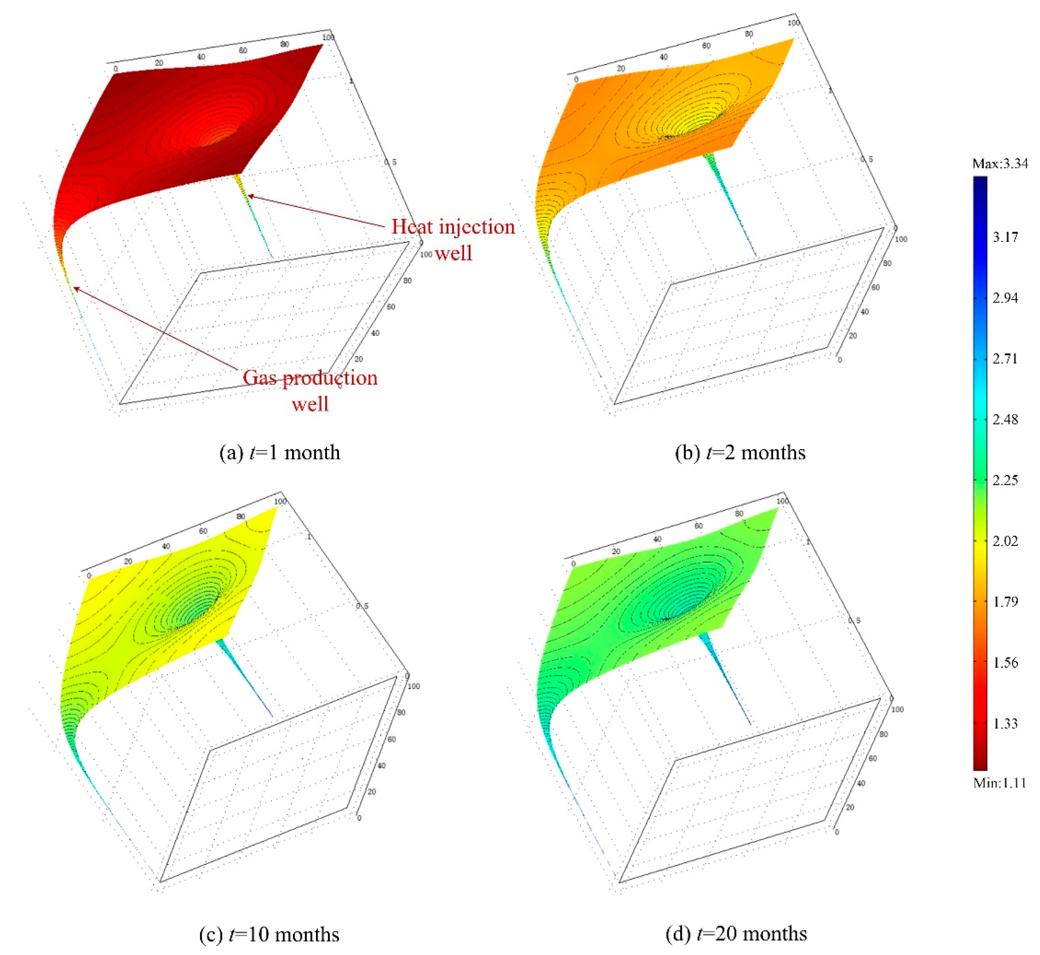
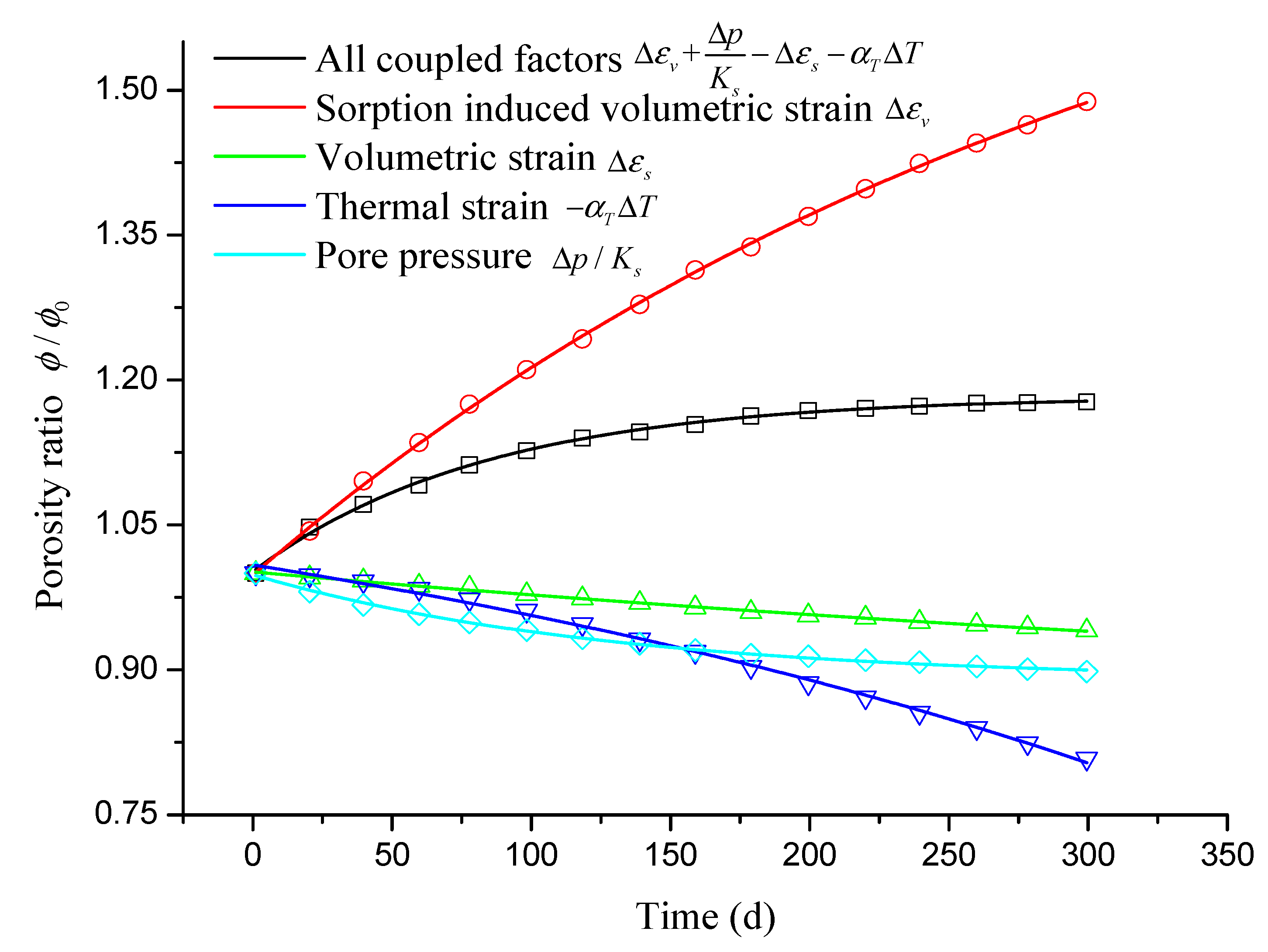
4.2. Gas Pressure Distribution and Permeability Evolution during Heat Injection

The gas pressure evolution characteristic in the coal seam is presented in Figure 7. The gas pressure reduces with the increase in the extraction time. The gas pressure of coal seam is affected by the coupled influence of gas composition, temperature, and porosity. The pore pressure in the coal seam increases with the distance from the well. The velocity of the pressure differential near the borehole is high, and the gas pressure gradually increases with distance from the well.
The evolution law of permeability under the condition of heat injection can be seen from Figure 8. The initial permeability is 1.09 × 10⁻¹⁸ m2 before drilling. Owing to the pressure drop, the permeability around the borehole increases, showing a funnel-shaped trend. The permeability of the boreholes above 20 m is increased by approximately 30% (i.e., k/k0 = 1.3) in two months, compared with the initial condition of gas production. The desorption and drainage are caused by the decrease in the pore pressure in the coal seam. With the development of heat injection, thermal expansion and new adsorption equilibrium of coal occur. In addition, the permeability of coal is increasing. The injection heat can improve the permeability of the coal seam and is conducive for gas drainage. The permeability ratio at point B increased from 1.26 at a production time of 1 month to 2.26 at a production time of 20 months.
The porosity of coal seam is controlled by the volume of the coal matrix blocks, which consists of the effective volumetric strain, compressive strain, adsorption-induced strain, and thermal-induced strain. Figure 9 depicts the variation in the contributions of these components to porosity. A porosity exceeding 1 implies that the porosity is increasing under the effect of this factor. The contributions of the various factors to the process of heat injection are obvious. Once exposed to the atmosphere, the CBM will be discharged into the borehole by the differential pressure. Thus, the gas pressure in the coal seam is reduced. This pressure drop leads to a change in the effective strain and coal mass desorption, which in turn change the porosity [37]. In the early stage of gas drainage, thermal-induced strain has little effect on the porosity. With time, the temperature of point A increases gradually. Although the temperature of coal typically increases, the deformation is restrained under the restriction of an external boundary, so that the compressive stress slightly reduces the porosity of coal. When the strain caused by adsorption is considered, the porosity of coal increases rapidly, which indicates that the effect of the adsorption-induced strain on porosity is the main influencing factor compared with the compaction and thermal expansion of coal. The contribution of sorption induced volumetric strain is 1.48 while the contribution of thermal strain is 0.81 at the time of 300 days. These comprehensive factors lead to a monotonous increase in the porosity. The permeability of coal seam is directly proportional to the porosity. The increase in the temperature caused by the injection of heat promotes the massive desorption of gas, and finally shrinks the matrix, which improves the permeability.

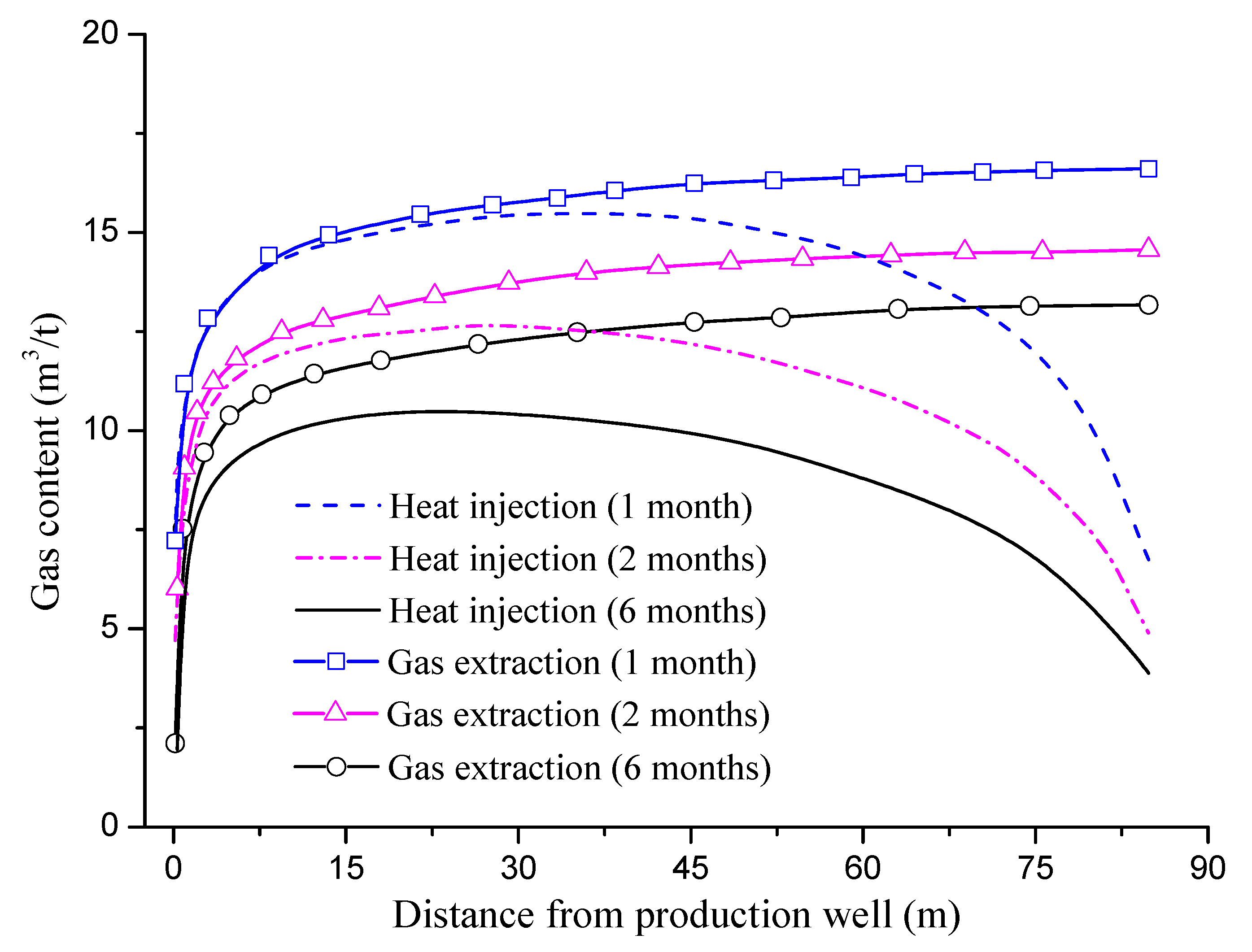
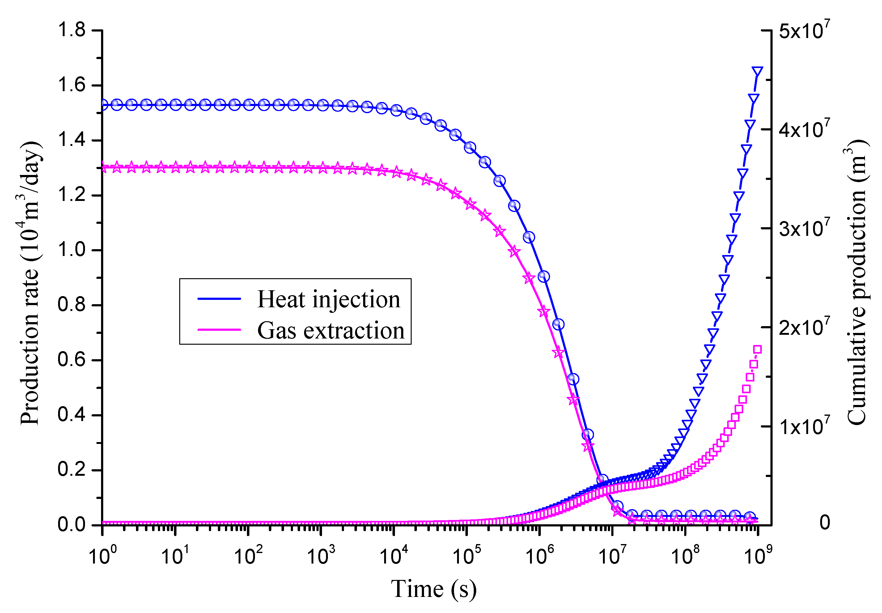
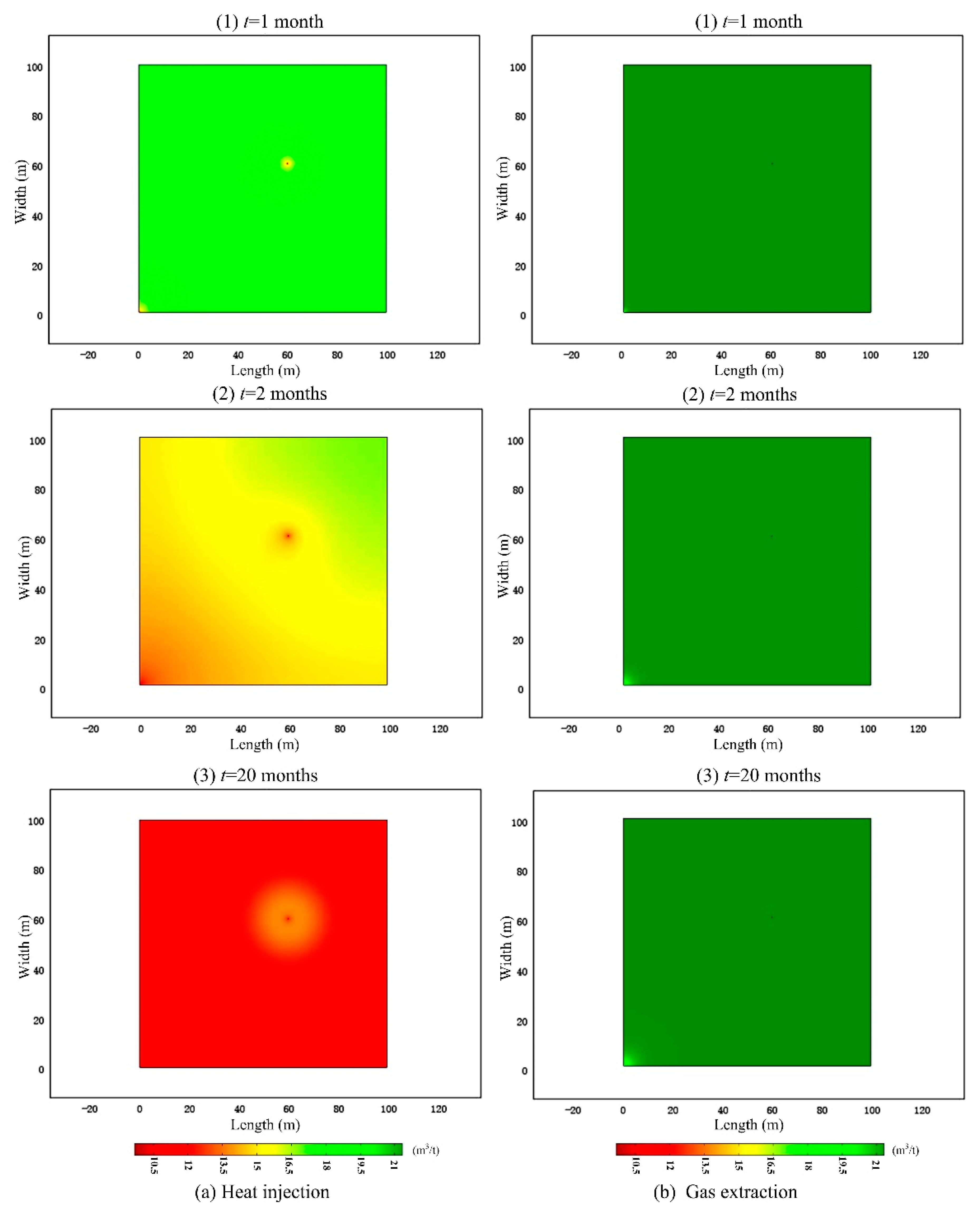
4.3. Gas Content and Gas Production during Heat Injection

The evolution law of the gas content in coal seam is analyzed in this section. The gas content of coal seam can be obtained from Equation (4). Figure 10a displays a method to increase the CBM recovery by heat injection, whereas Figure 10b exhibits a traditional CBM recovery method. The gas content in coal changes more rapidly in the case of heat injection. In the absence of a heat source, the gas content in the coal seam changes very slowly. After heat injection, the gas content varies not only in the vicinity of the drainage borehole but also in the thermally affected zone. For example, the gas content of point C is 18.51 m3/t for 1 month. However, the gas content is 15.59 m3/t for 2 months, while the gas content is 21.14 m3/t without heat injection for 2 months. Overall, the gas content is consistent of with the absorbed gas and free gas. Temperature usually has an obvious influence on the absorbed gas owing to the thermal desorption effect.
The evolution of the absorbed gas content in the coal seam is shown in Figure 11. The absorbed gas content is related to the air pressure and reservoir temperature and can be obtained from Langmuir adsorption (Equation (5)). The initial coal seam absorbed gas content is 16.6 m3/t. The change in the absorbed gas content caused by the gas drainage is very slow. Even after the gas is drained for six months, the absorbed gas content far from the borehole is high. For example, for the drainage time 1 month, 2 months and 6 months, the absorbed gas content of point B are 11.05 m3/t, 8.08 m3/t and 6.11 m3/t, respectively, under the heat injection condition. However, without heat injection, the absorbed gas content of point B are 16.57 m3/t, 14.51 m3/t and 13.14 m3/t, respectively. The gas drainage in low-permeability coal seam is restrained. After heat injection, the absorbed gas content is reduced not only near the borehole but also in the heat affected zone, owing to the heat-promoted gas desorption. A high temperature implies a decrease in the absorbed gas content. After gas drainage for six months, the absorbed gas content decreases to 3.8 m3/t, which is much lower than that without heat injection (13.1 m3/t).
The gas production rates of different extraction methods can be seen from Figure 12. An obvious difference can be seen from the figure. The gas injection rate of the gas production is relatively high with the increase in time. Simultaneously, the gas production rate continues to decline, and finally reaches a stable state. In the last stationary stage, the gas production rate of injection heating fluctuates, whereas ordinary extraction maintains a steady rate. The gas production rate of the injection heat is 1.52 × 10⁴ m3/d and 0.94 × 10⁴ m3/d at 102 s and 106 s, respectively, and the gas production rate of common extraction is 1.31 × 10⁴ m3/d and 0.81 × 10⁴ m3/d, which is 85.0% and 86.9% of that in case of the injection heat. Figure 12 shows the cumulative gas productions obtained by different extraction methods. With the two types of gas drainage methods, in the initial stage, the two types of drainage quantities are relatively low before 105 s, whereas the cumulative gas production of the two drainage methods continues to increase. With the increase in time, the cumulative gas production exhibits a significant difference. The heat injection drainage quantity is 4.61 × 10⁷ m3, whereas the ordinary drainage accumulated gas production is 1.78 × 10⁷ m3 at 109 s.

5. Conclusions

In this work, to analyze the evolution of porosity during heat injection, a fully coupled thermo-hydro-mechanical model was proposed. This model is suitable for coal compaction, thermal expansion, heat-induced gas desorption, and adsorption of coal deformation. The coal deformation caused by thermal-induced gas desorption has a more prominent effect on the porosity than other factors.
The increase in the temperature also accelerates the flow of the gas, which is beneficial for gas extraction. The permeability of the boreholes above 20 m is increased by approximately 30% in two months, compared with the initial condition of gas production. As the injection heat continues, the average temperature of the entire coal seam increases. At high temperatures, owing to the gas desorption, the permeability of the heat affected zone can be significantly improved by heat injection. The maximum of permeability ratio increases to 3.34 at 20 months.
The gas content in coal changes more rapidly with heat injection. After gas drainage for six months, the absorbed gas content decreases to 3.8 m3/t, which is much lower than that without heat injection (13.1 m3/t). In the absence of a heat source, the gas content in the coal seam changes very slowly while the gas content changes significantly in the thermally affected zone after heat injection. The gas content of point C is 15.59 m3/t for 2 months, while the gas content is 21.14 m3/t without heat injection.
Heat injection can significantly increase the gas production rate and cumulative gas production. After heat injection, the gas composition varies not only in the vicinity of the production well but also in the thermally affected zone. The gas production rate of common extraction is 1.31 × 10⁴ m3/d and 0.81 × 10⁴ m3/d, which is only 85.0% and 86.9% of that in case of the injection heat.
In this paper, the heat and gas transfer characteristics during heat injection process is analyzed through numerical simulation. The next step is to conduct laboratory tests and field tests to further enhance the practicability of the model.

Author Contributions

Y.X. and F.D. conceived the model; Y.X., Z.C. and F.L. performed the numerical simulation; Y.X. and F.G. wrote the paper; Y.X., F.D. and J.R. revised the paper.

Funding

This study is sponsored by the National Natural Science Foundation of China (no. 51679199), the China Postdoctoral Science Foundation (no. 2018M633549), the Special Funds for Public Industry Research Projects of the Ministry of Water Resources (nos. 201501034-04 and 201201053-03), the Initiation Fund of Doctor’s Research (no. 107-451117008) and the Key Laboratory for Science and Technology Coordination & Innovation Projects of Shaanxi Province (no. 2014SZS15-Z01).

Conflicts of Interest

The authors declare no conflict of interest.

Appendix A

Table A1. Parameters used for historic production simulation (Reservoir investigation from Mora et al. [50]).
VariableDescriptionUnitValue
p0Initial average pressureMPa4.82
ϕ0Fracture porosity0.015
k0Initial permeability of coalmD5
ρcDensity of coalkg/m31.52 × 103
VLLangmuir volume constantMPa1.93
PLLangmuir pressure constantm3/kg0.048
T0Initial temperature of coal seam°C21.1
EYoung’s modulus of coalMPa1119
ν Poisson’s ratio of coal0.5
υ Dynamic viscosity coefficient of gasPa·s1.1 × 106

References

  1. Xue, Y.; Ranjith, P.G.; Gao, F.; Zhang, D.; Cheng, H.; Chong, Z. Mechanical behaviour and permeability evolution of gas-containing coal from unloading confining pressure tests. J. Nat. Gas Sci. Eng. 2017, 40, 336–346. [Google Scholar] [CrossRef]
  2. Yang, S.Q.; Chen, M.; Jing, H.W.; Chen, K.F.; Meng, B. A case study on large deformation failure mechanism of deep soft rock roadway in Xin’an coal mine, China. Eng. Geol. 2017, 217, 89–101. [Google Scholar] [CrossRef]
  3. Xie, H.; Ju, Y.; Gao, F.; Gao, M.; Zhang, R. Groundbreaking theoretical and technical conceptualization of fluidized mining of deep underground solid mineral resources. Tunn. Undergr. Space Technol. 2017, 67, 68–70. [Google Scholar] [CrossRef]
  4. Wanniarachchi, W.A.M.; Ranjith, P.G.; Perera, M.S.A.; Rathnaweera, T.D.; Zhang, C.; Zhang, D.C. An integrated approach to simulate fracture permeability and flow characteristics using regenerated rock fracture from 3-d scanning: A numerical study. J. Nat. Gas Sci. Eng. 2018, 53, 249–262. [Google Scholar] [CrossRef]
  5. Kanduč, T.; Zavšek, S.; Jamnikar, S.; Verbovšek, T. Spatial distribution and origin of coalbed gases at the working faces of the Velenje Coal Basin, Slovenia, since the year 2000. Mater. Geoenviron. 2016, 63. [Google Scholar] [CrossRef]
  6. Zhang, D.; Ranjith, P.G.; Perera, M.S.A. The brittleness indices used in rock mechanics and their application in shale hydraulic fracturing: A review. J. Nat. Gas Sci. Eng. 2016, 143, 158–170. [Google Scholar] [CrossRef]
  7. Zhang, J.Q.; Ren, S.M. Investigation Project of Coal Bed Gas and Other Unconventional Energy Mineral Resources; Oil and Gas Resources Survey of China Geological Survey: Beijing, China, 2014. [Google Scholar]
  8. Zheng, C.; Lin, B.; Kizil, M.; Aminossadati, S.; Li, H.; Chen, Z. Analysis on the multi-phase flow characterization in cross-measure borehole during coal hydraulic slotting. Int. J. Min. Sci. Technol. 2018. [Google Scholar] [CrossRef]
  9. Noack, K. Control of gas emissions in underground coal mines. Int. J. Coal Geol. 1998, 35, 57–82. [Google Scholar] [CrossRef]
  10. Vizintin, G.; Mayer, J.; Lajlar, B.; Vukelic, Z. Rock burst dependency on the type of steel arch support in the velenje mine. Mater. Technol. 2017, 51. [Google Scholar] [CrossRef]
  11. Zhang, S.; Liu, J.; Wei, M.; Elsworth, D. Coal permeability maps under the influence of multiple coupled processes. Int. J. Coal Geol. 2018, 187, 71–82. [Google Scholar] [CrossRef]
  12. Pan, Z.; Connell, L.D. Modelling permeability for coal reservoirs: A review of analytical models and testing data. Int. J. Coal Geol. 2012, 92, 1–44. [Google Scholar] [CrossRef]
  13. Kanduc, T.; Grassa, F.; Lazar, J.; Zavšek, S. Geochemical and isotopic characterization of coalbed gases in active excavation fields at Preloge and Pesje (Velenje Basin) mining areas. RMZ M&G 2015, 62, 21–36. [Google Scholar]
  14. Warren, J.E.; Root, P.J. The behavior of naturally fractured reservoirs. Soc. Pet. Eng. J. 1963, 3, 245–255. [Google Scholar] [CrossRef]
  15. Robertson, E.P.; Christiansen, R.L. Modeling laboratory permeability in coal using sorption-induced strain data. SPE Reserv. Eval. Eng. 2007, 10, 260–269. [Google Scholar] [CrossRef]
  16. Cui, X.; Bustin, A.M.M.; Bustin, R.M. Measurements of gas permeability and diffusivity of tight reservoir rocks: Different approaches and their applications. Geofluids 2009, 9, 208–223. [Google Scholar] [CrossRef]
  17. Shi, J.Q.; Durucan, S.; Shimada, S. How gas adsorption and swelling affects permeability of coal: A new modelling approach for analysing laboratory test data. Int. J. Coal Geol. 2014, 128, 134–142. [Google Scholar] [CrossRef] [Green Version]
  18. Liu, J.; Chen, Z.; Elsworth, D.; Miao, X.; Mao, X. Linking gas-sorption induced changes in coal permeability to directional strains through a modulus reduction ratio. Int. J. Coal Geol. 2010, 83, 21–30. [Google Scholar] [CrossRef]
  19. Salmachi, A.; Haghighi, M. Feasibility study of thermally enhanced gas recovery of coal seam gas reservoirs using geothermal resources. Energy Fuels 2012, 26. [Google Scholar] [CrossRef]
  20. Tong, F.; Jing, L.; Zimmerman, R.W. A fully coupled thermo-hydro-mechanical model for simulating multiphase flow, deformation and heat transfer in buffer material and rock masses. Int. J. Rock Mech. Min. 2010, 47, 205–217. [Google Scholar] [CrossRef]
  21. Xia, T.; Zhou, F.; Liu, J.; Kang, J.; Gao, F. A fully coupled hydro-thermo-mechanical model for the spontaneous combustion of underground coal seams. Fuel 2014, 125, 106–115. [Google Scholar] [CrossRef]
  22. Yao, B.; Wu, Y.; Liu, J. The effect of the fracture distribution on co2 injection into a coal seam. Int. J. Min. Sci. Technol. 2012, 22, 115–120. [Google Scholar] [CrossRef]
  23. Zhang, H.; Liu, J.; Elsworth, D. How sorption-induced matrix deformation affects gas flow in coal seams: A new fe model. Int. J. Rock Mech. Min. 2008, 45, 1226–1236. [Google Scholar] [CrossRef]
  24. Zhang, L.; Zhang, H.; Guo, H. A case study of gas drainage to low permeability coal seam. Int. J. Min. Sci. Technol. 2017, 27, 687–692. [Google Scholar] [CrossRef]
  25. Xue, D.J.; Zhou, H.W.; Chen, C.F.; Jiang, D.Y. A combined method for evaluation and prediction on permeability in coal seams during enhanced methane recovery by pressure-relieved method. Environ. Earth Sci. 2015, 73, 5963–5974. [Google Scholar] [CrossRef]
  26. Li, C.W.; Fu, S.; Cui, Y.G.; Sun, X.Y.; Xie, B.J.; Yang, W. Study of the migration rule of high-concentration gas and spatial-temporal feature of gas hazard in the tunnel. J. China Univ. Min. Technol. 2017, 46, 27–32. [Google Scholar]
  27. Cao, Z.Z.; Du, F.; Xu, P.; Lin, H.X.; Xue, Y.; Zhou, Y.J. Control Mechanism of Surface Subsidence and Overburden Movement in Backfilling Mining based on Laminated Plate Theory. CMC 2017, 53, 187–202. [Google Scholar] [CrossRef]
  28. Wang, S.; Zhou, F.; Kang, J.; Wang, X.; Li, H.; Wang, J. A heat transfer model of high-temperature nitrogen injection into amethane drainage borehole. J. Nat. Gas Sci. Eng. 2015, 24, 449–456. [Google Scholar] [CrossRef]
  29. Xue, Y. Numerical simulation of coal deformation and gas flow properties around borehole. CMES 2017, 113, 429–441. [Google Scholar] [CrossRef]
  30. Yang, S.Q.; Ranjith, P.G.; Jing, H.W.; Tian, W.L.; Ju, Y. An experimental investigation on thermal damage and failure mechanical behavior of granite after exposure to different high temperature treatments. Geothermics 2017, 65, 180–197. [Google Scholar] [CrossRef]
  31. Vižintin, G.; Kocjančič, M.; Vulić, M. Study of coal burst source locations in the velenje colliery. Energies 2016, 9. [Google Scholar] [CrossRef]
  32. Chu, T.; Jiang, D.; Yu, M. Experimental study of the seepage properties of the compacted particle coal under gradual loading. J. China Univ. Min. Technol. 2017, 46, 1058–1065. [Google Scholar]
  33. Yang, S.Q.; Hu, B.; Ranjith, P.; Xu, P. Multi-step loading creep behavior of red sandstone after thermal treatments and a creep damage model. Energies 2018, 11. [Google Scholar] [CrossRef]
  34. Shahtalebi, A.; Khan, C.; Dmyterko, A.; Shukla, P.; Rudolph, V. Investigation of thermal stimulation of coal seam gas fields for accelerated gas recovery. Fuel 2016, 180, 301–313. [Google Scholar] [CrossRef]
  35. Yhya, N.; Kashif, M.; Nasir, N.; Niaz Akhtar, M.; Yusof, N.M. Cobalt ferrite nanoparticles: An innovative approach for enhanced oil recovery application. J. Nano Res. 2012, 17, 115–126. [Google Scholar] [CrossRef]
  36. Elahi, S.M.; Nassir, M.; Chen, Z. Effect of various coal constitutive models on coupled thermo-mechanical modeling of underground coal gasification. J. Pet. Sci. Eng. 2017, 154, 469–478. [Google Scholar] [CrossRef]
  37. Zhou, F.; Hussain, F.; Cinar, Y. Injecting pure N2, and CO2, to coal for enhanced coalbed methane: Experimental observations and numerical simulation. Int. J. Coal Geol. 2013, 116, 53–62. [Google Scholar] [CrossRef]
  38. Qu, H.; Liu, J.; Chen, Z.; Wang, J.; Pan, Z.; Connell, L.; Elsworth, D. Complex evolution of coal permeability during CO2, injection under variable temperatures. Int. J. Greenh. Gas Control 2012, 9, 281–293. [Google Scholar] [CrossRef]
  39. Mutyala, S.; Fairbridge, C.; Paré, J.R.J.; Bélanger, J.M.R.; Ng, S.; Hawkins, R. Microwave applications to oil sands and petroleum: A review. Fuel Process. Technol. 2010, 91. [Google Scholar] [CrossRef]
  40. Li, H.; Lin, B.; Yang, W.; Hong, Y.; Wang, Z. A fully coupled electromagnetic-thermal-mechanical model for coalbed methane extraction with microwave heating. J. Nat. Gas Sci. Eng. 2017, 46, 830–844. [Google Scholar] [CrossRef]
  41. Yin, G.; Jiang, C.; Wang, J.G.; Xu, J. Combined effect of stress, pore pressure and temperature on methane permeability in anthracite coal: An experimental study. Transp. Porous Media 2016, 100, 1–16. [Google Scholar] [CrossRef]
  42. Pan, J.; Hou, Q.; Ju, Y.; Bai, H.; Zhao, Y. Coalbed methane sorption related to coal deformation structures at different temperatures and pressures. Fuel 2012, 102, 760–765. [Google Scholar] [CrossRef]
  43. Zhang, Z.; Zhang, R.; Xie, H.; Gao, M.; Zha, E.; Jia, Z. An anisotropic coal permeability model that considers mining-induced stress evolution, microfracture propagation and gas sorption-desorption effects. J. Nat. Gas Sci. Eng. 2017, 46, 664–679. [Google Scholar] [CrossRef]
  44. Chen, D.; Pan, Z.; Shi, J.Q.; Si, G.; Ye, Z.; Zhang, J. A novel approach for modelling coal permeability during transition from elastic to post-failure state using a modified logistic growth function. Int. J. Coal Geol. 2016, 163, 132–139. [Google Scholar] [CrossRef]
  45. Liu, J.; Chen, Z.; Elsworth, D.; Qu, H.; Chen, D. Interactions of multiple processes during CBM extraction: A critical review. Int. J. Coal Geol. 2011, 87, 175–189. [Google Scholar] [CrossRef]
  46. Xue, Y.; Dang, F.; Li, R.; Fan, L.; Hao, Q.; Mu, L.; Xia, Y. Seepage-stress-damage coupled model of coal under geo-stress influence. CMC 2018, 54, 43–59. [Google Scholar] [CrossRef]
  47. Klinkenberg, L.J. Analogy between diffusion and electrical conductivity in porous rocks. Geol. Soc. Am. Bull. 1951, 62. [Google Scholar] [CrossRef]
  48. Wu, Y.S.; Pruess, K.; Persoff, P. Gas flow in porous media with Klinkenberg effects. Transp. Porous Media 1998, 32, 117–137. [Google Scholar] [CrossRef]
  49. Zhu, W.C.; Wei, C.H.; Liu, J.; Qu, H.Y.; Elsworth, D. A model of coal–gas interaction under variable temperatures. Int. J. Coal Geol. 2011, 86, 213–221. [Google Scholar] [CrossRef]
  50. Mora, C.A.; Wattenbarger, R.A. Comparison of computation methods for CBM performance. J. Can. Pet. Technol. 2009, 48, 42–48. [Google Scholar] [CrossRef]
Figure 1. Thermo-hydro-mechanical model for coalbed methane extraction.
Energies 11 01722 g001
Figure 2. Model validation through comparisons with previous models. (a) Distribution of gas pressure calculated by two models; (b) Evolutions of the coal permeability and gas pressure calculated by two models.
Energies 11 01722 g002
Figure 3. Comparison of the gas production rate between the modeling result and historic data.
Energies 11 01722 g003
Figure 4. Computational model and schematic of the heat injection well.
Energies 11 01722 g004
Figure 5. Temperature evolution characteristics at different times. (a) 3 days; (b) 1 month; (c) 2 months; (d) 10 months; (e) 20 months; (f) 30 months.
Energies 11 01722 g005
Figure 6. Temperature evolution at three specific points.
Energies 11 01722 g006
Figure 7. Evolution of gas pressure along the link-line of two wells at different times.
Energies 11 01722 g007
Figure 8. Permeability ratio evolution of coal seam after different production time (k/k0). (a) 1 month; (b) 2 months; (c) 10 months; (d) 20 months.
Energies 11 01722 g008
Figure 9. Contributions of different coal–gas interactions to coal porosity at point A.
Energies 11 01722 g009
Figure 10. Distribution of the gas content in the coal seam by two extraction methods. (a) heat injection; (b) gas extraction.
Energies 11 01722 g010
Figure 11. Evolution of the absorbed gas content in the coal matrix after different production times.
Energies 11 01722 g011
Figure 12. Gas production rate and cumulative production with two extraction methods.
Energies 11 01722 g012
Table 1. Parameters used for one-dimensional linear steady gas flow.
ParameterValue
Young’s modulus of coal (E, MPa)2700
Young’s modulus of the coal grains (Es, MPa)7100
Density of coal ( ρ c , kg/m3)1380
Poisson’s ratio of coal ( ν , -)0.38
Initial gas permeability ( k 0 , m2)5.0 × 10⁻¹⁹
Compressibility factor, (Mc/RT, kg/(Pa·m−3))1.18 × 10−5
Gas dynamic viscosity ( υ , N·s/m2)1.84 × 10−5
Length of the rock column (L, m)20
Table 2. Property parameters used in the simulation model.
ParameterValue
Young’s modulus of coal (E, MPa)2700
Young’s modulus of the coal grains (Es, MPa)7100
Initial porosity (φ0, -)0.01
Density of coal (ρc, kg/m3)1380
Poisson’s ratio of coal (ν, -)0.38
Initial gas permeability (k0, m2)1.09 × 10⁻¹⁸
Density of CH4 at standard condition (ρg, kg/m3)0.717
Gas dynamic viscosity (υ, N·s/m2)1.84 × 10−5
CH4 Langmuir pressure constant (PL, MPa)1.57
CH4 Langmuir volume constant (VL, m3/kg)0.043
Specific heat capacity of gas (Cg, J/kg·K)1.005 × 103
Specific heat capacity of coal (Cs, J/kg·K)1.25 × 103
Pressure coefficient (c1, MPa−1)0.07
Coefficient for sorption-induced volumetric strain (αsg, kg/m3)0.06
Volumetric thermal expansion of the solid matrix coefficient (αT, K−1)2.4 × 10⁻⁵
Klinkenberg effect (b, Pa)1.44 × 10⁵
Temperature coefficient (c2, MPa−1)0.02
Thermal conductivity of coal (λs, J/m·s·K)0.2
Table 3. Initial and boundary conditions in the reservoir simulation.
FieldCoal DeformationGas FlowHeat Flow
Initial valueSame as following3.0 MPa293 K
Boundary valueOPNormal displacement constraintNo flowThermal insulation
PQNormal displacement constraintNo flowThermal insulation
QRNormal displacement constraintNo flowThermal insulation
RONormal displacement constraintNo flowThermal insulation
Heat injection well362.4 K
Gas production wellFree0.1 MPaThermal insulation

