Grid Integration and Power Smoothing of an Oscillating Water Column Wave Energy Converter


1
Australian Maritime College, University of Tasmania, Launceston, Tasmania 7250, Australia
2
Centre for Renewable Energy and Power Systems, University of Tasmania, Hobart, Tasmania 7001, Australia
*
Author to whom correspondence should be addressed.
Energies 2018, 11(7), 1871; https://doi.org/10.3390/en11071871
Submission received: 7 June 2018
/
Revised: 26 June 2018
/
Accepted: 13 July 2018
/
Published: 18 July 2018
(This article belongs to the Special Issue Wave and Tidal Energy)
Abstract
:This paper applies model predictive control (MPC) for the power processing of an oscillating water column (OWC) wave energy conversion (WEC) system to achieve smooth power delivery to the grid. The particular air turbine design adopted in this study produces large power pulses ranging from 0 to 1 MW in magnitude, and thus, direct connection to the grid is practically impossible, especially in weak grid conditions. Therefore, energy storage is an essential element that should be integrated into this particular WEC system in order to absorb power pulses and thereby ensure smooth delivery of power to the grid. Taking into account the repetitive nature, duration, and magnitude of the power pulses, this study has chosen “supercapacitor” as the suitable energy storage technology. The supercapacitor energy storage (SCES) is integrated into the dc-link of the back-to-back power converter of the WEC system through a bidirectional dc-dc converter. In order to achieve the desired operation of this complex power converter arrangement, a finite control set MPC strategy is proposed in this paper. Performance of the proposed energy storage system (ESS) and control strategy are evaluated through computer simulations. Simulation results show that the proposed SCES system and the control strategy are able to achieve smooth power delivery to the grid amidst power pulses coming from the generator.
1. Introduction
Oceans, which cover 70% of the Earth, offer a vast amount of renewable energy. Out of many forms, wave energy is an accessible and widely available type of ocean energy. Recent studies have shown that wave energy has the potential to make significant contributions to renewable energy targets worldwide [1,2,3]. Australia has been identified as a wave-energy-rich country, having the potential to extract more energy from waves than its total annual electricity demand [2]. Recognizing this potential, many companies have invested in wave energy projects in Australia [3,4,5]. Out of the many technologies used to harness energy from waves, oscillating water column (OWC) based wave energy conversion (WEC) technology has the advantage of having all of its moving parts above the water level, allowing relatively straightforward installation and easy access for maintenance [2,6]. These are key factors for cost reduction in any renewable energy technology and thus, with the improved performance, OWC wave energy converters will be able to compete with other renewable and fossil-fuel energies in the energy market.
The OWC concept utilizes a water column inside a partially submerged hollow concrete structure. With the incident wave, the OWC inside the chamber oscillates the air column above it and results in exhale and inhale air streams through the open end of the chamber. Energy of the air stream is then converted into electricity with the aid of a turbine coupled generator. The commonly used turbines are bidirectional which extract energy from both the inhale and exhale streams.
The Australian maritime college, in collaboration with the Wave Swell Energy Ltd., has developed a new OWC air turbine technology, which has been recognized as an efficient and simple design compared with many other OWC technologies [6,7]. This particular configuration has passive, non-return air flow valves built into its chamber, which activate during the exhale stage and equalize the pressure inside the chamber to the atmosphere, which allows the rising water column to reach its maximum height. This creates a higher differential pressure during the inhale stage resulting in high velocity air stream through the turbine. Since this particular air turbine extracts energy only during the inhale stage, the output power inherently becomes discrete pulses. These large and discrete power pulses create major operational issues, such as frequency deviations, voltage sags/swells, and instabilities if delivered to the grid without smoothing. Therefore, energy storage is an essential feature that should be incorporated into the power converter of the WEC system. Nevertheless, in contrast to wind energy or tidal energy turbines, where the rotational speed should be changed according to the wind speed or tidal flow speed, the unidirectional air-turbine used in this study does not necessarily require variable speed operation. Therefore, according to [8], the turbine speed can be regulated to remain within the optimum speed range irrespective of the air flow. This eliminates the need for complex maximum power point tracking strategies, and thus, the machine side converter controller becomes relatively less complex. However, the abovementioned large and discrete power pulses are unique to this WEC system compared to other types of OWC WEC systems, and thus, special attention has to be paid when developing associated control strategies.
As mentioned above, the promising approach to overcome the issues related to power pulses is the use of an energy storage system (ESS). The ESS absorbs power pulses to provide smooth power delivery to the grid. A comprehensive review of ESSs in renewable energy electric power systems is presented in [9]. Hamidi et al. [9] have discussed different types of batteries, supercapacitors, and hybrid energy storage system (HESS) along with their modeling techniques. They have also highlighted different utility-level power converter topologies and given six examples of ESSs in field installations. Some of the desirable qualities of ESSs are emphasized in [10], as high charge-discharge efficiency, high energy density, volume power density, high specific energy, high specific power with continuous power supply, long life, relatively cheaper value per usable kWh per cycle, and so forth. The evidence confirms that supercapacitors lead the energy storage market with high-power density, whereas the Li-ion batteries lead the industry with high energy density. Generally, one or both of these ESSs are used in renewable energy applications depending on the requirements [11,12]. This study applies a commercially available supercapacitor to smoothen the output power of the unidirectional air turbine OWC system. The supercapacitor energy storage (SCES) has high energy storage efficiency and very high cycling stability with insignificant loss of energy storage capacity [13]. A full-scale offshore OWC WEC system has been investigated in [14], in which it was confirmed that supercapacitors are capable of power smoothing satisfactorily over desirable long periods. Figure 1, illustrates a grid-connected OWC WEC system with SCES.
In [15], the authors have proposed to use a Li-ion battery energy storage (BES) system, which is directly connected to the dc-link to absorb power pulses. It has used the finite control set-model predictive control (FCS-MPC) strategy for the rectifier and inverter of the back-to-back power converter. Due to the fact that the two controllers indirectly control the battery current and the dc-link voltage is governed by the battery, direct connection is possible for batteries. If supercapacitors are used as the energy storage element, direct connection to the dc-link is not effective, as the voltage should be allowed to vary in a wide range to store more energy in the supercapacitors. Therefore, an interfacing dc-dc converter is essential for integrating supercapacitors into the power converter system. While the rectifier and inverter controllers proposed in [15] can still be used, the dc-dc converter requires an additional converter.
The use of dc-dc bidirectional converters with energy storage, such as a battery and/or supercapacitor are common in utility-level renewable energy systems, which act fast to reduce the mismatch between the supply and demand power [9]. Several types of such converters have been presented in [9], which can be used as energy storage interface systems. The half bridge (HB)-type converters are more effective than many other types as they use a lower number of passive electronics, smaller inductors, and experience lower current stresses. In [11,16,17], an ESS with a HB dc-dc bidirectional converter for a grid-connected renewable energy systems was proposed and explained converter control algorithms using proportional integral (PI) control strategy. Also, Maercos et al. [11] have provided a battery supercapacitor HESS and a literature review of 18 similar approaches with respect to their application, system, topology, rated power, comparison, sizing, control, and goals related to applications such as energy harvesting, microgrids, remote area power supply, load supply, and so forth.
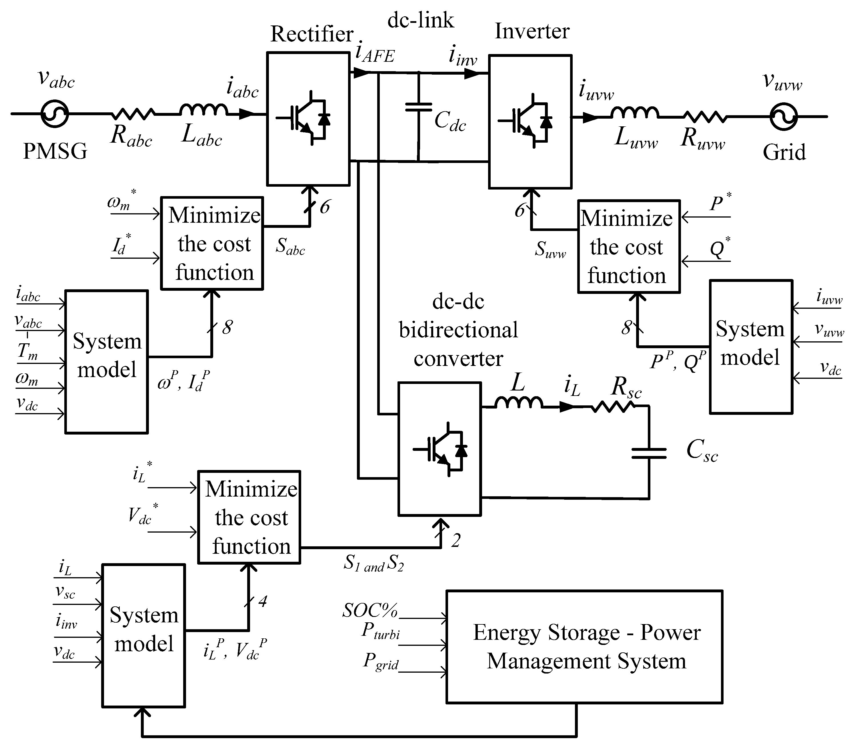
To gain the desirable results from any ESS, which is connected to the dc-link through an interfacing converter, one needs an effective control system. In this research, applying FCS-MPC strategy for the dc-dc bidirectional converter controller has been achieved. Figure 2 depicts the schematic diagram of the controllers that are used for the electrical power converters.
The model predictive control (MPC) approach is chosen to control the converters due to its simple, fast, accurate, and reliable nature [15,18,19]. In [20], the same control strategy has been applied to a dc-dc bidirectional converter with mode activation approach, where charge, discharge, and idle modes were designed to operate independently. In [21], a SCES coupled to the dc-link with a dc-dc bidirectional converter was proposed for the wells turbine OWC system using field-oriented control (FOC) strategy. Also, a performance comparison was done between SCES and fixed and variable speed flywheel ESSs referring to [17,22,23]. In [24], a HESS has been used for oscillating wave power generator, applying sliding mode control strategy for the whole system. Nevertheless, the feasibility of using supercapacitors for the particular WEC system considered in this study, from the control perspective, is not reported so far. Therefore, the contributions of this paper are to propose SCES for this particular WEC system, develop a FCS-MPC strategy for the entire power converter system, and verify its performance through computer simulations.
The paper is organized as follows: Section 2 presents the modeling of SCES; Section 3 presents the MPC for the electrical power converter, followed by the power management system presented in Section 4; Section 5 presents the simulation results and discusses the implications of the results; and the conclusions derived from the discussion are presented in Section 6.
2. Supercapacitor Energy Storage
This study uses a supercapacitor bank as the energy storage element, which is connected to the dc-link through a bidirectional dc-dc converter. Supercapacitors have the advantage of long life, high-power density, attractive temperature range, and high charge-discharge efficiency [10]. The SCES is integrated into the OWC electrical power converter system to achieve smooth power delivery to the grid despite varying sea conditions. With the recent advancements of energy storage technologies, supercapacitors have become popular and commercially available for large power applications, such as WEC systems. The supercapacitor specification sheet in [25], confirms that the industrial 83 F or 165 F supercapacitor single modules with 48 Vdc can be connected in series and/or parallel configurations to gain the required voltage and capacity. Moreover, these modules provide up to 1,000,000 charge/discharge cycles. In this particular system, to attain the required voltage of the SCES (1000 V), a minimum 21 of 48 V modules are needed to connect in series, which results in the decrease of the total capacitance and increase of the internal resistance () in each pole. Then, these high voltage modules can be connected in parallel to obtain the required total capacitance to gain the energy storage capacity that decreases . Considering , which represents only static losses, the stored energy and instantaneous voltage of the supercapacitor are given by the following [26]:
where is the supercapacitor energy, is the capacitance of the supercapacitor, is the voltage across the supercapacitor, and are the initial voltage and charge of the supercapacitor, respectively.
The state of charge (SOC) of the supercapacitor can be estimated using Equation (3):
where and are the supercapacitor current at time t and total charge, respectively. It should be noted that the method shown in Equation (3) is one of the conventional methods of estimation of SOC, and the nominal capacity decreases gradually over time due to variations in load and the internal chemical reactions. More advanced SOC estimation methods are discussed in [27,28].
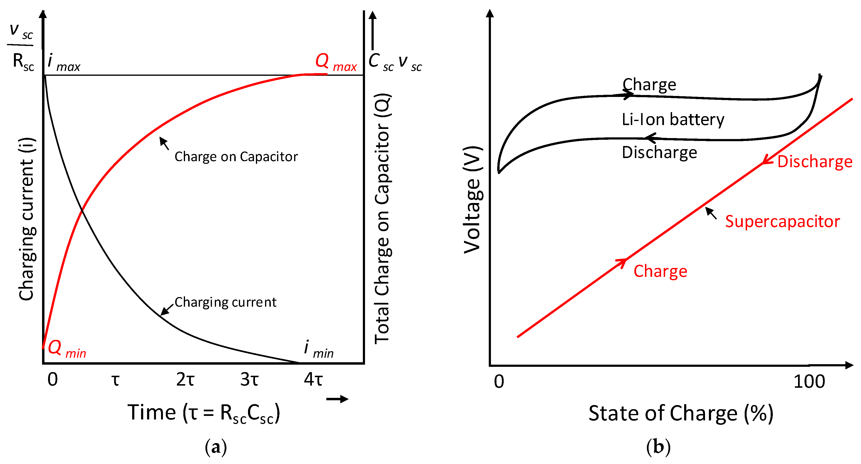
The supercapacitor charge () is equal to the product of its capacitance and voltage . Therefore, changes with respect to and vice versa. Figure 3a shows a typical supercapacitor charge/current behavior with respect to the time, and Figure 3b, shows the charge/discharge curves of a supercapacitor and Li-ion battery.
3. Model Predictive Control-Based Converter Control Strategies
3.1. Rectifier Controller
As in [15], the input current dynamics of the rectifier were found using Kirchhoff’s voltage law, and the resultant equation for the predicted current in the next sampling interval was written in the discrete time domain as follows:
where is the rectifier input current vector, is the combination of source and line filter resistance, is the combination of source and line filter inductance, is the sampling instant, is the sampling time, is the generator voltage vector, and is the rectifier voltage vector. The generator current in the next sampling interval, , was predicted for each of the eight switching states using Equation (4). The current value was then converted into the dq frame currents, , , and used to predict the future angular speed of the generator, as in [15]:
where is the mechanical torque applied on the motor, is the number of pole pairs, and is the permanent magnet synchronous generator (PMSG) flux. Then, the values and were used in the cost function, , given in Equation (6) to select the switching state that gives the minimum value for the cost function [15].
where is the reference speed and is the reference for the d-axis current component of the generator, which was set to zero. The arbitrary constant, K, has been used in the equation to reduce the d axis current of the generator aiming to prevent flux weakening and overheating effects on the PMSG [15].
3.2. Inverter Controller
As in [15], in the inverter controller, three-phase grid current, and grid voltage, were converted into the αβ stationary reference frame using the Clark’s transformation, as in [32]:
where f represents current or voltage. Then, the input current dynamics of the inverter were found using Kirchhoff’s voltage law. The resultant equation for the predicted current in the next sampling interval was written in the discrete time domain as follows [15]:
where is the inverter voltage vector, is the combination of grid and line filter resistance, and is the combination of grid and line filter inductance. The grid current in the next sampling interval, , was predicted for each of the eight switching states using Equation (8). Then, each of the current values were converted into the dq frame currents and used to predict the power values, and considering the as follows [15]:
where , , , and are grid currents and grid voltages in a dq rotating reference frame. The values and were used in the cost function, , given in Equation (11) to select the switching state that gives the minimum value for the cost function [15].
where is the active power reference, which was set to 265kW, and is the reactive power reference for the grid, which was set to zero.
3.3. DC-DC Converter Controller
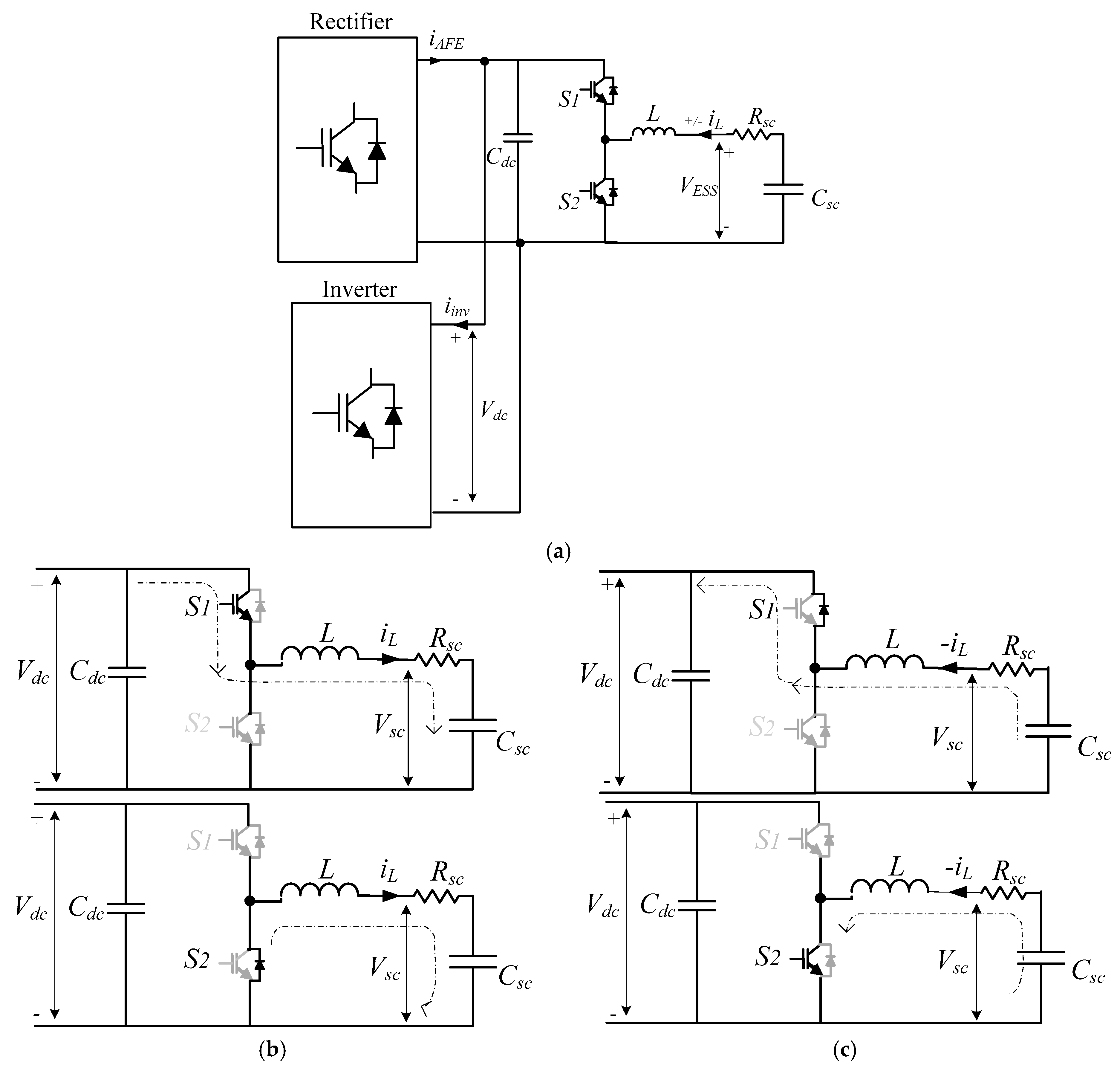
Generally, the voltage of the ESS (battery and/or supercapacitor) is lower than the dc-link voltage and the polarity of the energy storage, and its output is set to the same with respect to the common ground. The dc-dc bidirectional converter is suited well for this type of application, because proper control of the switches regulate the dc-link power fluctuations by directing them to the energy storage [33,34,35]. This is a simple converter, which can be used in high-power applications where the switch rating of the converter becomes the key concern [23,36]. This converter consists of two insulated gate bipolar transistor (IGBT) switches, two anti-parallel diodes, and an inductor connected as shown in Figure 4a. This dc-dc bidirectional converter is a combination of buck and boost topologies, as shown in Figure 4b,c, respectively.
In this type of converter, the inductor is the main energy transfer element, which is also responsible for the output current ripple. The ESS can be either a battery or supercapacitor and is connected to the low-voltage side. The high-voltage side of the converter is connected to the dc-link. The converter is designed to operate in both buck and boost modes. This two-quadrant dc-dc converter allows inductor current flow in either direction while keeping the polarity of the dc voltage fixed during the boost and buck modes. The mode it should operate at any given time is decided by the dc-link voltage and the voltage of the energy storage. If the dc-link voltage drops below the set voltage, the ESS would supply the power. When the power generated is more than the power needed for the grid, the dc-link voltage rises above the set voltage and the converter charges the ESS absorbing the power. During the buck mode, when the S1 IGBT is on and S2 IGBT is off, the excess current from the generator charges the ESS. During the boost mode, S1 IGBT is off, and S2 IGBT is on; the ESS supplies the power to the dc-link. The opening and closing of each switch generates a pulse output, and this can be controlled to regulate the desired output voltage.
Because this converter operates in a discontinuous conduction mode to gain a smooth current/voltage output, high converter switching frequency and adequate filtering capacitance on the dc-link are required. Both the dc-link voltage and the ESS voltage could be fixed by duty cycle of IGBTs neglecting the voltage drop across IGBTs and diodes [36,37] as follows:
where is the duty cycle, is the switching frequency, and is the switching period of the dc-dc bidirectional converter controller .
In the steady-state operation of the buck and boost modes of the dc-dc bidirectional converter with ESS, considering the average value modeling, the average inductor voltage and the net change in the inductor current are zero for periodic operation [37]. In the buck mode of operation, the derivative of the inductor current is a positive constant when the S1 IGBT is on as follows:
where is the dc-link voltage, is the voltage across ESS, and is the inductor current ().
The derivative of is a negative constant when the S1 IGBT is off as follows:
Because the net change in the inductor current over one period is zero, the relationship between and is as follows.
The voltage ratio D should be kept smaller than the unity to have efficient power conversion [37]. This is to enable the buck converter to produce an output voltage that is equal to or less than the input, while enabling the boost converter to produce an equal or greater output voltage than the input. In boost mode of operation, the derivative of is a positive constant, when the S2 IGBT is on as:
and a negative constant when the S2 IGBT is off as:
Because the net change in the inductor current over one period is zero, the relationship between and is as follows:
3.3.1. Space State Model of Bidirectional DC-DC Converter
The states of the S1 and S2 switches directly affect the charging and discharging of the inductor. As shown in Figure 4, the HB dc-dc bidirectional converter operates in the buck mode only when the ESS is charging and operates in the boost mode only when it discharging [33]. The space state equations for the buck converter, as in Figure 4b, and for the boost converter, as in Figure 4c, in continuous current mode operation are discussed below, assuming that all the circuit elements are ideal.
In the buck mode, when the S1 IGBT is on and the S2 IGBT is off, the S2 diode is reverse = biased. Therefore, the inductor () charges. The voltage equation is as follows:
When the S1 IGBT is off and S2 IGBT is off, the S2 diode becomes forward-biased, because tries to maintain the current in the same direction and starts discharging. The voltage across inductor is as follows:
Considering, the state of the S1 IGBT, Equations (22) and (23) give the following:
where is 1 when the S1 is on and is 0 when the S1 is off.
In boost mode, when the S1 IGBT is off and the S2 IGBT is on, the charges. The voltage equation is as follows:
When the S1 IGBT is off and the S2 IGBT is off, the diode S1 becomes forward-biased and tries to maintain the current in the same direction and starts discharging as follows:
Considering, the state of the S2 IGBT, Equations (25) and (26) give the following:
where is 1 when the S2 is on and is 0 when the S2 is off.
3.3.2. Bidirectional DC-DC Converter in Discrete Time Domain
Because the sampling time is sufficiently small, and the sampling frequency is much higher than the fundamental frequency, no extrapolation is considered for this study [38]. Instead, the simple one step method was used, which selects the switching state that minimizes the error at the (k + 1) instant and applies it at the kth instant. Fast microcontrollers with high speed calculations, such as Tiva TM4C123G, TMS320F28377S, and so forth, allow the online implementation of these power converters.
In the buck mode (S1 on = L charging; S1 off = L discharging), using Euler’s approximation method with one switching period, the predicted inductor current is as follows:
The buck mode control objective is to maintain the dc-link voltage and maintain the ESS at its upper limit by charging the SCES. During this process, the ESS SOC is designed to maintain below 80%. This constraint is included in the FCS-MPC algorithm. And the main objective of FCS-MPC is taken as to minimize the error between the inductor current reference () and the predicted inductor current (. The maximum allowable charging current of ESS, () is included as one of the constraints. The cost function, is as follows:
The inductor current reference is as follows:
where and are grid supply power and PMSG-generated power, respectively.
In the boost mode, when S2 is on, the inductor will charge. When S2 is off, the inductor will discharge. The switch S1 is turned off. Using Euler’s approximation method with one switching period, predicted inductor current is as follows:
The boost mode control objective is to maintain dc-link voltage at its set value by discharging the ESS. During this process, the ESS SOC should be maintained above 30%. This is also included in the FCS-MPC algorithm as a constraint, and the main objective of FCS-MPC is taken as to minimize the error between and . The maximum allowable discharging current of ESS () is included as one of the constraints. The cost function, is as follows:
Equations (12)–(32) are common for any type of ESS with a bidirectional dc-dc converter. Therefore, the proposed FCS-MPC can be used as a mutual algorithm for both a supercapacitor and Li-ion battery ESS. Figure 5 depicts the flow chart of the FCS-MPC algorithm of the dc-dc bidirectional converter that controls the charging/discharging of the EES.
4. Power Management System
The OWC power conversion system, as in many other renewable energy systems, depends on the future availability of wave resources and the condition of ESS. Thus, a MPC strategy-based predictive power management system (PPMS) can be used to predict the future level of power supply to the grid based on the future availability of the renewable resources. This can be applied when determining the time period and level of power commitment to the grid. Moreover, the future SOC% of energy storage can be used to control the switching of the dc-dc bidirectional converter and protective circuit, which can be effectively utilized to coordinate control of the OWC system as in [39]. In situations where SOC% closes up the maximum limit, maintaining the dc-link voltage can be achieved using a protective circuit, such as resistors, which dissipate extra energy [39]. The PPMS has been used in [39] to manage the switching of components in stand-alone hydrogen systems with lead-acid BES and has validated PPMS over other power management systems (PMSs), such as rule-based. A similar strategy can be used to build an efficient and reliable OWC system with an ESS to minimize the energy lost and system cost with improved system dynamics. Nevertheless, wave energy forecast unit commitment estimation is beyond the scope of this paper. Instead, a simple power management strategy is used in this study by taking the average power over a 20 s period. This study aims to maintain an optimal and safe operation of OWC power convention to protect SCES from over-discharging and overcharging while maintaining the dc-link voltage in a desirable range. The PMS is used to control the dc-dc bidirectional converter to maintain the SCES SOC% between its minimum and maximum limits (30–80%) to improve its lifespan.
5. Simulation Results and Discussion
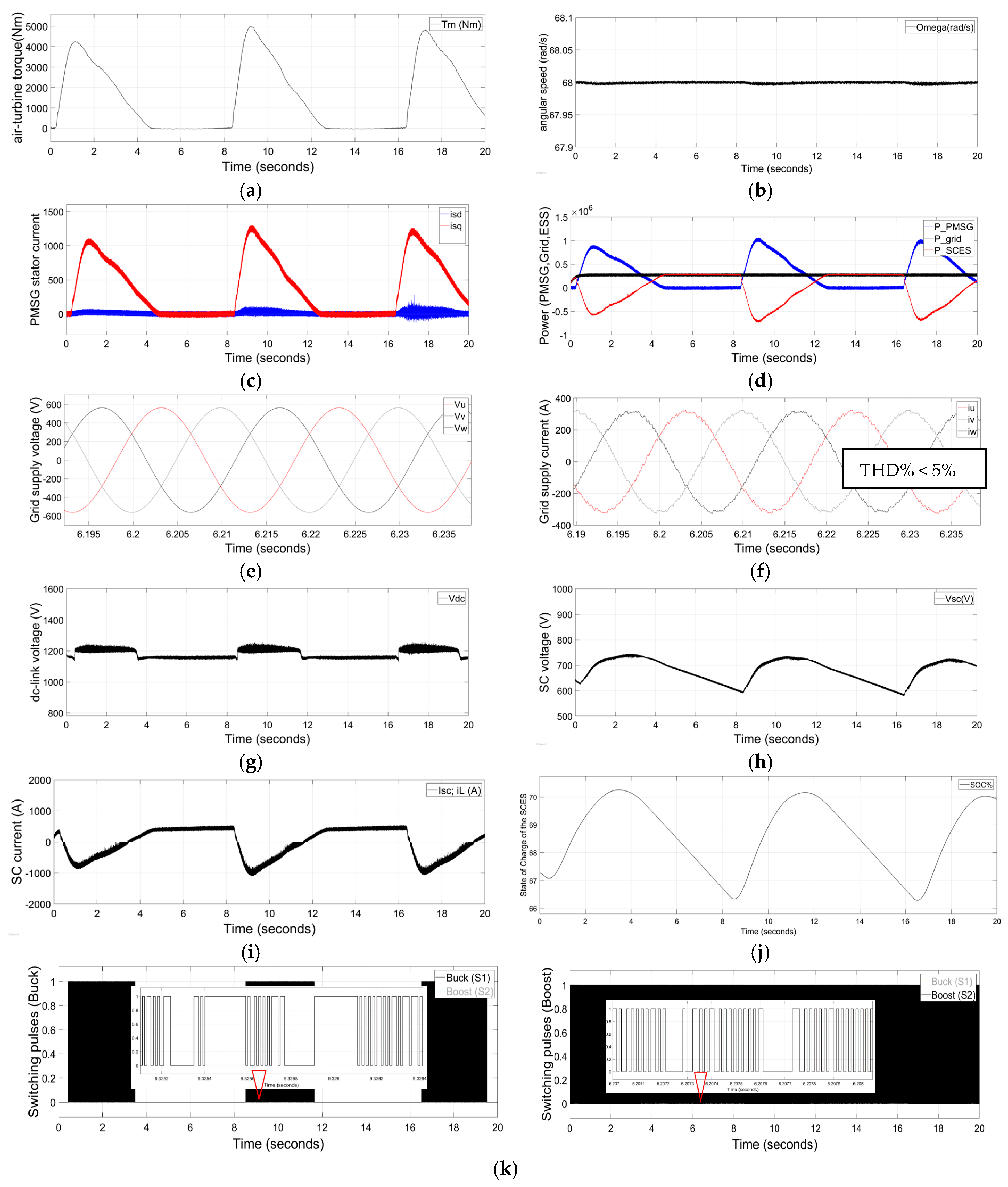
The parameters in Table A1, given in Appendix A.1, were used for the modeling and simulation of the OWC wave energy conversion system and the ESS in MATLAB/Simulink. The modeling of the air turbine, PMSG, back-to-back converter, grid, and filters can be found in [15]. The simulation results shown in Figure 6a–k were used to evaluate the FCS-MPC performance of the dc-dc bidirectional power converter along with the back-to-back converter.
The main control goal in this study was to supply a set, quality grid power output by regulating dc-bus voltage at a safe and effective voltage range while controlling the charging and discharging of the ESS within its technical limits. The other major control objective in this study, as in [15], was to maintain the OWC air turbine speed within the optimum range while extracting large discrete power pulses.
Figure 6a depicts the mechanical torque produced by the unidirectional air turbine at its design speed (650 rpm ≈ 68 rad/s) [6], while the turbine-generator rotor angular speed is shown in Figure 6b. As evident in this figure, the rotational speed of the air turbine is regulated to be within the optimum region throughout the simulation. This confirms that the turbine speed is kept at its control objective throughout the simulation regardless of the significant variation in extracted power (0–1 MW). Figure 6c depicts the PMSG stator current in the dq reference frame. The d-axis current is maintained closer to zero while the q-axis current varies in proportion to the torque input. This q-axis current is directly proportional to the active power drawn from the PMSG, which also varies with the extracted power as shown in Figure 6d.
Figure 6d also illustrates the grid power and SCES power. The PMSG power and SCES power waveforms confirm that the FCS-MPC of the dc-dc bidirectional converter successfully controls the power exchange between the SCES and dc-link. The grid power is maintained at its reference throughout the simulation. This is achieved by the charging and discharging the supercapacitor, compensating the generated and demand power differences. The grid voltage and grid current are shown in Figure 6e,f, respectively. The total harmonic distortion (THD) of the grid’s three-phase current is less than 5% for this simulation, which allows the OWC to be integrated to the grid [40]. Figure 6g depicts the dc-link voltage, which is kept almost constant at 1200 V with more than 90% accuracy. This waveform confirms that the dc-link voltage is controlled successfully by the proposed MPC of the dc-dc bidirectional converter, adhering to the constraints. Also, according to the results, when the generated power is less than the grid power, the dc-link voltage is maintained below its set voltage by discharging the SCES, and when the generated power is more than the grid power, the dc-link voltage is maintained almost at its set level while charging the SCES. Figure 6h–j illustrates the SCES’s voltage, current, and SOC, respectively. These figures confirm that the FCS-MPC and simple PMSs are capable of directing the buck and boost operation of the bidirectional converter while adhering to the ESS’s technical limits, such as maximum discharge current, maximum charging current, SCES maximum voltage, cut-off voltage, minimum SOC, maximum SOC, and so forth. The dc-dc bidirectional converter, buck and boost operations, and switching pulses are shown in Figure 6k and confirm the proposed control strategy of the bidirectional dc-dc converter controlling the switching between the buck and boost modes, depending on the supply-demand power difference. The expanded figures show how the duty cycles change in the buck and boost modes.
6. Conclusions
This paper can be considered as the preliminary study that looks into a grid-connected OWC unidirectional air turbine generator with an SCES system. The air turbine generator is integrated into the grid using a back-to-back power converter, as in authors’ previous work. This study applies and connects a commercially available, affordable-type supercapacitor to the dc-link with a dc-dc bidirectional converter. This approach confirms the smooth and quality power delivery to the grid by absorbing the large discrete power pulses generated by the PMSG. FCS-MPC is applied to the controller of the bidirectional dc-dc converter to direct charging and discharging of the SCES to maintain the dc-link voltage at the set voltage range, directly controlling the inductor current. The control algorithm used for this power converter does not consider the SCES parameters other than the SCES’s voltage. Therefore, it can be used for any type of ESS with minor adjustments. This also allows the authors to carry out further research using either a Li-ion battery or supercapacitor ESS using the same converter control algorithm. Moreover, the power management strategy is addressed to maintain the SOC of the SCES at predefined technical limitations to increase the ESS’s lifespan. The simulation results were analyzed to confirm the feasibility of the applied MPC strategy. The rotational speed of the turbine generator was almost constant at 68rad/sec, while the THD of the output current was below the grid code requirement of 5% during the entire simulation. These results confirm that the proposed MPC strategy for the controllers is capable of maintaining a quality power supply, adhering to the grid code irrespective of the significant intermittencies present in the extracted power from the waves under varying sea conditions.
Although these results obtained from the software simulation are very promising, further investigations and implementations are in progress for lab-scale hardware experimental validations and the development of an adaptive system against parameter variations.
Author Contributions
G.R. and S.J. conceived of and designed the simulator model and analyzed the data; G.R. wrote the paper; S.J., A.F., and M.N. critically reviewed the paper.
Acknowledgments
The authors thank Wave Swell Energy for providing the parameters to use in the simulation studies.
Conflicts of Interest
The authors declare no conflict of interest.
Appendix A
Appendix A.1. System Parameters Used in the Design

Table A1.
System parameters used in the design.
| PMSG | Rated Power | 2 MW |
| Rated rotate speed | 650 rpm | |
| Rated Voltage | 690 VAC | |
| Rated current | 1673.5 A | |
| Number of pole pairs | 4 | |
| Resistance (Rs) | 0.0024 Ω | |
| Inductances (Ld = Lq) | 0.3552 mH (line-phase) | |
| Magnetic flux | 0.666 Wb | |
| Inertia (J) | 2 kgm2 | |
| Grid side Filter | Inductance | 1.6 mH |
| Resistance | 0.01 Ω | |
| Rated charge/discharge currents | 1500 A | |
| Grid | Voltage | 690 Vrms |
| Frequency | 50 Hz | |
| Generator Side Filter | Inductance | 1 mH |
| Resistance | 0.01 Ω | |
| DC-link | Total power | 265 kW |
| DC-link voltage (Vdc) | 1200 V | |
| DC-link current (Idc_max) | 1000 A | |
| Supercapacitor | Capacitance (Csc) (83F; 21 in series; 4 parallel loop) | 15.8 F |
| Resistance (Rsc) | 52.5 mΩ | |
| Voltage Initial (Vinitial) (Csc_nominal: 48 V each) | 650 V | |
| Reference Values | Active Power | 265 kW |
| Reactive Power | 0 | |
| Other | Sample time (s) (Rec./Inv./bidirectional) | 10−4/10−4/7 × 10−5 |
| Simulator run time | 20 s |
Appendix A.2. FCS-MPC for Rectifier
function [Sa,Sb,Sc] = fcn(vdc, is, vs, Ө, ωm, Tm)
% Sa,Sb,Sc: Switching signals for the rectifier; vdc: dc-link voltage; is: PMSG current; vS: PMSG phase voltage; Ө: angle of the reference frame (rad/s); ωm: PMSG rotational speed (rad/s); Tm: air-turbine torque.
Ts = 1e−4; % Sample time (s)
% Load parameters
Rs = 0.01; % Stator Resistance + generator side filter resistance (Ω)
Ls = 1e−3; % stator Inductance + Generator side filter inductance (H)
np = 4; %pole pairs
flux = 0.66; % PMSG flux
J = 2; % inertia
ωm_ref = 68; % 68 rad/s
K = 2e−4; % constant
id_ref = 0;
% Switching states
states = [0 0 0;1 0 0;1 1 0;0 1 0;0 1 1;0 0 1;1 0 1;1 1 1];
states2 = [0 0 0; 2 −1 −1; 1 1 −2; −1 2 −1; −2 1 1; −1 −1 2; 1 −2 1; 0 0 0];
vAFE = vdc*states2/3;
% is is derived from phase currents ia, ib and ic
%ia (k+1) = ik1a
%ib (k+1) = ik1b
%ic (k+1) = ik1c
g_opt = 1e10;
x_opt = 1;
for i = 1:8
% Current prediction at instant k+1
ik1a = (1 − Rs* Ts /Ls)*is(1) − Ts /Ls*(vAFE (i,1) − vs(1));
ik1b = (1 − Rs* Ts /Ls)*is (2) − Ts /Ls*(vAFE (i,2) − vs (2));
ik1c = (1 − Rs* Ts /Ls)*is(3) − Ts /Ls*(vAFE (i,3) − vs (3));
% abc to dq conversion
idk1 =2*(ik1a*sin(Ө) + ik1b*sin(Ө − 2*pi/3) + ik1c*sin(Ө + 2*pi/3))/3;
iqk1 =2*(ik1a*cos(Ө) + ik1b*cos(Ө − 2*pi/3) + ik1c*cos(Ө + 2*pi/3))/3;
Te = 1.5*flux* np*iqk1; % Predicted torque
ωmk1 = ωm + Ts *(Tm − Te)/J; % Predicted speed
g = abs(ωm_ref − ωmk1) + K*abs(id_ref − idk1); % Cost function
if (g < g_opt) % Minimize cost function
g_opt = g;
x_opt = i;
end
end
% Output switching states
Sa = states(x_opt,1);
Sb = states(x_opt,2);
Sc = states(x_opt,3);
Appendix A.3. FCS-MPC for Inverter
function [Su,Sv,Sw] = fcn(vdc, Pref, ig, vg)
% Su,Sv,Sw: Switching signals for the inverter; Pref: Active and reactive power reference; vdc: dc-link voltage; ig: grid current; vS: grid phase voltage.
Ts = 1e−4; % Sample time (s)
% Load parameters
Rg = 0.01; % grid side filter resistance (Ω)
Lg = 1e−3; % grid side filter inductance (H)
% Voltage vectors
v0 = 0 + 1j*0;
v1 = 2/3*vdc + 1j*0;
v2 = 1/3*vdc + 1j*sqrt(3)/3*vdc;
v3 = −1/3*vdc + 1j*sqrt(3)/3*vdc;
v4 = −2/3*vdc + 1j*0;
v5 = −1/3*vdc − 1j*sqrt(3)/3*vdc;
v6 = 1/3*vdc − 1j*sqrt(3)/3*vdc;
v7 = 0 + 1j*0;
v = [v0 v1 v2 v3 v4 v5 v6 v7];
% Switching states
states = [0 0 0; 1 0 0; 1 1 0; 0 1 0; 0 1 1; 0 0 1; 1 0 1; 1 1 1];
g_opt = 1e10;
x_opt = 1;
% Read power reference inputs at sampling instant k
Pkref = Pref(1) + 1j*Pref(2);
Pref(1) = 265e3; % grid active power reference (W)
Pref(2) = 0; % grid reactive power reference
% Read current and voltage measurements at sampling instant k
ik = (0.8165*(ig(1) − ig(2)/2 − ig(3)/2)) + 1j*(0.7071*(ig(2) − ig(3)));
vk = (0.8165*(vg(1) − vg(2)/2 − vg(3)/2)) + 1j*(0.7071*(vg(2) − vg(3)));
for i = 1:8
% Current and power prediction at instant k+1
ik1 = (1 − Rg* Ts /Lg)*ik + Ts /Lg*(v(i) − vk);
Pk1 = (real(vk)*real(ik1) + imag(vk)*imag(ik1)) + 1j*(imag(vk)*real(ik1) − real(vk)*imag(ik1));
% Cost function
g = (abs(real(Pkref − Pk1)))*(abs(real(Pkref − Pk1))) + (abs(imag(Pkref − Pk1)))*(abs(imag(Pkref − Pk1)));
% Selection of the optimal value
if (g < g_opt)
g_opt = g;
x_opt = i;
end
end
% Output switching states
Su = states(x_opt,1);
Sv = states(x_opt,2);
Sw = states(x_opt,3);
Appendix A.4. FCS-MPC for dc-dc Bidirectional Converter of Energy Storage
function [S1, S2] = fcn(vdc, vESS, iL, vdcref, PPMSG, Pg)
% S1: buck switching; S2: Boost switching; vdc: dc-link voltage; vESS: energy storage system voltage; iL: inductor current; vdcref: dc-link reference (1200V); PPMSG: air-turbine generator power; Pgrid: grid power.
Ts = 1e−5; % Sample time (s)
L = 5e−4; % Inductance (H)
vdcref = 1200; % dc-link voltage reference (V)
g_opt = 1e10;
x_opt1 = 0;
x_opt2 = 0;
%Boost converter
if (vdc < vdcref) % Energy deficit condition. Boost converter should be selected
iLref = ((Pg − PPMSG)+(vdcref − vdc)*100)/vESS; % Inductor current reference. “100” is an arbitrary gain to speed up.
for i = 0:1
iLk1 = iL + (vESS + ((i −1)*vdc))* Ts /L; %Predicted inductor current
g =abs(iLref − iLk1); %Cost function for the boost converter
if (g < g_opt) %Search for the switching state which minimizes the cost function
g_opt = g;
x_opt1 = i;
x_opt2 = 0;
end
end
end
%Buck converter
if (vdc > vdcref) % Energy excess condition. Buck converter should be selected
iLref = ((Pg − PPMSG)+(vdcref − vdc)*100)/vESS; % Inductor current reference. “100” is an arbitrary gain to speed up.
for i = 0:1
iLk1 = iL - (i*vdc − vESS)* Ts /L; %Inductor current prediction
g =abs(iLref − iLk1); %Cost function for the buck converter
if (g < g_opt) %Search for the switching state which minimizes the cost function
g_opt = g;
x_opt1 = 0;
x_opt2 = i;
end
end
end
% Set output signals
S1 = x_opt2;
S2 = x_opt1;
References
- Aderinto, T.; Li, H. Ocean Wave Energy Converters: Status and Challenges. Energies 2018, 11. [Google Scholar] [CrossRef]
- Hannon, M.; Griffiths, J.; Vantoch-Wood, A.; Carcas, M.; Bradley, S.; Boud, R.; Wyatt, S. World Energy Resources; Marine Energy 2016; World Energy Council; World Energy Resources: London, UK, 2016. [Google Scholar]
- Carson, L.; Bradshaw, M.; Jaques, L. Australian Energy Resource Assessment 2014, 2nd ed.; Commonwealth of Australia (Geoscience Australia): Canberra, Australia, 2014.
- Carson, L.; Bradshaw, M.; Jaques, L.; Che, N.; Ball, A. Australian Energy Resource Assessment 2010; Commonwealth of Australia (Geoscience Australia): Canberra, Australia, 2010.
- Hughes, M.G.; Heap, A.D. National-scale wave energy resource assessment for Australia. Renew. Energy 2009, 35, 1783–1791. [Google Scholar] [CrossRef]
- Wave Swell Energy. Sustainable Elecricity from the Ocean. Available online: http://waveswellenergy.com.au/ (accessed on 27 March 2017).
- Australian Maritime College. Successful Ocean Wave Energy Converter Testing Leads to Commercialisation. Available online: http://www.amc.edu.au/about-amc/news-and-events/news-items/successful-tidal-turbine-testing-leads-to-commercialisation/ (accessed on 11 May 2017).
- PerAero Turbine Design LLC. Turbine Design Report for Wave Swell Energy Ltd.; PerAero Turbine Design LLC: Bonita Springs, FL, USA, 2017. [Google Scholar]
- Hamidi, S.A.; Lonel, D.M.; Nasiri, A. Modeling and Management of Batteries and Ultracapacitor for Renewable Energy Support in Electric Power Systems—An Overview. Electr. Power Compon. Syst. 2017, 43, 1434–1452. [Google Scholar] [CrossRef]
- Rajapakse, G.; Jayasinghe, S.G.; Fleming, A.; Shahnia, F. Model Predictive Control-based Power take-off Control of an Oscillating Water Column Wave Energy Conversion System. In Proceedings of the 2017 International Conference on Substantial Energy Engineering (ICSEE 2017), Perth, Australia, 12–14 June 2017. [Google Scholar]
- Maercos, V.M.M.; Martinez, M.A.G.; Gonzalez, F.B.; Montero, M.I.M. A Grid Connected Photovoltic Inverter with Battery-Supercapacitor Hybrid Energy Storage. Sensors 2017, 17. [Google Scholar] [CrossRef]
- Murray, D.; Multon, A.J.B.; Ahmed, H.B. Electrical energy storage systems. In Electrical Design for Ocean Wave and Tidal Energy Systems; Alcorn, R., O’Sullivan, V., Eds.; The Institution of Engineering and Technology (IET): Herts, UK, 2013. [Google Scholar]
- Kim, J.; Suharto, Y.; Daim, T.U. Evaluation of Electrical Energy Storage (EES) technologies for renewable energy: A case from the US Pacific Northwest. J. Energy Storage 2017, 11, 25–54. [Google Scholar] [CrossRef]
- Murray, D.B.; Hayes, J.G.; Egan, M.G.; O’Sullivan, D.L. Supercapacitor Testing for Power Smoothing in a Variable Speed Offshore Wave Energy Converter. IEEE J. Ocean. Eng. 2011, 37, 301–308. [Google Scholar] [CrossRef]
- Rajapakse, G.; Jayasinghe, S.G.; Negnevitsky, M.; Fleming, A. A Model Predictive Control-Based Power Converter System for Oscillating Water Column Wave Energy Converters. Energies 2017, 10, 1631. [Google Scholar] [CrossRef]
- Hamidi, A.; Weber, L.; Nasiri, A. EV Chargeing Station Integrating Renewable Energy and Second Life Battery. In Proceedings of the International Conference on Renewable Energy Research and Application, Madrid, Spain, 20–23 October 2013. [Google Scholar]
- Wu, F.; Zhang, X.; Ju, P. Application of the battery energy storage in wave energy conversion system. In Proceedings of the International Conference on Sustainable Generation and supply (SUPERGEN’09), Nanjing, China, 6–7 April 2009. [Google Scholar]
- Rodriguez, J.; Kazmierkowski, M.P.; Espinoza, J.R.; Zanchetta, P.; Abu-Rub, H.; Young, H.A.; Rojas, C.A. State of the Art of Finite Control Set Model Predictive Control in Power Electronics. IEEE Trans. Ind. Inform. 2013, 9, 1003–1016. [Google Scholar] [CrossRef]
- Vazquez, S.; Leon, J.I.; Franquelo, L.G.; Rodriguez, J.; Young, H.A.; Marquez, A.; Zanchetta, P. Model Predictive Control: A Review of Its Applications in Power Electronics. IEEE Ind. Electron. Mag. 2014, 8, 16–31. [Google Scholar] [CrossRef] [Green Version]
- Pirooz, A.; Noroozian, R. Model Predictive Control of Classic Bidirectional DC-DC Converter for Battery Applications. In Proceedings of the 7th Power Electronics, Drive Systems & Technologies Conference (PEDSTC 2016), Iran University of Science and Technology, Tehran, Iran, 16–18 February 2016. [Google Scholar]
- Ceballos, S.; Rea, J.; Robles, E.; Lopez, I.; Pou, J.; O’Sullivan, D.L. Control strategies for combining local energy storage with wells turbine oscillating water column devices. Renew. Energy 2015, 83, 1097–1107. [Google Scholar] [CrossRef]
- Ceballos, S.; Rea, J.; Lopez, I.; Pou, J.; Robles, E.; O’Sullivan, D.L. Efficiency optimization in low inertia wells turbine oscillating water column devices. IEEE Trans. Energy Convers. 2013, 28, 553–564. [Google Scholar] [CrossRef]
- Li, W.; Joos, G.; Abbey, C. A parallel bidirectional DC/DC converter topology for energy storage systems in wind applications. In Proceedings of the Conference Record of the 2007 IEEE Industry Applications Conference, New Orleans, LA, USA, 2007; pp. 171–185. [Google Scholar]
- Zou, Y.; Cheng, K.W.E. A Vertical Flux-Switching Permanent Magnet Based Oscillating Wave Power Generator with Energy Storage. Energies 2017, 10, 887. [Google Scholar] [CrossRef]
- Maxwell Technologies. Maxwell_Supercapacitor_48v_DN 1009365 13; Maxwell Technologies: San Diego, CA, USA, 2017. [Google Scholar]
- Thounthong, P.; Sikkabut, S.; Mungporn, P.; Mobarakeh, N.; Pierfederici, S.; Davat, B. Nonlinear Control Algorithm of Supercapacitor/Li-Ion Battery Energy Storage Devices for Fuel Cell Vehicle Applications. In Proceedings of the Mecatronics-2014, Tokyo, Japan, 27–29 November 2014. [Google Scholar]
- Hannan, M.A.; Lipu, M.S.H.; Hussain, A.; Mohamed, A. A review of lithium-ion battery state of charge estimation and management system in electric vehicle applications: Challenges and recommendations. Renew. Sustain. Energy Rev. 2017, 78, 834–854. [Google Scholar] [CrossRef]
- Zhi, L.; Peng, Z.; Zhifu, W.; Qiang, S.; Yinan, R. State of charge estimation for Li-ion battery based on extended Kalman filter. In Proceedings of the 8th International Conference on Applied Energy—ICAE2016, Beijing, China, 8–11 October 2016; pp. 3515–3520. [Google Scholar]
- Bernal, L.E.Z. Characterization of Double-Layer Capacitors for Power Electronics Applications. Master’s Thesis, Electrical and Computer Engineering, University of Toronto, Toronto, ON, Canada, 1997. [Google Scholar]
- Zubieta, L.; Bonert, R. Characterization of Double-Layer Capacitors for Power Electronics Applications. IEEE Trans. Ind. Appl. 2000, 36, 199–205. [Google Scholar] [CrossRef]
- Islam, M.S.; Hossain, M.B.; Hossain, M.N.; Alam, S.B.; Chowdhury, M.E.H. Modeling of a Double-Layer Capacitor with Individual Branch Response. In Proceedings of the World Congress on Engineering and Computer Science 2010, San Francisco, CA, USA, 20–22 October 2010. [Google Scholar]
- Bimbhra, P.S. Generalized Theory of Electrical Machines; Khanna Publishers: Delhi, India, 1992. [Google Scholar]
- Vilathgamuwa, M.; Nayanasiri, D.; Gamini, S.; Hudgins, J. Power Electronics for Photovoltaic Power Systems (Synthesis Lectures on Power Electroncs); Morgan & Claypool Publishers: San Rafael, CA, USA, 2015; ISBN 978-1-62705-775-2. [Google Scholar]
- Abdullah, M.A.; Yatim, A.H.M.; Tan, C.W.; Samosir, A.S. Control of a Bidirectional Converter to Interface Ultracapacitor with Renewable Energy Sources. In Proceedings of the IEEE International Conference on Industrial Technology (ICIT), Cape Town, South Africa, 25–28 February 2013. [Google Scholar]
- Samosir, A.S.; Yatim, A.H.M. Implementation of Dynamic Evolution Control of Bidirectional DC–DC Converter for Interfacing Ultracapacitor Energy Storage to Fuel-Cell System. IEEE Trans. Ind. Electron. 2010, 57, 3468–3473. [Google Scholar] [CrossRef]
- Leuchter, J. Bi-Directional DC-DC Converters for Battery Buffers with Supercapacitor. In Energy Storage in the Emerging Era of Smart Grids; InTech: Rijeka, Croatia, 2011; p. 492. ISBN 978-953-307-269-2. [Google Scholar]
- Hart, D.W. Power Electronics; McGraw-Hill: New York, NY, USA, 2011. [Google Scholar]
- Yaramasu, V.N.R. Predictive control of Multilevel Converters for MegaWatt Wind Energy Conversion Systems. Ph.D. Thesis, Electrical and Computer Engineering, Ryerson University, Toronto, ON, Canada, 2014. [Google Scholar]
- Brka, A.; Kothapalli, G.; Abdeli, Y.M. Predictive power management strategies for stand-alonehydrogen systems: Lab-scale validation. Int. J. Hydrog. Energy Publ. 2015, 40, 9907–9916. [Google Scholar] [CrossRef]
- Langella, R.; Testa, A. IEEE Recommended Practice and Requirements for Harmonic Control in Electric Power System; University of Campania “Luigi Vanvitelli”: Caserta, Italy, 2014. [Google Scholar]
Figure 1.
Schematic diagram of the grid connected oscillating water column (OWC) wave energy conversion (WEC) system with a supercapacitor energy storage system.
Figure 1.
Schematic diagram of the grid connected oscillating water column (OWC) wave energy conversion (WEC) system with a supercapacitor energy storage system.
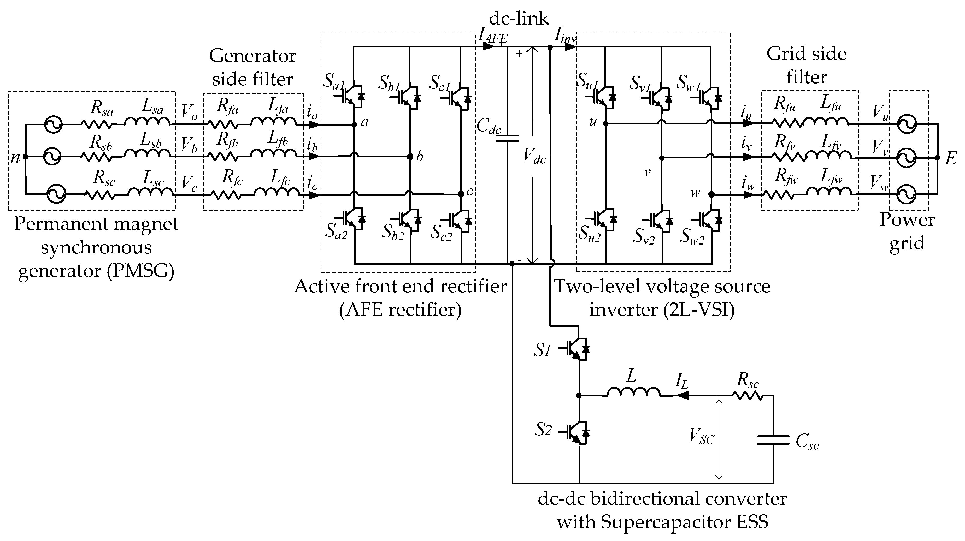
Figure 2.
Schematic diagram of the proposed controllers for the grid integration of an OWC unidirectional air turbine generator with a hybrid energy storage system (HESS).
Figure 2.
Schematic diagram of the proposed controllers for the grid integration of an OWC unidirectional air turbine generator with a hybrid energy storage system (HESS).

Figure 3.
(a) Behavior of supercapacitor charge and its current with time; and (b) charge/discharge curves of supercapacitor and Li-ion battery.
Figure 3.
(a) Behavior of supercapacitor charge and its current with time; and (b) charge/discharge curves of supercapacitor and Li-ion battery.

Figure 4.
Half bridge (HB) dc-dc bidirectional converter of supercapacitor energy storage (SCES); (a) dc-link with electrical power converters; (b) buck mode operation of the bidirectional dc-dc converter; and (c) boost mode operation of the bidirectional dc-dc converter.
Figure 4.
Half bridge (HB) dc-dc bidirectional converter of supercapacitor energy storage (SCES); (a) dc-link with electrical power converters; (b) buck mode operation of the bidirectional dc-dc converter; and (c) boost mode operation of the bidirectional dc-dc converter.

Figure 5.
The flow chart of model predictive control (MPC) algorithm of a dc-dc bidirectional converter.
Figure 5.
The flow chart of model predictive control (MPC) algorithm of a dc-dc bidirectional converter.
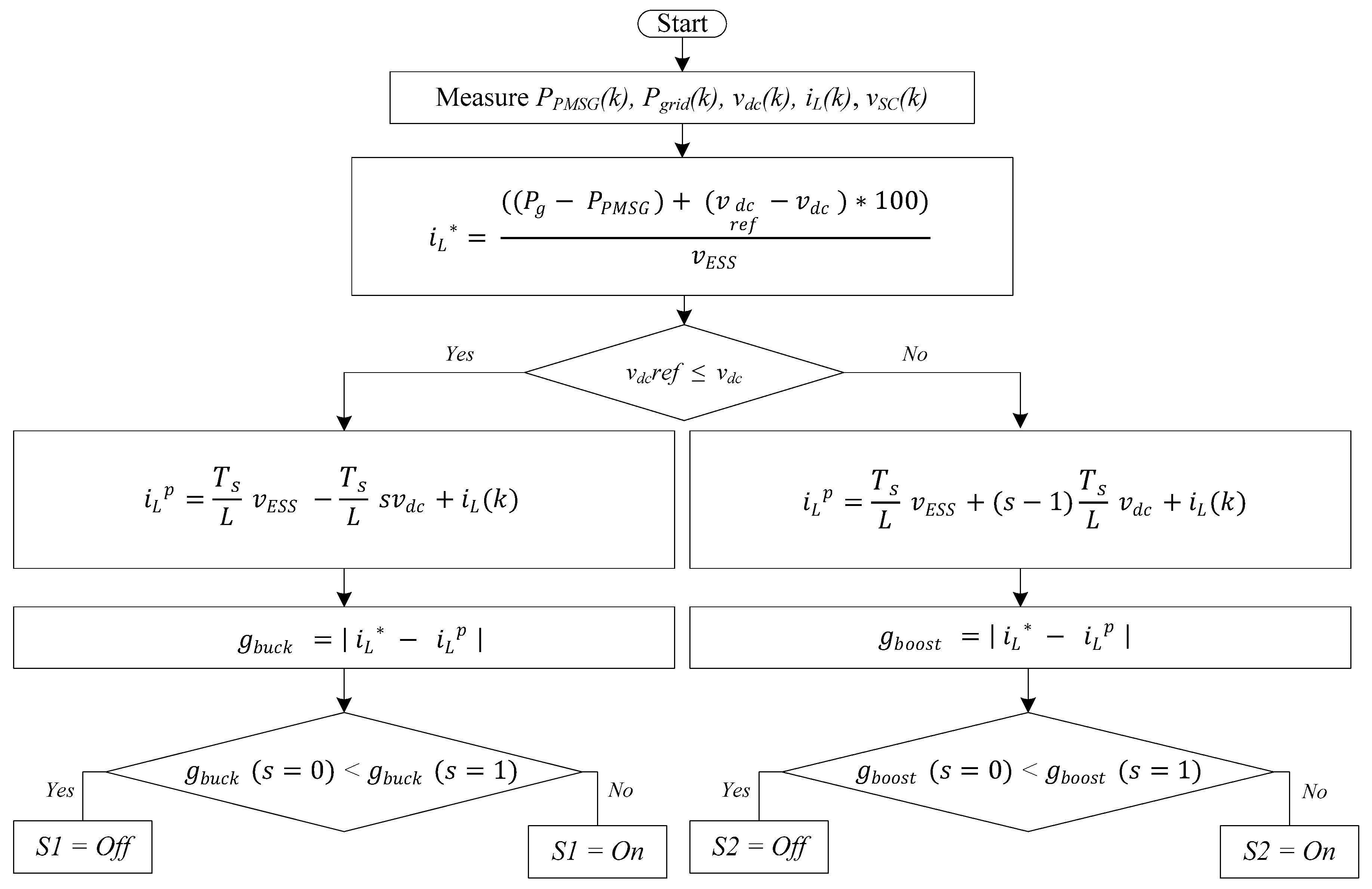
Figure 6.
The simulation results of the OWC grid-integrated system with SCES; (a) mechanical torque profile (Tm); (b) generator rotor angular speed (ωm); (c) PMSG stator current in dq frame (isd and isq); (d) power (PMSG, grid, SCES); (e) grid voltage (vg); (f) grid current (ig); (g) dc-link voltage (vdc); (h) supercapacitor voltage (vsc); (i) inductor current (iL); (j) state of charge of the SCES (SOC); and (k) dc-dc bidirectional converter switching pulses.

© 2018 by the authors. Licensee MDPI, Basel, Switzerland. This article is an open access article distributed under the terms and conditions of the Creative Commons Attribution (CC BY) license (http://creativecommons.org/licenses/by/4.0/).
Share and Cite
MDPI and ACS Style
Rajapakse, G.; Jayasinghe, S.; Fleming, A.; Negnevitsky, M. Grid Integration and Power Smoothing of an Oscillating Water Column Wave Energy Converter. Energies 2018, 11, 1871. https://doi.org/10.3390/en11071871
AMA Style
Rajapakse G, Jayasinghe S, Fleming A, Negnevitsky M. Grid Integration and Power Smoothing of an Oscillating Water Column Wave Energy Converter. Energies. 2018; 11(7):1871. https://doi.org/10.3390/en11071871
Chicago/Turabian StyleRajapakse, Gimara, Shantha Jayasinghe, Alan Fleming, and Michael Negnevitsky. 2018. "Grid Integration and Power Smoothing of an Oscillating Water Column Wave Energy Converter" Energies 11, no. 7: 1871. https://doi.org/10.3390/en11071871
Note that from the first issue of 2016, this journal uses article numbers instead of page numbers. See further details here.