Macroscopic and Microscopic Spray Characteristics of Diesel and Gasoline in a Constant Volume Chamber


1
Department of Mechanical Engineering, Dong-A University, Busan 49315, Korea
2
School of Automotive and Mechanical Design Engineering, Youngsan University, Yangsan 50510, Korea
3
Department of Mechanical Design Engineering, Pukyong National University, Busan 48547, Korea
4
Division of Mechanical Convergence Engineering, Silla University, Busan 46958, Korea
*
Author to whom correspondence should be addressed.
Energies 2018, 11(8), 2056; https://doi.org/10.3390/en11082056
Submission received: 30 June 2018
/
Revised: 27 July 2018
/
Accepted: 6 August 2018
/
Published: 8 August 2018
(This article belongs to the Special Issue Recent Advances in Internal Combustion Engines Operation and Emissions)
Abstract
:The aim of this study is to investigate the spray characteristics of diesel and gasoline under various ambient conditions. Ambient conditions were simulated, ranging from atmospheric conditions to high pressure and temperature conditions such as those inside a combustion chamber of an internal combustion engine. Spray tip penetration and spray cross-sectional area were calculated in liquid and vapor spray development. In addition, initial spray development and end of injection near nozzle were visualized microscopically, to study spray atomization characteristics. Three injection pressures of 50 MPa, 100 MPa, and 150 MPa were tested. The ambient temperature was varied from 300 K to 950 K, and the ambient density was maintained between 1 kg/m3 and 20 kg/m3. Gasoline and diesel exhibited similar liquid penetration and spray cross-sectional area at every ambient density condition under non-evaporation. As the ambient temperature increased, liquid penetration length and spray area of both fuels’ spray were shortened and decreased by fuel evaporation near the spray boundary. However, the two fuels were characterized by different slopes in the decrement trend of spray area as the ambient temperature increased. The decrement slope trend coincided considerably with the distillation curve characteristics of the two fuels. Vapor spray boundary of gasoline and diesel was particularly similar, despite the different amount of fuel evaporation. It was assumed that the outer spray boundary of gasoline and diesel is always similar when using the same injector and injection conditions. In microscopic spray visualization, gasoline spray displayed a more unstable and asymmetric spray shape, with more dispersed and distributed fuel ligaments during initial spray development. Large amounts of fuel vapor cloud were observed near the nozzle at the end of the injection process with gasoline. Some amounts of this vapor cloud were attributed to the evaporation of residual fuel in the nozzle sac.
1. Introduction
Compression ignition (CI) engines can achieve a high thermal efficiency owing to the high compression ratio and lack of throttling losses [1]. However, high nitrogen oxides (NOx) and particulate matter (PM) emissions from diesel engine have led to research and development of clean and efficient combustion technology. Therefore, many advanced combustion strategies have been widely researched, such as the homogeneous charge compression ignition (HCCI), premixed charge compression ignition (PCCI), and partial premixed charge compression ignition (PPCCI) [2,3,4]. These combustion strategies are normally realized by improved mixing between fuel and air, compared with conventional combustion. The well-mixed fuel/air mixture can suppress the formation of NOx and PM emissions. However, there have been many challenges to realize this concept with diesel, as commercial diesel has poor volatility due to the high boiling point range [5]. Diesel also tends to have a short mixing time due to the easy auto-ignition characteristics [6]. Recently, gasoline-like fuels with superior vaporization characteristics and high-octane numbers have been widely tested in CI engines [6,7,8,9,10]. It was demonstrated that gasoline has a long ignition delay, compared with diesel [6]. Gasoline is advantageous in achieving very high thermal efficiency under high load conditions with properly modulated combustion phasing [8]. Furthermore, very low NOx and PM emissions were emitted from well mixed fuel/air mixture, due to the enhanced mixing characteristics [9].
Spray development process has very important role for combustion quality in CI engines [11,12,13,14,15]. Therefore, it has been extensively studied numerically and experimentally. Spray development process involves many stages such as nozzle flow, cavitation, liquid disintegration, ligament formation, atomization, air entrainment, evaporation and so on [11,12,13]. Each stage has influences on next stage. Every stage occurred under highly transient nature. Spray development process should be investigated from 2 point of view which are microscopic and macroscopic analysis. Microscopic investigation can reveal many valuable information about spray development near nozzle which are initial spray development, spray atomization, fully developed spray formation and after-end of injection [16,17,18]. Initial spray atomization characteristics are attributed to air entrainment and interfacial shearing instabilities between spray and ambient air [19,20]. Sprays are atomized by stages, liquid column to liquid ligaments, liquid ligaments to fuel droplets and to smaller droplets. Related researches have been carried out by combination of microscope and high power lighting [16,17,18,19].
Macroscopic investigation for spray development can reveal the information about macroscopic spray behavior such as spray tip penetration, spray angle and spray area and so on [11,12,14,15,21,22,23]. It is absolutely important for understanding total spray development process.
Spray development process is highly affected by the physical properties of fuel. There are many important properties such as density, viscosity, surface tension and so on [12,19,20]. Gasoline-like fuels have significantly different physical properties from diesel fuel, so comprehensive research for spray development is necessary. Payri et al. examined the liquid penetration length of gasoline and diesel sprays under non-evaporating conditions [14]. They reported that the gasoline and diesel sprays exhibited very similar spray behaviors for the liquid penetration length and spray cone angle. Kim et al. investigated gasoline spray by visualization in engine cylinder and found that gasoline spray showed significantly shorter spray penetration length and spray cone angle than diesel spray [24,25]. Kim et al. also investigated the spray and combustion characteristics of gasoline and diesel under three combustion regimes such as HCCI, PCCI and conventional combustion [26]. They found that gasoline showed much faster evaporation than diesel under all combustion regimes. For the combustion, gasoline showed longer ignition delay and liftoff length due to the high resistivity to autoignition. Most of microscopic spray investigations are carried out by using optical long-distance microscopy [20,21,22,23]. Because of highly transient spray nature, special diagnostic considerations must be implemented such as short duration of light pulses and exposure time. Back illumination imaging of the shadow by the spray has been used to analyze the spray distribution characteristics efficiently [20,21,22,23]. Many microscopy imaging studies have researched on spray behavior such as spray penetration rate and spray angle during start and end of injection [20,22,27]. Researchers also reported that higher injection pressure and ambient gas density cause the higher interfacial instability due to the higher disturbances. Crua et al. compared fossil diesel, rapeseed oil methyl esters (RME) and kerosene fuel for initial spray development process under non evaporating condition [20]. They reported that kerosene, which had lower viscosity and surface tension showed more ligaments than other fuels. It implied that primary atomization is highly affected by the stabilizing force of viscosity and surface tension which impacts on the formation of ligaments, droplets and instabilities.
However there are few studies on comparisons of the spray behavior of gasoline and diesel under wide range of ambient conditions in the open literature, even though author’s previous works were focused on the spray and combustion as the introductory research of gasoline compression ignition (CI) engines [24,25,26]. This study aimed to compare the spray behavior of gasoline and diesel comprehensively under wide range of ambient conditions. Investigations on the spray development process include the injection rate measurement, macroscopic liquid/vapor spray analysis and microscopic visualization of near nozzle spray behavior. Through the investigations, difference of gasoline spray compared with diesel spray could be understood physically in depth. Injection rate were measured to investigate the mass flow rate through the nozzle and injector dynamics when using the gasoline and diesel. Spray penetration length and spray cross-section area of liquid and vapor spray were estimated under wide variation of ambient density and temperature conditions. Initial spray development and end of injection process were visualized near nozzle to investigate initial spray break up and injection termination process in microscopic spray investigation.
2. Experimental Conditions and Setup
2.1. High Pressure/Temperature Constant Volume Chamber
A constant volume chamber that can simulate high pressure and temperature conditions, such as those in a real engine, was used to explore spray characteristics under a wide range of ambient densities and temperatures. The constant volume chamber setup consists of subsystems such as mixture preparation part, chamber body and intake/exhaust lines. Figure 1 shows the diagram of chamber system. Four gases, namely C2H2, H2, O2, and N2, were introduced in pre-mixing chamber with a pre-estimated proportion to produce target ambient oxygen concentration after complete pre-combustion.
In this study, target oxygen concentration was 0% for all experiments to observe only spray not combustion. Under the assumption of complete combustion, four gases were introduced into the chamber with stoichiometric ratio as shown in Table 1. Hydrogen was used to help complete combustion because of its fast flame velocity. Molar mass of premixed gas mixture was 28.68 g/mol. The chamber wall was preheated to 473 K. After triggering spark, the chamber pressure was increased and decreased owing to heat loss through the chamber wall. The in-chamber pressure was recorded using a piezo-electric pressure transducer (6141B, Kistler, Winterthur, Switzerland) at 100 kHz.
2.2. Optical Setup and Image Processing for Spray Visualization
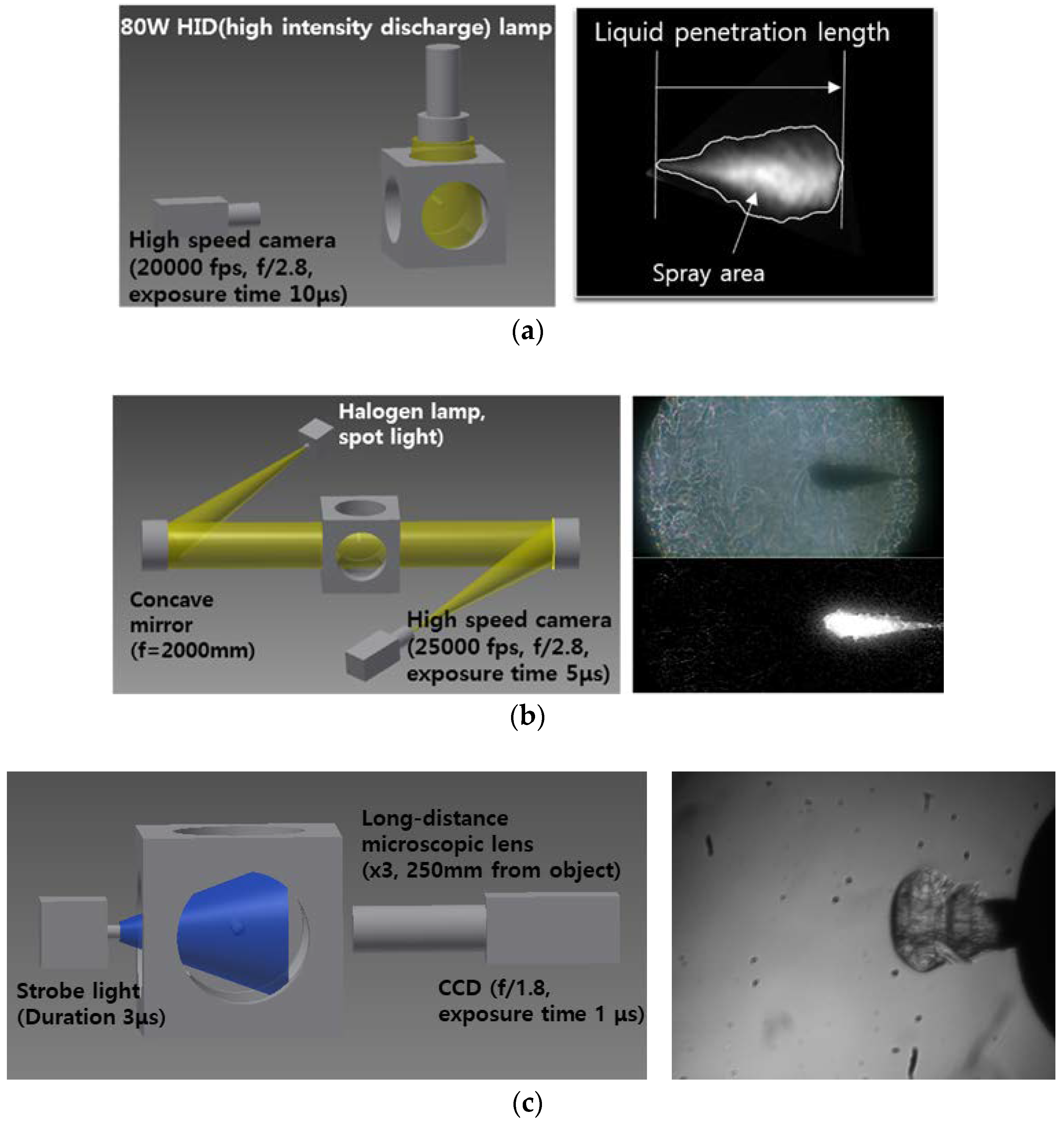
Schematic diagrams of the optical diagnostics setup are shown, with sample images, in Figure 2. Mie-scattering technique was used to capture the liquid spray development process. Spray development was captured by high speed camera (V7.1, Phantom, NJ, USA) at 20 kHz with exposure time of 10 μs. High intensity discharge (HID) lamp was used for illumination of spray as shown in Figure 2a. The recorded images contained mie-scattered light from fuel spray and other objects such as nozzle tip. To figure out the spray only from the image, background image was subtracted by fuel spray image. The pixel with more than 5% of the maximum brightness was defined as the spray region. Spray penetration length was defined as the distance from the nozzle tip to the farthest spray region from the nozzle tip. Spray cross sectional area was calculated by the integration of pixels of spray region. Optical setup and image processing used for mie-scattering in this study were same as reference [26].
Vapor spray development was captured using shadowgraph technique as shown in Figure 2b. A halogen lamp and two concave mirrors were used and images were acquired at 25 kHz with exposure time of 6 μs. Microscopic visualization near the nozzle was performed by charge coupled device camera (Sensicam, PCO AG, Kelheim, Germany) and long distance microscopic lenses. For the illumination, spark light (MVS-2061-CE96, EG&G Opto-electronics, Salem, MA, USA) was located at opposite side of CCD camera facing each other as shown in Figure 2c. Short exposure time of 1 μs was used to capture the distinct boundary of fast spray development process. Image processing for the analysis of vapor spray development was also explained in detail in Kim et al. [26]. The boundary of vapor region in fuel spray could be distinguished by different refractive index originated from the density gradient between fuel spray and ambient. It is difficult to figure out the spray boundary in shadowgraph image due to the shade in the background image at high temperature and density conditions. This shade was attributed to the high density gradient from the temperature difference. It could be processed to binary image to figure out the fuel spray boundary by subtraction of the image of fuel spray from the background image which is acquired before the start of fuel injection. Vapor boundary of fuel spray could be achieved by the processing the image as shown in figure. As same as the way to process mie-scattering images, pixel of more than 5% of the maximum brightness was defined as the spray region.
2.3. Injection Systems and Fuel Properties
Injection systems were used as same as in the reference [26]. Common rail-injection systems were used for both diesel and gasoline. Injector specifications are listed in Table 2. A single hole diesel solenoid injector (CRI 2.2, Bosch, Stuttgart, Germany) was used. The nozzle orifice diameter was 354 μm. The properties of the gasoline and diesel used in the experiments are also listed in Table 2. Density and distillation temperature ranges are significantly different for gasoline and diesel.
Gasoline has a lower density and viscosity than diesel. The distillation temperature range is also significantly lower fuel injection parameters are controlled by controllers, which are pressure controller (ZB-1200, Zenobalti Co., Daejeon, Korea), and injector driver (IDU 5000B, Zenobalti Co., Daejeon, Korea).
2.4. Experimental Conditions
The experimental conditions are listed in Table 3. Injection pressure was controlled within 50 MPa to 150 MPa. Injection command duration was set at 900 μs. As stated in Section 2.1, ambient conditions were implemented by the complete combustion of premixed gas. The ambient density and temperature were varied to investigate the effect of ambient conditions on spray development process. In all the tests, the ambient oxygen concentration was set to 0%, to avoid combustion of fuel spray. Three ambient densities and five temperatures were tested. The ambient density was varied from 1 kg/m3 to 20 kg/m3. The ambient temperature was varied from 300 K to 950 K.
3. Results and Discussion
3.1. Mass Flow Rate Characteristics of Gasoline and Diesel
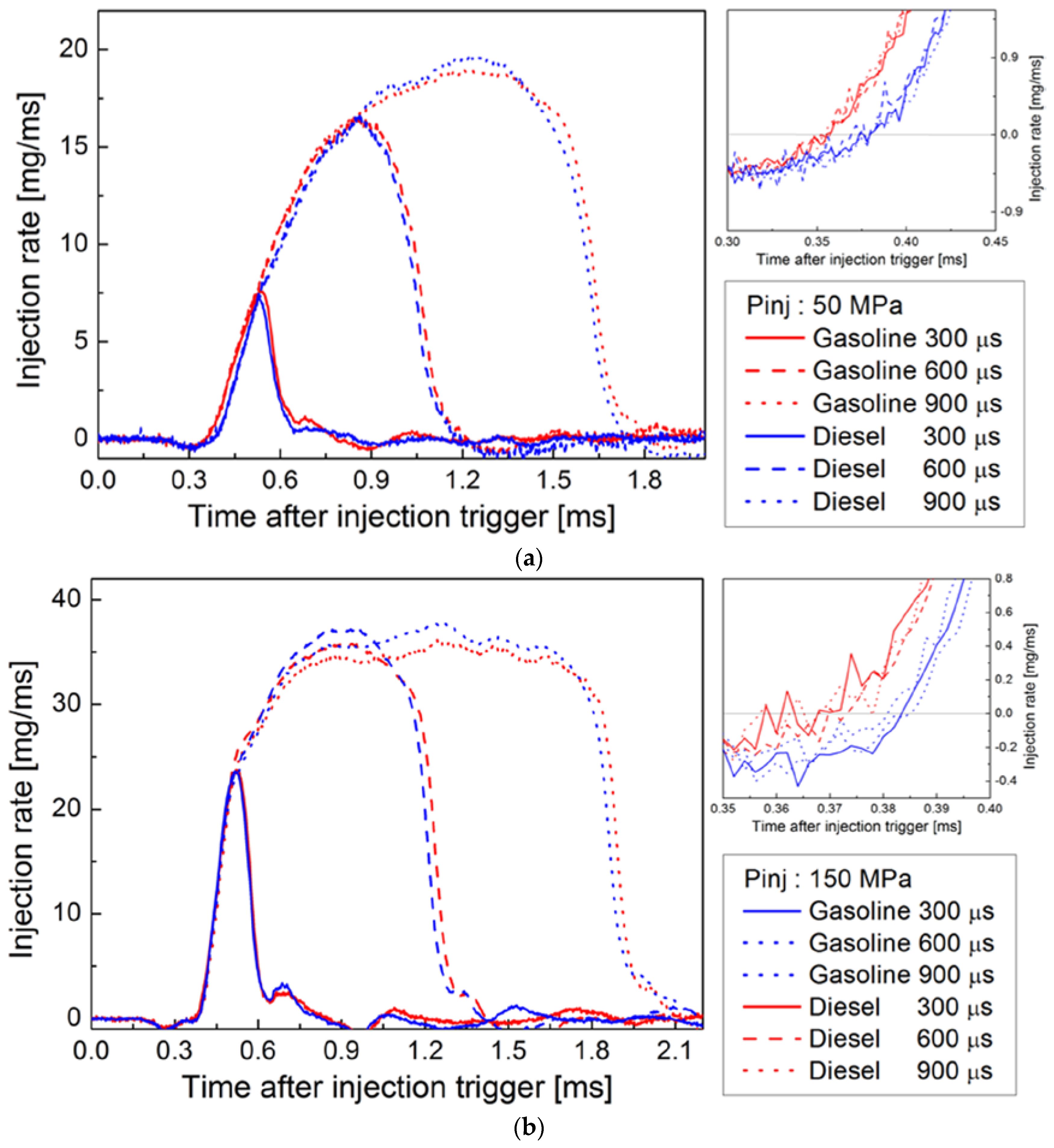
Prior to the spray visualization study, injection rates were measured to compare mass flow rate characteristics of the two fuels when using the same injector. Figure 3 shows the injection rate of gasoline and diesel at injection pressures of 50 MPa and 150 MPa. Injection rates were measured with the Bosch tube method. Very similar injection rates were observed, in terms of injection delay and mass flow rate peak, for both gasoline and diesel. However, on closer examination, different fine characteristics were observed between the two fuels. Injection duration, which indicate duration from injection start to end, was slightly longer for gasoline than for diesel. The start of injection for gasoline was earlier than that for diesel by about 20 μs at an injection pressure of 50 MPa, and about 10 μs at an injection pressure of 150 MPa. As injection pressure decreased, the time difference was becoming longer. In addition, the end of injection for gasoline was later than that for diesel. These differences should be attributed to the different fuel properties and primarily to fuel viscosity. Lower viscosity of gasoline will enable the fuel to pass fast through partially opened nozzle orifice at the start of injection period due to the smaller friction force of fuel against the nozzle orifice wall. In the same manner, at the end of injection, gasoline was flowing very easily through the partially opened nozzle orifice. Therefore, injection time for gasoline was longer duration than for diesel.
However, for the peak mass flow rate when nozzle is fully opened, diesel showed higher value than gasoline. This is attributed to diesel’s higher density.
3.2. Macroscopic Spray Characteristics of Gasoline and Diesel
3.2.1. Liquid Spray Area
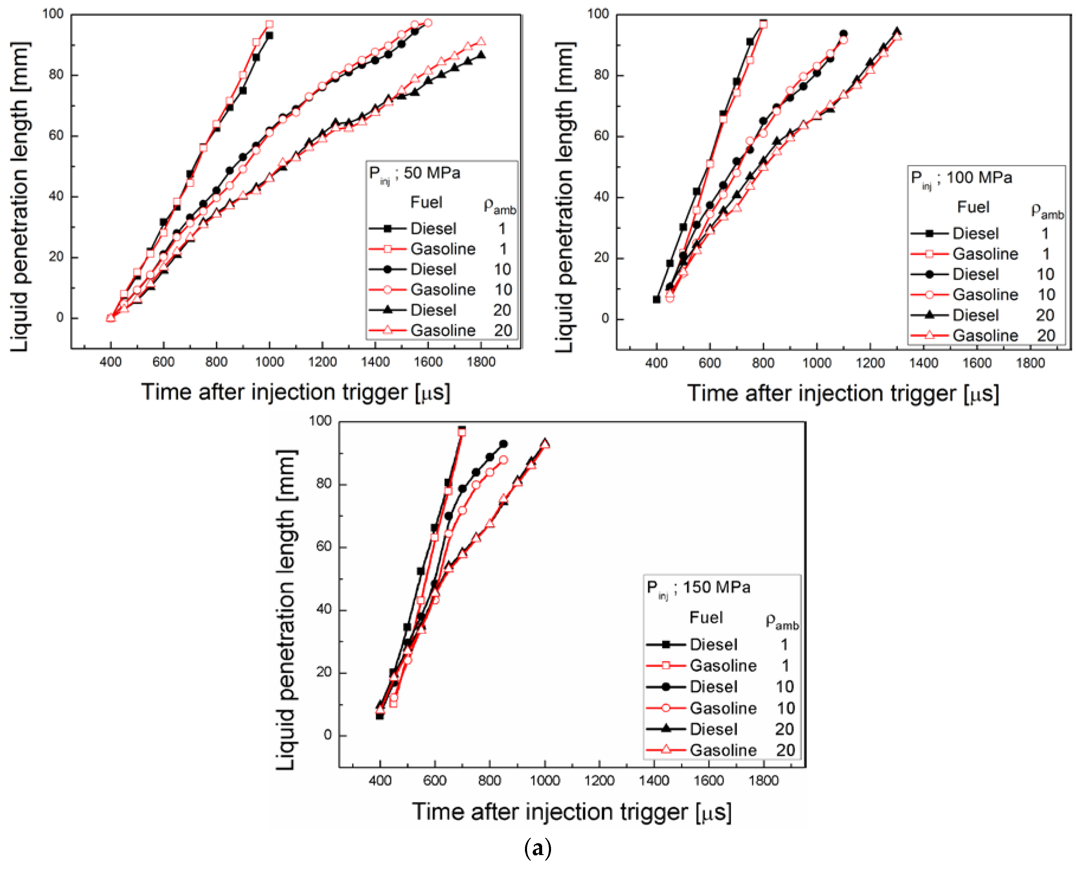
Figure 4 shows the quantitative analysis of liquid penetration length and spray cross-section area of gasoline and diesel with ambient density variation at fixed ambient temperature of 300 K. As shown in Figure 4a, liquid penetration length between diesel and gasoline was quite similar through all ambient density and injection pressures. This similarity of liquid penetration length under non-evaporating condition was also reported by Payri et al. and Kim et al. [14,25]. The rapid decrease of liquid penetration length with ambient density resulted from the spray momentum loss due to the increase of drag force. Momentum loss is proportional to the spray sectional area and spray velocity. Therefore, the narrower spray angle, the smaller drag force, so spray penetration length increases. The result that gasoline and diesel showed similar penetration length indicated that the spray angles of two fuels have no significant difference. Theoretically, the momentum of the spray is determined by the pressure difference between inside nozzle and ambient. Therefore, under the non-evaporating condition, two fuels have similar liquid penetration length in macroscopic view.
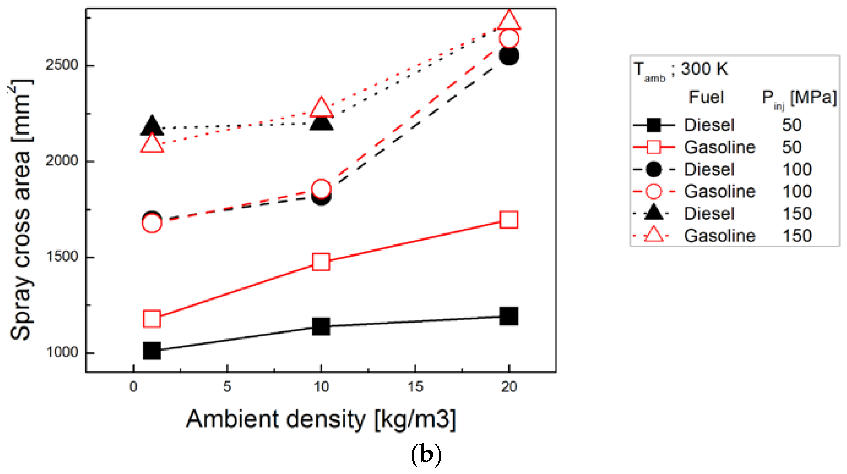
In terms of spray cross-section area, gasoline and diesel spray showed similar absolute area and increasing trend according to increase of ambient density [14,15,24,25]. Higher injection pressure produced larger spray area, mostly due to the increased spray cone angle [28]. When injection pressure and ambient density conditions are low, gasoline spray showed slightly larger spray cross-section area than that of diesel spray. It was attributed by that gasoline spray formed slightly wider spray cone angle by about 5 degree at lower injection pressure condition [29]. This resulted from the gasoline’s lower viscosity characteristic [30]. As stated in injection rate analysis, gasoline spray has higher Reynolds number compared with diesel spray. Higher Reynolds number by five times, due to lower viscosity and density, could cause considerable instability during spray development process. This characteristic contributed to a wider spray cone angle.
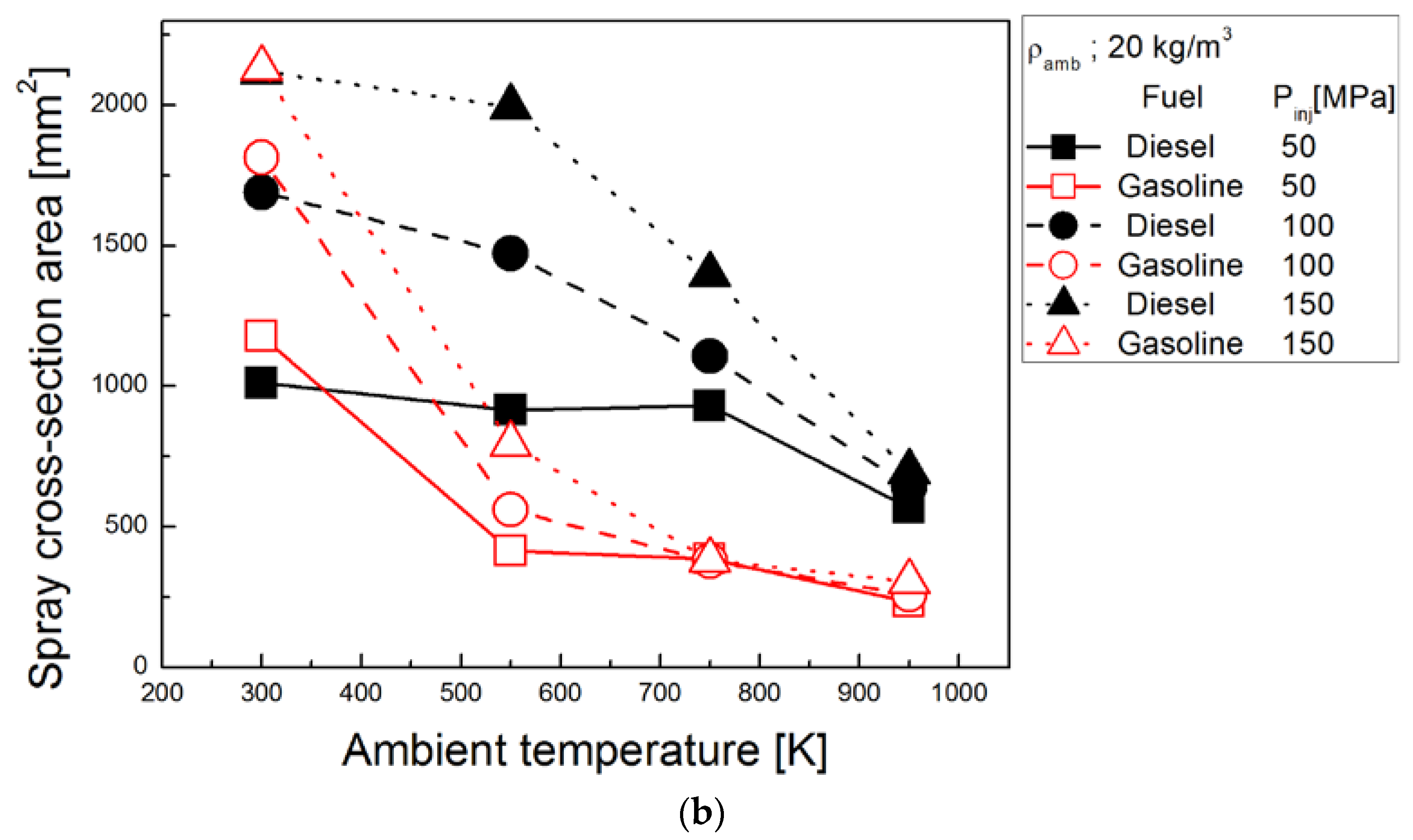
Figure 5a,b show the liquid spray length and spray cone angle of diesel and gasoline with ambient temperature variation. As the ambient temperature increased, significant differences in liquid spray development were observed between gasoline and diesel through all conditions. Maximum liquid penetration length is determined by the balance of the amount of spray propagation and spray evaporation. At the equilibrium penetration length, liquid spray head does not propagate more. Spray head location is fixed with disturbance fluctuation by turbulence. Liquid penetration length was decreased for both fuels as ambient temperature increased due to the vigorous evaporation at the spray head. Gasoline spray showed more significant decrease in penetration. This implies that larger amount of vaporization occurred at gasoline spray compared with diesel which resulted from the lower distillation temperature range of gasoline [26]. It is generally known that liquid penetration length is highly influenced by the fuel density and distillation characteristics. Liquid penetration length is dominantly governed by the T90 regardless of the numbers of fuel component [31]. Gasoline used in this study has lower T90 than diesel by about 200 K. In addition, as observed above, gasoline spray has the possibility of more air entrainment into the fuel spray compared with diesel spray, so evaporation should be promoted further.
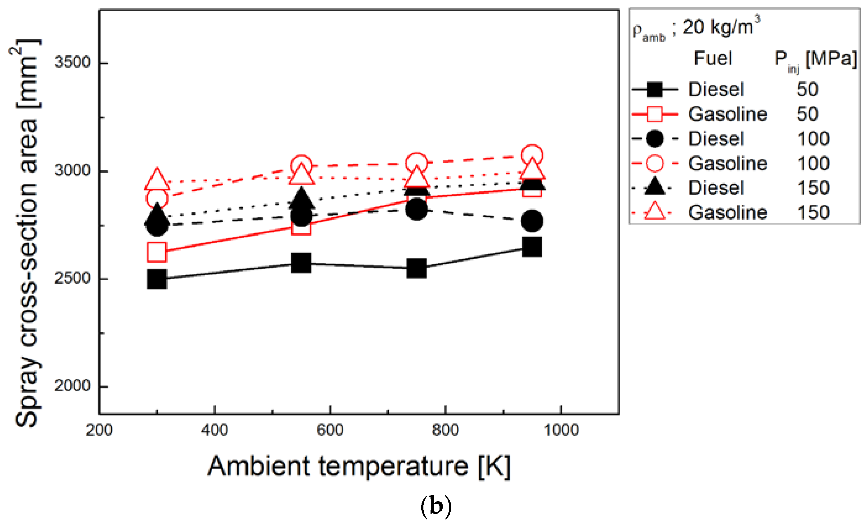
Spray cross-section area also showed similar trends. Gasoline spray has slightly larger spray cross sectional area than diesel spray due to the slightly wider spray angle. Spray cross sectional area was calculated by averaging spray cross sectional area from the point where the injection rate reached the maximum value to the end of injection. Spray cross-section area was also decreased for both gasoline and diesel with increased ambient temperature. However, the slope of decrease according to ambient temperature was quite different between two fuels. Gasoline fuel cross-section area showed significant decrease in range of 300–550 K and then, small decrement was followed in range of 550–950 K. This is attributed to the gasoline’s distillation temperature range. Gasoline used in this study has T90 of 413 K, so the most of fuel spray could be evaporated at ambient temperature of 550 K. Diesel fuel cross-section area experienced fast decrement in range of 550 K to 950 K. As ambient temperature increase further, the spray cross sectional area of gasoline and diesel became similar due to the promoted evaporation. This trend should be attributed to the different distillation temperature curve characteristic of gasoline and diesel as indicated in Table 1.
Fuel spray evaporation behavior follows closely each fuel’s distillation curve. At higher injection pressures, a very significant decrement in spray area was observed at the same temperature range, compared with lower injection pressures. This stems from the enhanced atomization performance by high injection pressure.
3.2.2. Vapor Spray Area
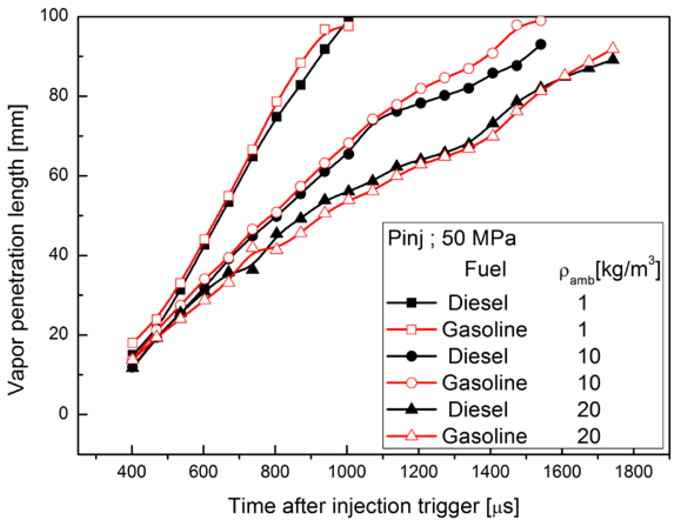
Figure 6a,b show vapor penetration length and spray cross-section area of gasoline and diesel according to ambient density variation. When comparing with vapor penetration length and liquid penetration length, it was observed that there was no significant difference between them. This was attributed to that evaporation rarely occurred under the room temperature condition. Spray cross sectional area was calculated at the point where spray penetration length reached 50 mm, center of the visualization window. Vapor penetration length for both fuels was decreased but spray cross-section area was increased with increase of ambient density. These are attributed to the increased drag force due to high ambient density. There was little difference between gasoline and diesel spray for penetration length and spray area as reported in Reference [26]. When injection pressure was increased, vapor penetration length was increased by the increased spray momentum. Vapor spray area was also increased with increased injection pressure.
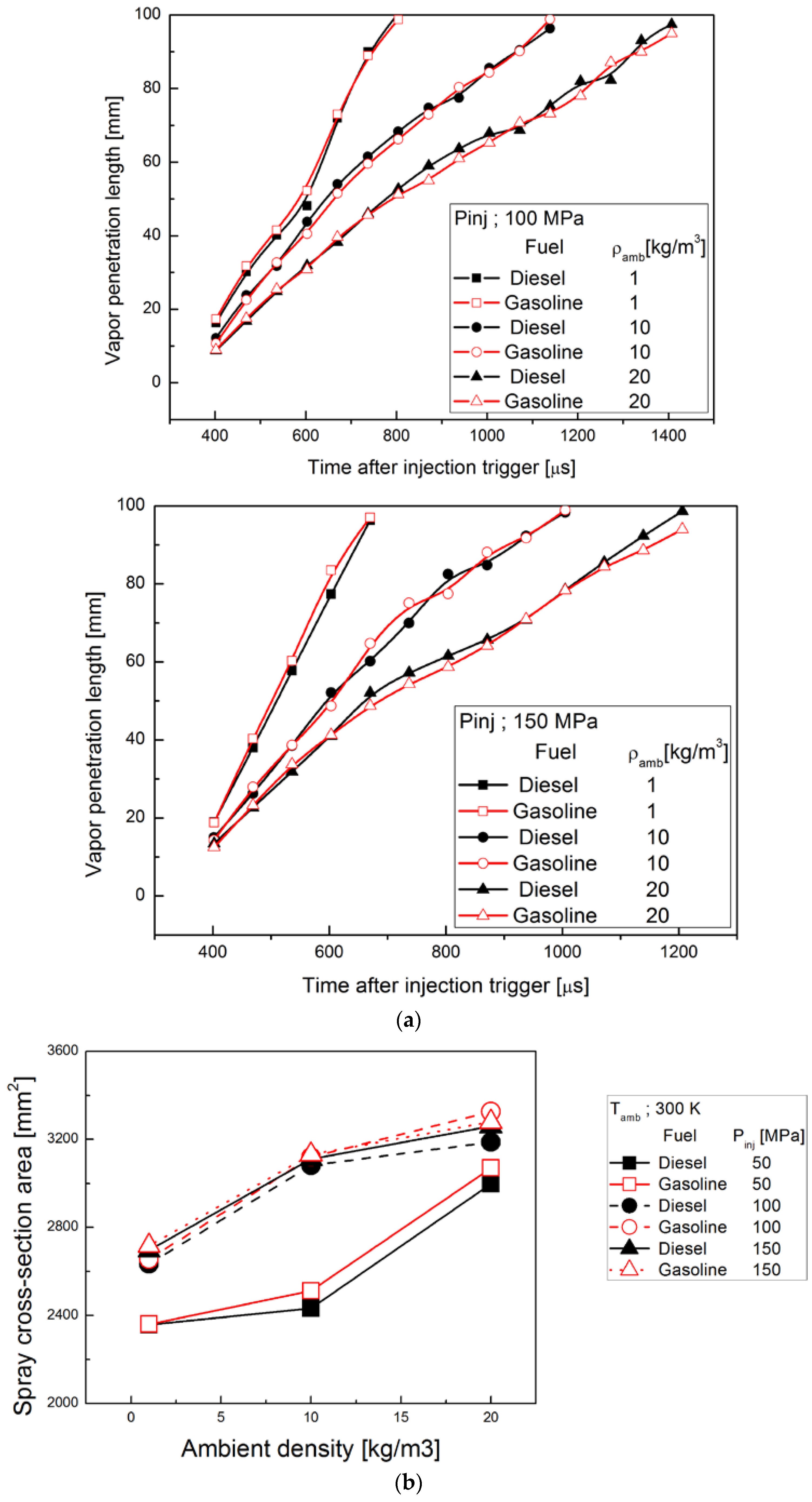
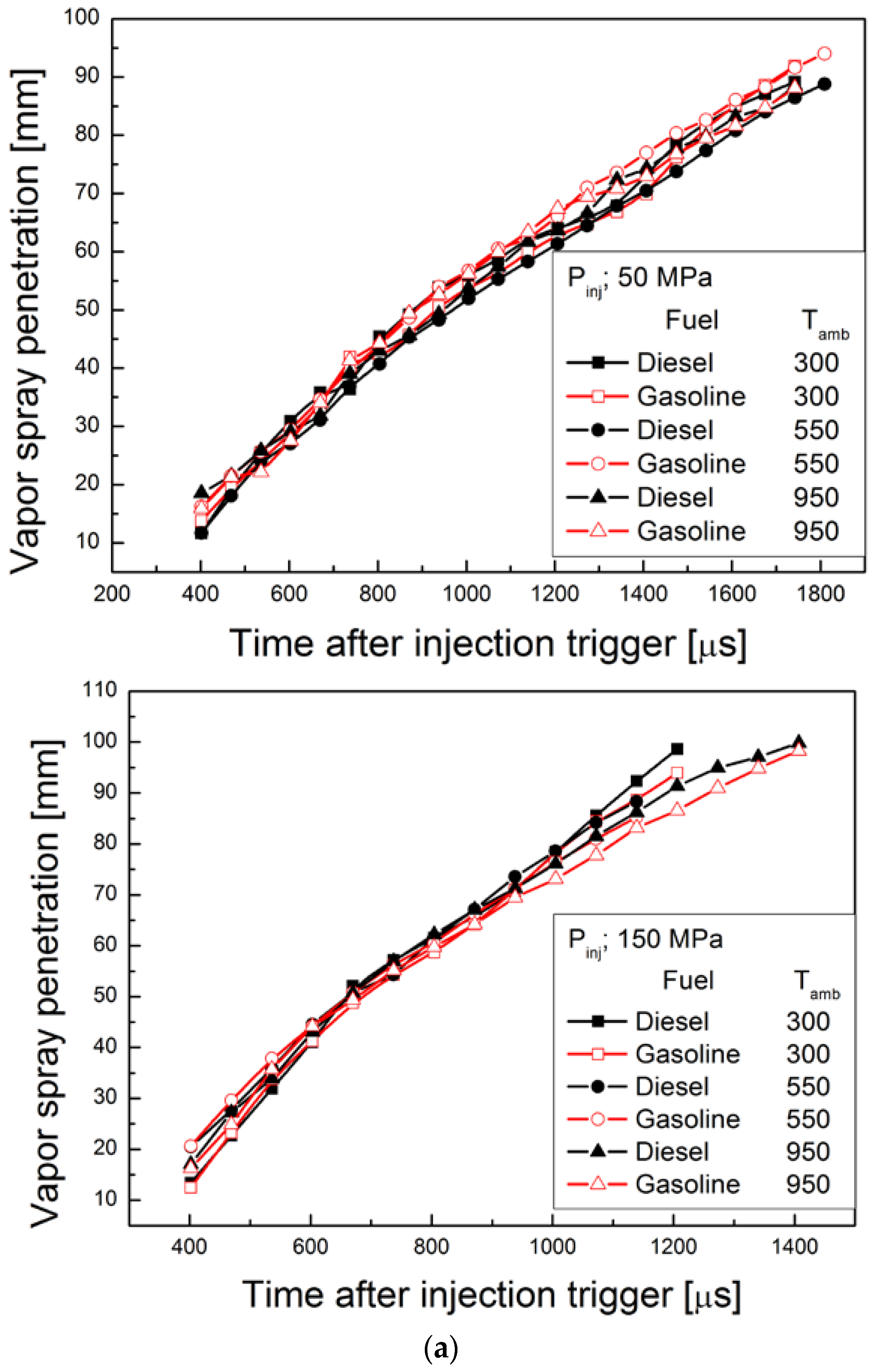
Figure 7a,b shows vapor penetration length and spray cross-section area of gasoline and diesel according to the ambient temperature. Interesting finding was that vapor spray penetration length was always similar regardless of ambient temperature at fixed ambient density. This indicated that the tip penetration of vapor spray was dominantly governed by ambient density not by ambient temperature condition. Vapor spray boundary was very similar between diesel and gasoline at fixed ambient density regardless of ambient temperature. Drag force to spray is the function of multiplying spray area, spray velocity and spray density. With similar spray angle and initial spray momentum, momentum loss was determined by the ambient density. It implies that entire spray boundary of gasoline and diesel is very similar under same ambient conditions and it is not affected by fuel distillation characteristics. Spray cross sectional area of gasoline was slightly bigger than that of diesel due to the slightly wider spray angle of gasoline spray. As stated in Section 3.2.1 liquid spray area, the liquid spray shape was quite different between two fuels due to the volatility.
3.2.3. Microscopic Spray Visualization
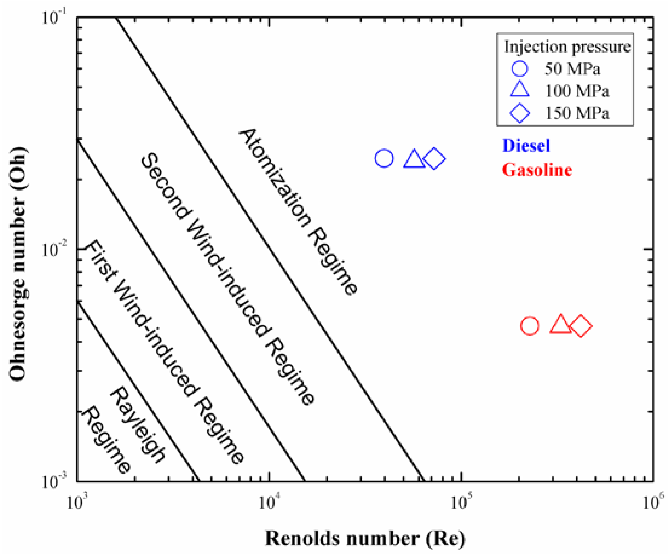
Prior to the analysis on microscopic spray images, Reynolds number and Ohnesorge number were obtained from the injection velocity calculated by the peak injection rate.
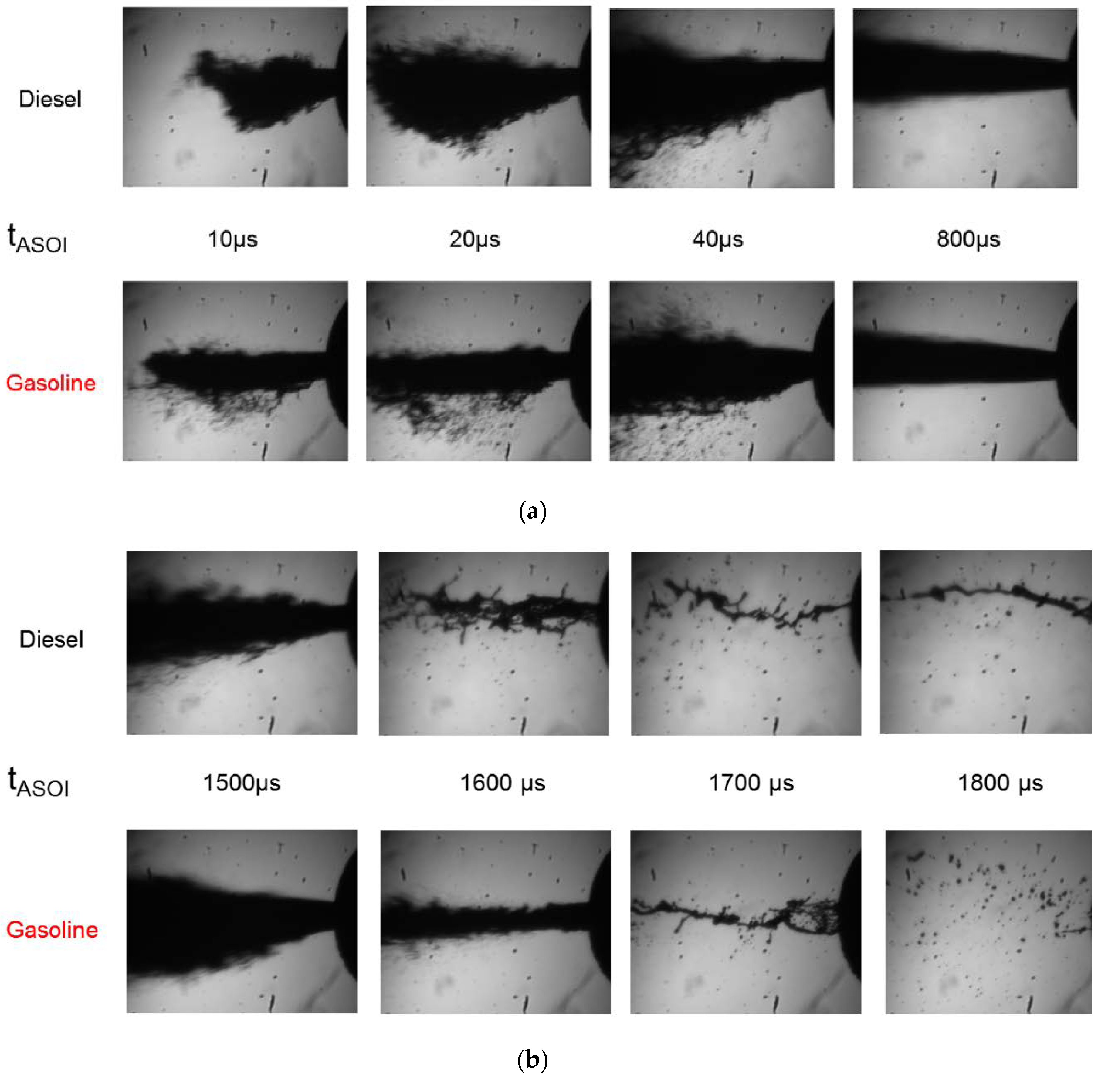
the peak mass flow rate, the injection velocity, and the density of the gas and the liquid fuel, respectively, and σ the dynamic viscosity of the fuel, the surface tension of the fuel. Injection velocity of two fuels were similar as 300~500 m/s according to the injection pressure since peak injection rate of two fuels was similar as shown in Figure 3. However, Re number of gasoline spray was five times higher than diesel because kinematic viscosity of gasoline was one-fifth of that of diesel. High Re indicate the possibility of more turbulence forming around the spray which promote the inflow of ambient air into the spray leading to the atomization of the spray. All experimental conditions were corresponded to the atomization regime as shown in Figure 8. It implied that complete jet disruption from the exit of the nozzle could occur near the nozzle for both fuels. In this study, formation process of initial spray structure and spray distribution after the end of injection near nozzle were observed through the microscopic spray visualization. Microscopic spray visualization was implemented by CCD camera and long distance microscopic lenses to study the process of initial spray development and injection termination near injector nozzle. Figure 9a shows the sequential microscopic spray images near nozzle at ambient density of 1 kg/m3, injection pressure of 50 MPa and ambient temperature of 300 K. Gasoline spray showed higher injection velocity at the early injection process compared with diesel spray. This was attributed to the gasoline’s low viscosity which enables gasoline fuel to pass the nozzle faster with low viscous friction compared with diesel fuel. Liquid ligaments by initial breakup were observed starting at one nozzle diameter distance from the nozzle hole for both fuels. Initial spray shape was more symmetric for diesel spray than gasoline spray. Spray structure for both fuels showed that thick liquid column was located at the center. Liquid ligaments and droplets were detached from the liquid column. Larger amount of detached spray ligaments and big droplets near spray periphery were observed for gasoline spray. Gasoline spray showed more droplets of various sizes detached from the liquid column compared with diesel spray. Diesel spray showed that liquid ligaments were rarely present near the liquid column. These characteristics resulted from the gasoline’s lower viscosity and surface tension characteristics. Higher instability resulted from low surface tension and viscosity of fuel liquid led to the disorder of spray shape and forced vigorous spray break-up [32].
Figure 9b shows the microscopically visualized end of injection process at atmospheric condition and injection pressure of 50 MPa. Spray shape was getting disordered and distracted as injection was finished.
Thick fuel strings were connected, but were soon disconnected, breaking down into short fuel strings and fuel droplets. There was a slight difference in this process, between gasoline and diesel. The former fuel spray displayed thinner and shorter fuel strings and faster break-down into fuel droplets. This should be attributed to gasoline’s lower viscosity characteristic.
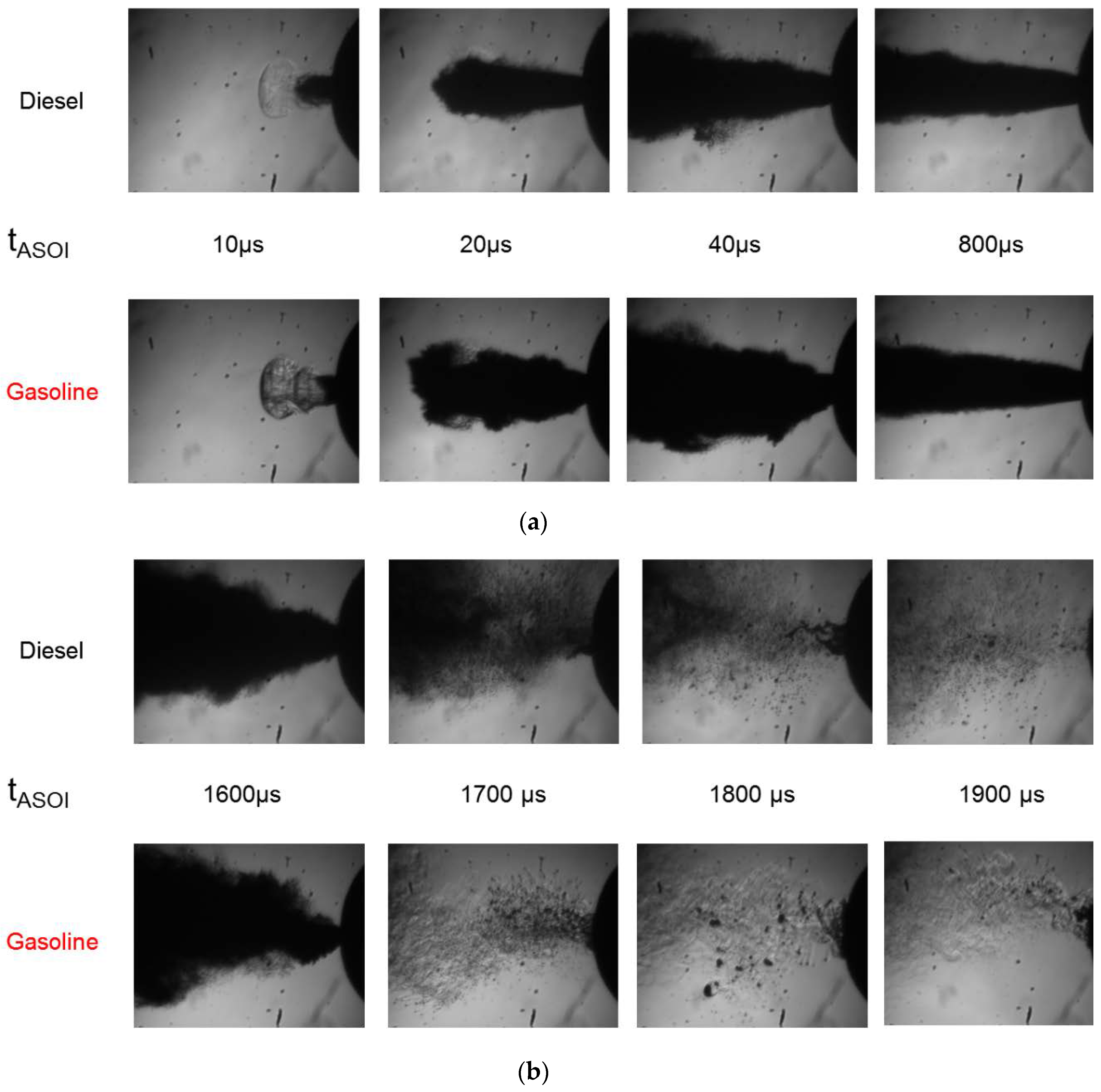
The ambient density and temperature were increased up to 20 kg/m3 and 550 K, respectively, to explore the microscopic spray characteristics under higher ambient density and temperature conditions. Figure 10a,b shows the injection start and injection termination processes at these ambient conditions, respectively. The exiting residual fuel had a transparent appearance at the very early injection start for both fuels. This fuel was from the nozzle sac volume and had been left from the previous injection [32]. Gasoline had a more opaque appearance. It is implied that the boundary between vapor and liquid spray is more unstable and complex, compared with diesel spray [32,33]. As fuel spray penetrates, gasoline spray displayed a wavy spray shape and asymmetric structure, resulting from vigorous mixing with the surrounding air. This should be attributed to the instability of spray boundary due to the low surface tension and viscosity.
As shown, gasoline spray has more dispersed boundary shape and larger spray volume before reaching fully developed state which indicates that the density of spray volume is lower for gasoline spray than diesel spray.
In Figure 10b, the microscopic spray captured at the end of injection is shown, at an ambient density of 20 kg/m3 and the ambient temperature of 550 K. Spray shape of both fuels gets disordered as injection finishes. On the contrary, thick fuel strings were not found in room temperature conditions. Most of the fuel spray instantly disintegrated and split into fuel droplets of various sizes. There was no noticeable difference in droplet size between gasoline and diesel spray. However, it was very interesting that a large thick fuel cloud was observed near nozzle only in gasoline spray. This should be fuel droplet dribbled from nozzle sac [13]. The exiting fuel from the nozzle sac volume formed a rich mixture due to the insufficient mixing with the ambient air by the low momentum. Gasoline-like fuels could exhibit this behavior easily because that type of fuel is easily vaporized. In a direct combustion visualization from author’s previous research, a luminous flame was observed after the end of combustion, with higher luminosity in gasoline combustion than that of diesel combustion [25]. This luminous flame was regarded as a soot incandescence signal from the rich mixture by fuel vaporized from the nozzle sac. An important source of hydrocarbon (HC) emissions in CI engine could be attributed to this region [12,34,35]. Therefore, the rich mixture due to large amount of vaporized fuel from nozzle sac could be one of the evidences for generally higher HC emissions in GDICI engines. It is recommended that nozzle sac volume should be designed to have small volume to prevent the evaporation of residual fuel.
4. Conclusions
Fuel spray visualization in a constant volume chamber was performed, to understand the fuel spray development process of gasoline and diesel using commercial diesel injector in terms of macroscopic and microscopic spray characteristics. Various ambient conditions were considered, with a temperature variation between 300 K and 950 K and an ambient density variation from 1 kg/m3 to 20 kg/m3. Three injection pressures of 50, 100 and 150 MPa, were used. Spray tip penetration length and cross-section area were estimated and compared for liquid and vapor spray. Microscopic spray visualization near nozzle was also carried out to investigate the initial spray development and end of injection.
- Injection rate of two fuels were similar macroscopically but injection delay, peak mass flow rate and real injection duration showed meaningful difference which were attributed to the difference of fuel properties in density and kinematic viscosity.
- Liquid spray development was generally similar between diesel and gasoline at room temperature condition. Gasoline spray exhibited slightly wider spray dispersion with higher spray angle by 1–5 degree, compared with diesel spray. Spray penetration for both fuels is decreased due to the evaporation at the tip of fuel spray with increasing ambient temperature. Gasoline spray exhibited a more rapid decrease than diesel, which stems from more vigorous evaporation. The slope of decrement in spray cross-section area, according to the ambient temperature, closely coincided with the distillation temperature curve of each fuel.
- The vapor spray outer boundary was similar between diesel and gasoline, at the same ambient density, regardless of the ambient temperature. It is estimated that diesel and gasoline have similar outer spray boundary in any combustion chamber if same injection conditions are given.
- Both fuels’ spray were corresponded to the atomization regime. Initial spray breakup occurs at the same distance of one nozzle hole diameter from nozzle orifice exit for spray of both fuels. Gasoline spray exhibited a more unstable and asymmetric spray shape, with more dispersed and distributed fuel ligaments during initial spray development. Both gasoline and diesel spray displayed disintegration of fuel spray into several fuel strings and splitting into fuel droplets at the end of injection process. When the ambient density and temperature increased, fuel strings are hardly observed but many fuel droplets with various sizes are observed. A large amount of fuel vapor cloud manifested near nozzle only in gasoline spray after the end of injection. These vapor cloud came from evaporation of residual fuel of previous injection in nozzle sac. It might also come from attached fuel droplets on nozzle orifice wall. They could be important source of high HC and soot emissions in GDICI (gasoline direct injection compression ignition) engines.
Author Contributions
M.-Y.L. played a leading role in writing the paper as a first author. K.-H.K. is the corresponding author and designed the paper. G.-S.L. and C.-J.K. are co-author and helped to write the part of the results and discussions in the article. J.-H.S. is the co-author and analyzed the data obtained by experiment. All authors have read and approved the final manuscript.
Funding
This work was supported by the National Research Foundation of Korea (NRF) grant funded by the Korea government (MSIT) (No. 2017R1C1B5017435) and by Basic Science Research Program through the National Research Foundation of Korea (NRF) funded by the Ministry of Education (2016R1D1A1B03935822).
Conflicts of Interest
The authors declare no conflict of interest.
Nomenclature
| Pinj | injection pressure (MPa) |
| Tamb | ambient temperature (K) |
| ρamb | ambient density (kg/m3) |
References
- Dec, J.E. Advanced compression-ignition engines—Understanding the incylinder processes. Proc. Combust. Inst. 2009, 32, 2727–2742. [Google Scholar] [CrossRef]
- Zhao, F.; Asmum, T.; Assanis, D.; Dec, J.E.; Eng, J.; Najt, P. Homogeneous Charge Compression Ignition (HCCI) Engines; SAE International: Warrendale, PA, USA, 2003; ISBN 978-0-7680-1123-4. [Google Scholar]
- Yoshinori, I.; Kenji, K.; Takeshi, S.; Yoshinaka, T. Trial of new concept diesel combustion system–premixed compression ignition combustion. SAE Trans. J. Eng. 1995, 108, 142–151. [Google Scholar]
- Bression, G.; Soleri, D.; Savy, S.; Dehoux, S.; Azoulay, D.; Ben-Hadj Hamouda, H. A study of methods to lower HC and CO emissions in diesel HCCI. SAE Int. J. Fuels Lubr. 2009, 1, 37–49. [Google Scholar] [CrossRef]
- Weall, A.; Collings, N. Gasoline fuelled partially premixed compression ignition in a light duty multi cylinder engine: A study of low load and low speed operation. SAE Int. J. Eng. 2009, 2, 1574–1586. [Google Scholar] [CrossRef]
- Kalghatgi, G.T. Auto-Ignition Quality of Practical Fuels and Implications for Fuel Requirements of Future SI and HCCI Engines; SAE Technical Paper 2005-01-0239; SAE International: Warrendale, PA, USA, 2005. [Google Scholar]
- Kalghatgi, G.T.; Risberg, P.; Ångström, H. Advantages of fuels with high resistance to autoignition in late-injection low-temperature compression ignition combustion. SAE Trans. J. Fuels Lubr. 2006, 115, 623–634. [Google Scholar]
- Kalghatgi, G.T.; Risberg, P.; Ångström, H. Partially Pre-Mixed Auto-Ignition of Gasoline to Attain Low Smoke and Low NOx at High Load in a Compression Ignition Engine and Comparison with a Diesel Fuel; SAE Technical Paper 2007-01-0006; SAE International: Warrendale, PA, USA, 2007. [Google Scholar]
- Manente, V.; Johansson, B.; Tunestal, P.; Cannella, W. Effects of different type of gasoline fuels on heavy duty partially premixed combustion. SAE Int. J. Eng. 2010, 2, 71–88. [Google Scholar] [CrossRef]
- Manente, V.; Zander, C.G.; Johansson, B.; Tunestal, P.; Cannella, W. An Advanced Internal Combustion Engine Concept for Low Emissions and High Efficiency from Idle to Max Load Using Gasoline Partially Premixed Combustion; SAE Technical Paper 2010-01-2198; SAE International: Warrendale, PA, USA, 2010. [Google Scholar]
- Pastor, J.V.; Garcia-Oliver, J.M.; Nerva, J.G.; Gimenez, B. Fuel effect on the liquid phase penetration of an evaporating spray under transient diesel like conditions. Fuel 2011, 90, 3369–3381. [Google Scholar] [CrossRef]
- Heywood, J.B. Internal Combustion Engine Fundamentals; McGraw-Hill: New York, NY, USA, 1988; ISBN 978-0-07-028637-5. [Google Scholar]
- Brone, K.; Patridge, I.M.; Greeves, G. Fuel Properties Effects on Fuel/air Mixing in an Experimental Diesel Engine; SAE Technical Paper 860223; SAE International: Warrendale, PA, USA, 1986. [Google Scholar]
- Payri, R.; Garcia, A.; Domenech, V.; Durrett, R.; Plazas, A.H. An experimental study of gasoline effects on injection rate, momentum flux and spray characteristics using a common rail diesel injection system. Fuel 2012, 97, 390–399. [Google Scholar] [CrossRef] [Green Version]
- Zheng, L.; Qi, Y.; He, X.; Wang, Z. Visualization of partially premixed combustion of gasoline-like fuel using high speed imaging in a constant volume vessel. SAE Int. J. Eng. 2012, 5, 1320–1329. [Google Scholar] [CrossRef]
- Heimgärtner, C.; Leipertz, A. Investigation of primary diesel spray breakup close to the nozzle of a common rail high pressure injection system. In Proceedings of the 8th ICLASS, Pasadena, CA, USA, 16–20 July 2000. [Google Scholar]
- Sjoeberg, H.; Manneberg, G.; Cronhjort, A. Long-working-distance microscope used for diesel injection spray imaging. Opt. Eng. 1996, 35, 3591–3597. [Google Scholar] [CrossRef]
- Bae, C.; Yu, J.; Kang, J.; Kong, J.; Lee, K. Effect of Nozzle Geometry on the Common-Rail Diesel Spray; SAE Technical Paper 2002-01-1625; SAE International: Warrendale, PA, USA, 2002. [Google Scholar]
- Manin, J.; Bardi, M.; Pickett, L.M.; Payri, R. Boundary condition and fuel composition effects on injection processes of diesel sprays at the microscopic level. In Proceedings of the ILASS—Europe 2013, Chania, Greece, 1–4 September 2013. [Google Scholar]
- Crua, C.; Shoba, T.; Heikal, M.; Gold, M.; Higham, C. High-Speed Microscopic Imaging of the Initial Stage of Diesel Spray Formation and Primary Breakup; SAE Paper 2010-01-2247; SAE International: Warrendale, PA, USA, 2010. [Google Scholar]
- Payri, R.; Salvador, F.J.; Gimeno, J.; de la Morena, J. Macroscopic Behavior of Diesel Sprays in the Near-Nozzle Field; SAE Paper 2008-01-0929; SAE International: Warrendale, PA, USA, 2008. [Google Scholar]
- Wang, T.; Han, J.; Xie, X.; Lai, M.; Henein, N.; Schwarz, E.; Bryzik, W. Parametric characterization of high-pressure diesel fuel injection systems. J. Eng. Gas. Turbines Power 2003, 125, 412–426. [Google Scholar] [CrossRef]
- Fujimoto, H.; Hori, T.; Senda, J.; Nakagawa, H.; Kamata, S.; Katsuta, K. Visualization of Micro Structure in a Diesel Spray by Use of Photography with High Spatial Resolution; SAE Paper 2008-01-2465; SAE International: Warrendale, PA, USA, 2008. [Google Scholar]
- Kim, K.H.; Kim, D.H.; Jung, Y.J.; Bae, C.S. Effect of injector configurations on the low load operation in a compression ignition engine fueled with gasoline and diesel. In Proceedings of the Thermos and Fluid Dynamic Processes in Direct Injection Engines, Valencia, Spain, 11–14 September 2012. [Google Scholar]
- Kim, K.H.; Kim, D.H.; Jung, Y.J.; Bae, C.S. Spray and combustion characteristics of gasoline and diesel in a direct injection compression ignition engine. Fuel 2013, 109, 616–626. [Google Scholar] [CrossRef]
- Kim, K.; Bae, C.; Johansson, B. Spray and Combustion Visualization of Gasoline and Diesel under Different Ambient Conditions in a Constant Volume Chamber; SAE Technical Paper 2013-01-2547; SAE International: Warrendale, PA, USA, 2013. [Google Scholar]
- Blessing, M.; Konig, G.; Kruger, C.; Michels, U.; Schwarz, V. Analysis of Flow and Cavitation Phenomena in Diesel Injection Nozzles and Its Effects on Spray and Mixture Formation; SAE Technical Paper 2003-01-1358; SAE International: Warrendale, PA, USA, 2003. [Google Scholar]
- Nishida, K.; Gao, J.; Manabe, T.; Zhang, Y. Spray and mixture properties of evaporating fuel spray injected by hole-type direct injection diesel injector. Int. J. Eng. Res. 2008, 9, 347–360. [Google Scholar] [CrossRef]
- Mounaim-Roussele, C.; Dernotte, J.; Foucher, F.; Hespel, C.; Houille, S. Influence of fuel properties on the spray development characteristics in a Diesel optical access engine. In Proceedings of the 10th International Symposium on Combustion Diagnostics, Baden-Baden, Germany, 22–23 May 2012. [Google Scholar]
- Payri, R.; Salvador, F.J.; Gimeno, J.; Novella, R. Flow regime effects on non-cavitating injection nozzles over spray behavior. Int. J. Heat Fluid Flow 2011, 32, 273–284. [Google Scholar] [CrossRef] [Green Version]
- Siebers, D.L. Scaling Liquid-Phase Fuel Penetration in Diesel Sprays Based on Mixing-Limited Vaporization; SAE Technical Paper 2003-01-1358; SAE International: Warrendale, PA, USA, 1999. [Google Scholar]
- Shoba, T.T.; Crua, C.; Heikal, M.R.; Gold, M. Optical characterization of diesel, RME and Kerosene sprays by microscopic imaging. In Proceedings of the 24th ILASS Conference on Liquid Atomization and Spray Systems, Estoril, Portugal, 5–7 September 2011. [Google Scholar]
- Bae, C.S.; Kang, J.S. The structure of a break-up zone in the transient diesel spray of a valve-covered orifice nozzle. Int. J. Eng. Res. 2005, 7, 319–334. [Google Scholar] [CrossRef]
- Andoh, H.; Shiraishi, K. Influence on Injection and Combustion Phenomena by Elimination of Hole Nozzle Sac Volume; SAE Technical Paper 860416; SAE International: Warrendale, PA, USA, 1986. [Google Scholar]
- Yu, R.C.; Kuo, T.W.; Shahed, S.M.; Chang, T.W. The Effect of Mixing Rate End of Injection and Sac Volume on Hydrocarbon Emissions from a DI Diesel Engine; SAE Technical Paper 831294; SAE International: Warrendale, PA, USA, 1983. [Google Scholar]
Figure 1.
Schematic diagram of constant volume chamber system.

Figure 2.
Optical diagnostics setup for spray visualization and sample images at each test (not to scale): (a) Mie-scattering; (b) Shadowgraph: (c) Long distance microscopy.
Figure 2.
Optical diagnostics setup for spray visualization and sample images at each test (not to scale): (a) Mie-scattering; (b) Shadowgraph: (c) Long distance microscopy.

Figure 3.
Injection rate characteristics of gasoline and diesel when injection duration command was varied as 300, 600, 900 μs: (a) Injection pressure: 50 MPa; (b) Injection pressure: 150 MPa.
Figure 3.
Injection rate characteristics of gasoline and diesel when injection duration command was varied as 300, 600, 900 μs: (a) Injection pressure: 50 MPa; (b) Injection pressure: 150 MPa.

Figure 4.
Liquid penetration length (a) and spray cross-sectional area (b) for diesel and gasoline, according to the injection pressure and ambient density.
Figure 4.
Liquid penetration length (a) and spray cross-sectional area (b) for diesel and gasoline, according to the injection pressure and ambient density.


Figure 5.
Liquid penetration length (a) and spray cross-section area (b) of diesel and gasoline, according to the injection pressure and ambient temperature.
Figure 5.
Liquid penetration length (a) and spray cross-section area (b) of diesel and gasoline, according to the injection pressure and ambient temperature.


Figure 6.
Vapor penetration length (a) and spray cross-section area (b) of diesel and gasoline, according to the injection pressure and ambient density.
Figure 6.
Vapor penetration length (a) and spray cross-section area (b) of diesel and gasoline, according to the injection pressure and ambient density.


Figure 7.
Vapor penetration length (a) and spray cross-section area (b) of diesel and gasoline, according to the injection pressure and ambient temperature.
Figure 7.
Vapor penetration length (a) and spray cross-section area (b) of diesel and gasoline, according to the injection pressure and ambient temperature.


Figure 8.
Spray atomization regimes of gasoline and diesel fuels according to the injection pressure.
Figure 8.
Spray atomization regimes of gasoline and diesel fuels according to the injection pressure.

Figure 9.
Microscopic spray development of gasoline and diesel at an ambient temperature of 300 K and ambient density of 1 kg/m3: (a) Initial spray development; (b) End of injection.
Figure 9.
Microscopic spray development of gasoline and diesel at an ambient temperature of 300 K and ambient density of 1 kg/m3: (a) Initial spray development; (b) End of injection.

Figure 10.
Microscopic spray development of gasoline and diesel at an ambient temperature of 550 K and ambient density of 20 kg/m3: (a) Initial spray development; (b) End of injection.
Figure 10.
Microscopic spray development of gasoline and diesel at an ambient temperature of 550 K and ambient density of 20 kg/m3: (a) Initial spray development; (b) End of injection.


Table 1.
Gas mixture composition of pre-mixing gas and combustion products.
| Pre-Mixture | C2H2 | H2 | O2 | N2 |
| (%) | 3.2 | 0.5 | 8.25 | 88.05 |
| Combustion Product | CO2 | H2O | O2 | N2 |
| (%) | 6.52 | 3.77 | 0 | 89.71 |
Table 2.
Injector specifications & fuel properties.
| Injector Type | Solenoid Injector (Bosch CRIP 2.2) | ||
| Hole number | 1 | ||
| K factor | 1.5 | ||
| Nozzle orifice diameter (mm) | 0.354 | ||
| Hydraulic flow rate (HFR) (cc/30s) | 400 | ||
| Fuel injection type | Common rail injection system | ||
| Item | ASTM | Gasoline | Diesel |
| Cetane number | D4737 | - | 52 |
| Octane number | D2699 | 92.4 | - |
| Liquid density (kg/m3) | D1298 | 764 | 826 |
| Low heating value (MJ/kg) | D3338 | 43.1 | 42.6 |
| Temperature at 10% distilled (T10, K) | D86 | 314 | 508 |
| Temperature at 50% distilled (T50, K) | 346 | 562 | |
| Temperature at 90% distilled (T90, K) | 413 | 616 | |
| Kinematic viscosity (mm2/s) @313K | D445 | 0.45 | 2.6 |
Table 3.
Experimental conditions.
| Parameter | Resources |
|---|---|
| Fuel injection pressure (MPa) | 50, 100, 150 |
| Injection command duration (μs) | 900 |
| Ambient density (kg/m3) | 1, 10, 20 |
| Ambient temperature (K) | 300, 550, 750, 950 |
| Ambient O2 concentration (%) | 0 |
© 2018 by the authors. Licensee MDPI, Basel, Switzerland. This article is an open access article distributed under the terms and conditions of the Creative Commons Attribution (CC BY) license (http://creativecommons.org/licenses/by/4.0/).
Share and Cite
MDPI and ACS Style
Lee, M.-Y.; Lee, G.-S.; Kim, C.-J.; Seo, J.-H.; Kim, K.-H. Macroscopic and Microscopic Spray Characteristics of Diesel and Gasoline in a Constant Volume Chamber. Energies 2018, 11, 2056. https://doi.org/10.3390/en11082056
AMA Style
Lee M-Y, Lee G-S, Kim C-J, Seo J-H, Kim K-H. Macroscopic and Microscopic Spray Characteristics of Diesel and Gasoline in a Constant Volume Chamber. Energies. 2018; 11(8):2056. https://doi.org/10.3390/en11082056
Chicago/Turabian StyleLee, Moo-Yeon, Gee-Soo Lee, Chan-Jung Kim, Jae-Hyeong Seo, and Ki-Hyun Kim. 2018. "Macroscopic and Microscopic Spray Characteristics of Diesel and Gasoline in a Constant Volume Chamber" Energies 11, no. 8: 2056. https://doi.org/10.3390/en11082056
Note that from the first issue of 2016, this journal uses article numbers instead of page numbers. See further details here.