Comparative Evaluation of a Permanent Magnet Machine Saliency-Based Drive with Sine-Wave and Square-Wave Voltage Injection

1
Department of Mechanical Engineering, National Taiwan University, No. 1, Sec. 4, Roosevelt Road, Taipei 10617, Taiwan
2
Hua-Chuang Automobile Information Technical Center, Zhongxing Road, New Taipei 231, Taiwan
*
Author to whom correspondence should be addressed.
Energies 2018, 11(9), 2189; https://doi.org/10.3390/en11092189
Submission received: 11 July 2018
/
Revised: 30 July 2018
/
Accepted: 18 August 2018
/
Published: 21 August 2018
(This article belongs to the Special Issue Power Electronics for Energy Storage)
Abstract
:This paper improves a permanent magnet (PM) machine saliency-based drive performance based on the selection of a suitable injection signal. For the saliency-based position estimation, a persistently high-frequency (HF) voltage signal is injected to obtain a measurable spatial saliency feedback signal. The injection signal can be sine-wave or square-wave alternating current (AC) voltage manipulated by the inverter’s pulse width modulation (PWM). Due to the PWM dead-time effect, these HF voltage injection signals might be distorted, leading to secondary harmonics on the saliency signal. In addition, the flux saturation in machine rotors also results in other saliency harmonics. These nonlinear attributes cause position estimation errors on saliency-based drives. In this paper, two different voltage signals are analyzed to find a suited voltage which is less sensitive to these nonlinear attributes. Considering the inverter dead-time, a sine-wave voltage signal reduces its influence on the saliency signal. By contrast, the flux saturation causes the same amount of error on two injection signals. Analytical equations are developed to investigate position errors caused by the dead-time and flux saturation. An interior PM machine with the saliency ratio of 1.41 is tested for the experimental verification.
1. Introduction
Permanent magnet (PM) machines are widely used in applications on multi-axis machine tools due to their high dynamic response and high torque density [1,2,3,4]. Considering manufacturing using machine tools, the machining allowance should be limited within a 6~320-mm diameter. In order to overcome this demanded error allowance, closed-loop motion control is preferred by installing high-resolution position sensors in PM machines.
High-resolution position sensors can be categorized into encoders with the output of digital pulse signals and resolvers with analog position signals. For these sensors, a rotating mechanism must be attached to the machine’s rotor in order to measure the instantaneous rotor position. It is noteworthy that the installation of the position sensor increases the overall machine size, leading to the reduction of torque density under the same machine size [5]. Considering motion systems with a size limitation, position sensing using separated position sensors might not be well-suited to maximize the drive power density [6,7].
Elimination of a separated position sensor by using the spatial information in the machine itself (self-sensing) has become a promising solution for next-generation machine drives [5,8]. Different from sensor-based drives, the rotor position has to be estimated from the position-dependent signal in the electromotive force (EMF) voltage or the saliency of a machine [9,10,11]. For EMF-based sensorless drives, the EMF voltage is obtained based on a machine model through current measurements. However, EMF voltage is a speed-dependent function; the signal-to-noise (SNR) ratio of EMF voltage decreases as the speed decreases [12]. For motion applications requiring low-speed operation, an EMF-based drive might not be stable enough for closed-loop control due to the low EMF SNR [13,14]. Currently, EMF-based drives are still limited for speeds beyond ~5% of the rated speed under load [15,16,17].
Unlike EMF voltage, the spatial signal inside the machine’s saliency is speed-independent, which is suited for sensorless drives at low speed [18]. However, this type of spatial signal is typically lower than the signal in EMF at normal speed. Under this effect, several implementation issues on the position estimation error might appear. In [19,20], a rotating sine-wave voltage injection in a stator frame and a pulsating sine-wave voltage injection in a rotor frame are evaluated in an interior PM (IPM) machine. It is reported that the pulsating injection results in lower estimation error at steady state. Besides this, an additional voltage sensor is used to directly measure the saliency from the machine’s neutral point voltage [21,22,23]. Due to an additional voltage sensor dedicated to saliency signal measurement, a better SNR of the spatial signal is achieved compared to measurement through the phase current sensors. However, the galvanic isolation between the voltage sensor and inverter power switches is still a challenge in inverters [22]. Considering the saliency-based drive at low speed, the low SNR of saliency in PM machines is still a problem which needs to be solved.
In addition to the low SNR of saliency, secondary saliency harmonics also affect the position estimation accuracy. As reported in [24,25], the PWM dead-time causes error in the high-frequency (HF) voltage signal. To mitigate the dead-time effect, the injection voltage must be higher than a certain voltage to remove the capacitor clamping effect [26,27]. However, injection-reflected acoustic noises might be a potential problem for a voltage injection with high magnitude [28]. In [29,30,31], a third-order harmonic in the estimated position is observed when the square-wave injection voltage frequency is equal to the PWM switching frequency. The inverter dead-time distortion on the injected voltage is the primary issue. However, if the voltage frequency is lower than the PWM frequency, the third-order harmonic changes to a sixth-order harmonic where the magnitudes are reduced.
Similar to dead-time, the flux saturation also results in saliency harmonics and position estimation errors [31]. For a rotating sine-wave voltage injection, these saliency harmonics can be decoupled with knowledge of harmonic magnitudes and phases [32]. However, dead-time harmonics in the saliency greatly increase when a rotating voltage is superimposed [33]. More importantly, these dead-time harmonics are usually higher than the harmonics caused by flux saturation [34]. Recently in [35], position estimation using the pulsating voltage with a square-wave and a sine-wave has been compared. The sine-wave injection demonstrates lower dead-time harmonics. The compensation for the saturation saliency harmonic further improves the sine-wave pulsating injection technique.
This paper improves a PM machine’s saliency-based drive by determining a suited HF voltage signal. Both saliency harmonics and position estimation errors under different load conditions are evaluated with two different injection signals. In general, PM machines are widely used for motion control because of their high torque density and efficiency. However, considering sensorless PM machine drives, position estimation errors from inverter dead-time and flux saturation must be improved. Considering the influence of inverter dead-time, saliency-based position estimation contains a second-order and a sixth-order spatial harmonic. This saliency harmonic can be decreased by injecting a sine-wave voltage signal. At full load, saliency harmonics are decreased because the dead-time voltage error can easily compensate for high currents in the inverter. Besides this, considering the flux saturation, the second-order saliency harmonic due to the reduction of q-axis inductance is the primary issue. This harmonic results in the same estimation error between two injection signals. Analytical equations are developed to investigate the position error caused by the dead-time and flux saturation. An IPM machine with a 1.41 saliency ratio (Lq/Ld) is built to evaluate the estimation performance using different voltage injection signals.
2. HF Sine-Wave Voltage Injection
This section analyzes a saliency-based drive using sine-wave voltage injection. The pulsating sine-wave injection technique originally reported in [10] is firstly explained. Key position estimation errors caused by the flux saturation and inverter dead-time are investigated by extending the analytical models in [10].
In order to obtain a high-bandwidth spatial saliency signal, a sine-wave voltage of around a few kilohertz can be injected along the direction of the estimated d-axis in a rotor frame.
where vc is the carrier voltage magnitude and ωc is the injection frequency. Considering the small signal due to HF injection, the inductive voltage drop is dominant. Under this effect, the HF machine model is simplified by [10]
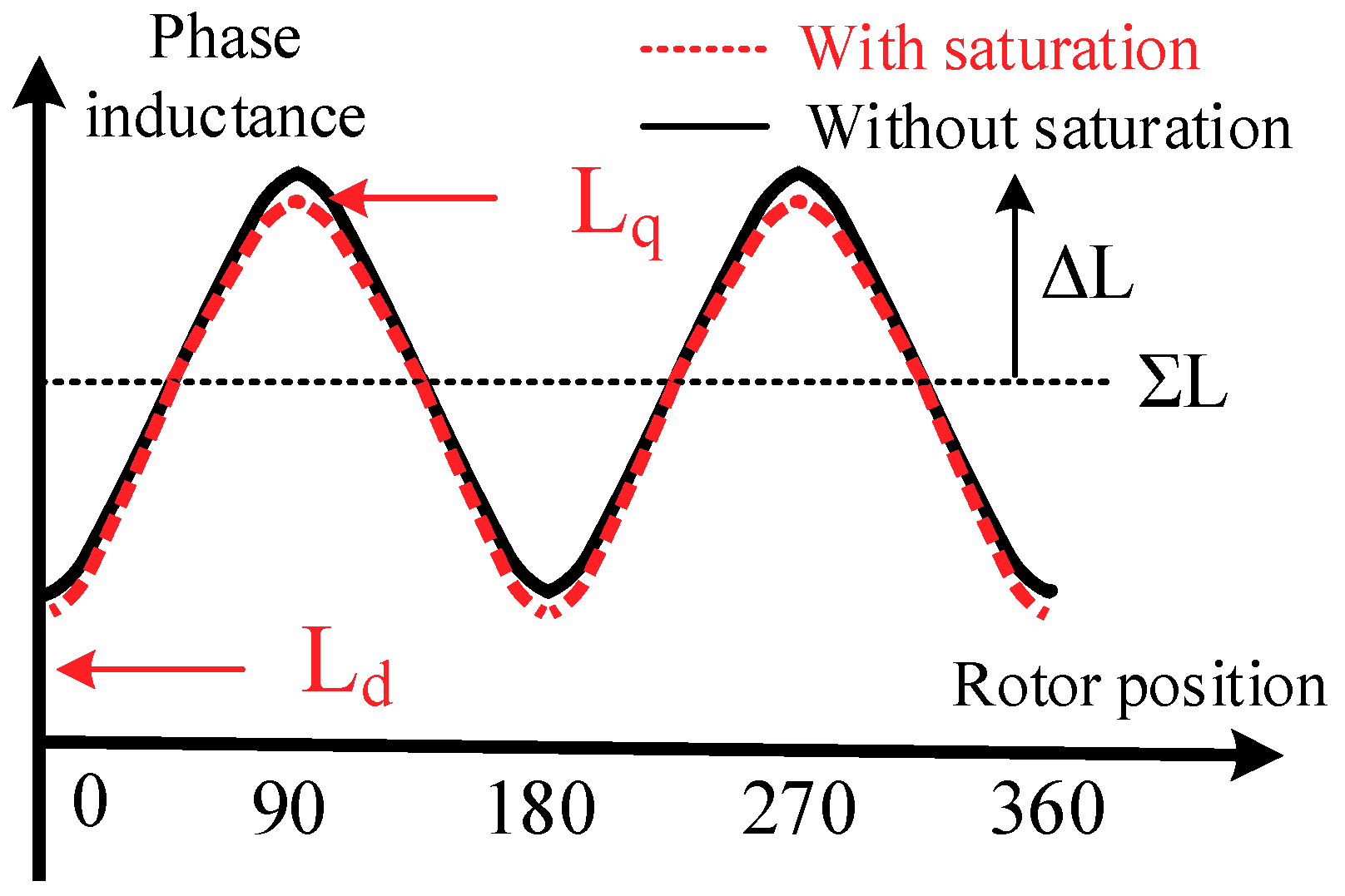
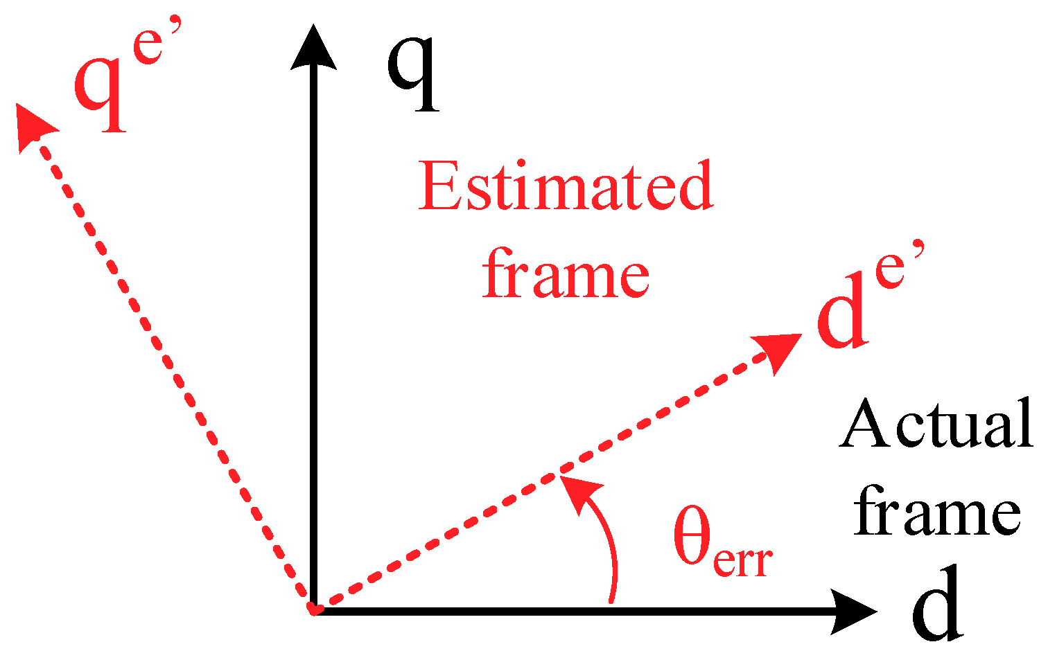
In (2), ΣL and ΔL are the average and differential inductance, respectively. Figure 1 illustrates ΣL and ΔL with respect to the inductance waveform versus position. The superscript e’ in (2) represents the estimated synchronous rotor frame while θerr is the position error between the estimated rotor frame and the actual frame. The relative location between these two rotor frames is shown in Figure 2. The differential operator p in (2) is equal to jωc assuming a steady state with the sine-wave injection. Substituting (1) into (2), the voltage injection induced current is given by
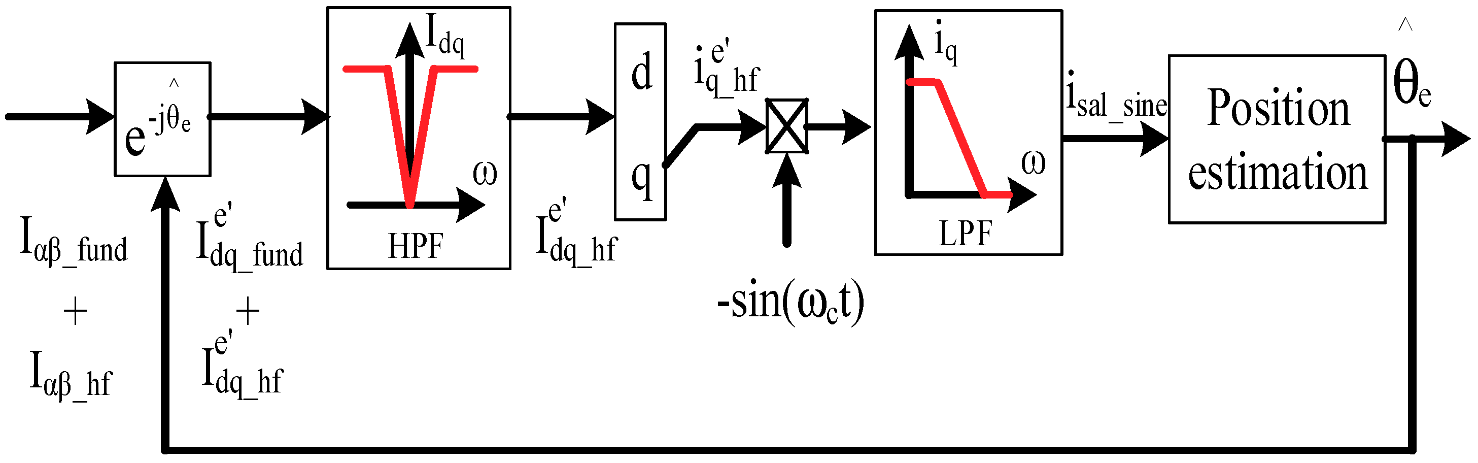
Assuming the estimated frame in Figure 2 is not aligned with the actual frame at the initial estimation state, a saliency current in (3) appears where the magnitude is dependent on ΔL. The rotor position can be obtained by regulating θerr to be zero in . However, is modulated by cos(ωct) due to the HF sine-wave injection. In [19,20], a signal process by multiplying the same per unit sine voltage and adding a low-pass filter (LPF) is proposed to obtain the spatial saliency signal, isal_sine. Figure 3 illustrates the signal process of saliency-based position estimation using a sine-wave voltage injection. In addition to the LPF, a high-pass filter (HPF) is applied to isolate the injection-induced current from the fundamental current. The corresponding analytical equation of isal_sine is given by
In (4), only a single saliency harmonic with respect to 2θe is considered [10]. It is assumed that the phase inductance waveform in Figure 1 is purely sinusoidal where the frequency is 2 times with respect to the rotor position. However, for actual machines, flux saturation must occur due to the nonlinear relationship between flux density and magnetic field strength. Considering the flux saturation, the phase inductance waveform might be changed by the red signal in Figure 1. Under this effect, secondary saliency harmonics instead of a 2θe harmonic occur, leading to saliency-based position estimation error. In this paper, the ideal saliency signal in (4) is extended to consider saturation saliency harmonics as depicted in (5).
where isal_sine_sat is the saliency signal considering saturation harmonics, and ΔL4 and ΔL6 are the magnitudes of fourth-order and sixth-order saturation harmonics. These secondary harmonics are dependent on the condition of flux saturation. In (5), high-order secondary harmonics (larger than sixth-order) are negligible. Due to the influence of saturation harmonics, periodic position estimation errors might occur on the position estimation using the sine-wave voltage injection.
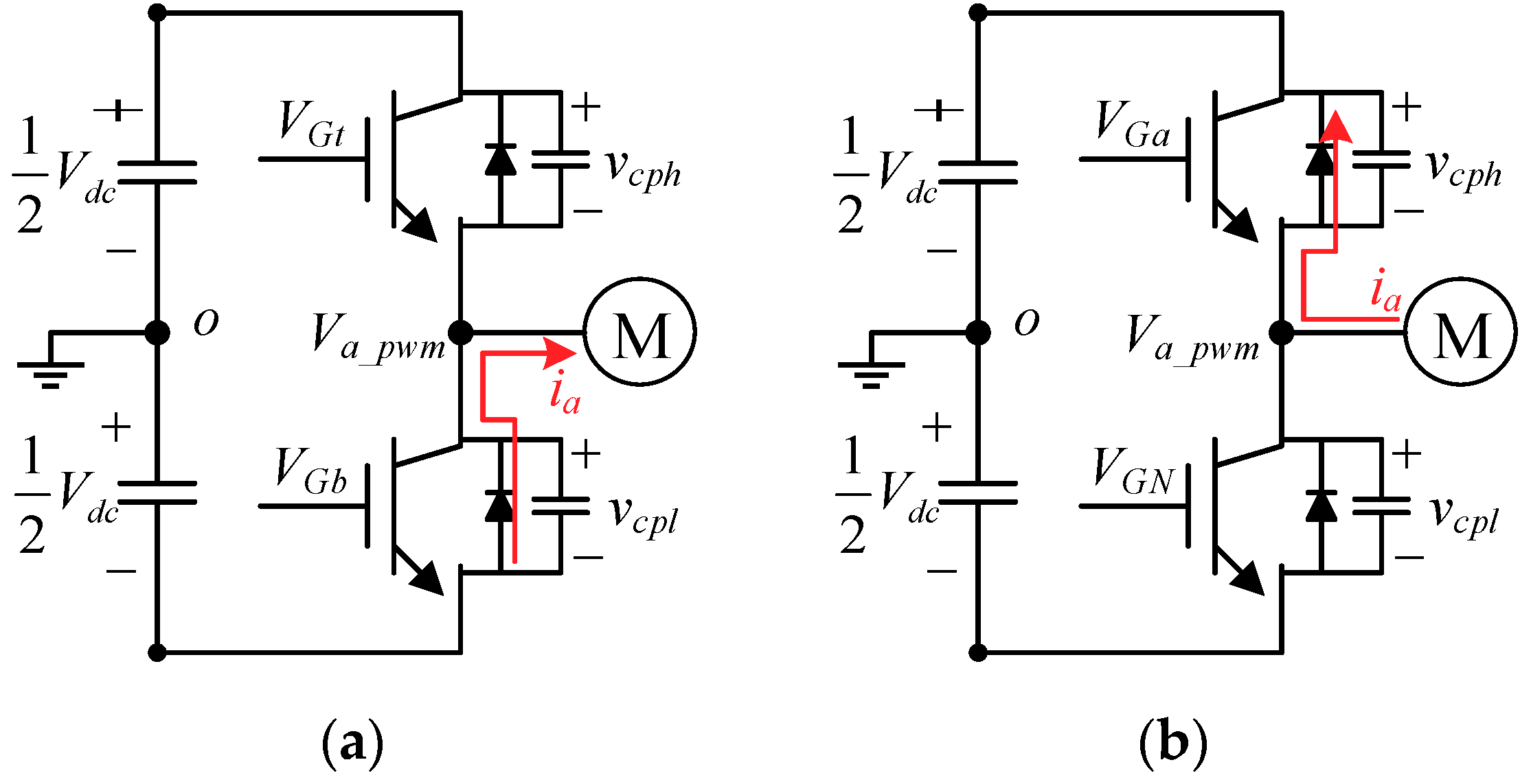
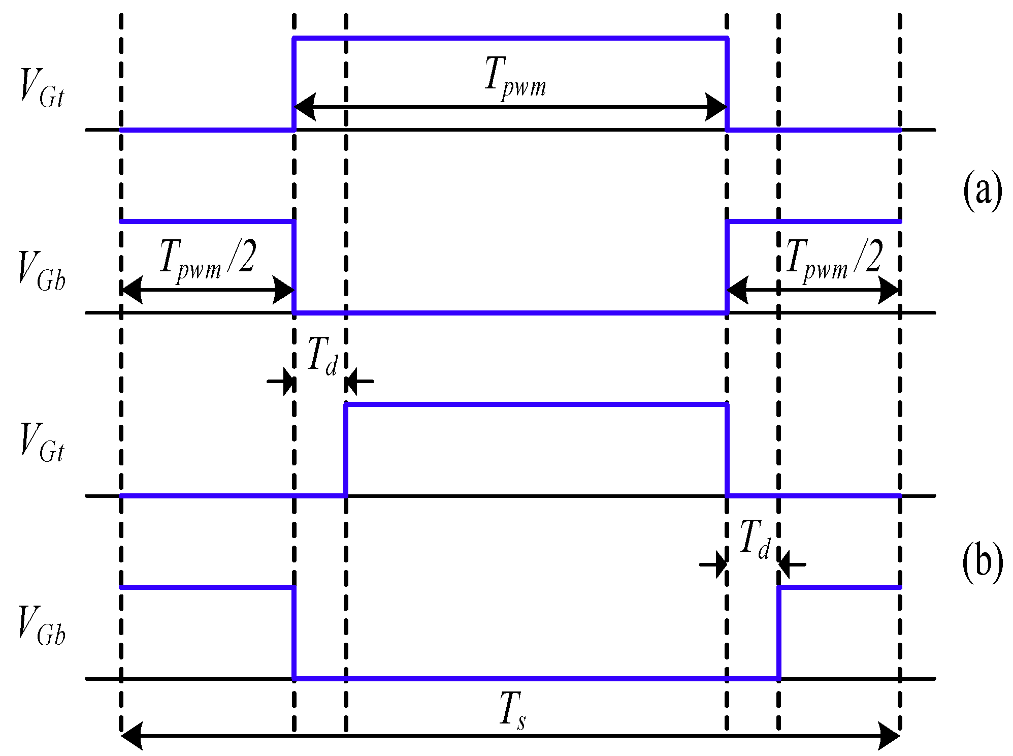
In addition to the flux saturation, inverter dead-time also causes secondary harmonics in the saliency signal isal_sine. Figure 4 illustrates the dead-time effect on the inverter’s A-phase leg. In (a), when both gate signals VGt and VGb suddenly turn off, the phase current flows from the low-side diode Db to the windings when the current polarity is positive. At this instant, a negative voltage error results on the A-phase PWM voltage Va_pwm. By contrast, in (b), once the current is negative, a positive voltage error occurs during the dead-time period. Considering the influence of dead-time, the injection voltage in (1) needs to be corrected by
where Verr_dt_d and Verr_dt_q are the d- and q-axis dead-time voltage error, respectively, which is shown by (7).
In (7), and represent the period of PWM and dead-time, respectively. In addition, and are respectively the switch turn-on and off time period. In this paper, and are assumed to be sufficiently smaller than for simplicity. In addition, sign(i) is the polarity of three phase currents during internal switching, as given by
Figure 5 illustrates the actual A-phase high-side and low-side PWM signal considering the dead-time effect. Substituting (6) into (2), the injection-reflected HF current, and in (3), is
By using the same signal process in (4) with a dead-time effect, the saliency signal is changed by isal_sine_dt in (10).
As shown in (10), dead-time leads to additional harmonics modulated by sin(ωct) in isal_sine_dt. These harmonics are proportional to the dead-time voltage error Verr_dt. However, it is noted that these harmonics can be filtered based on the LPF for the signal process in Figure 3. Thus, the selection of LPF bandwidth is the trade-off between the position estimation bandwidth and the estimation error.
In (10), only the dead-time error is considered. For actual inverter circuits, device parasitic capacities also cause a HF voltage error for the instant when the phase current flows across zero. According to the analysis in [5,6], this error causes a second-order saliency harmonic with respect to the rotor position.
3. HF Square-Wave Voltage Injection
The flux saturation and inverter dead-time on a square-wave voltage saliency-based drive are investigated in this section. As reported in [29,30,31], a square-wave voltage in (11) can be superimposed in the estimated d-axis.
where vsqu is the magnitude of square-wave voltage. By injecting a square-wave voltage, the HF model is given by
In (12), ΔT is the time period of the square-wave voltage. Besides this, and represent the d-axis and q-axis current difference, respectively, based on the current state T1 and the last state T0. They are expressed by
Substituting (11) into (12), and are given by
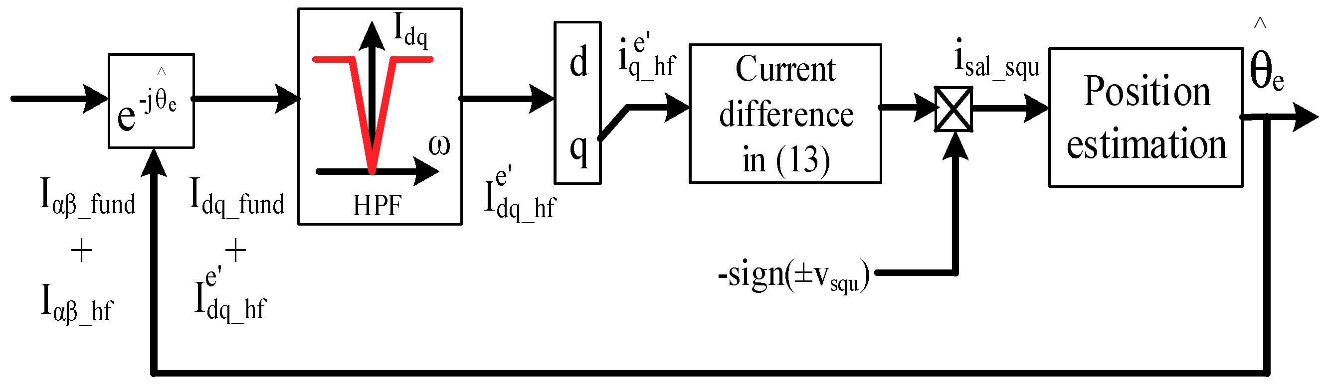
By injecting a square-wave voltage, a position signal dependent on ΔL appears in once the estimated frame in Figure 2 is not the same as the actual frame as shown in Figure 2. Different to sine-wave injection in (4), is modulated by a ± sign due to the square-wave property. A signal process by multiplying the sign was proposed to obtain the saliency signal, isal_squ [30], as seen in (15).
Similar to isal_sine in (4), the rotor position is estimated by regulating θerr in isal_squ to be zero. Figure 6 illustrates the signal processing for the position estimation with square-wave injection. Compared to Figure 3 using sine-wave injection, ± sign correction in (15) instead of an LPF in (4) is applied. By removing the LPF in Figure 6, a higher estimation bandwidth can be of benefit to a sensorless drive.
It is noted that secondary saliency harmonics caused by the flux saturation also occur on the saliency signal with square-wave injection. Considering saturation-reflected saliency harmonics, the saliency signal, isal_squ_scnd, should be modified from (15).
By comparing isal_squ_scnd in (16) and isal_sine_sat in (5), the flux saturation effect is the same on both isal_squ_scnd and isal_sine_sat using either the sine-wave or the square-wave voltage.
The influence of dead-time on the square-wave voltage is also analyzed in this paper. Similar to the sine-wave voltage in (6), the HF square-wave voltage in (11) should be modified by
In (17), the dead-time causes the same voltage error, , mentioned in (7). By replacing (17) into (12), the current differences, and , are shown by
For the position estimation in Figure 6 the saliency signal is obtained based on the demodulation of , which can be derived by
where isal_squ_dt is the saliency current considering the dead-time. By comparing the square-wave saliency signal isal_square_dt in (19) and the sine-wave saliency signal isal_sine_dt in (10), isal_square_dt contains dead-time harmonics where the magnitudes are directly proportional to verr_dt_q. By contrast, isal_sine_dt might achieve negligible dead-time error because of the LPF used in Figure 3. As a result, the position estimation using the sine-wave voltage injection reduces the dead-time error, which can be of benefit to a saliency-based sensorless drive.
4. Experimental Results
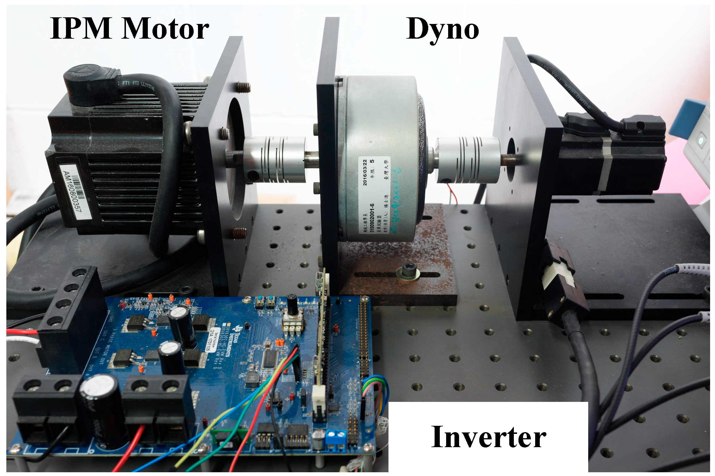
An IPM machine with a 1.41 saliency ratio (Lq/Ld) is built to verify the saliency-based position estimation analyzed in Section 2 and Section 3. Table 1 lists the specifications of this test machine. A two-level inverter with 150-V DC bus voltage is used to generate PWM voltages. The PWM frequency is designed at 10-kHz to balance the dynamic response and switching losses. Figure 7 illustrates the test setup of the saliency-based drive for the test machine. A hysteresis brake is back-to-back connected to the test machine for operation under load. All the control and position-sensing algorithms are implemented in a fixed-point 32-bit microcontroller TI-TMS320F28069. For the following experiments, the magnitudes and frequencies of the two injection voltages are the same at 30 V and 1 kHz to easily evaluate the performance difference.
A. Dead-Time Harmonics:
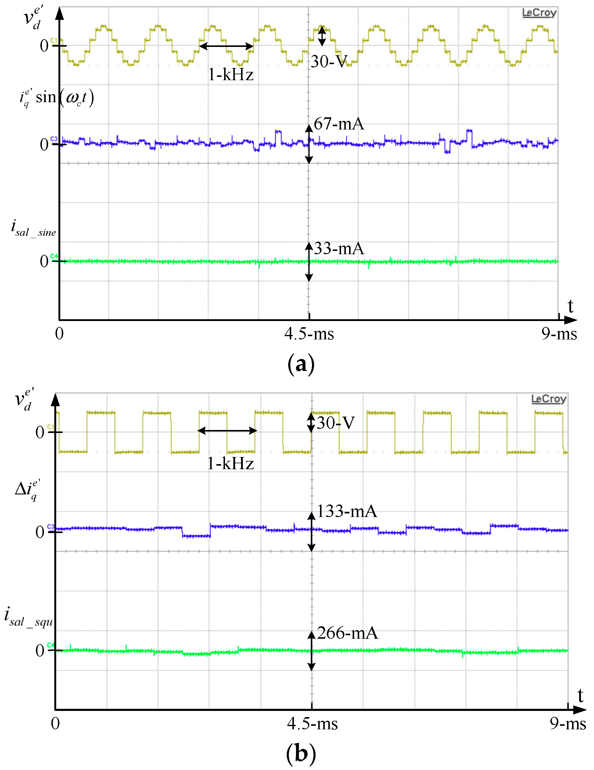
This part evaluates the dead-time effect on both the sine-wave saliency signal, isal_sine_dt, in (9) and the square-wave signal, isal_squ_dt, in (18). The dead-time is set at 2 μs during a 100-μs PWM period.
The rotor position is locked at 0 degrees by applying an external load. Because the rotor is locked, isal_sine_dt and isal_squ_dt should both be maintained at zero considering an ideal inverter without dead-time. Figure 8a illustrates waveforms of in (6) and sin(ωct) and isal_sine_dt in (10). In this figure, sin(ωct) instead of is shown to clearly demonstrate the dead-time distortion on the HF current. By contrast, Figure 8b compares in (16) and and isal_squ_dt in (18). Considering the sine-wave injection signal process in Figure 3, the bandwidths of the LPF and the HPF are respectively designed at 100 Hz and 20 Hz for the experimental tests. In addition, for the square-wave signal process, the HPF in Figure 6 is the same at 20 Hz. It is observed that isal_sine_dt in (a) achieves lower harmonic errors than isal_squ_dt in (b) due to the LPF in Figure 3. This result verifies the analytical model explained in Section 2 It is concluded that the dead-time effect is reduced for the position estimation using the sine-wave voltage injection.
B. Saliency-Based Position Estimation:
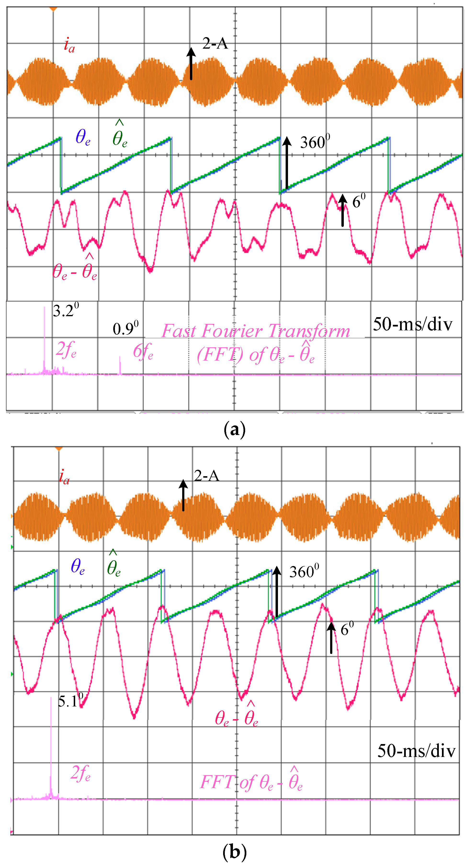
This part compares the saliency-based position estimation using two different voltage injection signals. Both position estimation at no load and full load are evaluated to verify secondary saliency harmonics under different operating conditions. Figure 9 shows the saliency-based position estimation at no load using (a) sine-wave and (b) square-wave voltage injection. The injection frequency is set at 1 kHz to clearly evaluate the position error on the two injection signals. The speed is maintained at 100 rpm (ωe = 2π × 5 rad/s). As seen in (a) using sine-wave voltage, the position error is around 6 degrees consisting of a second- and a sixth-order harmonic. By contrast, in (b) using square-wave voltage injection, the error increases to 8.5 degrees where the second-order harmonic dominates. It is shown that the second-order harmonic using the square-wave injection is higher than that using the sine-wave injection. The dead-time distortion on HF voltages is the primary issue especially when phase currents cross zero.
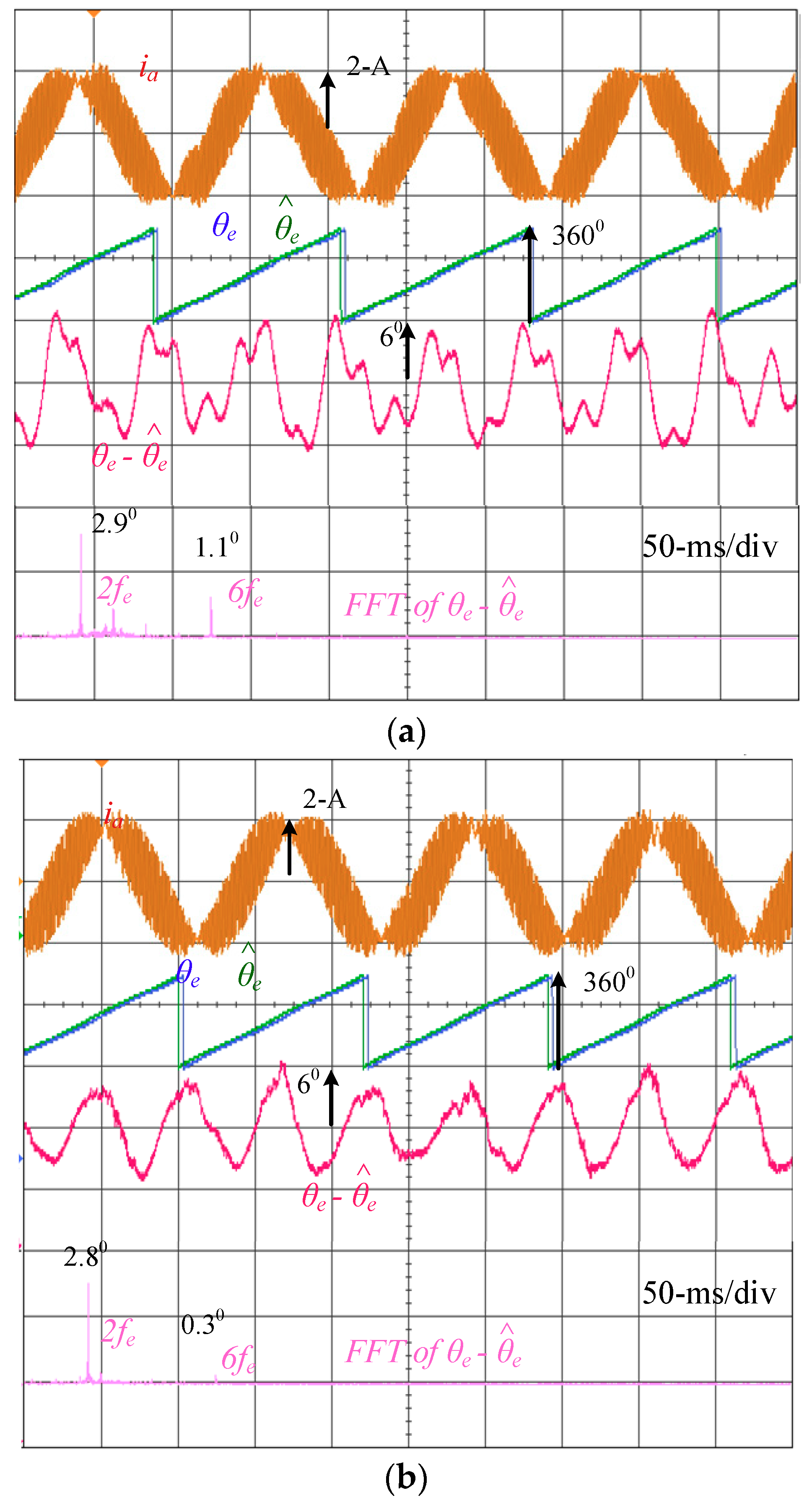
Figure 10 shows the same position estimation comparison at full load. Due to additional fundamental currents for load operation, the dead-time-reflected voltage distortion can be easily compensated for. Under this effect, the position estimation error decreases as the fundamental current increases. For the sine-wave injection in (a), the position error is approximately the same as the error at no load because the dead-time harmonic has been filtered under the demodulation process with an LPF. However, for the square-wave in Figure 10b, the second-order harmonic decreases as the fundamental current increases. This result is consistent with the analysis in Section 4 part B. The dead-time harmonic cannot be filtered for the square-wave injection if the current difference demodulation in Figure 6 is applied. Considering the saliency-based drive using square-wave injection, this visible second-order harmonic at no load can be compensated for if the harmonic magnitude and phase are known based on off-line measurement. In addition, high-voltage magnitude injection is also useful to reduce dead-time harmonics for square-wave injection. By contrast, at full load, the second-order harmonic magnitudes are almost the same between the two different injection signals. This harmonic component is primary caused by the machine’s secondary saliency harmonic which cannot be compensated for by selecting different injection signals.
C. Sensorless Position Control:
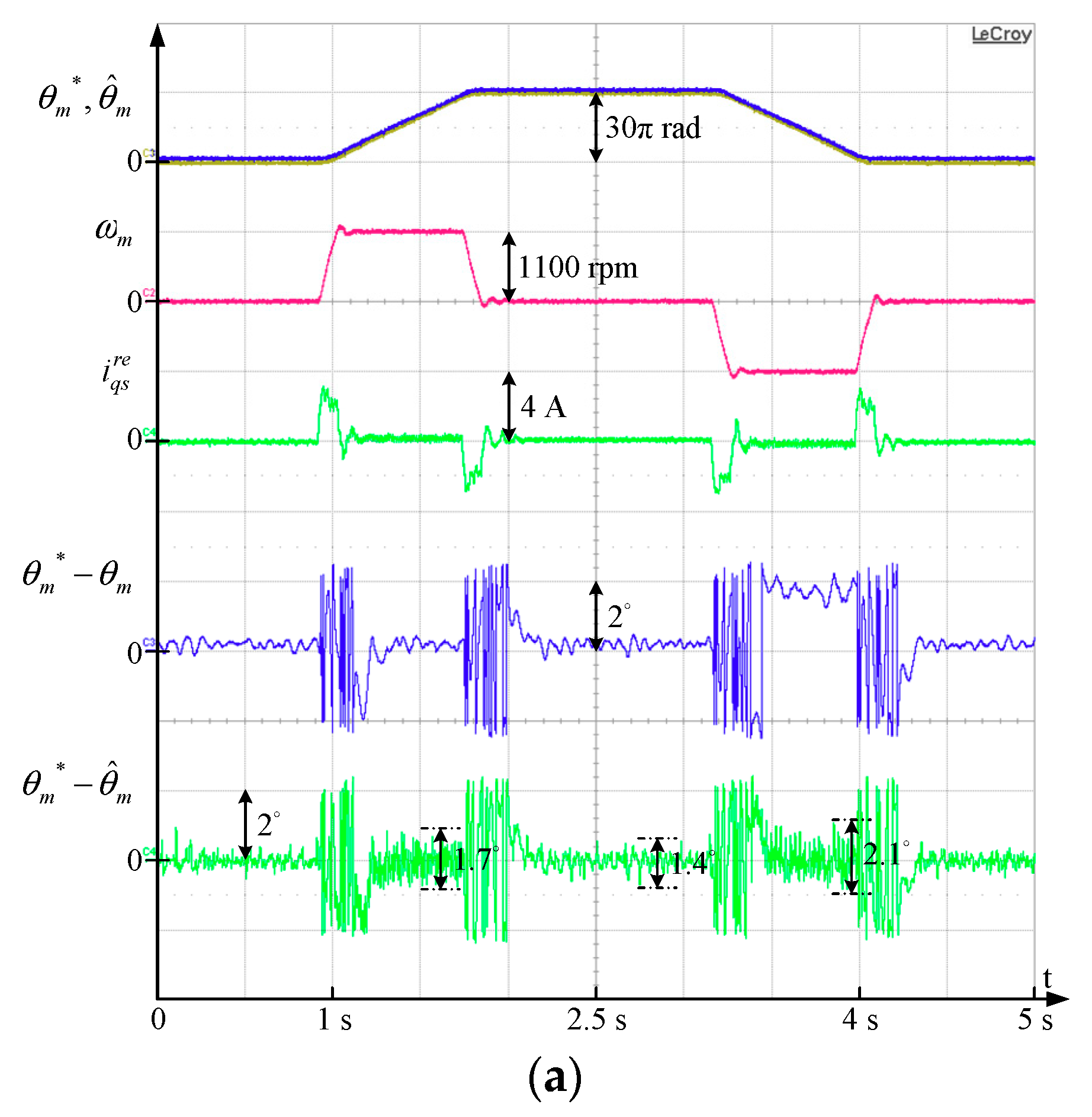
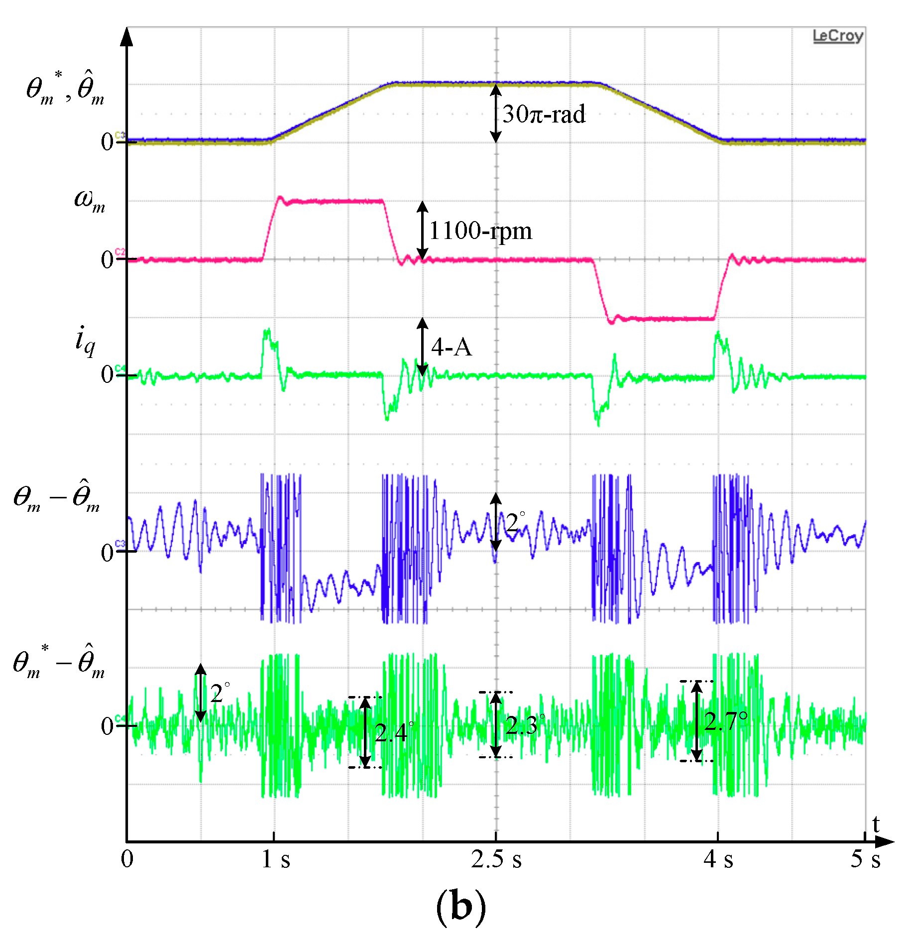
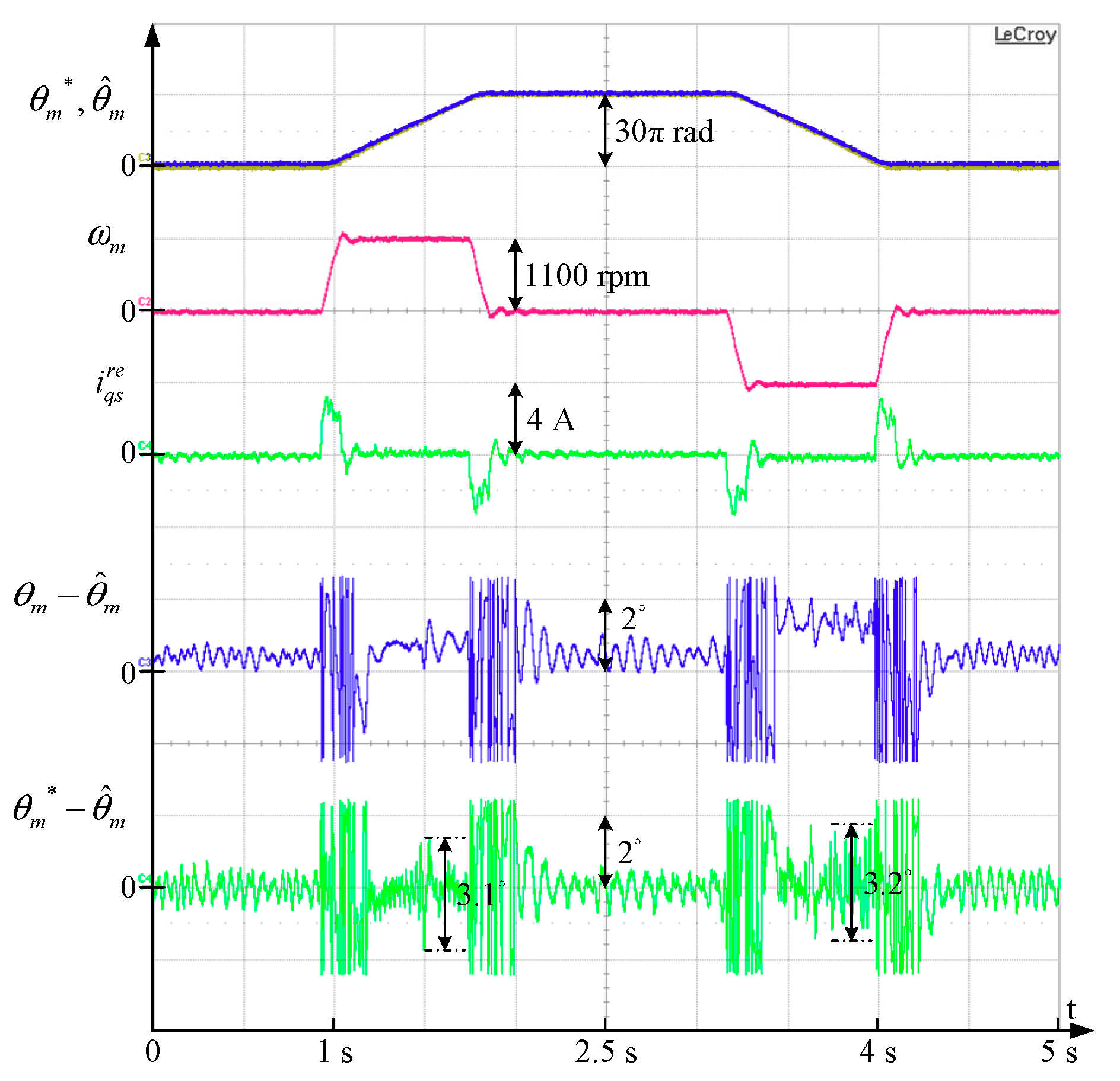
Position control based on saliency-based position estimation using different injection signals is compared in Figure 11. As seen in (a), the saliency-based drive with sine-wave voltage injection is applied. The machine’s position is manipulated from the mechanical position = 0 rad to 30π rad. During the speed transition, the peak-to-peak mechanical position estimation error θm– is around 4.2 degrees. However, this error can be negligible once the drive arrives at steady state. By contrast, the position control error – is around 1.4 degrees at steady state. Figure 11b compares the similar position control with the saliency-based drive while the square-wave voltage is used. At steady state, the estimation error θm– increases to 2 degrees. The control error – also increases to 2.3 degrees, resulting in degraded position control accuracy. Similar to prior experimental results, the influence of dead-time on the square-wave voltage signal is the primary issue to cause this higher estimation error.
It is noted that the injection frequency of both the sine-wave and the square-wave is selected at 1 kHz to compare the position estimation performance. For the sine-wave voltage, the injection frequency is limited by the PWM frequency. High injection frequency might lead to considerable discretized harmonics which is not recommended for position estimation. By contrast, for square-wave voltage, the injection frequency can be increased near the PWM frequency without a discretized effect. Figure 12 shows the same sensorless position control with 5 kHz square-wave voltage injection. In this experiment, the injection flux is maintained the same as in Figure 11b for the comparison of square-wave injection estimation performance using 1 kHz and 5 kHz frequencies. It is observed that the position estimation error decreases as the injection frequency increases. Under the same flux injection, the voltage magnitude is higher for the 5 kHz voltage signal. In general, a high voltage magnitude is useful to reduce the dead-time voltage effect, leading to a reduction of position estimation errors.
5. Conclusions
This paper compares saliency-based position estimation for PM machines using either sine-wave or square-wave injection signals. Key position estimation errors in different saliency signals are analyzed. Experimental results also verify the position estimation errors from the analytical model. The key conclusions are summarized as follows:
- Machine flux saturation causes primary second-order harmonics on the position estimation. This second-order saliency harmonic is the same for an injection using either sine-wave or square-wave voltage.
- Inverter dead-time causes the same error between these two injection voltage signals. However, the position estimation error is reduced for the sine-wave injection because of the LPF used for saliency signal demodulation.
- For the square-wave voltage injection, the dead-time causes a second-order harmonic and a sixth-order harmonic in the position estimation at no load. Since the current difference is used for signal demodulation, these saliency harmonics cannot be removed.
- Although the square-wave injection is sensitive to the dead-time, this voltage signal provides a higher estimation of bandwidth if the injection frequency is increased to the PWM frequency [23,24]. The development of dead-time harmonic compensation is required to further improve saliency-based drives using square-wave injection.
Author Contributions
J.-Y.C. and S.-C.Y. wrote the paper. S.-C.Y. developed saliency-based drive methods. J.-Y.C. implemented and verified all the theories and performed all the experiments. K.-H.T. contributed analysis tools.
Funding
The authors gratefully acknowledge the financial and equipment support from China Engine Corporation and Hua-Chuang Automobile Information Technical Center, Taiwan, China.
Conflicts of Interest
The authors declare no conflict of interest.
References
- Gu, W.; Zhu, X.; Quan, L.; Du, Y. Design and Optimization of Permanent Magnet Brushless Machines for Electric Vehicle Applications. Energies 2015, 8, 13996–14008. [Google Scholar] [CrossRef] [Green Version]
- Hua, W.; Zhou, K.L. Investigation of a Co-Axial Dual-Mechanical Ports Flux-Switching Permanent Magnet Machine for Hybrid Electric Vehicles. Energies 2015, 8, 14361–14379. [Google Scholar] [CrossRef] [Green Version]
- Luo, X.; Niu, S. Maximum Power Point Tracking Sensorless Control of an Axial-Flux Permanent Magnet Vernier Wind Power Generator. Energies 2016, 9, 581. [Google Scholar] [CrossRef]
- Onambele, C.; Elsied, M.; Mpanda Mabwe, A.; El Hajjaji, A. Multi-Phase Modular Drive System: A Case Study in Electrical Aircraft Applications. Energies 2018, 11, 5. [Google Scholar] [CrossRef]
- Pacas, M. Sensorless Drives in Industrial Applications. IEEE Ind. Electron. Mag. 2011, 5, 16–23. [Google Scholar] [CrossRef]
- Murakami, S.; Shiota, T.; Ohto, M.; Ide, K.; Hisatsune, M. Encoderless Servo Drive with Adequately Designed IPMSM for Pulse-Voltage-Injection-Based Position Detection. IEEE Trans. Ind. Appl. 2012, 48, 1922–1930. [Google Scholar] [CrossRef]
- Gamazo-Real, J.C.; Vázquez-Sánchez, E.; Gómez-Gil, J. Position and speed control of brushless dc motors using sensorless techniques and application trends. Sensors 2010, 10, 6901–6947. [Google Scholar] [CrossRef] [PubMed]
- Wang, M.-S.; Tsai, T.-M. Sliding mode and neural network control of sensorless PMSM controlled system for power consumption and performance improvement. Energies 2017, 10, 1780. [Google Scholar] [CrossRef]
- Jansen, P.L.; Lorenz, R.D. Transducerless position and velocity estimation in induction and salient AC machines. IEEE Trans. Ind. Appl. 1995, 31, 240–247. [Google Scholar] [CrossRef] [Green Version]
- Corley, M.J.; Lorenz, R.D. Rotor position and velocity estimation for a salient-pole permanent magnet synchronous machine at standstill and high speeds. IEEE Trans. Ind. Appl. 1998, 34, 784–789. [Google Scholar] [CrossRef] [Green Version]
- Cho, Y. Improved sensorless control of interior permanent magnet sensorless motors using an active damping control strategy. Energies 2016, 9, 135. [Google Scholar] [CrossRef]
- Harnefors, L.; Nee, H.P. A general algorithm for speed and position estimation of AC motors. IEEE Trans. Ind. Electron. 2000, 47, 77–83. [Google Scholar] [CrossRef]
- Pellegrino, G.; Guglielmi, P.; Armando, E.; Bojoi, R.I. Self-Commissioning Algorithm for Inverter Nonlinearity Compensation in Sensorless Induction Motor Drives. IEEE Trans. Ind. Appl. 2010, 46, 1416–1424. [Google Scholar] [CrossRef] [Green Version]
- Raute, R.; Caruana, C.; Staines, C.S.; Cilia, J.; Sumner, M.; Asher, G.M. Analysis and compensation of inverter nonlinearity effect on a sensorless PMSM drive at very low and zero speed operation. IEEE Trans. Ind. Electron. 2010, 57, 4065–4074. [Google Scholar] [CrossRef]
- Antonello, R.; Ortombina, L.; Tinazzi, F.; Zigliotto, M. Enhanced Low-Speed Operations for Sensorless Anisotropic PM Synchronous Motor Drives by a Modified Back-EMF Observer. IEEE Trans. Ind. Electron. 2018, 65, 3069–3076. [Google Scholar] [CrossRef]
- Yang, S.C.; Suzuki, T.; Lorenz, R.D.; Jahns, T.M. Surface-Permanent-Magnet synchronous machine design for saliency-tracking self-sensing position estimation at zero and low speeds. IEEE Trans. Ind. Appl. 2011, 47, 2103–2116. [Google Scholar] [CrossRef]
- Chen, Z.; Gao, J.; Wang, F.; Ma, Z.; Zhang, Z.; Kennel, R. Sensorless control for SPMSM with concentrated windings using multisignal injection method. IEEE Trans. Ind. Electron. 2014, 61, 6624–6634. [Google Scholar] [CrossRef]
- Qiu, X.; Wang, W.; Yang, J.; Jiang, J.; Yang, J. Phase-Inductance-Based position estimation method for interior permanent magnet synchronous motors. Energies 2017, 10, 2002. [Google Scholar] [CrossRef]
- Kim, S.; Sul, S.K. Sensorless control of AC motor—Where are we now? In Proceedings of the 2011 International Conference on Electrical Machines and Systems, Beijing, China, 20–23 August 2011.
- Raca, D.; Garcia, P.; Reigosa, D.D.; Briz, F.; Lorenz, R.D. Carrier-Signal selection for sensorless control of pm synchronous machines at zero and very low speeds. IEEE Trans. Ind. Appl. 2010, 46, 167–178. [Google Scholar] [CrossRef]
- Briz, F.; Degner, M.W. Rotor position estimation. IEEE Ind. Electron. Mag. 2011, 5, 24–36. [Google Scholar] [CrossRef]
- Iwaji, Y.; Takahata, R.; Suzuki, T.; Aoyagi, S. Position sensorless control method at zero-speed region for permanent magnet synchronous motors using the neutral point voltage of stator windings. IEEE Trans. Ind. Appl. 2016, 52, 4020–4028. [Google Scholar] [CrossRef]
- Xu, P.L.; Zhu, Z.Q. Novel. IEEE Trans. Ind. Electron. 2016, 63, 2053–2061. [Google Scholar]
- Park, D.M.; Kim, K.H. Parameter-Independent online compensation scheme for dead time and inverter nonlinearity in IPMSM drive through waveform analysis. IEEE Trans. Ind. Electron. 2014, 61, 701–707. [Google Scholar] [CrossRef]
- Jung, S.; Ha, J.I. Analog filtering method for sensorless ac machine control with carrier-frequency signal injection. IEEE Trans. Ind. Electron. 2015, 62, 5348–5358. [Google Scholar] [CrossRef]
- Kwon, Y.C.; Sul, S.K. Reduction of injection voltage in signal injection sensorless drives using a capacitor-integrated inverter. IEEE Trans. Power Electron. 2017, 32, 6261–6274. [Google Scholar] [CrossRef]
- Wiedmann, K.; Wallrapp, F.; Mertens, A. Analysis of inverter nonlinearity effects on sensorless control for permanent magnet machine drives based on High-Frequency Signal Injection. In Proceedings of the 2009 13th European Conference on Power Electronics and Applications, Barcelona, Spain, 8–10 September 2009. [Google Scholar]
- Kim, D.; Kwon, Y.C.; Sul, S.K.; Kim, J.H.; Yu, R.S. Suppression of injection voltage disturbance for high-frequency square-wave injection sensorless drive with regulation of induced high-frequency current ripple. IEEE Trans. Ind. Appl. 2016, 52, 302–312. [Google Scholar] [CrossRef]
- Hwang, C.E.; Lee, Y.; Sul, S.K. Analysis on the position estimation error in position-sensorless operation using pulsating square wave signal injection. In Proceedings of the 2017 IEEE Energy Conversion Congress and Exposition (ECCE), Cincinnati, OH, USA, 1–5 October 2017. [Google Scholar]
- Lee, Y.; Kwon, Y.C.; Sul, S.K.; Baloch, N.A.; Morimoto, S. Compensation of position estimation error for precise position-sensorless control of IPMSM based on high-frequency pulsating voltage injection. In Proceedings of the 2017 IEEE Energy Conversion Congress and Exposition (ECCE), Cincinnati, OH, USA, 1–5 October 2017. [Google Scholar]
- Reigosa, D.D.; Garcia, P.; Raca, D.; Briz, F.; Lorenz, R.D. Measurement and adaptive decoupling of cross-saturation effects and secondary saliencies in sensorless controlled IPM synchronous machines. IEEE Trans. Ind. Appl. 2008, 44, 1758–1767. [Google Scholar] [CrossRef]
- Garcia, P.; Briz, F.; Raca, D.; Lorenz, R.D. Saliency-Tracking-Based sensorless control of ac machines using structured neural networks. IEEE Trans. Ind. Appl. 2007, 43, 77–86. [Google Scholar] [CrossRef]
- Kim, S.; Ha, J.I.; Sul, S.K. PWM Switching frequency signal injection sensorless method in IPMSM. IEEE Trans. Ind. Appl. 2012, 48, 1576–1587. [Google Scholar] [CrossRef]
- Holtz, J. Acquisition of position error and magnet polarity for sensorless control of PM synchronous machines. IEEE Trans. Ind. Appl. 2008, 44, 1172–1180. [Google Scholar] [CrossRef]
- Yang, S.C.; Yang, S.M.; You, Z.C.; Tsai, Y.Y.; Lee, Y.H. Position estimation capability on saliency-based sensorless drive of permanent magnet machine using different injection signals. In Proceedings of the 2017 IEEE International Electric Machines and Drives Conference (IEMDC), Miami, FL, USA, 21–24 May 2017. [Google Scholar]
Figure 1.
Comparison of phase inductance versus rotor position with and without the flux saturation.
Figure 1.
Comparison of phase inductance versus rotor position with and without the flux saturation.

Figure 2.
Relative location between the estimated rotor frame and the actual rotor frame.

Figure 3.
Illustration of saliency-based position estimation by injecting a sine-wave voltage in the d-axis. HPF, high-pass filter; LPF, low-pass filter.
Figure 3.
Illustration of saliency-based position estimation by injecting a sine-wave voltage in the d-axis. HPF, high-pass filter; LPF, low-pass filter.

Figure 4.
Illustration of A-phase current in the inverter leg during dead-time when the current polarity is (a) positive and (b) negative.
Figure 4.
Illustration of A-phase current in the inverter leg during dead-time when the current polarity is (a) positive and (b) negative.

Figure 5.
Voltage gate signals VGt and VGb in an inverter (a) with and (b) without the dead-time.

Figure 6.
Illustration of saliency-based position estimation by injecting a square-wave voltage in the d-axis.
Figure 6.
Illustration of saliency-based position estimation by injecting a square-wave voltage in the d-axis.

Figure 7.
Test bench of the interior permanent magnet (IPM) machine with the saliency-based sensorless drive.
Figure 7.
Test bench of the interior permanent magnet (IPM) machine with the saliency-based sensorless drive.

Figure 8.
Comparison of saliency signals by injecting (a) the sine-wave voltage signal and (b) the square-wave voltage signal (VC = Vsqu= 30 V, fC = fsqu = 1 kHz and the machine is locked at standstill).
Figure 8.
Comparison of saliency signals by injecting (a) the sine-wave voltage signal and (b) the square-wave voltage signal (VC = Vsqu= 30 V, fC = fsqu = 1 kHz and the machine is locked at standstill).

Figure 9.
Saliency-based position estimation at no load using (a) sine-wave and (b) square-wave voltage injection (VC = Vsqu = 30 V, fC = fsqu = 1 kHz and 100 rpm speed control where ωe = 2π × 5 rad/s).
Figure 9.
Saliency-based position estimation at no load using (a) sine-wave and (b) square-wave voltage injection (VC = Vsqu = 30 V, fC = fsqu = 1 kHz and 100 rpm speed control where ωe = 2π × 5 rad/s).

Figure 10.
Saliency-based position estimation at full load using (a) sine-wave and (b) square-wave voltage injection (VC = Vsqu = 30 V, fC = fsqu = 1 kHz and 100 rpm speed control where ωe = 2π × 5 rad/s).
Figure 10.
Saliency-based position estimation at full load using (a) sine-wave and (b) square-wave voltage injection (VC = Vsqu = 30 V, fC = fsqu = 1 kHz and 100 rpm speed control where ωe = 2π × 5 rad/s).

Figure 11.
Sensorless position control using (a) sine-wave and (b) square-wave voltage injection (VC = Vsqu = 30 V, and fC = fsqu = 1 kHz).
Figure 11.
Sensorless position control using (a) sine-wave and (b) square-wave voltage injection (VC = Vsqu = 30 V, and fC = fsqu = 1 kHz).


Figure 12.
Sensorless position control using square-wave voltage injection (Vsqu = 150 V and fsqu = 5 kHz).
Figure 12.
Sensorless position control using square-wave voltage injection (Vsqu = 150 V and fsqu = 5 kHz).


Table 1.
Test Machine Characteristics.
| Characteristics | Values |
|---|---|
| Rotor poles | 6 poles |
| Rated torque | 0.58 Nm |
| Rated current | 2 A |
| Rated speed | 6000 rpm |
| Resistance | 1.15 Ω |
| Inductance | 4.6 mH(Ld)/6.5 mH(Lq) |
| DC bus voltage | 310 V |
© 2018 by the authors. Licensee MDPI, Basel, Switzerland. This article is an open access article distributed under the terms and conditions of the Creative Commons Attribution (CC BY) license (http://creativecommons.org/licenses/by/4.0/).
Share and Cite
MDPI and ACS Style
Chen, J.-Y.; Yang, S.-C.; Tu, K.-H. Comparative Evaluation of a Permanent Magnet Machine Saliency-Based Drive with Sine-Wave and Square-Wave Voltage Injection. Energies 2018, 11, 2189. https://doi.org/10.3390/en11092189
AMA Style
Chen J-Y, Yang S-C, Tu K-H. Comparative Evaluation of a Permanent Magnet Machine Saliency-Based Drive with Sine-Wave and Square-Wave Voltage Injection. Energies. 2018; 11(9):2189. https://doi.org/10.3390/en11092189
Chicago/Turabian StyleChen, Jyun-You, Shih-Chin Yang, and Kai-Hsiang Tu. 2018. "Comparative Evaluation of a Permanent Magnet Machine Saliency-Based Drive with Sine-Wave and Square-Wave Voltage Injection" Energies 11, no. 9: 2189. https://doi.org/10.3390/en11092189
Note that from the first issue of 2016, this journal uses article numbers instead of page numbers. See further details here.