Dynamic Optimization of Combined Cooling, Heating, and Power Systems with Energy Storage Units


School of Control Science and Engineering, Shandong University, Jinan 250061, China
*
Author to whom correspondence should be addressed.
Energies 2018, 11(9), 2288; https://doi.org/10.3390/en11092288
Submission received: 4 August 2018
/
Revised: 28 August 2018
/
Accepted: 29 August 2018
/
Published: 30 August 2018
(This article belongs to the Special Issue Optimization Methods Applied to Power Systems)
Abstract
:In this paper, a combined cooling, heating, and power (CCHP) system with thermal storage tanks is introduced. Considering the plants’ off-design performance, an efficient methodology is introduced to determine the most economical operation schedule. The complex CCHP system’s state transition equation is extracted by selecting the stored cooling and heating energy as the discretized state variables. Referring to the concept of variable cost and constant cost, repeated computations are saved in phase operating cost calculations. Therefore, the most economical operation schedule is obtained by employing a dynamic solving framework in an extremely short time. The simulation results indicated that the optimized operating cost is reduced by 40.8% compared to the traditional energy supply system.
1. Introduction
Combined cooling, heating, and power (CCHP) systems follow the principle of cascade utilization of energy with high energy efficiency and have become a major research focus [1,2,3,4,5,6]. It is verified that operation optimization can improve their performance to some extent [7,8,9,10]. However, fluctuating energy demands might not always fall within the high efficiency region of CCHP systems [11,12]. Satisfactory operation cannot be achieved easily without energy storage units, which can facilitate high-efficiency CCHP system operation and increase the energy conservation rate by approximately 21% [13]. Meanwhile, the introduction of energy storage units makes CCHP system optimization very difficult [14,15].
The most common operating strategy is based on following the electric loads or following the thermal loads [16,17]. Current studies solve the optimal operating strategy of CCHP systems with storage units in the following way: the outputs of different pieces of equipment in each stage are taken as equivalent optimization variables, which are limited by the plant capacity and energy balance. After setting an objective function, various kinds of algorithms are applied with the objective of seeking the optimal operating schedule. The current studies can be separated into the following two general categories based on their algorithms.
Nearly half of the published research papers employ intelligent optimization algorithms, which are mainly genetic algorithms (GAs) and particle swarm optimization (PSO) algorithms, to solve the CCHP system operation optimization problem. Wang et al. employed GA to optimize an electric load-following operating strategy of a CCHP system [18]. Zeng et al. employed GA to determine the optimal operating solution of a CCHP system combined with ground source heat pumps [19]. Wang et al. built a two-time scale optimized model of a CCHP system, and an improved PSO algorithm is proposed [20]. Considering the co-optimization issue of CCHP system with ice-storage air-conditioners, Bao et al. introduced the Improved PSO algorithm to the solution of the day-ahead operating schedule [21].
Numerous examples of linear programming (LP) applications to CCHP system operation optimization can also be found. Shaneb et al. purposed an optimal online operation of residential CCHP systems using LP [22]. Bischia et al. built a detailed nonlinear CCHP system model, which was piecewise approximated as several linear models, and introduced mixed-integer linear programming (MILP) to optimize the operating schedule [23]. Gu et al. built a prediction control model of a CCHP system; its prediction errors and system deviations were corrected online by rolling optimization, and the dispatch schedule in each step of the rolling optimization was determined by using MILP [24]. Luo et al. proposed two-stage optimization and control structure of the CCHP system, and employed MILP to search the operating schedule [25].
GA, PSO, and MILP can easily optimize the CCHP system operation as long as storage units are not introduced. However, the operation optimization of CCHP systems with storage units is more complex than that of systems without storage units [26], and the methods mentioned above cannot handle the optimization of such systems adequately. Difficulties arise not only from the numerous optimization variables corresponding to each stage, but also because of the correlation between adjacent stages due to the existence of storage units [27]. To be more specific, the energy storage state of each stage depends on the energy supply of the previous stage, whereas the energy supply of each stage is influenced by its current energy storage. To describe the correlation between the adjacent stages, complex constraints must be applied.
Hence, it is not certain that GA or PSO can provide optimal solutions. This conclusion is derived from the fact that different results are obtained for the same problem when they are applied repeatedly. MILP is improved to be efficient when the optimization model is considered to be linear. However, to the best of our knowledge, there is no linear CCHP system that has already been developed, so the piecewise linearity model is constantly used when considering off-design performance. As a result, the computation load is large.
Very few studies have employed dynamic programming in CCHP system operating optimization. Facci et al. applied dynamic programming to a no-storage CCHP system. Considering that generator restart would require extra cost, the generator status in terms of starting and stopping was set as a 0–1 state variable and dynamic programming was employed [28]. Based on previous work, Facci et al. built a CCHP system with storage units. Considering the off-design performance, a dynamic model was established. To reduce the difficulties of the non-linear optimizing problem, dynamic programming combined with meta-heuristic optimization is applied [29].
Their study represented a rare example of the application of dynamic programming to CCHP system operation optimization. However, existing studies maintain a relatively simple system structure. The computation will increase significantly as more plants are introduced, particularly storage units. Further research on dynamic programming applications should be conducted for CCHP systems with complex structure.
In summary, the operation optimization of CCHP systems with storage units should be solved dynamically. Traditional methods such as PSO, GA, and MILP cannot be utilized to tackle it successfully. By resolving the dynamic problem in stages, a dynamic solving framework is created. The computation reduction in complex systems needs significant research, though the prospect of dynamic programming has been confirmed preliminarily.
In this paper, a common CCHP system is proposed. The electric demand is supplied by a power generation unit (PGU) and the power grid. The excess electricity can be sold back to grid. The recovered thermal energy is used to satisfy heating and cooling demands. In addition, two separate heat pumps can also be used to satisfy the thermal demands. The difference between thermal the energy demand and supply can be offset using the thermal storage tanks. The state transition equation is extracted according to the dynamic relationship of the energy storage. A dynamic optimization is proposed to determine the most economical operating schedule. The CCHP system operating optimization is divided into small static problems based on the framework of dynamic programming. The economical concept of variable cost and constant cost are introduced to solve static problems, which can be expressed by the same mathematical model and then solved by the same method with very few computations. As the day-ahead optimization simulation shows, significant improvements over the traditional energy system have been achieved.
2. CCHP System Modeling
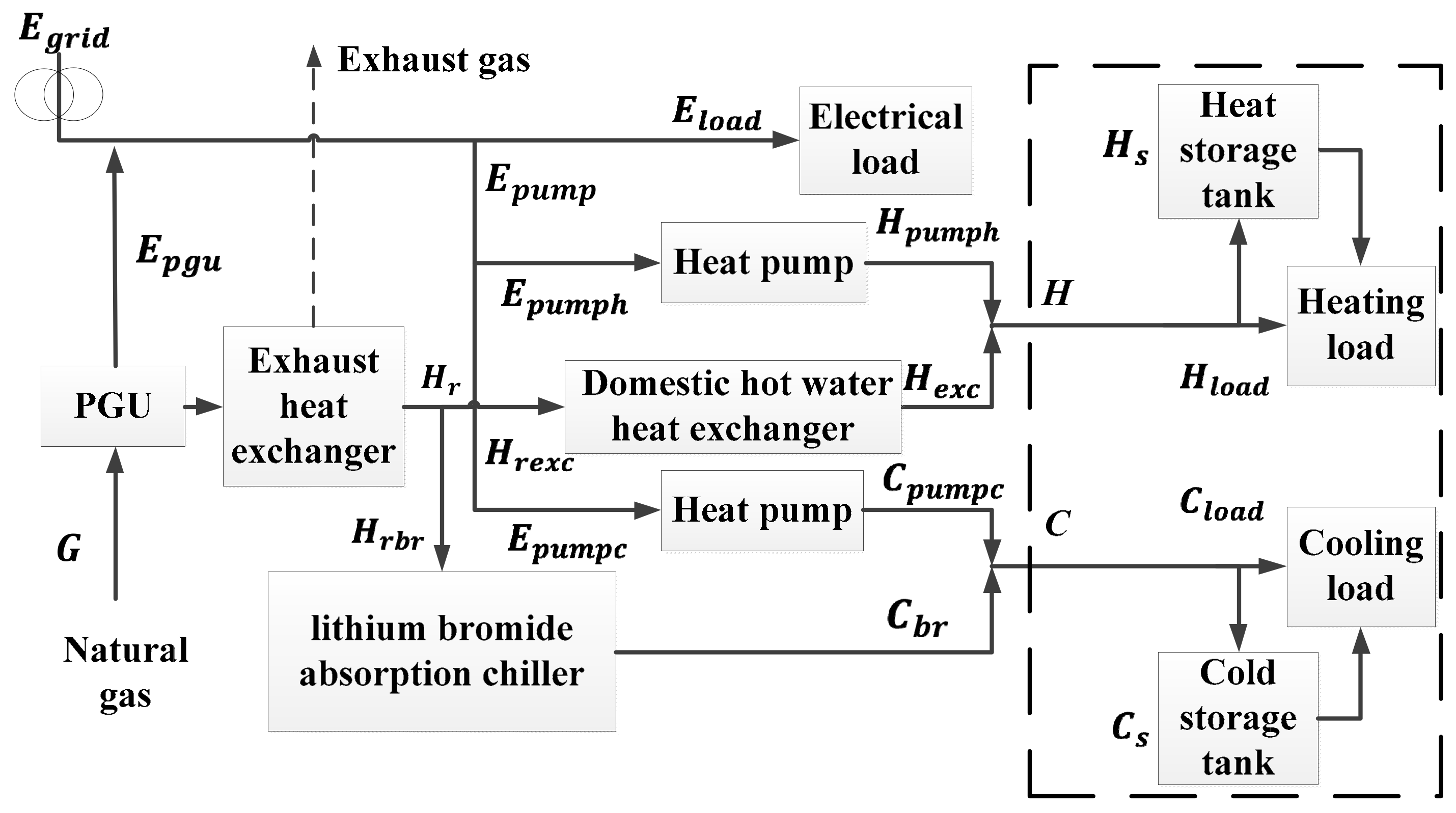
The structure and energy flux of the CCHP system are depicted in Figure 1. The power generation unit (PGU), which is connected to the grid, consumes natural gas to generate electricity and thermal energy simultaneously. The exhaust heat exchanger transfers heat from the exhaust gas to jacket water. The absorption chiller recovers energy from the jacket water to produce cooling water. Similarly, the domestic hot water heat exchanger recovers energy from the jacket water to produce domestic hot water. The chiller and exchanger are assisted by separate heat pumps. The thermal storage tanks store extra energy and supply it when necessary. In winter, the cooling demand changes to a space heating demand and the original cold storage tank is employed to store heating water. Meanwhile, the absorption chiller functions as a normal heat exchanger to satisfy the heating demand associated with the corresponding heat pump. It must be noted that each of the operations of the equipment obeys the solution for operating optimization.
2.1. State Transition Equation of CCHP System
The components enclosed within a rectangle with dashed borders in Figure 1 constitute the critical section of this system. The state transition equation of the dynamic relationships of the production, load, and stored energy between the th hour and th hour can be expressed as follows:
where is the heat storage efficiency, which represents the proportion of thermal energy remaining after one dissipation stage, and has a similar physical significance; and represent the quantities of stored heating and cooling energy, respectively. The heating and cooling contribution of heat pump are signified as and , respectively. and are the chiller and exchanger outputs, respectively. and are heating and cooling energy demands, respectively. is the total operating cost and is the phase cost.
Equation (1) is the core of this paper, based on which the dynamic solving framework is established. Therefore, the huge dynamic problem of CCHP system operating optimization is dynamically broken up into smaller static problems. The operating cost function is the key of static problem, which will be discussed in chapter three.
2.2. Plant Modeling
The PGU is a gas-fired small internal combustion generating set, whose data is listed in Table 1.
Taking and as the exhaust heat exchanger efficiency and the dissipated thermal energy ratio of jacket water in heat exchanging process, respectively, the waste heat recovery ratio is given by:
The recovered waste heat is used to drive the absorption chiller and domestic hot water heat exchanger, whose efficiency are and , respectively. The contribution of the absorption chiller and heat exchanger are and , respectively. The chilling and heating coefficient of performance (COP) of the electric heat pump are and , respectively. The heating and cooling contribution of heat pump are and , respectively. The consumed electricity of heat pump is .
3. Methodology
3.1. Optimal Operation Model
The optimization of a CCHP system with storage units is dynamic in nature. Thus, the solution framework is based on dynamic programing. The state variable selection is the most important step in dynamic programing. Energy storage should be chosen because it serves as a link between adjacent stages (see Equations (1)). Thereupon, the optimization model can be established. The state variable discretization is as follows.
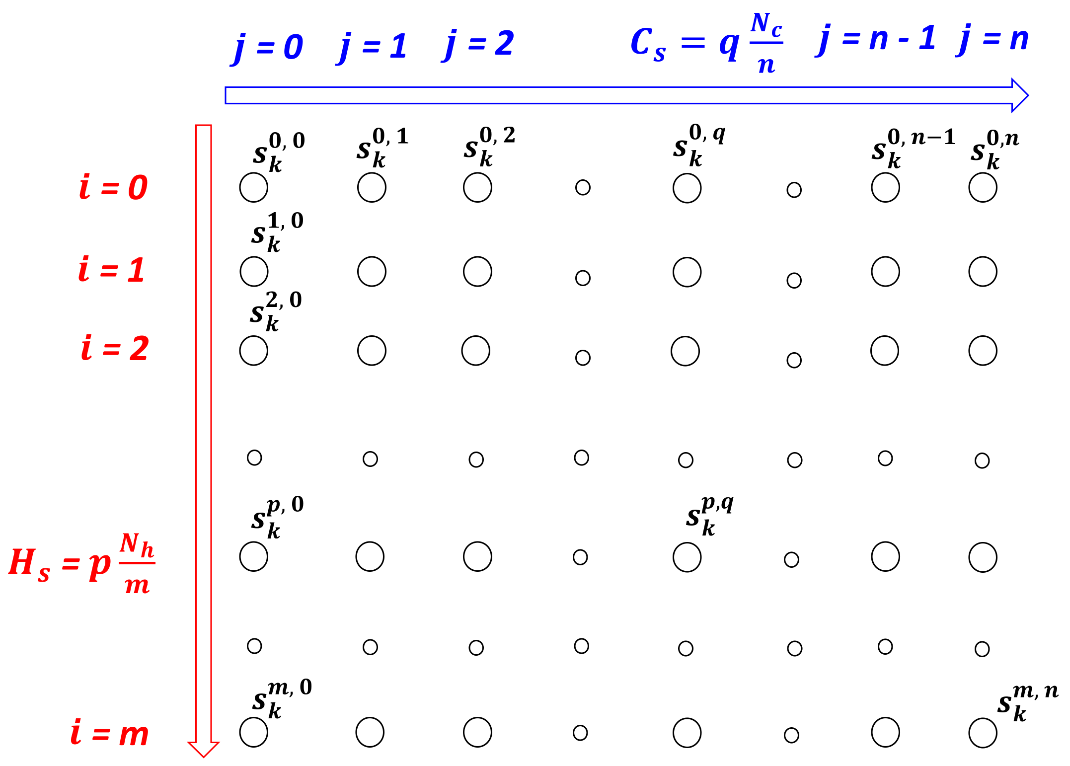
denotes the heating and cooling energy storage of stage k, where and . and are the capacities of the heating and cooling storage tanks, respectively. After setting m and n, can be discretized into state points. The state point can be expressed simply as , where , and . The set of is expressed as . Larger m and n lead to more accurate discretization and more state points.
According to the discretization described above, is arrayed as depicted in Figure 2.
represents the optimal operation solution of the CCHP system for transferring to . The corresponding cost is expressed as . The method to solve and is proposed in Section 3.3.
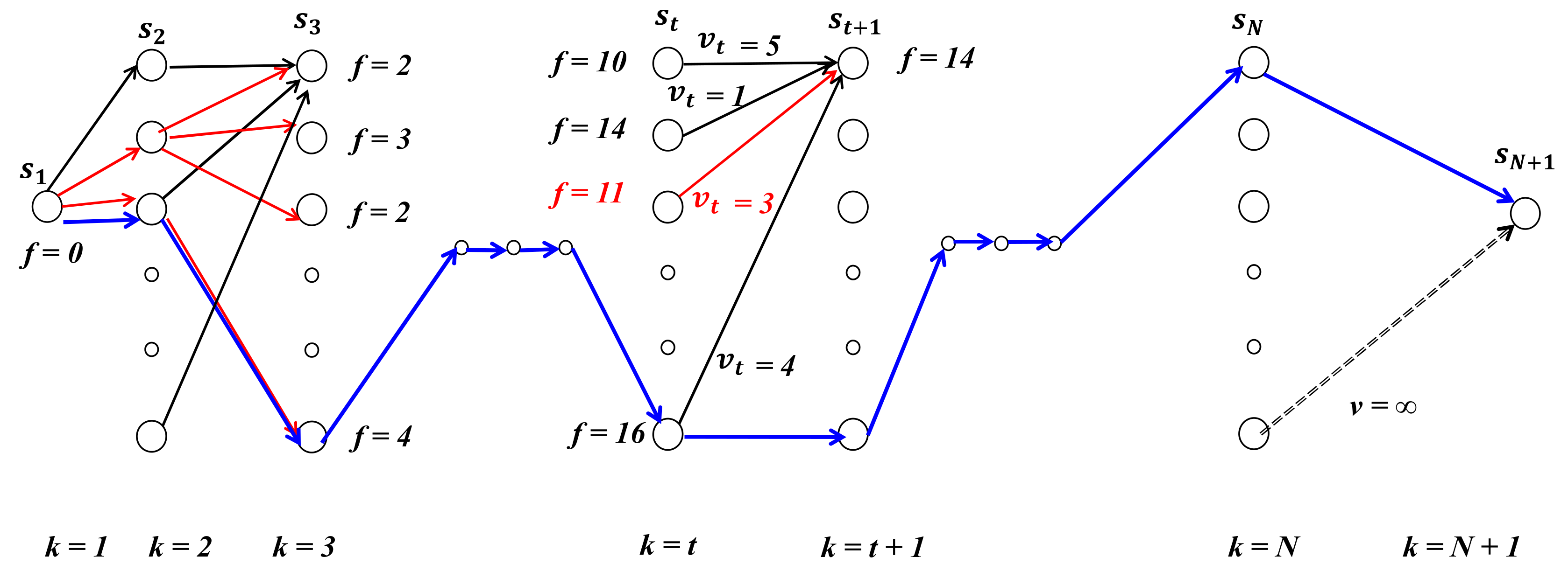
The shortest path model of the CCHP system operation optimization problem is as shown in Figure 3. The energy storage in each stage corresponds to a point set . Based on the state point selected in the previous stage, the path from to has a unique length expressed as . The minimum cost of the CCHP system operating schedule is represented by the length of the shortest path from to .
The shortest path problem of CCHP system operation can be described as follows. The oriented graph in Figure 3 is represented as , and (the state points of adjacent stages) are joined by an oriented arc , and the weight of the arc is represented as , where . If there is no arc joining and , then is set to . Suppose is a path of from the initial point to the end point , and define the weight of as the sum of each arc in , represented as . The objective of this shortest path problem is to find the minimum-weight path among all of the paths from to , where:
is the shortest path from to . The weight of is the distance from to , represented as . For CCHP system operation, is the minimum operating cost. Thus, the optimization problem can be solved by finding .
3.2. Shortest Path Determination Based on Dynamic Programming
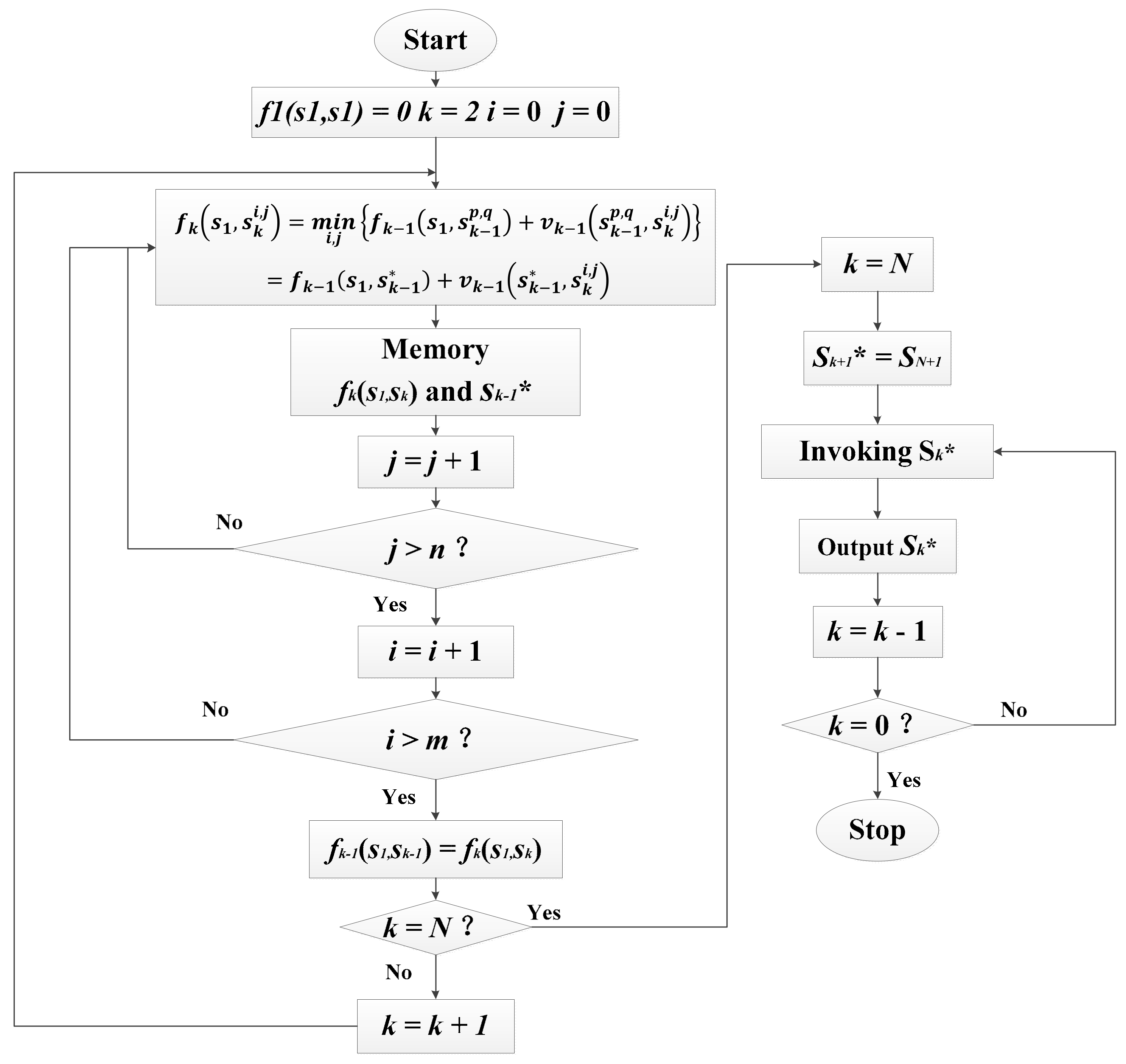
The shortest path search is a multi-stage decision problem. The optimality principle was developed particularly to solve this kind of issue. Moreover, dynamic programming is proposed by transforming the multi-stage process into single stages. The result obtained by dynamic programming is certain to be optimal due to optimality principle. The best methods recognized for solving the shortest path problem involve dynamic programming without exception. The diagram of the dynamic programming flow used in this paper is provided in Figure 4.
The shortest path from to always starts from , passing through one state point , and finally arriving at . According to the optimality principle, the path from to is the shortest. Hence, the dynamic programming equation of this model is obtained as:
Using to signify the optimal state point selected from , a more general expressions can be derived as:
and:
As shown in Equations (6) and (7), forward dynamic programming is applied. This problem is solved step by step. Meanwhile, the shortest distance and path selection are recorded. The optimization problem is solved when is obtained.
In addition, as can be seen in Figure 2, larger m and n lead to larger . To reduce the amount of unnecessary calculations, the discretization is separated into two steps. Firstly, the energy storage is discretized with rough accuracy and dynamic programming is applied to search the shortest path. Secondly, the energy storage is discretized with precise accuracy near the path obtained in the first optimization. The second optimizing result is precise to 1 .
3.3. Static Problem: Analysis of Stage Cost
The static problem is searching for the minimum cost resulting from the state transition. In other words, its objective is to determine according to state points and .
According to Equation (1), the heating and cooling production of stage k can be represented by the energy storage of stages k and k + 1. Based on the required energy production, the most economical dispatch strategy and its corresponding cost can be determined by referring to the operation optimization of a no-storage CCHP system, which is a static problem. Although LP, GA, and PSO can be employed, it is time consuming to calculate the static problems repeatedly in dynamic programming. In this section, the operating cost is solved without any optimizations by introducing the concept of variable cost.
The operating cost of a CCHP system consists of electricity and gas costs. The stage cost can be calculated as follows:
where is the consumed natural gas and is the gas price. The amount of electricity received from the power grid is given by:
For the given state points and , the total heating and cooling demand, and , respectively, are fixed.
Based on the modeling of the PGU and exhaust heat exchanger given in Section 2.2, and can be fitted as polynomial functions of . The required data are listed in Table 1 and Table 2. Because is the function of and , the conclusion can be drawn that both and are functions of and . Hence, can be represented as a function of and . Referring to the economics, the operating cost consists of constant cost and variable cost :
Assume that all of the heating and cooling energy is provided by the heat pump and that the electrical load is supplied by the power grid. The constant cost is determined by , , and . In other words, cannot be optimized:
Starting the generator results in an extra gas cost, while the produced power offsets the power bought from the grid. The variable cost represents the change in cost resulting from generator operation at different power levels:
The domain of this function is:
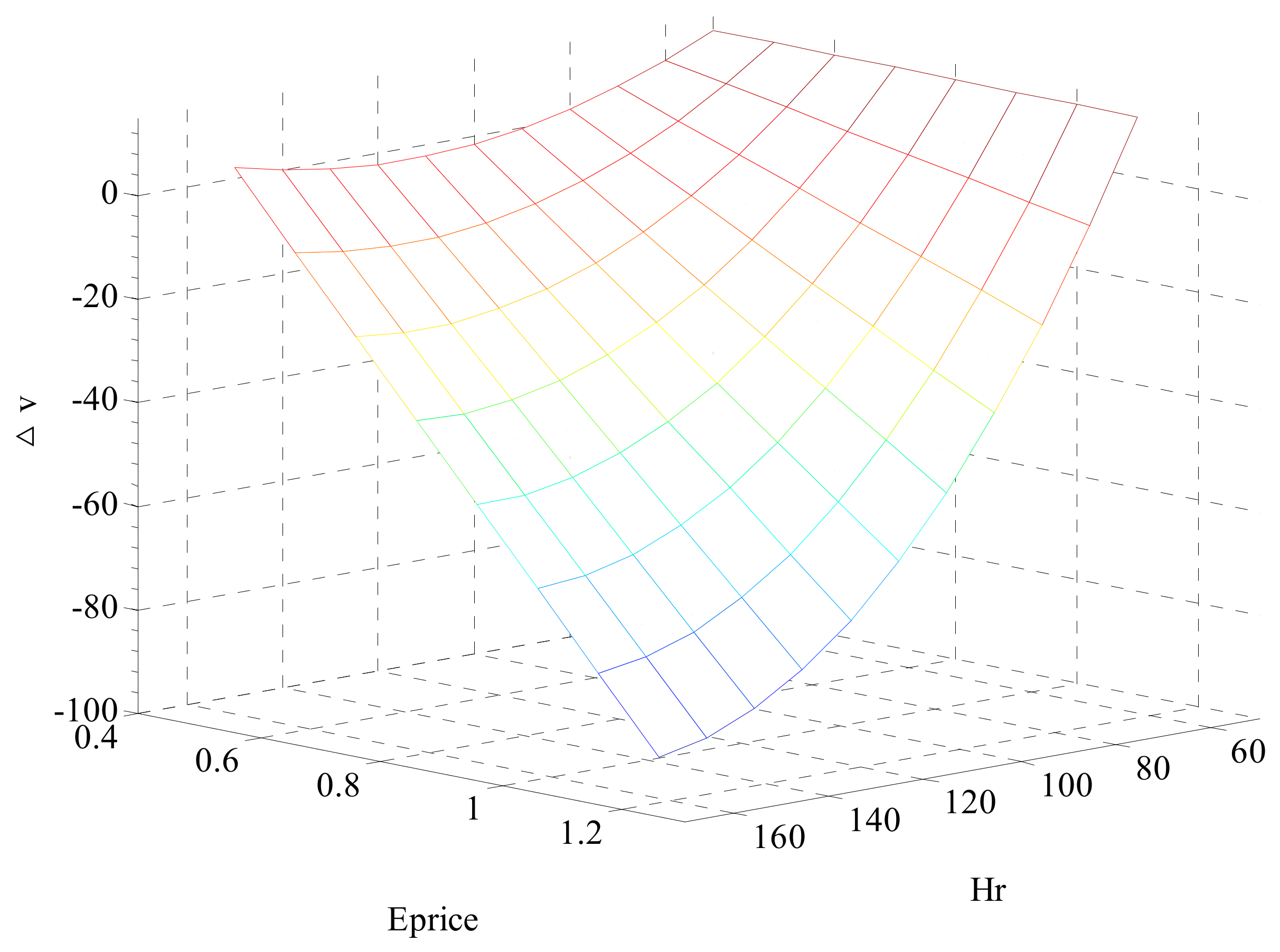
has no relationship with and . To determine the minimum stage operating cost , attention should be paid to , which is a function of and . Hence, the essence of static problems is searching for the minimum value of . According to the expression for , is the most influential parameter. Its influence is shown in Figure 5. For clarity, and are combined into .
According to the expression for , is the most influential parameter. Its influence is shown in Figure 5. For clarity, and are combined into .
When is 1.1 ¥/, all of the heating and cooling is supplied by the absorption chiller and domestic hot water exchanger. When is 0.7 ¥/), the heat recovery of 144.7 corresponds the most economic operating strategy. When is 0.4 ¥/), the heat recovery of 123 corresponds to the peak efficiency of the generator. The generator should work to ensure that the as small as possible, so long as is negative. Otherwise, it is more economical to stop the generator when the efficiency is low.
, , and can be determined based on and . Hence, the optimal dispatch strategy can be described as ,,,. The operating cost is also obtained. By referring to the concept of constant cost and variable cost, thousands of repeated computations can be eliminated.
4. Case Study
4.1. Load Description and Basic Data
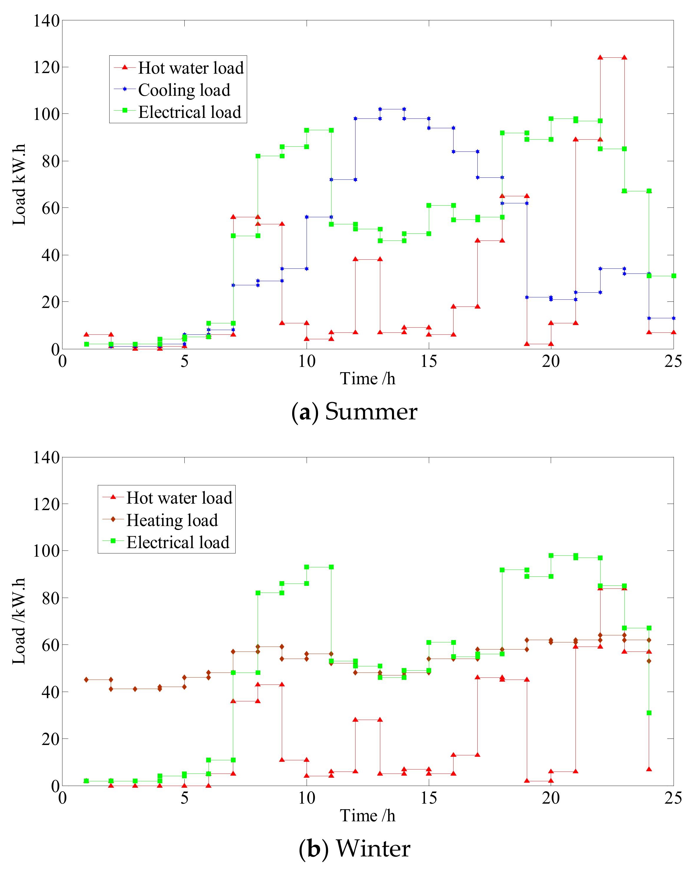
The energy demands can be obtained from [29,32]. The building was simulated using EnergyPlus (5.0.0.035). The description of the simulated building is given in Table 3. For our test case, we selected two typical days in summer and winter, as reported in Figure 6.
In addition, there is no cooling load in winter. Instead, extra hot water is required by the central air-conditioning system to keep the dormitory warm. This part of the hot water is separated from that consumed by bathing and so on. The cooling storage tank is employed to store this part of the hot water.
The electricity price (in Yuan ¥) per hour refers to [33]:
The CCHP system parameters are listed in Table 4.
The parameters of a traditional energy system are listed in Table 5. The heating load is supplied by a gas boiler, the electrical load is supplied by the power grid, and the cooling load is supplied by an electrically driven air conditioning system.
The fuel parameters employed for the traditional energy system and CCHP systems to calculate the operation targets are listed in Table 6.
4.2. Results and Analysis
The state variable discretization process was divided into two steps with accuracy at 10 and 1 . According to the discretization method described in Section 3.1, the amount of computations required was reduced by 98%.
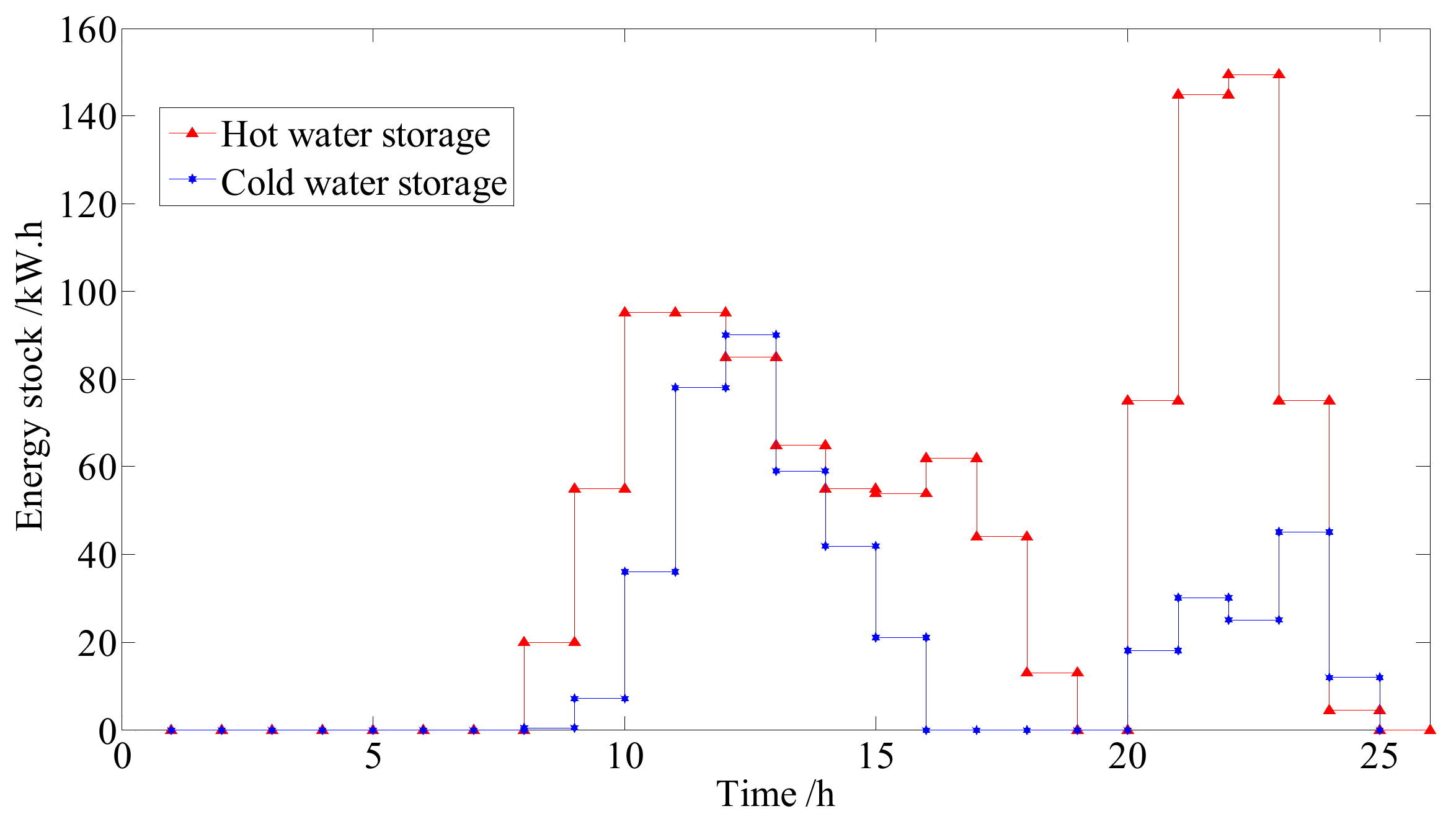
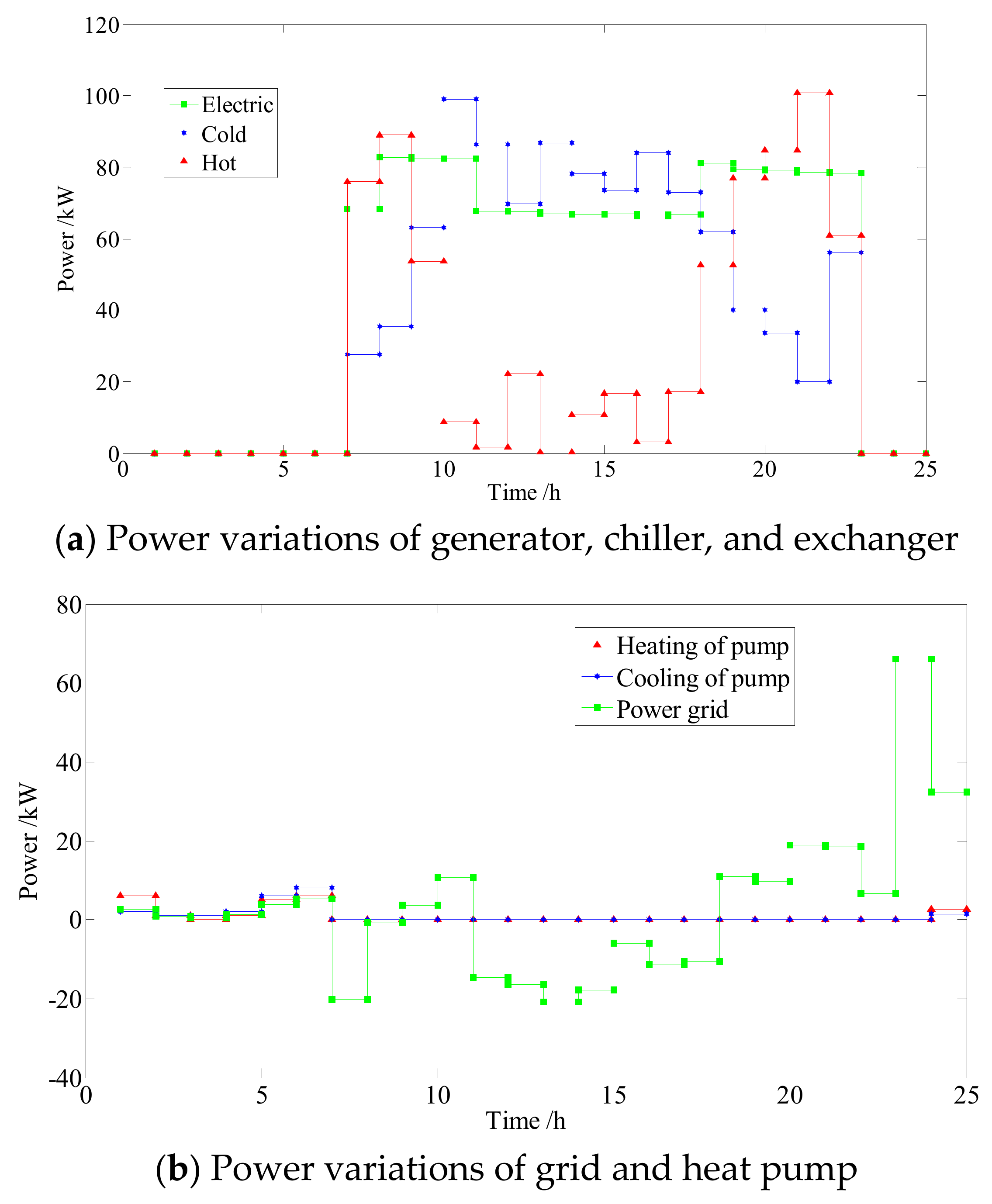
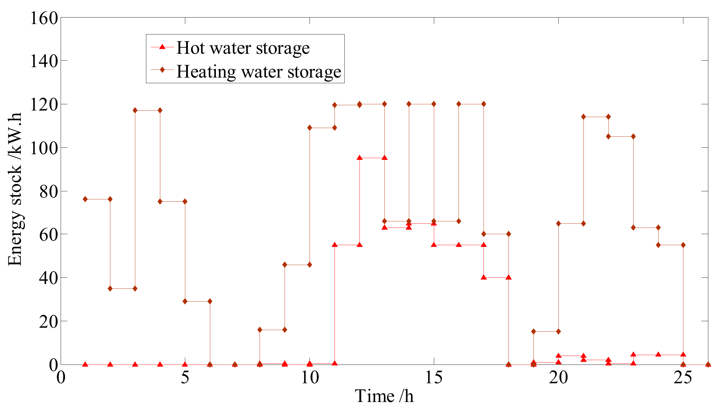
The optimal results obtained using the loads in summer are presented in Figure 7 and Figure 8. The negative power grid output values indicate generator feedback power to the grid.
As shown in Figure 7, the energy storage units store energy when the demand is low and then supply a substantial portion of the energy demand during the peak power consumption periods. As depicted in Figure 8, the generator operates at the load rate of about 80%, although the electrical load fluctuates sharply. The storage units serve to reduce the peaks and fill the valleys, which dramatically improves the energy utilization. Nevertheless, the energy demand tendencies remain observable in the generator operation tracking results. Moreover, the power track of the generator follows the power price of the grid. The generator operates at a high load rate when electrical power is expensive. An appropriate load rate is applied when power is modestly priced. The generator would stop at a low power price.
From 8:00 to 10:00, the generator operated at nearly full capacity, and some extra power was sold to the grid. It can be seen from Table 1 that the operating efficiency at full capacity is lower than the maximum efficiency. However, electrical power is so expensive that it is profitable to sacrifice some efficiency. Moreover, the storage units store considerable energy to prepare for the upcoming phase of peak energy consumption.
From 19:00 to 20:00, the thermal energy demand is low. Due to the high electricity price and large amount of electricity demand, the generator operated at nearly full capacity. Meanwhile, large quantity of thermal energy is stored to handle the next peak of thermal energy consumption.
The generator stopped at 23:00. The subsequent thermal demand can be supplied by the energy stored beforehand. If the generator continues operating, the stored energy would remain unutilized. The generator should stop operating although there was little power demand at 23:00.
In summary, the operation optimization is influenced by three main factors. The most important factor is the power demand, which determines the general trend of the optimization results. The next factor is the price of electricity, which strongly affects the operating state of the generator. The last factor is the dissipation of stored energy, which restricts the energy storage time. These three factors jointly determine the optimization results.
Under the energy demands of a typical day in summer, the operating targets of the CCHP system obtained using dynamic programming and the traditional energy system targets are provided in Table 7. The operating cost is converted into dollars.
The energy efficiency is the proportion of energy consumed by users and the fossil energy consumed by the power station, gas boiler, and CCHP system. The operating cost of the CCHP system is reduced by 40.8% compared to that in the traditional energy system. Furthermore, the fuel energy saving ratio is 22.0% and the carbon emission is decreased by 54.7% in the CCHP system.
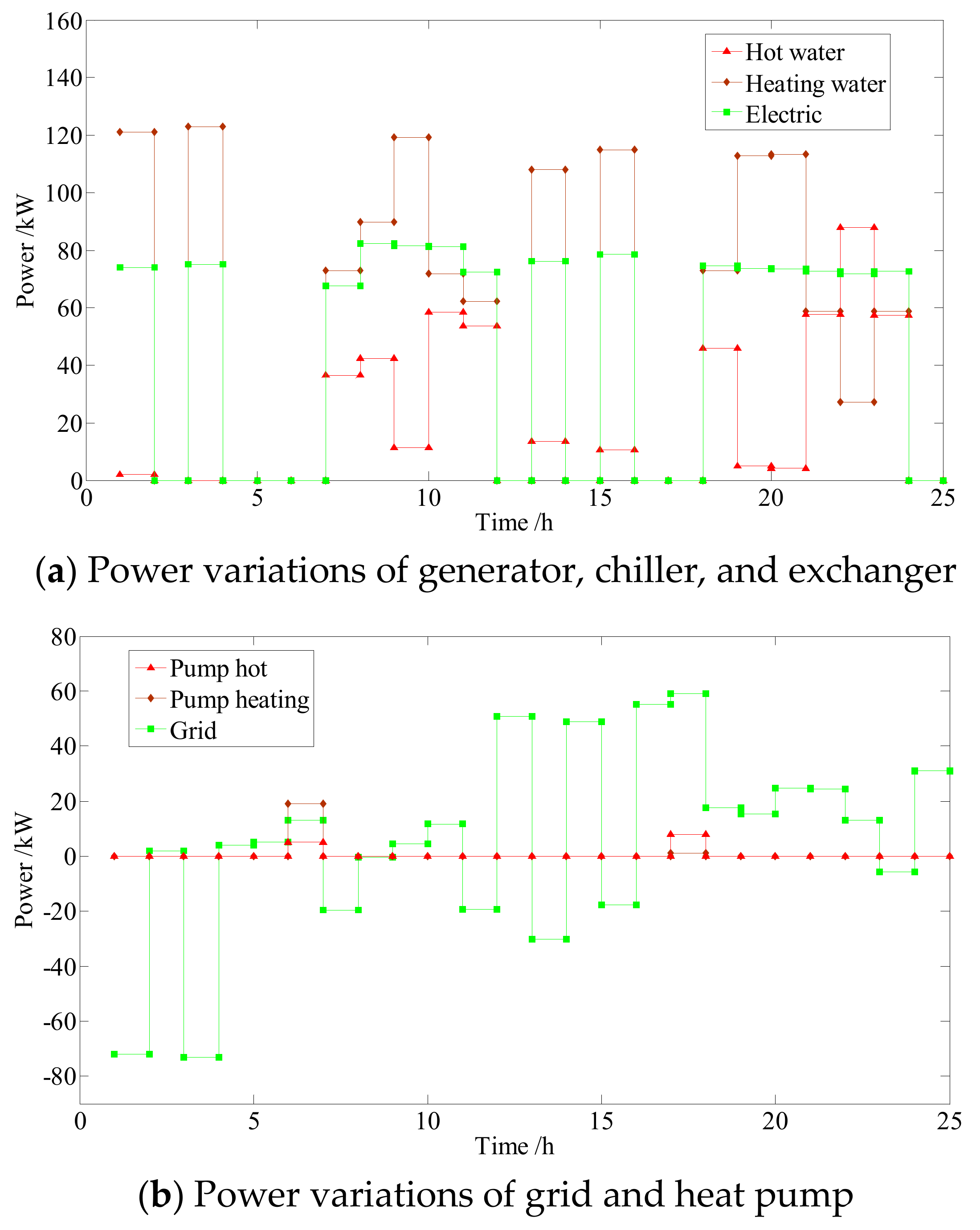
The optimal results obtained considering the loads in winter are presented in Figure 9 and Figure 10.
As mentioned previously, the hot water required by the central air conditioning system to keep the dormitory warm was separated from that consumed by bathing and so on, and the cool storage tank was employed to store this part of the hot water.
Generally, the optimization result under winter conditions is influenced by the three factors discussed for summer conditions. However, a significant characteristic occurs at late night. Unlike in the results obtained for summer, the generator starts at night because the heating load is heavy in winter. Because the electricity is cheap late at night, the generator has to operate at the highest efficiency. Otherwise, it has to stop. Hot water is stored to supply heating. Under the energy demands of a typical day in winter. The operating targets are compared in Table 8.
When compared with the traditional energy system, the operating cost is reduced by 35.8%, the fuel energy saving ratio is 16.7%, and the carbon emission is decreased by 39.5%.
The conclusion can be drawn that this optimization method not only ensures that the optimal operating cost is achieved, but also obviously improves the fuel energy saving and environment protection. Moreover, all the optimizing results were obtained in less than three seconds.
5. Conclusions
In this paper, a CCHP system with storage units was designed. Due to its complex structure and internal coupling relation, especially considering that its operation progress is essentially dynamic, traditional optimizing algorithms have some insufficiencies in optimizing its operating schedule. Recent research has improved the advantages of dynamic programming applied to CCHP system optimization. However, its application to a CCHP system with complex structure needs efficient planning to reduce computation.
In the proposed method, the optimization problem was split into a dynamic problem and an embedded static problem. The dynamic problem reflects the essence of the optimization problem, while the static problem provides the basis of the dynamic problem. Thousands of repeated computations were eliminated in economical optimization by introducing the concept of constant cost and variable cost. Compared to a traditional energy system, the operating cost was reduced by 40.8%, the fuel energy saving ratio was 22.0%, and the carbon emission was decreased by 54.7%. Moreover, the optimization of the whole day of a CCHP system requires about 3 s on an average desktop computer. This is a very short optimization time for a CCHP system with energy storage units. Thus, dynamic programming can be successfully employed to solve the optimization of CCHP system with complex structure.
In addition, the optimizing methodology applied in this paper implies a stochastic dynamic solving framework, which will probably contribute to CCHP system optimization. We have achieved some breakthrough and are trying to employ it in stochastic optimization of CCHP systems considering off-design performance.
Author Contributions
Conceptualization, J.K.; Methodology, J.K.; Software, J.K., F.L.; Resources, C.Z., B.S.; Writing-Review & Editing, B.S.
Funding
This work was supported by the National Natural Science Foundation of China (grant numbers 61733010, 61320106011, 61573224, 61573223) and the Young Scholars Program of Shandong University (grant number 2016WLJH29).
Conflicts of Interest
The authors declare no conflict of interest.
References
- Bilgen, S.; Keleş, S.; Kaygusuz, A.; Sarı, A.; Kaygusuz, A. Global warming and renewable energy sources for sustainable development: A case study in Turkey. Renew. Sust. Energy Rev. 2008, 12, 372–396. [Google Scholar] [CrossRef]
- Wu, D.; Wang, R. Combined cooling, heating and power: A review. Prog. Energy Combust. Sci. 2006, 32, 459–495. [Google Scholar] [CrossRef]
- Guo, L.; Liu, W.; Cai, J.; Hong, B.; Wang, C. A two-stage optimal planning and design method for combined cooling, heat and power microgrid system. Energy Convers. Manag. 2013, 74, 433–445. [Google Scholar] [CrossRef]
- Jradi, M.; Riffat, S. Tri-generation systems: Energy policies, prime movers, cooling technologies, configurations and operation strategies. Renew. Sustain. Energy Rev. 2014, 32, 396–415. [Google Scholar] [CrossRef]
- Liu, M.; Shi, Y.; Fang, F. Combined cooling, heating and power systems: A survey. Renew. Sustain. Energy Rev. 2014, 35, 1–22. [Google Scholar] [CrossRef]
- Bellos, E.; Tzivanidis, C. Optimization of a solar-driven trigeneration system with nanofluid-based parabolic trough collectors. Energies 2017, 10, 848. [Google Scholar] [CrossRef]
- Ju, L.; Tan, Z.; Li, H.; Tan, Q.; Yu, X.; Song, X. Multi-objective operation optimization and evaluation model for CCHP and renewable energy based hybrid energy system driven by distributed energy resources in China. Energy 2016, 111, 322–340. [Google Scholar] [CrossRef]
- Palomba, V.; Ferraro, M.; Frazzica, A.; Vasta, S.; Sergi, F.; Antonucci, V. Experimental and numerical analysis of a SOFC-CHP system with adsorption and hybrid chillers for telecommunication applications. Appl. Energy 2018, 216, 620–633. [Google Scholar] [CrossRef]
- Wei, D.; Chen, A.; Sun, B.; Zhang, C. Multi-objective optimal operation and energy coupling analysis of combined cooling and heating system. Energy 2016, 98, 296–307. [Google Scholar] [CrossRef]
- Zeng, R.; Li, H.; Liu, L.; Zhang, X.; Zhang, G. A novel method based on multi-population genetic algorithm for CCHP–GSHP coupling system optimization. Energy Convers. Manag. 2015, 105, 1138–1148. [Google Scholar] [CrossRef]
- Song, X.; Liu, L.; Zhu, T.; Zhang, T.; Wu, Z. Comparative analysis on operation strategies of CCHP system with cool thermal storage for a data center. Appl. Therm. Eng. 2016, 108, 680–688. [Google Scholar] [CrossRef]
- Gopisetty, S.; Treffinger, P. Generic combined heat and power (CHP) model for the concept phase of energy planning process. Energies 2016, 10, 11. [Google Scholar] [CrossRef]
- Lozano, M.; Ramos, J.; Carvalho, M.; Serra, L. Structure optimization of energy supply systems in tertiary sector buildings. Energy Build. 2009, 41, 1063–1075. [Google Scholar] [CrossRef]
- Moussawi, H.; Fardoun, F. Louahlia-Gualous, H. Review of tri-generation technologies: Design evaluation, optimization, decision-making, and selection approach. Energy Convers. Manag. 2016, 120, 157–196. [Google Scholar] [CrossRef]
- Han, B.; Cheng, W.; Li, Y.; Nian, Y. Thermodynamic analysis of heat driven Combined Cooling Heating and Power system (CCHP) with energy storage for long distance transmission. Energy Convers. Manag. 2017, 154, 102–117. [Google Scholar] [CrossRef]
- Li, G.Z.; Wang, R.; Zhang, T.; Ming, M.J. Multi-objective optimal design of renewable energy integrated CCHP system using PICEA-g. Energies 2018, 11, 743. [Google Scholar]
- Sigarchian, S.; Malmquist, A.; Martin, V. Design optimization of a small-scale polygeneration energy system in different climate zones in Iran. Energies 2018, 11, 1115. [Google Scholar] [CrossRef]
- Wang, J.; Sui, J.; Jin, H. An improved operation strategy of combined cooling heating and power system following electrical load. Energy 2015, 85, 654–666. [Google Scholar] [CrossRef]
- Zeng, R.; Li, H.; Jiang, R.; Liu, L.; Zhang, G. A novel multi-objective optimization method for CCHP–GSHP coupling systems. Energy. Build. 2016, 112, 140–158. [Google Scholar] [CrossRef]
- Wang, F.; Zhou, L.; Ren, H.; Liu, X. Search improvement process-chaotic optimization-particle swarm optimization-elite retention strategy and improved combined cooling-heating-power strategy based two-time scale multi-objective optimization model for stand-alone microgrid operation. Energies 2017, 10, 1936. [Google Scholar] [CrossRef]
- Bao, Z.; Zhou, Q.; Yang, Z.; Yang, Q.; Xu, L.; Wu, T. A multi time-scale and multi energy-type coordinated microgrid scheduling solution. IEEE Trans. Power Syst. 2015, 30, 2257–2276. [Google Scholar] [CrossRef]
- Shaneb, O.; Taylor, P.; Coates, G. Optimal online operation of residential μCHP systems using linear programming. Energy Build. 2012, 44, 17–25. [Google Scholar] [CrossRef]
- Bischi, A.; Taccari, L.; Martelli, E.; Amaldi, E.; Manzolini, G.; Silva, P.; Campanari, S.; Macchi, E. A detailed MILP optimization model for combined cooling, heat and power system operation planning. Energy 2014, 74, 12–26. [Google Scholar] [CrossRef]
- Gu, W.; Wang, Z.; Wu, Z.; Luo, Z.; Tang, Y.; Wang, J. An online optimal dispatch schedule for CCHP microgrids based on model predictive control. IEEE Trans. Smart Grid 2017, 8, 2332–2342. [Google Scholar] [CrossRef]
- Luo, Z.; Wu, Z.; Li, Z.; Cai, H.; Li, B.; Gu, W. A two-stage optimization and control for CCHP microgrid energy management. Appl. Therm. Eng. 2017, 125, 513–522. [Google Scholar] [CrossRef]
- Smith, A.D.; Mago, P.J.; Fumo, N. Benefits of thermal energy storage option combined with CHP system for different commercial building types. Sustain. Energy Technol. Assess. 2013, 1, 3–12. [Google Scholar] [CrossRef]
- Cho, H.; Smith, A.; Mago, P. Combined cooling, heating and power: A review of performance improvement and optimization. Appl. Energy 2014, 136, 168–185. [Google Scholar] [CrossRef]
- Facci, A.; Andreassi, L.; Ubertini, S. Optimization of CHCP (combined heat power and cooling) systems operation strategy using dynamic programming. Energy 2014, 66, 387–400. [Google Scholar] [CrossRef]
- Facci, A.; Ubertini, S. Meta-heuristic optimization for a high-detail smart management of complex energy systems. Energy Convers. Manag. 2018, 160, 353. [Google Scholar] [CrossRef]
- Mago, P.; Fumo, N.; Chamra, L. Performance analysis of CCHP and CHP systems operating following the thermal and electric load. Int. J. Energy Res. 2009, 33, 852–864. [Google Scholar] [CrossRef]
- Mancarella, P.; Chicco, G. Assessment of the greenhouse gas emissions from cogeneration and trigeneration systems. Part II: Analysis techniques and application cases. Energy 2008, 33, 418–430. [Google Scholar] [CrossRef]
- Office of Energy Efficiency and Renewable Energy. Commercial reference buildings. Available online: http://energy.gov/eere/buildings/commercial-reference-buildings (accessed on 13 November 2012).
- Li, C.; Shi, Y.; Huang, X. Sensitivity analysis of energy demands on performance of CCHP system. Energy Convers. Manag. 2008, 49, 3491–3497. [Google Scholar] [CrossRef]
Figure 1.
CCHP system.

Figure 2.
Arrangement of .

Figure 3.
Shortest path model.

Figure 4.
Dynamic programming flow diagram.

Figure 5.
Relationship between and for different .

Figure 6.
Energy demand time traces.

Figure 7.
Changes in energy storage under summer conditions.

Figure 8.
Power variations of system components under summer conditions.

Figure 9.
Changes in energy storage under winter conditions.

Figure 10.
Power variations of system components under winter conditions.


Table 1.
Performance of a small naturally aspirated internal combustion engine generator [9].
Table 1.
Performance of a small naturally aspirated internal combustion engine generator [9].
| PLR | |||||
|---|---|---|---|---|---|
| 0.000 | 0.0000 | 0.0000 | 0.5628 | 0.2764 | 0.1608 |
| 0.100 | 0.1020 | 0.7700 | 0.5227 | 0.2955 | 0.1818 |
| 0.200 | 0.1809 | 0.7800 | 0.5031 | 0.3006 | 0.1963 |
| 0.300 | 0.2250 | 0.8200 | 0.4903 | 0.3097 | 0.2000 |
| 0.400 | 0.2637 | 0.8400 | 0.4865 | 0.3108 | 0.2027 |
| 0.500 | 0.2871 | 0.8600 | 0.4861 | 0.3125 | 0.2014 |
| 0.600 | 0.3085 | 0.8750 | 0.4892 | 0.3237 | 0.1870 |
| 0.700 | 0.3184 | 0.8850 | 0.4818 | 0.3285 | 0.1898 |
| 0.800 | 0.3184 | 0.9000 | 0.4745 | 0.3285 | 0.1971 |
| 0.900 | 0.3039 | 0.9100 | 0.4507 | 0.3169 | 0.2324 |
| 1.000 | 0.2886 | 0.9200 | 0.4336 | 0.3147 | 0.2517 |
Note: is the load rate, and and are the efficiencies of the generator and internal combustion engine, respectively. and are the energy ratios corresponding to the jacket water and exhaust, respectively. represents the heat loss rate.
| Parameters | Values |
|---|---|
| Generator capacity | 90 kW |
| Efficiency of domestic hot water heat exchanger | 0.95 |
| Rated efficiency of absorption chiller | 0.8 |
| Efficiency of exhaust heat exchanger | 0.8 |
| Energy loss ratio of jacket water in exhaust heat exchanger | 0.2 |
| Heating value of natural gas Q | 35,500 kJ/m3 |
| Price of natural gas | 2 ¥/m3 |
Table 3.
Description of the simulated building [32].
Table 3.
Description of the simulated building [32].
| Parameter | Data |
|---|---|
| Location | Baltimore |
| Area | 4014 m2 |
| Volume | 11,622 m3 |
| Gross wall area | 1695 m2 |
| Window glass area | 184 m2 |
| Lights (on average) | 16.10 W/m2 |
| Elec plug and process (on average) | 12.16 W/m2 |
| People | 254 people |
| Parameters | Values |
|---|---|
| Rated COP for electrically driven heat pump , | 3 |
| Cold storage coefficient | 0.97 |
| Heat storage coefficient | 0.95 |
| Capacity of heat storage unit | 150 |
| Capacity of cold storage unit | 120 |
| Rated power of generator | 90 kW |
| Capacity of absorption chiller | 100 kW |
Table 5.
Constant parameters of a traditional energy system [9].
Table 5.
Constant parameters of a traditional energy system [9].
| Parameters | Values |
|---|---|
| Efficiency of Power Plant | 0.35 |
| Efficiency of power transmission | 0.92 |
| COP of electrically driven air conditioning system | 3 |
| Efficiency of gas boiler | 0.88 |
Table 6.
Parameters of natural gas and coal [9].
Table 6.
Parameters of natural gas and coal [9].
| Type of Fuel | Heating Value | CO2 Emission When Thoroughly Burned |
|---|---|---|
| Coal | 29,300 kJ/kg | 2.69 kg/kg |
| Natural gas | 35,500 kJ/m3 | 1.96 kg/m3 |
Table 7.
Targets comparison of a whole day of operation in summer.
| Operating Target | Operating Cost ($) | CO2 Emission (kg) | Fuel Consumption (MJ) |
|---|---|---|---|
| Traditional energy system | 254.1 | 2038.7 kg | 20,464.92 |
| CCHP system | 150.4 | 924.2 kg | 15,953.76 |
| Variation | 103.7 | 1114.5 kg | 4511.16 |
| Rate of change | 40.8% | 54.7% | 22.0% |
Table 8.
Targets comparison of a whole day of operation in winter.
| Operating Target | Operating Cost ($) | CO2 Emission (kg) | Fuel Consumption (MJ) |
|---|---|---|---|
| Traditional energy system | 247.4 | 1895.8 | 21,289.68 |
| CCHP system | 158.9 | 1147.1 | 17,753.76 |
| Variation | 88.5 | 748.7 | 3535.92 |
| Rate of change | 35.8% | 39.5% | 16.7% |
© 2018 by the authors. Licensee MDPI, Basel, Switzerland. This article is an open access article distributed under the terms and conditions of the Creative Commons Attribution (CC BY) license (http://creativecommons.org/licenses/by/4.0/).
Share and Cite
MDPI and ACS Style
Kuang, J.; Zhang, C.; Li, F.; Sun, B. Dynamic Optimization of Combined Cooling, Heating, and Power Systems with Energy Storage Units. Energies 2018, 11, 2288. https://doi.org/10.3390/en11092288
AMA Style
Kuang J, Zhang C, Li F, Sun B. Dynamic Optimization of Combined Cooling, Heating, and Power Systems with Energy Storage Units. Energies. 2018; 11(9):2288. https://doi.org/10.3390/en11092288
Chicago/Turabian StyleKuang, Jiyuan, Chenghui Zhang, Fan Li, and Bo Sun. 2018. "Dynamic Optimization of Combined Cooling, Heating, and Power Systems with Energy Storage Units" Energies 11, no. 9: 2288. https://doi.org/10.3390/en11092288
Note that from the first issue of 2016, this journal uses article numbers instead of page numbers. See further details here.