Abstract
The use of salt rock for underground radioactive waste disposal facilities requires a comprehensive analysis of the creep-damage process in salt rock. A computer-controlled creep setup was employed to carry out a creep test of salt rock that lasted as long as 359 days under a constant uniaxial stress. The acoustic emission (AE) space-time evolution and energy-releasing characteristics during the creep test were studied in the meantime. A new creep-damage model is proposed on the basis of a fractional derivative by combining the AE statistical regularity. It indicates that the AE data in the non-decay creep process of salt rock can be divided into three stages. Furthermore, the authors propose a new creep-damage model of salt rock based on a fractional derivative. The parameters in the model were determined by the Quasi-Newton method. The fitting analysis suggests that the new creep-damage model provides a precise description of full creep regions in salt rock.
1. Introduction
Salt rock is widely used in energy storage and radioactive waste disposal in underground engineering facilities. It is hard to predict their mechanical behavior during a long design life [1,2,3,4,5]. Thus, research on the creep-damage of salt rock is significant to avoid the loss of effective storage space in underground cavities.
The full creep regions of salt rock can be divided into three stages: The transient creep region (the primary region), the steady-state creep region (the secondary region), and the accelerated creep region (the tertiary region) [6]. Many efforts have been expanded on analyzing creep-damage features through mathematical modeling. Passaris has studied the creep of salt rock by using a three element model. The results indicated that the three-element model provided a precise description of creep deformation [7]. Ghavidel performed axial creep experiments of salt rock under different temperatures. The theoretical analysis revealed that the Burgers model is accurate in describing the characteristics of salt rock in different temperatures [8]. Hou and Lux conducted a creep experiment of salt rock and proposed the Hou-Lux creep constitutive model under the theory of strain hardening and recovery, damage and damage healing [9]. The Hou-Lux model was applied to predict the time-dependent deformation of salt rock in the Excavation Disturbed Zone (EDZ) of a 37-year-old underground cavity [10].
In addition, fractional calculus is helpful to propose the creep constitutive models as it has advantages in explicating the accumulation process of internal stress, reducing the parameters in a constitutive model and representing the nonlinear characteristics. Zhou has proposed a creep constitutive model of salt rock based on a fractional derivative by replacing a Newtonian dashpot in the classical Nishihara model with the fractional derivative Abel dashpot and found that the predicted results were consistent with the experimental data [11]. Wu improved the Maxwell creep model and established a constitutive model of salt rock based on variable-order fractional derivatives [12]. By combining ultrasonic testing (UT), Zhou introduced a variable-viscosity Abel dashpot in a new creep constitutive model [13]. However, the UT could only reflect two-dimensional (2D) damage information inside of the salt rock.
The acoustic emission (AE) test provides a more precise three-dimensional (3D) description of damage during the creep process as it records information at any given point inside the salt rock. It is widely used for rock damage testing both in the laboratory and situ. Lavrov performed AE experiments in clay to study the damage evolution of a boom clay specimen during uniaxial compression. These experiments indicated that, as is the case with salt rock, clay also shows the Kaiser effect in AE with Felicity ratios around unity [14]. Hardy collected the AE signals during a uniaxial compression experiment. This research suggested that the number of accumulated AE signals follows a linear relationship with the axial strain [15]. Kong used AE location technology to study the multifractal characteristics of coal. These studies revealed the process of crack evolution of coal and the generation mechanism of AEs [16]. Zhang performed AE experiments with granite samples and studied the relationship between the AE temporal-spatial distribution and the fractal dimension. It suggested that the characteristics of the AE temporal-spatial distribution can be quantitatively described by the fractal dimension [17].
In this paper, the authors completed uniaxial compression experiments of salt rock, which lasted for 359 days, and analyzed the AE features. These experiments indicated that the AE data in the unsteady creep process of salt rock can be divided into three stages. Furthermore, the parameters of a new creep-damage model were determined by the Quasi-Newton method. The fitting analysis suggested that the creep-damage model, based on a fractional derivative in this paper, provided a precise description of the full creep regions in salt rock.
2. Methods
The salt rock specimen used in the uniaxial compression experiments was taken from a salt mine in Pingdingshan City, Henan Province, Central China. It was drilled from the PT Well No.1 at a depth of 1719 m below the ground’s surface. The main surrounding rock mass had a salt content up to 98.14–98.71%. The cylindrical salt rock specimen (No. 7-27-17) used in the uniaxial experiments was processed on a dry lathe and prepared with the required dimensions of 80 mm in diameter and 160 mm in length. According to other experiments using salt samples drilled at the same place, the long-term strength is about 12 to 14 MPa. Then, the axial load was set to be a constant value of 17 MPa so that the accelerated creep curve can be obtained.
The uniaxial compression tests were carried out at Sichuan University using a computer-controlled creep setup, with a uniaxial load in the range of 0–600 kN [11]. A three-dimensional real-time monitor and display system (model: PCI-2), manufactured by the American Physical Acoustics Corporation, was used to monitor the AE signals (Figure 1). The preamplifier gain was 40 dB, and the threshold value was set at 35 dB in order to eliminate background noise [18]. Eight AE sensors were installed symmetrically in the radial direction along the cylinder’s surface and the distance from the sensor to the nearest end surface was about 1 cm (Figure 1). The system was able to capture and display the acoustic emissions during the whole rock damage and failure process. To get a better effect in receiving AE signals, the AE sensors were isolated from the specimen by thin Vaseline plates. The experiment lasted from 10 May 2013 to 4 May 2014. During the whole failure process of salt rock, the temperature was kept at 22 .
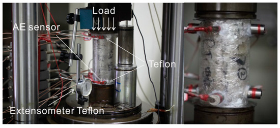
Figure 1.
Experimental setup of the creep test of salt rock.
3. Experiment Results and Discussion
The salt rock exhibited expansion failure during the creep experiment without a confining pressure (Figure 2). The fractures in the salt rock specimen were mainly concentrated in the middle part of the specimen. A mass of penetrative cranny and discrete salt gains was clearly observed after failure.
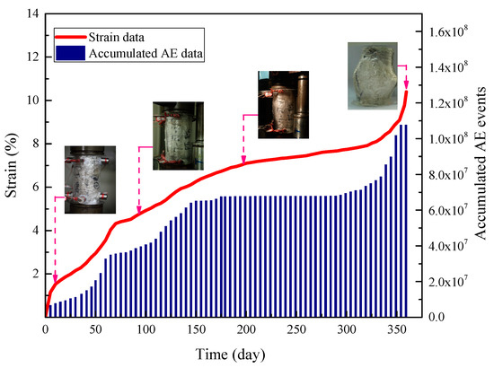
Figure 2.
The deformation characteristics of salt rock during the creep process.
The authors analyzed the strain rate to further investigate the relationship between deformation and the AE spatial distribution during the creep process. The analysis indicated that the creep process can be divided into three stages (Figure 3). During Stage I, the strain hardening effect was stronger than the strain recovery effect at room temperature, so the strain rate curve showed a downtrend. This stage ends after about 179 days. Then, the strain rate remained steady at a relatively low level of 10−9/s until 319 days. This stage was considered to be the steady stage of creep. After 319 days, the axial strain rate sharply increased, which means that the creep process entered the accelerated stage (Stage III). The salt rock quickly deformed until failure.
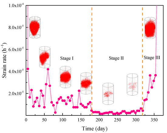
Figure 3.
The strain rate and spatial distribution of AE events. The inset images show the spatial distribution characteristics of AE events in the different creep stages.
The inset images in Figure 3 also illustrate the spatial distribution of AE events during the full creep process. The red points represent the locations of acoustic emission events and each point corresponds to a fracture surface or volume in physical space. It revealed that the AE events were mainly focused on the middle part of the specimen during the loading process. The AE spatial distribution corresponded to the damaged parts of the salt rock, shown in Figure 2. During Stage I, AE events were relatively extensive in the middle portion and covered a comparatively large volume of the specimen. Then, the number of AE events markedly decreased and remained stable at a low level for about 90 days. Finally, the AE events rapidly increased and spread through the whole specimen.
The creep curves of full regions and their corresponding AE events can be observed in Figure 4. During Stage I, the AE events number and the released energy from the salt rock sample was at a relatively high level and fluctuated greatly during the primary region (Figure 4a,b). At 64 days, the AE rate reached a peak of 8.34 × 10⁴/h. Meanwhile, the released energy also reached a peak of 3.16 × 10⁻⁶ J. The irregular fluctuation of the AE rate in this stage was mainly caused by the inhomogeneous distribution of different components in natural salt rock.
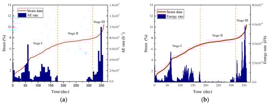
Figure 4.
The curves for the AE count rate and released energy: (a) AE count rate vs. strain-time curve; (b) Released energy rate vs. strain-time curve.
The AE numbers and released energy of salt rock in the steady stage (Stage II) was rather small in contrast to the initial stage. It appeared that the fracture hardly grew so that only a few AE signals could be generated and received. During Stage III, the number of AE events and released energy rapidly increased to the maximum value. The sample continued to be damaged as the strain energy was released and the strain rate accelerated until failure. The ultimate deformation value of salt rock was 10.396 mm. Further, it was be found that the number of AE events and released energy of salt rock almost had the same trend (Figure 4).
4. Creep-Damage Model of Salt Rock Based on a Fractional Derivative
The creep behavior of salt rock can be divided into the steady creep process and the unsteady creep process. The former usually happens when an external load is under the long-time strength of the salt rock. The creep rate gradually decreased to a small constant close to zero under ideal conditions. The unsteady creep process happens when an external load is greater than or equal to the long-time strength of the salt rock. A typical unsteady creep process is usually divided into three stages, which are named initial transient creep period, the steady-state period, and the tertiary stage (an unsteady state period). The constitutive model in this paper aimed to study the unsteady creep process of salt rock.
4.1. The Maxwell Model
The Maxwell model is the simplest viscoelasticity model and the Maxwell model is set up by putting a spring and a dashpot together in a series. The Maxwell constitutive model is given as
where , is the elasticity modulus, is the viscosity coefficient, the initial condition is when , represents the instantaneous strain of salt rock. It can only describe the ideal fluid features of salt rock.
However, the creep behavior of salt rock is the interactions among elastic, viscoelastic and viscoplastic behavior. Thus, the Maxwell model should be improved in order to get a better explanation on creep behavior of natural salt rocks.
4.2. The Abel Dashpot: A Fractional Derivative Element
A typical application of fractional calculus is the Abel dashpot, which is a fractional derivative description of the Newtonian dashpot. The constitutive relation of the Abel dashpot is given by [11,13]
where is the viscosity coefficient and indicates the fractional derivative. The Abel dashpot in Equation (2) can be used to describe both the Newtonian dashpot in the special case of , representing an ideal fluid and a spring in the special case of , representing an ideal solid. The Abel dashpot exhibits characteristics of both a spring and the Newtonian dashpot and eliminates the limitation of an element being solely either a spring or the Newtonian dashpot.
Considering in Equation (3), taking the fractional integral calculation of Equation (2) on the basis of the Riemann-Liouville operator, we obtain
where Equation (3) denotes the creep strain characterized by the Abel dashpot. More details on the Abel dashpot can be found in Zhou [11,13].
4.3. Maxwell Model Based on a Fractional Derivative
The creep-damage behavior of salt rock has been studied through indoor creep experiments, which lasted for 359 days. By replacing the Newtonian dashpot in the Maxwell model with the Abel dashpot, the new constitutive relation of the Maxwell creep model (Figure 5), based on a fractional derivative, is given by
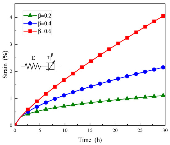
Figure 5.
Creep strain of the Maxwell model based on a fractional derivative given by: σ = 20 MPa and ηβ = 8 GPa · h.
Equation (4) denotes the creep strain characterized by the Abel dashpot. According to other experiments using salt samples drilled at the same place, the long-term strength is about 12 to 14 MPa. To make sure that the accelerated creep finally occurred during the experiment, the axial stress was greater than the long-term strength. So, according to accumulated experiences, substituting and into Equation (4), one finds a series of creep curves under different derivative orders, (Figure 5). It can be easily observed that the Maxwell creep model, based on a fractional derivative, has advantages in describing the characteristics of the decay creep process.
4.4. The Creep-Damage Model Based on a Fractional Derivative
Many researchers have considered the creep of salt rock as a decay creep process, when the accelerating creep stage is ignored, which was caused by damage accumulation. Thus, they usually ignore the damage in the first two creep stages when establishing the constitutive model. But according to the discontinuity in natural salt rock, the damage actually existed since the beginning of the experiment and directly affected the whole creep process. As such, when considering damage during the full creep region, the total creep deformation can be concluded as the combination of two parts: primary and steady creep strains (the decay creep process without damage) and the strain induced by the damage . Thus, the total creep deformation is given as
where is the total strain of creep.
By using the Maxwell creep model, based on a fractional derivative, to define the primary and steady creep strain, , the constitutive relation of and is given as [9]
where is the elasticity modulus, is the viscosity coefficient, are material coefficients, and is the damage factor, .
The accumulated energy of AE events was used to evaluate the damage. Considering the data from the 5th sensor, the damage variable, , can be defined as
where is the strain of the specimen at time, , is the total strain, and is the energy density of the 5th sensor at the loading level of .
By using acoustic emission data from the uniaxial compression test, the energy density , relative to the strain curve of the specimen, is plotted in Figure 6. The damage variable, , at any creep strain can be calculated by integration methods. According to the least square method, the relation between the damage variable, , and strain at time, , can be defined as
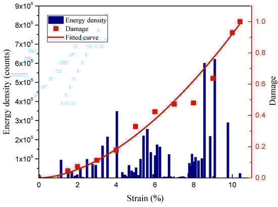
Figure 6.
Curves of energy density and damage relative to the strain of the salt rock sample.
All units are calculated using the International System of Units. So, the values of and from the fitted curve of damage variables are 0.0161 and 1.7572, respectively. It can be seen from the global evolution of damage that the damage increases slowly and steadily at the beginning of the loading procedure and then increases rapidly towards the end.
Synthetically, the creep-damage model, based on a fractional derivative, is given by
4.5. Parameter Determination by Fitting Analysis
The efficacy of the creep-damage model, based on a fractional derivative, is dependent on its ability to adequately fit experimental data. Using the experimental data of salt rock creep under uniaxial compression, the parameters of the creep-damage model in Equation (10) were determined by the Quasi-Newton method (Figure 7, Table 1). It is indicated that the creep-damage model, based on a fractional derivative, proposed in this paper, can adequately represent the creep deformation of salt rock and accord with the experimental data better than the results estimated by the Maxwell model.
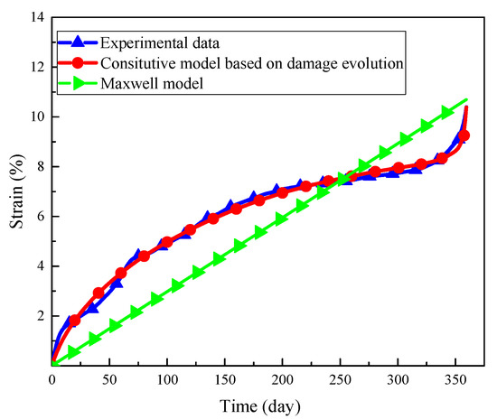
Figure 7.
Experimental data and fitting curves.

Table 1.
Parameters determined by a fitting analysis based on creep tests of salt rock.
5. Conclusions
By replacing the Newtonian dashpot in the classical Maxwell model with the variable-viscosity Abel dashpot, a new creep-damage constitutive model was proposed with AE statistical regularity. The parameters of the new creep-damage model were determined by the Quasi-Newton method.
The results show that the creep deformation reflected the three stages of characteristics of a non-decay creep process. Meanwhile, the AE signals could also be divided into three obvious different stages. The distribution of the acoustic emission signal agreed well with the location where the deformation or growing fractures appeared in the salt rock. Furthermore, the cumulated AE events and released energy showed the same trend.
By considering the damage factor during the whole process of creep, a new mathematical model, which is named the creep-damage model based on a fractional derivative was proposed. In addition, the fitting analysis suggested that the creep-damage model based on a fractional derivative, in this paper, provided a precise description of the full creep regions in salt rock.
Author Contributions
H.Z. and D.L. contributed to the concept, results explanation and writing of the paper. D.L. and Y.Z. performed the experiments and analyzed the data. G.L. and D.X. contributed to the formal analysis. Supervision, Project Administration, and Funding Acquisition, H.Z.
Funding
This work was funded by the National Natural Science Foundation of China (51674266), and the State Key Research Development Program of China (2016YFC0600704) and the Yueqi Outstanding Scholar Program of CUMTB (2017A03). The financial supports are gratefully acknowledged.
Conflicts of Interest
The authors declare no competing interests.
References
- Li, Y.P.; Yang, C.H.; Daemen, J.J.K.; Yin, X.Y. A new Cosserat-like constitutive model for bedded salt rocks. Int. J. Numer. Anal. Meth. Geomech. 2009, 33, 1691–1720. [Google Scholar] [CrossRef]
- Adolfsson, K.; Enelund, M.; Olsson, P. On the fractional order model of viscoelasticity. Mech. Time-Depend. Mater. 2005, 9, 15–34. [Google Scholar] [CrossRef]
- Bagley, R.L.; Torvik, P.J. Fractional calculus in the transient analysis of viscoelastically damped structures. AIAA J. 1985, 23, 918–925. [Google Scholar] [CrossRef]
- Jin, J.; Cristescu, N.D. An elastic/viscoplastic model for transient creep of rock salt. Int. J. Plast. 1988, 14, 85–107. [Google Scholar] [CrossRef]
- Li, Y.P.; Liu, W.; Yang, C.H.; Daemen, J.J.K. Experimental investigation of mechanical behavior of bedded rock salt containing inclined interlayer. Int. J. Rock Mech. Min. Sci. 2014, 69, 39–49. [Google Scholar] [CrossRef]
- Cai, M.F. Rock Mechanics and Engineering; Bejing Science Press: Beijing, China, 2006. [Google Scholar]
- Passaris, E.K.S. The rheological behavior of rock salt as determined in an in situ pressurized test cavity. In Proceedings of the 4th Conference on International Society for Rock Mechanics, Montreux, Switzerland, 2–8 September 1979; pp. 257–264. [Google Scholar]
- Ghavidel, N.A.; Nazem, A.; Heidarizadeh, M.; Moosavi, M.; Memarian, H. Identification of rheological behavior of salt rock at elevated temperature, case study: Gachsaran evaporative formation. In Proceedings of the SRM European Regional Symposium EUROCK 2014, Vigo, Spain, 27–29 May 2014. [Google Scholar]
- Hou, Z.M.; Lux, K.H. A constitutive model for rock salt including structural damages as well as practice-oriented applications. In Proceedings of the 5th Conference on Mechanical Behaviour of Salt, Bucharest, Romania, 9–11 August 1999; pp. 151–169. [Google Scholar]
- Hou, Z.M. Mechanical and hydraulic behaviour of salt in the excavation disturbed zone around underground facilities. Int. J. Rock Mech. Min. Sci. 2003, 40, 725–738. [Google Scholar] [CrossRef]
- Zhou, H.W.; Wang, C.P.; Han, B.B.; Duan, Z.Q. A creep constitutive model for salt rock based on fractional derivatives. Int. J. Rock Mech. Min. Sci. 2011, 48, 116–121. [Google Scholar] [CrossRef]
- Wu, F.; Liu, J.F.; Wang, J. An improved maxwell creep model for rock based on variable-order fractional derivatives. Environ. Earth Sci. 2015, 73, 6965–6971. [Google Scholar] [CrossRef]
- Zhou, H.W.; Wang, C.P.; Mishnaevsky, L., Jr.; Duan, Z.Q.; Ding, J.Y. A fractional derivative approach to full creep regions in salt rock. Mech. Time-Depend. Mater. 2013, 17, 413–425. [Google Scholar] [CrossRef]
- Lavrov, A.; Vervoort, A.; Filimonov, Y.; Wevers, M.; Mertens, J. Acoustic emission in host-rock material for radioactive waste disposal: Comparison between clay and rock salt. Bull Eng. Geol. Environ. 2002, 61, 379–387. [Google Scholar] [CrossRef]
- Hardy, H.R. Acoustic emission in salt during incremental creep tests. In Proceedings of the 5th Conference on Mechanical Behaviour of Salt, Bucharest, Romania, 9–11 August 1999. [Google Scholar]
- Kong, X.G.; Wang, E.Y.; He, X.Q.; Li, Z.; Li, D.; Liu, Q. Multifractal characteristics and acoustic emission of coal with joints under uniaxial loading. Fractals 2017, 25, 1750045. [Google Scholar] [CrossRef]
- Zhang, R.; Dai, F.; Gao, M.Z.; Xu, N.W. Fractal analysis of acoustic emission during uniaxial and triaxial loading of rock. Int. J. Rock Mech. Min. Sci. 2015, 79, 241–249. [Google Scholar] [CrossRef]
- Xie, H.P.; Liu, J.F.; Ju, Y.; Li, J.; Xie, L.Z. Fractal property of spatial Distribution of acoustic emissions during the failure process of bedded rock salt. Int. J. Rock Mech. Min. Sci. 2011, 48, 1344–1351. [Google Scholar] [CrossRef]
© 2018 by the authors. Licensee MDPI, Basel, Switzerland. This article is an open access article distributed under the terms and conditions of the Creative Commons Attribution (CC BY) license (http://creativecommons.org/licenses/by/4.0/).