Article

An Ant Colony Optimized MPPT for Standalone Hybrid PV-Wind Power System with Single Cuk Converter

by
Neeraj Priyadarshi
1,*,
Vigna K. Ramachandaramurthy
2,
Sanjeevikumar Padmanaban
3,* and
Farooque Azam
4
1
Department of Electrical Engineering, Birsa Institute of Technology (Trust), Ranchi 835217, India
2
Institute of Power Engineering, Department of Electrical Power Engineering, Universiti Tenaga Nasional, Kajang 43000, Malaysia
3
Department of Energy Technology, Aalborg University, 6700 Esbjerg, Denmark
4
School of Computing & Information Technology, REVA University, Bangalore 560064, India
*
Authors to whom correspondence should be addressed.
Energies 2019, 12(1), 167; https://doi.org/10.3390/en12010167
Submission received: 1 September 2018 / Revised: 10 September 2018 / Accepted: 18 September 2018 / Published: 4 January 2019
(This article belongs to the Special Issue Power Electronics 2018)

Abstract

:
This research work explains the practical realization of hybrid solar wind-based standalone power system with maximum power point tracker (MPPT) to produce electrical power in rural places (residential applications). The wind inspired Ant Colony Optimization (ACO)-based MPPT algorithm is employed for the purpose of fast and accurate tracking power from wind energy system. Fuzzy Logic Control (FLC) inverter controlling strategy is adopted in this presented work compared to classical proportional-integral (PI) control. Moreover, single Cuk converter is operated as impedance power adapter to execute MPPT functioning. Here, ACO-based MPPT has been implemented with no voltage and current extra circuit requirement compared to existing evolutionary algorithms single cuk converter is employed to improve conversion efficiency of converter by maximizing power stages. DC-link voltage can be regulated by placing Cuk converter Permanent Magnet Synchronous Generator (PMSG) linked rectifier and inverter. The proposed MPPT method is responsible for rapid battery charging and gives power dispersion of battery for hybrid PV-Wind system. ACO-based MPPT provides seven times faster convergence compared to the particle swarm optimization (PSO) algorithm for achievement of maximum power point (MPP) and tracking efficiency. Satisfactory practical results have been realized using the dSPACE (DS1104) platform that justify the superiority of proposed algorithms designed under various operating situations.

1. Introduction

Because of abounded necessity of energy harvest and continuous depletion of fossil fuels, demands of renewable energy sources are gaining more attention [1]. Photovoltaic (PV) and wind are the environment friendly renewable energy sources, which has more contemplation for backwoods use [2]. Standalone wind energy conversion system (WECS)/PV system have been remarkably employed to produce electrical power in rural places for agricultural applications [3]. Nevertheless, fluctuations in solar insolation level and wind speed are the major shortcomings of these renewable sources. Compared to individual PV/wind system, the hybrid PV/wind integrated system provides high steady power generation. However, implementation of hybrid PV/wind systems is being future assignments for researchers. It is also noted that in contrast to individual PV/wind system, the hybrid system has low cost of implementation with augmented steady operation.
Particularly, Permanent Magnet Synchronous Generator (PMSG) is enlisted prevalence for variable speed WECS and has lossless rotor with limited stator winding and core power losses [4]. WECS coupled PMSG provides power generation under low speed region with gearless mechanism which has high efficiency and reliability compared to gearbox system [5]. Maximum Power point tracking (MPPT) methods are essential constituent for fast exact tracking of global maxima and competency to achieve peak power generation under non-uniform environmental conditions. A detailed literature look has been provided Viz. perturb and observe (P&O) [6]; Hill climbing (HC) [7] and incremental conductance (INC) [8]. Nevertheless, mentioned algorithms lose control under non-uniform weather conditions. Intelligent MPPT algorithms such as Fuzzy Logic Control (FLC) [9], Artificial Neural Network (ANN) [10] methods have been exercised for peak power extraction under abrupt operating conditions. However, by virtue of ample neurons, tracking data requirement and complex fuzzy inference indicated algorithms are not applicable for lesser expense microcontroller. Genetic algorithm does not guarantee the optimal solution and decline the performance as size of population increases [11]. However, soft computing occupied MPPT algorithms are preferred for exact exploration of maximum power point (MPP). Several soft computing algorithms such as particle swarm optimization (PSO) [12], evolutionary algorithm Viz. firefly algorithm (FA) [13], artificial bee colony (ABC) [14], Flower pollination (FP) [15]; Grey wolf optimization methods have been reported in literature survey [16]. PSO technique consists of large number of iterations which results diversion from MPP with slow updating speed. Belhachat et al. [17] has combined the performance of various MPPT techniques, which reveals that Ant Colony Optimization (ACO) method has relatively simpler implementation, very fast tracking velocity and high efficiency compared to other algorithms discussed in literature. Sundeswaran et al. [18] has implemented cascaded P&O assisted Ant Colony Optimization (ACO) method for rapid PV power tracking using PIC16F876A microcontroller. Under partial shading situations, the behavior has been examined which provides fast global searching and convergence. However, authors have discussed proposed MPPT algorithm for particular PV system power generation. Emerson et al. [19] presented ACO algorithm for PV-fuel cell integration with islanding employed with boost converter. However, there is no experimental work carried out for the system verification and analysis of power quality issues. In this paper, an Ant Colony Optimization-based MPPT technique has been employed to get acceptable solutions in non-linear operating conditions compared to other method discussed in literature. The ACO-based MPPT provides rapid battery changing operation with lesser dispersion of battery for hybrid PV-wind power system.
Several DC-DC converters have been reviewed for MPPT purpose, which is responsible for load matching and converts peak powers from renewable sources to load. Generally, buck, boost, buck-boost, Single-ended primary-inductor converter (SEPIC), Zeta, Cuk converters are considered dc-dc converters for MPPT operation which accomplish impedance balance between renewable sources and load [20,21]. Buck boost converters are unable to handle MPPT operations under changing weather conditions. Moreover, compared to SEPIC and Cuk converters, buck, boost, buck-boost and Zeta converter require high cost driver circuits with supplementary blocked diode for preventing reversal current from battery. Equated with presented dc-dc converter topologies, Cuk converter is adequate to provide MPPT operation through entire PV/wind characteristics under every changing operating conditions with less input current ripple and inverted output. Particular power converters with battery back up have been used for hybrid PV-wind power generation systems implementations. Furthermore, individual powers converters are regulated with multiplex methods for optimal power generation which consequence conduction and switched loss in power converters.
In this research work, a single Cuk converter is employed for improvement of power conversion efficiency by reducing the power level translation. Moreover, in this hybrid PV-wind system, a Cuk converter is straightly coupled with DC link voltage rather than using dc-dc converter. The Cuk converter is placed between PMSG coupled rectifier and inverter, which is responsible DC, link voltage regulations. The Cuk converters output acts as a load line to the solar module. With the application of FLC current controller, the inverter current can be regulated using PV-wind systems [22]. However, in traditional topology the dc-dc converter is employed after PV module for optimal tracking of power.
Shiau et al. [23] has discussed FLC-based solar and battery-based power system for running electric motor. The standalone PV system supply sufficient power to run electric motor which regulates output voltage under presence of solar insolation. However, MPPT and battery operations are carried out under insufficient solar insolation. In this research work, FLC-based MPPT is responsible for MPPT functioning of hybrid system. Simulations have been performed to validate dc motor control and voltage regulation functioning of MPPT controller. Nevertheless, the experimental discussions have not been reported in this research work. Algarin et al. [24] has implemented FLC-based MPPT with 65W rated PV capacity. Buck converter has been employed and simulated results are compared with the P&O method for justification of the PV design. Only simulation analysis has been performed for demonstrations of proposed PV-based power system. Hong et al. [25] has discussed radial basis function network-based MPPT control to track peak PV power with pitch angle control employing Elman neural network for MPP achievement in wind turbine-based wind energy conversion system. Only simulation analysis has been implemented for dynamic modeling for solar-wind-diesel hybrid system. However, practical analysis using recent intelligent MPPT algorithms is missing in this research work. Lin et al. [26] presented back propagation method for RBFN regulation and fuzzy logic-based loss minimization, sliding mode controller for wind energy conversion system. The peak wind power has been achieved at speed below the PMSG rated speed. Although practical verifications are nowhere has been found in this research work. Ou et al. [27] has implemented a multi-input power converter for hybrid renewable power system which integrates it to dc-bus for household applications and load. Total 8 modes of proposed power converter have been discussed and experimental analysis of grid current/voltage injection using bi-direction inverter is carried out for proposed hybrid power system. However, optimized energy preservation investigations are not accounted in this research work. Ou et al. [28] has tested unsymmetrical fault conditions by hybrid compensating system with micro grid applications. In this research work, two matrices-based mismatch (Branch current and bus voltages) for fault analysis (single and unsymmetrical) with micro grid turbine system under islanding and grid integration has been discussed. Ou et al. [29] examined operation and control of PV-Wind hybrid micro grid system under dynamic conditions. General regression neural network with PSO technique has been employed to test the PV system behavior. Moreover, Radial basis function network-sliding mode is used for optimal power tracking from wind turbine. The simulation validation has been performed to analyze the hybrid micro grid system. However, the mutual power sharing of wind and PV system under changing environment has not been discussed practically. Ou et al. [30] has proposed direct building algorithm for ground fault interpretation with micro grid system. A total of four possible network topologies have been discussed with battery storage system for islanding and grid integration modes of operation. However, detailed differentiations and combination with different apparatus models to proposed design has not been presented. Ou et al. [31] has tested novel intelligent damped control for STATCOM which minimizes oscillations, damping and backing voltage level to hybrid power system. Simulation analysis has been demonstrated for analysis of balanced/imbalanced faults with mutual power sharing for hybrid power system. However, practical discussion has not been reported in this research work. Mellit et al. [32] has implemented FPGA employed P&O method for PV MPPT system. VHDL and Xilinx interface has been used for hardware testing which provides high convergence speed, simpler implementation, reliable and has optimal cost. However, this proposed design is not suitable under fast fluctuating weather conditions. Liu et al. [33] has discussed asymmetrical FLC method for PV system. Comparison of P&O, symmetrical FLC and asymmetrical FLC has been performed using DSC dsPIC33FJ16GS502 platform with 300 W rated PV modules. Asymmetrical FLC method provides accurate tracking ability with zero steady state error. However, calculation burden is high under changing weather conditions for proposed MPPT controller.
The ability of proposed hybrid control system is decided on the basis of optimal use of battery voltage by sensing PV and wind DC bus voltage. The PV and wind DC voltage level should be matched prior to battery connection. Santra et al. [34] has discussed stability realization of hybrid PV-wind system using small signal stability analysis. Under fault conditions, the main problems associated with hybrid power system has one or more supply voltages to become zero. Moreover, the renewable energy sources should provide required load power under normal operating conditions. During fault situations, the delivered load power are reduced because of one of the renewable energy sources are unable to deliver power to converter [35].
Included work, based on ACO MPPT has no requirement of supplement circuitry with voltage/current sensors and independent system responses compared to different evolutionary techniques used. Novelty of this research paper is MPPT action with ACO technique followed by FLC inverter controller for residential PV-Wind power generation has neither been discussed nor implemented experimentally under changing operating conditions with single Cuk converter as an impedance balancer using dSPACE (DS1104) platform. The significant contributions of this research work are mentioned below:
  • In this research work, the proposed hybrid PV-Wind system performance have been evaluated with PSO, FA, ABC and ACO maximum power point tracking. Compared to other methods, ACO-based MPPT provides lesser tracking period to achieve MPP.
  • The optimal power from PV-Wind hybrid system has been extracted with rapid convergence velocity, battery searching performance and simpler hardware implementation.
  • Under low wind velocity also, the hybrid PV-Wind system has low battery consumption. The PV and wind energy sources are working independently without influencing one another. Compared to PSO-based MPPT method, the ACO MPPT techniques has seven times faster MPP achievement with accurate convergence velocity.
This paper starts Section 1 with a detailed introduction of hybrid PV-Wind system using different MPPT algorithms followed by several literature reviews. Section 2 discusses the complete schematic of PV-Wind system controlled through ACO-based MPPT which is employed with single Cuk converter. This section describe the PV modeling PMSG modeling, mathematical modeling of wind turbine system, electric circuit-based battery model and mathematical analysis of Cuk converter modes of operations. Section 3 explains the ACO-based optimized maximum power point tracking algorithm with detailed specifications used. Section 4, deals the FLC-based inverter control for smooth maintenance of load voltage and frequency, MPPT and inverter controller action with single Cuk converter and experimental setup. Section 5 describes the practical responses followed by conclusions in Section 6 and references. The proposed model can be converted to real time application, by applying load requirement of household applications with battery charging during duration of surplus power. Battery is responsible to compensate load requirement under hybrid power insufficiency. Low wind velocity with high sun insolation operating conditions has also been hybridized by proposed PV-Wind power system for real time implementation. The main advantage of the adopted PV-Wind hybrid system is minimization of intermittence issues of PV and wind renewable sources which can work under low wind velocity and during night periods.

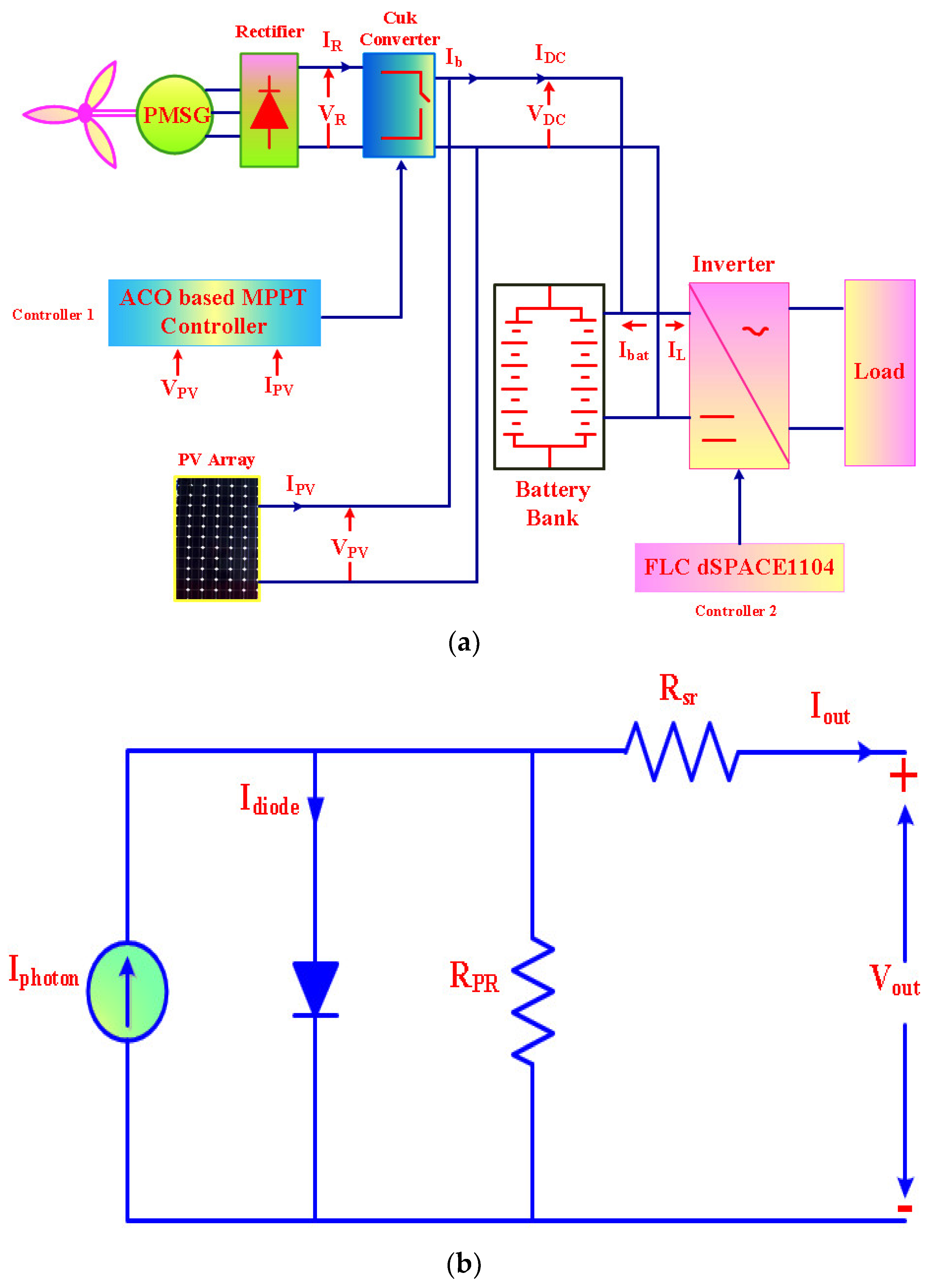
2. Complete Schematic of PV-Wind System

Figure 1a demonstrates standalone hybrid PV-wind-Battery power system comprises of PV modules, PMSG-based WECS, battery, voltage source inverter (VSI) and load. The ACO-based MPPT is employed with single Cuk converter is operating in hybrid power generation for residential application. FLC-dSPACE-based controller is used for inverter voltage regulation to retain inverter voltage regulation and frequency invariable. The employed Cuk converter imparts consistent DC link voltage for charging of battery by application of ACO MPPT.

2.1. PV Modeling

The equivalent mode of PV cell presented in Figure 1b comprises current source, diode and series/parallel resistances. The mathematical equations describing output current ( I o u t ) based on the electrical circuits can be derived with used abbreviations [36] as:
The output current is equated finally with used abbreviations [36] as:
  I o u t = I p h o t o n I R S [ e Q ( V o u t   +   R s r   ×   I o u t ) β K T 1 ] 1 R P R ( V o u t + R s r × I o u t )  

2.2. PMSG Modeling

To describe the operation of PV-Wind system under intermittent operating conditions, Permanent Magnet Synchronous Generator is employed because of zero reactive power consumption. In addition, it does not have need for a gearbox with better power factor and accuracy due to self-execution behavior. The PMSG model has been developed using steady current depicted in Figure 2a. Voltage and current ( V R E & I R E ) obtained from rectification is expressed [1] mathematically with regard to stator voltage/current ( V s t ,   I s t ) .
  V R E = 3 6 π V s t a t o r  
  I R E = π 6 I s t a t o r  

2.3. Mathematical Modeling of Wind Turbine System

The produce power rating of wind turbine based on aerodynamic behavior is evaluated mathematically as [1]:
  P T u r b i n e =   1 2 × C P ( λ t , β P ) ρ a i r π R T 2 V w i n d 3  
The turbine tip speed is correlated with wind velocity and wind turbine rotating velocity Ω T u r b i n e as:
  λ t = Ω T u r b i n e × R T V w i n d
The power coefficient C P ( λ t , β P ) is calculated using mathematical relation as:
  C P ( λ t , β P ) = ( 0.34 0.00166 ) × ( β P 2 ) × sin K × ( 184 ) × 10 5 ( λ t 3 ) ( β P 2 )
And
  K = π ( λ t + 10 1 ) 1434 × 10 2 3 × 10 1 ( β P 2 )  
Mechanical torque τ m e c h a n i c a l developed using wind turbine is related with produced mechanical power as:
  τ m e c h a n i c a l = P m e c h a n i c a l Ω T u r b i n e  
The mechanical relation governing wind turbine system is expressed mathematically as:
( J T u r b i n e + J G e n e r a t o r ) d Ω T u r b i n e d t + f v i s c o u s × Ω T u r b i n e = τ m e c h a n i c a l τ E M  
Mathematical Modeling of PMSG in dq frame is described as:
Energies 12 00167 i001

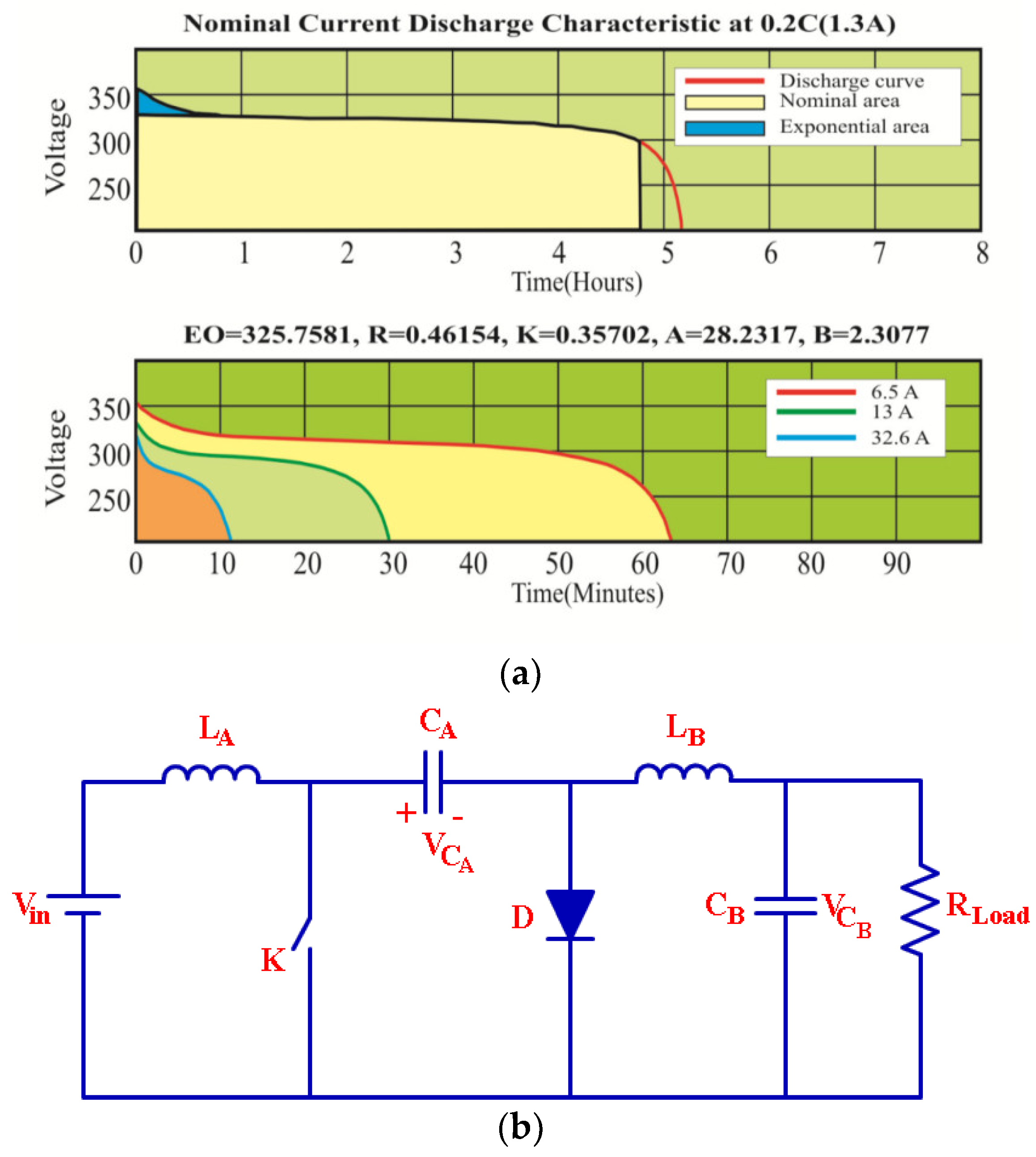
2.4. Electric Circuit-Based Battery Model

In this research work, electric circuit-based battery model is employed which provides better dynamicity for state of charge approximation. It comprises voltage source (ideal) with series internal resistance, which evaluates battery behavior, depicted using Figure 2b. A Battery (Ni-Cd) discharging characteristic is presented with Figure 3a [36].
Final voltage controlled is obtained mathematically as:
  V = E B V P O × Q B a t Q B a t I B a t t e y d t + A e x p × e ( B e x p I B a t t e r y d t )  

2.5. Cuk Converter

The major disadvantages of switched mode power converters have discontinuity of supply current, low dynamic response and higher power device peak current, which made this less acceptable. In contrast with classical switched mode dc-dc converter, Cuk converter comprises less switched power loss, high current behavior with better efficiency, which acts as a power adapter between inverter and renewable sources. The Cuk converter operation presented in Figure 3b is described in two working modes. When power switch gets short-circuited and energy has been released by capacitor. Table 1 presents the specifications used during design of Cuk converter. The mathematical expression-governing mode-I conducting state is described as:
V L A = V i n  
  V L B = V C A V C B  
  I C A = I L B  
  I C B = I L B V C B R L o a d  
In case of power switch gets open circuited, the energy flow takes place with forward biasing diode and input supply is responsible to charge capacitor CA. Described mathematical relations of this mode of operations are:
  V L A = V i n V C A  
  V L B = V C B  
  I C A = I L A  
  I C B = I L B V C B R L o a d  

3. Ant Colony Optimization-Based MPPT

Colorni, Dorigo and Maniezzo invented meta-heuristics-based optimized algorithm to solve difficult non-linear issues. The particular ant to obtain the shortest path optimization generates pheromones. For the searching of foods, the movements of ants take place in different direction followed with generated pheromones. The shortest path should have high pheromones probability as it evaporates in short and methodology is repeated for different iterations to optimize the problems.
In this research work, ACO methodology is implemented by considering VPV and IPV followed by generation of target output (VTarget). Ants have been situated randomly and its movement is noted to achieve VTarget which returns to the colony after this process. Moreover, the VTarget and colony distance is treated as duty ratio of Cuk converter. Let AP variables have targeted to optimize which comprises YP produced randomly solutions (YPAP). Sampling Gaussian Kernel methodology is used for mathematical description as:
  H j ( y ) = L = 1 X ω L h L j ( y ) = L = 1 X ω L 1 σ L j × 2 π × e ( X μ L j ) 2 2 σ L j 2  
Mathematically mean, weight, standard deviations are derived with VP random solutions.
(I)
Mean
  ( μ j ) =   [ μ 1 j , ,   μ L j , ,   μ x j ]  
(II)
Standard deviation
  ( σ L j ) =   ε c o n v j = 1 x | μ i j μ L j | Y P 1  
(III)
Weight
  ω L =   I 2 π × Q L × Y P e ( L 1 ) 2 2 Q L 2 K L 2  
(IV)
Probability of Gaussian function selection
  P L = ω L R = 1 x ω R  
The proposed sample Process is repeated for optimization of parameters. Let ZP newly solution are produced and has addition with YP initially obtained solution. Total ZP + YP solutions have been obtained in which YP best are replicated and overall methodology is recapitulated for several iterations. Figure 4 presents the flowchart of ACO-based MPPT which describes the step by step process.
Step I:
Parameters (ZP, YP, QP, ξconv) have been initialized.
Step II:
The voltage, current and power associated with every ant can be calculated and process has been repeated until YP ant.
Step III:
Gaussian function has been evaluated to get ZP new solutions.
Step IV:
ZP + YP has been ranked to store YP best solution.
Step V:
All 4 steps have been repeated till maximum iterations.
Table 2 shows ACO parameters used during practical verification. This methodology is stimulated by foraging nature of ants, which are treated as blind living things, and conversion among them takes place-using pheromone alchemical. It comprises positive feedback affection, which provides better-optimized solutions.

4. Inverter Control, MPPT and Inverter Controller Action with Single Cuk Converter and Experimental Set Up

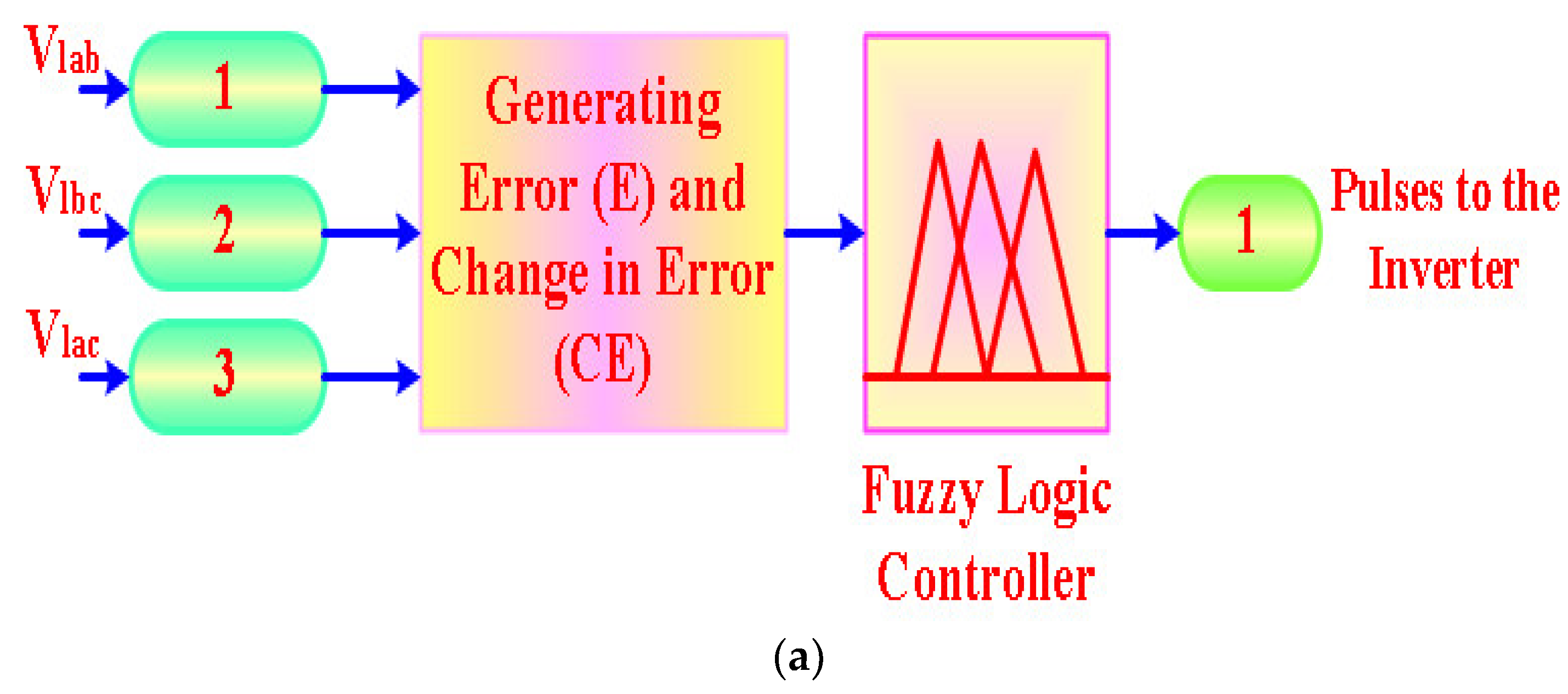
4.1. FLC-Based Inverter Control

The inverter depicted in Figure 5a is controlled with Fuzzy Logic Control (FLC)-based intelligent methodology, which provides the smooth maintenance of load voltage and frequency. Irrespective of wind velocity, loading conditions and level of sun insolation inverter regulates voltage and frequency instant. Figure 5b depicts the FLC regulated inverter controller. For maintenance of voltage output (Vout) and frequency, a phase locked loop (PLL) presented in Figure 5b associated with synchronized frame of reference is employed. The FLC inverter control regulation provides better efficiency, stable operation and less frequency, disturbances with respect to PI-based inverter regulation [21]. Figure 6a–d demonstrate the PWM pulse generation using FLC inverter strategy and membership functions used during implementation, respectively.

4.2. MPPT and Inverter Controller Action with Single Cuk Converter

CASE I: The two controllers operations are decided based on the presence of PV/Wind renewable sources. In case of generation of power from PV as well as wind sources, the ACO-based MPPT (controller 1) produces duty ratio for Cuk power converter and FLC inverter control (controller 2) provides power generation from PV and wind renewable sources.
CASE II: In case of power generation from only wind renewable sources (Not PV), the duty ratio of the Cuk converter is generated to make DC link voltage fixed and controller 1 works in voltage control mode. In addition to this controller 2 tries to obtain optimal wind power by generating current signal.
CASE III: When PMSG is not in operation and only PV sources are generating power, Cuk converter has no input and there is no pulse generation using controller 1. Controller 2 produces current command signal to obtain optimal PV power generation from PV modules.

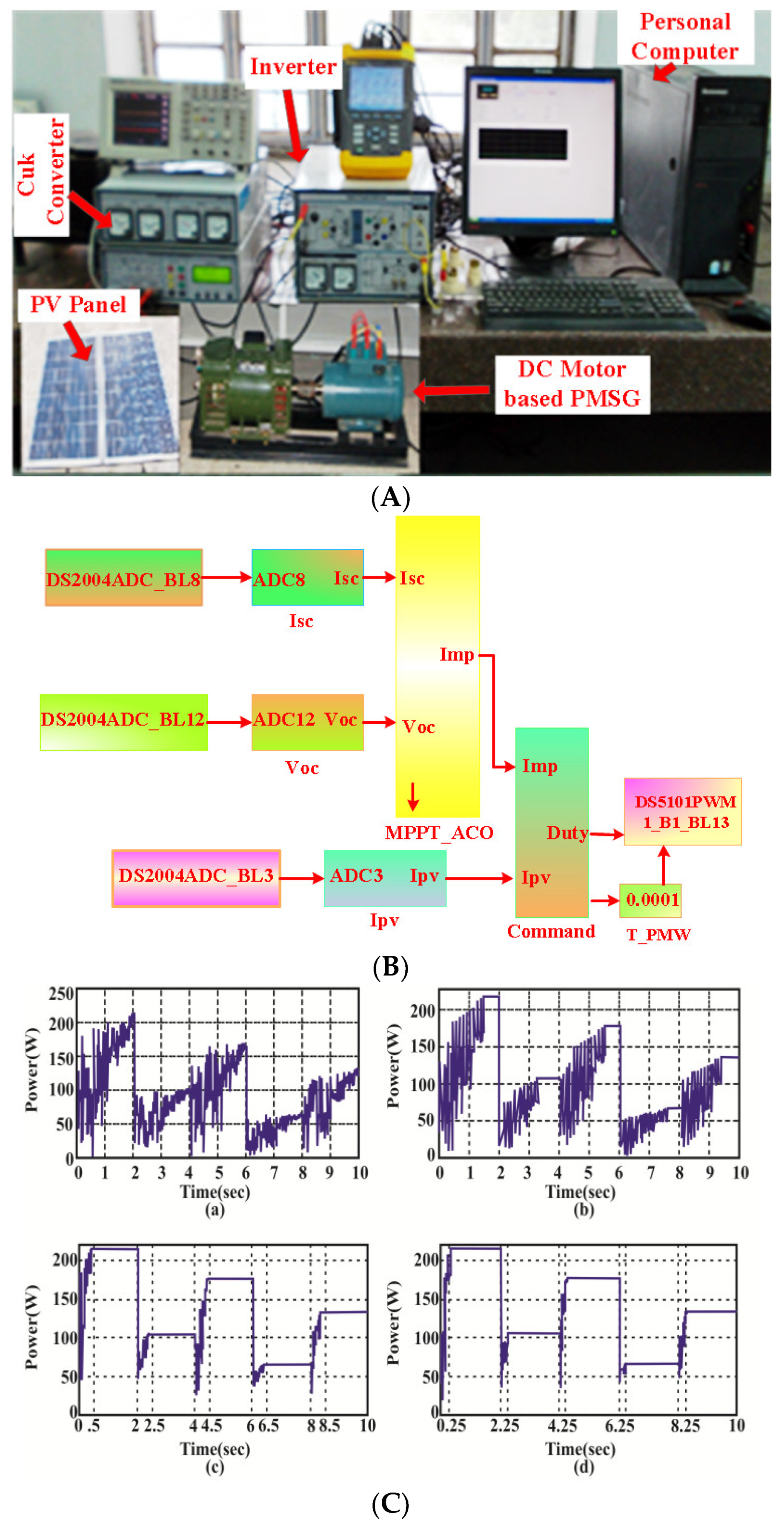
4.3. Experimental Set Up

Figure 7A depicts the practical set up developed for proposed hybrid (PV-Wind) system controlled through dSPACE, which comprises PV module, wind emulator, Cuk converter, and electric circuit-based battery model.
With application of ACO model based MPPT the sensed (Voltage/Current) is transformed to digital pulses by analog to digital converter and controller 1 and controller 2 generated signals are collected from control desk I/O of dSPACE which is processed through insolation interface. LA50-P (current transducer) and LV20-P (voltage transducer) are employed during experimentation, respectively. The ACO based MPPT is modeled in Figure 7B using MATLAB which generates PWM signal for Cuk converter linked through dSPACE hardware based CT60 AM IGBT, SKHI22 AR gating driver, power supplication using programmed DCMAGNA (programmable DC power supply) and PMSG wind emulators are employed during practical investigation.

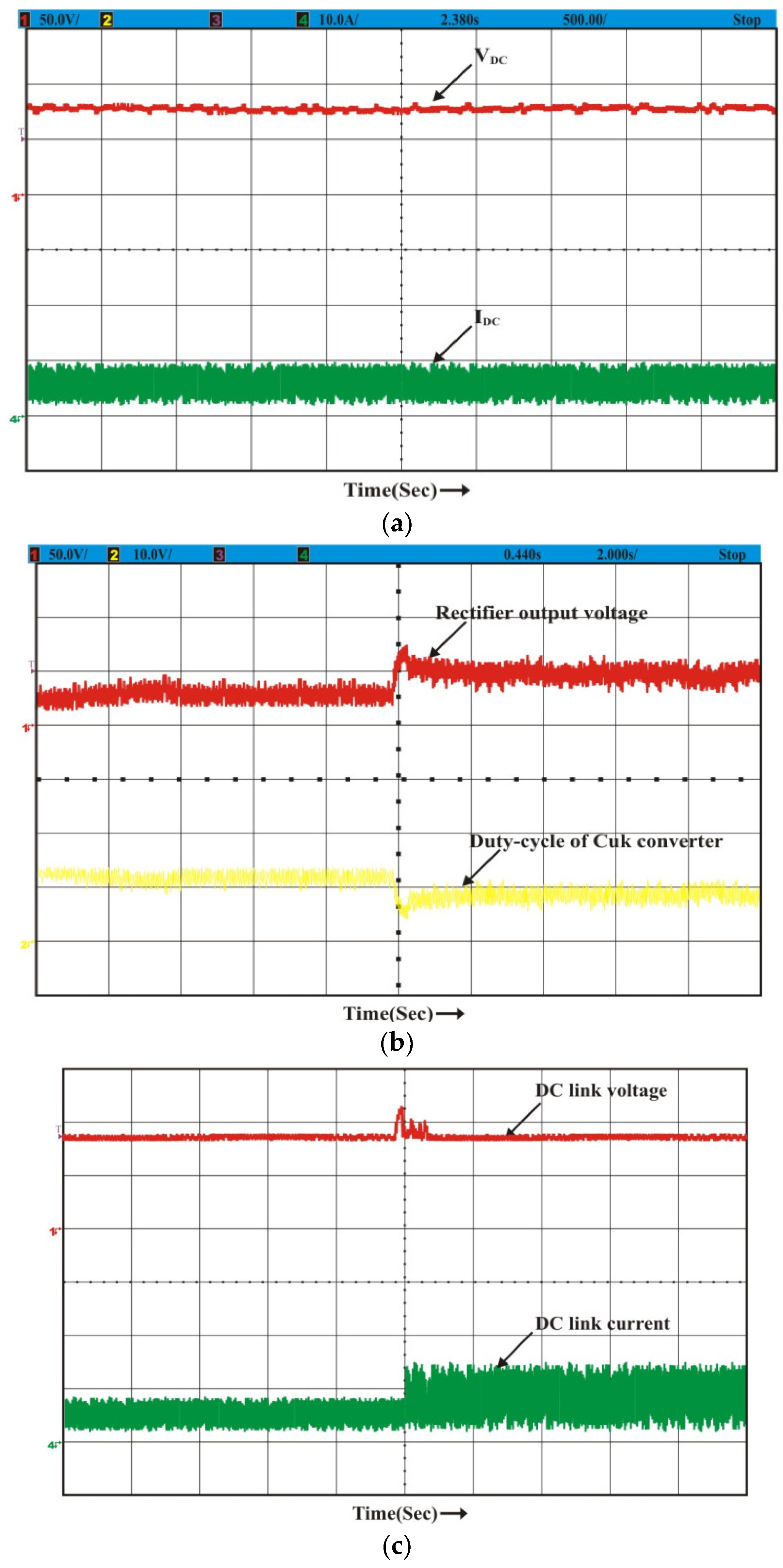
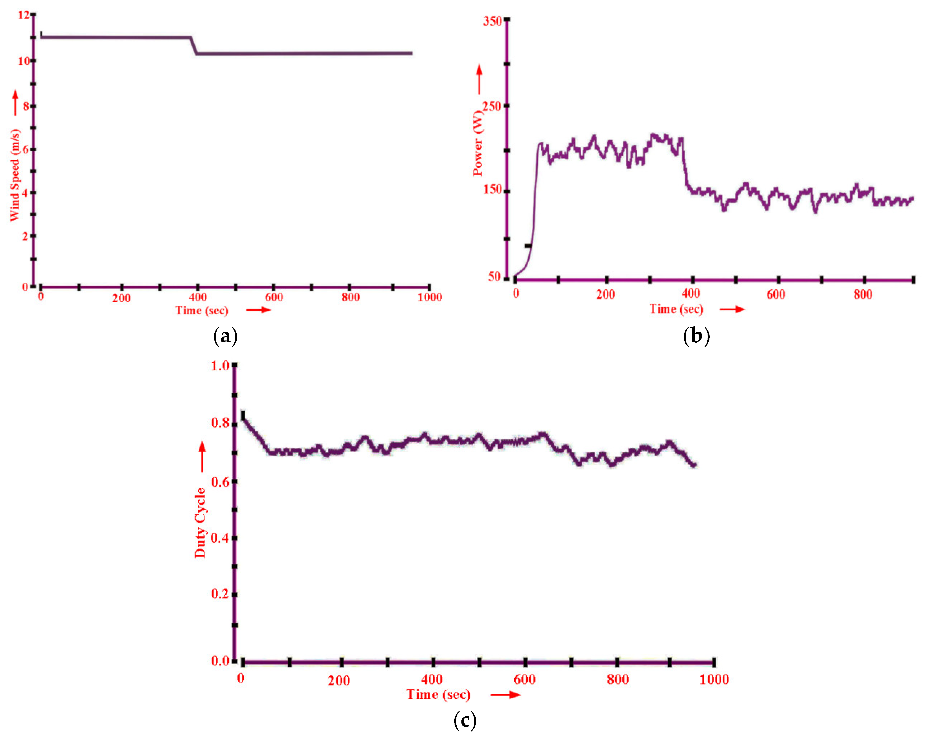
5. Experimental Responses

Practical justification is done by comparing power tracking behavior of ACO algorithm vs. PSO, FA and ABC techniques using Figure 7C. The average period required to achieve MPP is presented with comparison using Table 3. The ACO based MPPT method takes lesser time compared to other algorithms mentioned. Moreover, the duty ratio performance with ACO MPPT is better compared to other techniques employed in Figure 7D. Figure 8a portrays the starting operation before GMP achievements in which PV module voltage level tries to reach preset level of voltage. The steady state behavior of the designed PV system is also examined and is justified with matched PV characteristics depicted by Figure 8b. By means of proposed intelligent ACO, the inverter current becomes synchronized in Figure 8c. The dynamic performance of ACO based PV power system has been justified with variations in fluctuating sun insolation and can be depicted in Figure 8d. Figure 9a demonstrates the responses obtained from hybrid PV-wind controlled ACO, which clearly interprets that MPPT operation is achieved independently without influencing one another.
The intermittent behavior of PV-wind system with proposed methodology is accurately tested experimentally using proposed algorithm. Abruptly, the PV-wind power system has been turned ON/OFF and output responses are noted under these operating situations. Figure 9b presents the responses of hybrid system when wind turbine gets turns ON/OFF abruptly. It is clearly visualized that the PV system works independently and provides output power without influencing one another. The PV/Wind renewable sources are transferring power one of two concurrently or particularly. Complementary, the performance of hybrid PV-Wind system is evaluated when PV system is turned ON/OFF which does not influence the wind turbine operation when abrupt changes occurs in PV system, which is depicted in Figure 9c. The transient performance of the hybrid control system has been evaluated by keeping wind condition constant and sun insolation variable. The corresponding change in VPV, IPV and Ibattery is noted under fluctuating sun irradiance. Battery gets charge and discharge depending on increasing/decreasing nature of solar insolation, which maintains the terminal voltage fixed and validates the effective design of proposed algorithms regulation. The power output generations from hybrid (PV and Wind) energy sources are compared using Figure 10a,b, respectively using PI and FLC regulated inverter control. In case of PI based inverter controller, voltage output (Vout) is found unstable and has more frequency perturbation in contrast to FLC based inverter control illustrated using Figure 10 responses.
Under steady state operating conditions, the DC link voltage/current is noted under variable solar insolation 400 W/m2 and PMSG turbine velocity 5 × 10⁻¹ p.u. is illustrated using Figure 11a. The dynamic behavior of proposed hybrid power system is tested under operating conditions (Fixed Sun insolation 700 W/m2 and increment in PMSG shaft velocity 0.5 to 0.75 p.u.). Therefore, consequent variation in VRectifier and Cuk converter duty ratio is reported to keep DC link voltage fixed explained using Figure 11b. Figure 11c illustrates the corresponding rectifier waveforms and DC link voltage/current obtained during experimentation. The performance of ACO based MPPT for wind energy conversion system has been realized through experimental responses obtained during varying wind velocity depicted in Figure 12a. The practical responses presented in Figure 12b,c extracted wind turbine power and Cuk converter duty ratio, respectively justify the optimal tracking ability and operation in maximum power point region of ACO based MPPT for wind energy conversion system. The reliable operation of PV-Wind system with ACO MPPT control has been practically substantiated using dSPACE interface. Table 4 demonstrates the used PV and Wind turbine specifications for practical justification.

6. Conclusions

The ACO based optimized methodology provides optimal power extraction from solar and wind energy sources for residential applications, which contained high convergence velocity, better-searched performance and simpler implementation as major advantage. The completed hybrid solar wind driven PMSG power system is modeled through MATLAB and provides hardware interface (dSPACE) for validation and confirmation of high power generation. Under low wind velocity, the hybrid system has low battery consumption, which demonstrates the improved controller performance. Inverter regulated with FLC-dSPACE control has power efficiency equated with classical PI-controller. The hybrid integration of solar and wind energy system have been realized experimentally under various conditions to develop novel hybrid power system followed by Cuk converter. ACO algorithms developed using m-file have complex coding interfaced to a dSPACE hardware board. The performance of ACO based MPPT has been evaluated versus PSO, FA and ABC algorithms. Experimental results reveal that the ACO based MPPT provides seven times faster convergence compared to the PSO algorithm for achievement of MPP and tracking efficiency. The limitations of this adopted hybrid control system are a requirement of ideal layout for installation of PV modules and wind turbine with adequate wind and solar insolation. The installation cost is another limitation of this hybrid PV-Wind system. Included work can be extended to learning framework with Internet of Things-based intelligent algorithms for PV-Wind hybrid system to achieve utmost power tracking efficiency.

Author Contributions

All authors contributed equally for the decimation of the research article in current form.

Funding

This research received no external funding.

Conflicts of Interest

The authors declare no conflict of interest.

Nomenclature

C P ( λ t , β P ) Power Coefficient of wind turbine
ρ a i r Density of air
R T Blade (Wind turbine) radius
ν w i n d Wind velocity
λ t Tip speed ratio
β P Pitch blade angle
f v i s c o u s Viscous force
τ E M Developed electromagnetic torque
R s t a t o r Stator resistance
L d a x i s , L q a x i s Inductances of Stator winding
I s d a x i s , I s q a x i s Stator winding current
P M Flux generated by permanent magnet
PNo. of Poles
E B Battery fixed voltage
V P O Polarized voltage
Q B a t Capacity of battery
I B a t t e y Battery current
A e x p Amplitude of exponential zone
B e x p Inverse time constant exponential zone
Hj(y)jth Gaussian kernel
h L j   ( y ) jth Gaussian function
σ L j Standard deviation
μ L j Mean function
ɛconvRate of convergence
QLBest rank solution
APParameters to be optimized
YPInitial random solutions

References

  1. Singaravel, M.M.R.; Daniel, S.A. MPPT with Single DC-DC Converter and Inverter for Grid Connected Hybrid Wind-Driven PMSG-PV System. IEEE Trans. Ind. Electron. 2015, 62, 4849–4857. [Google Scholar] [CrossRef]
  2. Chen, Y.M.; Liu, Y.C.; Hung, S.C.; Cheng, C.S. Multi-Input Inverter for Grid-Connected Hybrid PV/Wind Power System. IEEE Trans. Ind. Electron. 2007, 22, 1070–1077. [Google Scholar] [CrossRef]
  3. Wandhare, R.G.; Agarwal, V. Novel Integration of PV-Wind Energy System with Enhanced Efficiency. IEEE Trans. Power Electron. 2015, 30, 3638–3649. [Google Scholar] [CrossRef]
  4. Geng, H.; Liu, L.; Li, R. Synchronization and Reactive Current Support of PMSG based Wind Farm during Severe Grid Fault. IEEE Trans. Sustain. Energy 2018. [Google Scholar] [CrossRef]
  5. Das, S.; Subudhi, B. A H Robust Active and Reactive Power Control Scheme for a PMSG based Wind Energy Conversion System. IEEE Trans. Energy Convers. 2018, 33, 980–990. [Google Scholar] [CrossRef]
  6. Ahmed, J.; Salam, Z. An Enhanced Adaptive P&O MPPT for Fast and Efficient Tracking under Varying Environmental Conditions. IEEE Trans. Sustain. Energy 2018, 9, 1487–1496. [Google Scholar]
  7. Xiao, X.; Huang, X.; Kang, Q. A Hill Climbing Method-Based Maximum Power Point-Tracking Strategy for Direct-Drive Wave Energy Converters. IEEE Trans. Ind. Electron. 2016, 63, 257–267. [Google Scholar] [CrossRef]
  8. Kumar, N.; Hussain, I.; Singh, B.; Panigrahi, B.K. Self-Adaptive Incremental Conductance Algorithm for Swift and Ripple Free Maximum Power Harvesting from PV Array. IEEE Trans. Ind. Inform. 2018, 14, 2031–2041. [Google Scholar] [CrossRef]
  9. Khateb, A.E.; Rahim, N.A.; Selvaraj, J.; Uddin, M.N. Fuzzy Logic Controller Based SEPIC Converter for Maximum Power Point Tracking. IEEE Trans. Ind. Appl. 2014, 50, 2349–2358. [Google Scholar] [CrossRef]
  10. Lin, W.M.; Hong, C.M.; Chen, CH. Neural-Network-Based MPPT Control of a Stand-Alone Hybrid Power Generation System. IEEE Trans. Power Electron. 2011, 26, 3571–3581. [Google Scholar] [CrossRef]
  11. Priyadarshi, N.; Anand, A.; Sharma, A.K.; Azam, F.; Singh, V.K.; Sinha, R.K. An Experimental Implementation and Testing of GA based Maximum Power Point Tracking for PV System under Varying Ambient Conditions Using dSPACE DS 1104 Controller. Int. J. Renew. Energy Res. 2017, 7, 255–265. [Google Scholar]
  12. Koad, R.B.A.; Zobaand, A.F.; Shahat, A.E. A Novel MPPT Algorithm Based on Particle Swarm Optimisation for Photovoltaic Systems. IEEE Trans. Sustain. Energy 2017, 8, 468–476. [Google Scholar] [CrossRef]
  13. Sundareswaran, K.; Peddapati, S.; Palani, S. MPPT of PV Systems under Partial Shaded Conditions through a Colony of Flashing Fireflies. IEEE Trans. Energy Convers. 2014, 29, 463–472. [Google Scholar]
  14. Sundareswaran, K.; Sankar, P.; Nayak, P.S.R.; Simon, S.P.; Palani, S. Enhanced Energy Output from a PV System Under Partial Shaded Conditions Through Artificial Bee Colony. IEEE Trans. Sustain. Energy 2015, 6, 198–209. [Google Scholar] [CrossRef]
  15. Ram, J.P.; Rajasekar, N. A novel Flower Pollination based Global Maximum Power Point method for Solar Maximum Power Point Tracking. IEEE Trans. Power Electron. 2017, 32, 8486–8499. [Google Scholar]
  16. Mohanty, S.; Subudhi, B.; Ray, P.K. A Grey Wolf Assisted Perturb & Observe MPPT Algorithm for a PV System. IEEE Trans. Energy Convers. 2017, 32, 340–347. [Google Scholar]
  17. Belhachat, F.; Larbes, C. Global maximum power point tracking based on ANFIS approach for PV array configurations under partial shading conditions. Renew. Sustain. Energy Rev. 2017, 77, 875–889. [Google Scholar] [CrossRef]
  18. Sundareswaran, K.; Kumar, V.V.; Sankar, P.; Simon, S.P.; Nayak, P.S.R.; Palani, S. Development of an improved P&O algorithm assisted through a colony of foraging ants for MPPT in PV system. IEEE Trans. Ind. Inform. 2016, 12, 187–200. [Google Scholar]
  19. Emerson, N.; Srinivasan, S. Integrating Hybrid Power Source into Islanded Micro grid Using Ant Colony Optimization. In Proceedings of the International Conference on Advanced Computing and Communication Systems (ICACCS-2015), Coimbatore, India, 5–7 January 2015; pp. 1–4. [Google Scholar]
  20. Banaei, M.R.; Sani, S.G. Analysis and implementation of a new SEPIC-based single switch buck-boost dc-dc converter with continuous input current. IEEE Trans. Power Electron. 2018. [Google Scholar] [CrossRef]
  21. Pachauri, R.K.; Chauhan, Y.K. Modeling and Simulation Analysis of PV Fed Cuk, Sepie, Zeta and Luo DC-DC Converter. In Proceedings of the International Conference on Power Electronics Intelligent Control and Energy Systems (ICPEICES-2016), Delhi, India, 4–6 January 2016; pp. 1–6. [Google Scholar]
  22. Farhat, M.; Barambones, O.; Sbita, L. Efficiency boosting for PV systems using new MPPT method. In Proceedings of the of 23rd Mediterranean Conference on Control and Automation (MED), Torremolinos, Spain, 16–19 June 2015; pp. 777–782. [Google Scholar]
  23. Shiau, J.-K.; Wei, Y.-C.; Lee, M.-Y. Fuzzy Controller for a Voltage-Regulated Solar-Powered MPPT System for Hybrid Power System Applications. Energies 2015, 8, 3292–3312. [Google Scholar] [CrossRef] [Green Version]
  24. Robles Algarín, C.; Taborda Giraldo, J.; Rodríguez Álvarez, O. Fuzzy Logic Based MPPT Controller for a PV System. Energies 2017, 10, 2036. [Google Scholar] [CrossRef]
  25. Hong, C.-M.; Ou, T.-C.; Lu, K.H. Development of intelligent MPPT (maximum power point tracking) control for a grid-connected hybrid power generation system. Appl. Energy 2013, 50, 270–279. [Google Scholar] [CrossRef]
  26. Lin, W.-M.; Hong, C.-M.; Ou, T.-C.; Chiu, T.-M. Hybrid intelligent control of PMSG wind generation system using pitch angle control with RBFN. Energy Convers. Manag. 2011, 52, 1244–1251. [Google Scholar] [CrossRef]
  27. Ou, T.-C.; Lin, W.-M.; Huang, C.-H. A Multi-Input Power Converter for Hybrid Renewable Energy Generation System. In Proceedings of the IEEE PES/IAS Conference on Sustainable Alternative Energy (SAE), Valencia, Spain, 28–30 September 2009; pp. 1–7. [Google Scholar]
  28. Ou, T.-C. A novel unsymmetrical faults analysis for microgrid distribution systems. Electr. Power Energy Syst. 2012, 43, 1017–1024. [Google Scholar] [CrossRef]
  29. Ou, T.-C.; Hong, C.-M. Dynamic operation and control of microgrid hybrid power systems. Appl. Energy 2014, 66, 314–323. [Google Scholar] [CrossRef]
  30. Ou, T.-C. Ground fault current analysis with a direct building algorithm for microgrid distribution. Electr. Power Energy Syst. 2013, 53, 867–875. [Google Scholar] [CrossRef]
  31. Ou, T.-C.; Lu, K.-H.; Huang, C.-J. Improvement of Transient Stability in a Hybrid Power Multi-System Using a Designed NIDC (Novel Intelligent Damping Controller). Energies 2017, 10, 488. [Google Scholar] [CrossRef]
  32. Mellit, A.; Rezzouk, H.; Messai, A.; Medjahed, B. FPGA-based real time implementation of MPPT-controller for photovoltaic systems. Renew. Energy 2011, 36, 1652–1661. [Google Scholar] [CrossRef]
  33. Liu, C.-L.; Chen, J.-H.; Liu, Y.-H.; Yang, Z.-Z. An Asymmetrical Fuzzy-Logic-Control-Based MPPT Algorithm for Photovoltaic Systems. Energies 2014, 7, 2177–2193. [Google Scholar] [CrossRef] [Green Version]
  34. Santra, S.B.; Behera, S.K.; Panigrahi, C.K. Stability Analysis and Control of hybrid Solarand Wind System through NI c-RIO. In Proceedings of the 7th India International Conference on Power Electronics (IICPE), Patiala, India, 17–19 November 2016; pp. 1–6. [Google Scholar]
  35. Broujeni, S.T.; Fathi, S.H.; Kumle, A.N. Effects of Fault Condition on the Performance of Hybrid PV/Wind Power Systems. In Proceedings of the 11th International Conference on Electrical Engineering/Electronics, Computer, Telecommunications and Information Technology (ECTI-CON), Nakhon Ratchasima, Thailand, 14–17 May 2014; pp. 1–6. [Google Scholar]
  36. Saidi, A.; Chellali, B. Simulation and Control of Solar Wind Hybrid Renewable Power System. In Proceedings of the 6th International Conference on Systems and Control, Batna, Algeria, 7–9 May 2017; pp. 51–56. [Google Scholar]
Figure 1. (a) Standalone hybrid PV-wind-Battery power system; (b) PV cell equivalent model.
Energies 12 00167 g001
Figure 2. (a) PMSG model has been developed using steady current; (b) Electric circuit based battery model.
Energies 12 00167 g002
Figure 3. (a) Battery (Ni-cd) discharging behavior; (b) Cuk converter.
Energies 12 00167 g003
Figure 4. Flowchart of ACO-based MPPT.
Energies 12 00167 g004
Figure 5. (a) Inverter control; (b) FLC regulated inverter controller.
Energies 12 00167 g005
Figure 6. (a) FLC pulse generation; (b) Membership functions Error; (c) Membership functions change in error; (d) Membership functions duty ratio.
Energies 12 00167 g006aEnergies 12 00167 g006b
Figure 7. (A) Practical set up developed for proposed hybrid (PV-Wind) system; (B) ACO MPPT implementation using dSPACE; (C) Power tracking (a) PSO, (b) FA, (c) ABC, (d) ACO; (D) Duty ratio (a) PSO, (b) ABC, (c) ACO.
Energies 12 00167 g007aEnergies 12 00167 g007b
Figure 8. (a) Starting operation PV MPPT; (b) Steady state behavior of the designed PV system; (c) Inverter current and voltage; (d) ACO based PV power system with variations in fluctuating sun insolation.
Energies 12 00167 g008aEnergies 12 00167 g008b
Figure 9. (a) PV-wind MPPT operation without influencing one another; (b) Responses of hybrid system when wind turbine gets turns ON/OFF abruptly; (c) Performance of hybrid PV-Wind system is evaluated when PV system gets turned ON/OFF.
Energies 12 00167 g009aEnergies 12 00167 g009b
Figure 10. Transient performance of the hybrid control system (a) FLC inverter control; (b) PI-control.
Energies 12 00167 g010
Figure 11. (a) Steady state operating conditions, the DC link voltage/current; (b) Dynamic behavior of proposed hybrid power system variation in VRectifier and Cuk converter duty ratio; (c) Corresponding rectifier waveforms and DC link voltage/current.
Energies 12 00167 g011
Figure 12. Practical ACO based MPPT for wind energy conversion (a) varying wind velocity; (b) extracted wind power and (c) Cuk converter duty ratio.
Energies 12 00167 g012
Table 1. Cuk converter parameters.
S.N.ParametersValues
1.Inductor (LA = LB)0.5 mH
2.Capacitor (CA = CB)1.5 µF
3.Frequency of Switching10 KHz
4.Diode500 V/7 A
5.MOSFET (Power Switch K)600 V/12 A
Table 2. ACO parameters used during experiment.
S.N.ParametersValues
1.Total iterations250
2.Size of Population10
3.Produced random solution8
4.Rate of convergence0.35
5.Best Rank solution (QL)0.85
Table 3. Performance MPPT comparison.
S.N.TechniquesTracking Time (Avg.)
1.PSO5.1 s
2.FA2.75 s
3.ABC0.75 s
4.ACO0.38 s
Table 4. PV and Wind turbine specifications.
S.N.ParametersValues
1.PV rated power200 W
2.Wind generation (Rated)200 W
3.Stator and Rotor resistance4.3 Ω, 3.8 Ω
4.Number of Poles4

