Design, Analysis and Test of a Hyperbolic Magnetic Field Voice Coil Actuator for Magnetic Levitation Fine Positioning Stage


1
School of Electrical Engineering and Automation, Harbin Institute of Technology, 150001 Harbin, China
2
College of Electrical and Electronic Engineering, Harbin University of Science and Technology, 150001 Harbin, China
*
Author to whom correspondence should be addressed.
Energies 2019, 12(10), 1830; https://doi.org/10.3390/en12101830
Submission received: 13 April 2019
/
Revised: 29 April 2019
/
Accepted: 10 May 2019
/
Published: 14 May 2019
(This article belongs to the Special Issue Electrical Machine Design)
Abstract
:The multi-degree-of-freedom high-precision positioning system (MHPS) is one of the key technologies in many advanced industrial applications. In this paper, a novel hyperbolic magnetic field voice coil actuator using a rhombus magnet array (HMF-VCA) for MHPS is proposed. Benefiting from the especially designed rhombus magnet array, the proposed HMF-VCA has the advantage of excellent force uniformity, which makes it suitable for multi-degree-of-freedom high-precision positioning applications. First, the basic structure and operation principles of the HMF-VCA are presented. Second, the six-degree-of-freedom force and torque characteristic of the HMF-VCA is studied by three-dimensional finite element analysis (3-D FEA). Third, the influence of structural parameters on force density and force uniformity is investigated, which is conducive to the design and optimization of the HMF-VCA. Finally, a prototype is constructed, and the comparison between the HMF-VCA and conventional VCAs proves the advantage of the proposed topology.
1. Introduction
The multi-degree-of-freedom high-precision positioning system (MHPS) is one of the key technologies in many advanced industrial applications, such as semiconductor lithography, scanning tunneling microscope, chemistry and biomedical science [1,2,3,4,5,6,7]. Generally, the MHPS can be realized by three solutions: stacking linear actuators, planar actuators [1,8,9], and combining coarse positioning stage (CPS) and fine positioning stage (FPS) [10,11,12]. Benefiting from the two-stage structure, the third solution becomes a widely adopted scheme, which can simultaneously satisfy the requirements of long stroke and high accuracy. Among various FPSs, the magnetic levitation fine positioning stage (MLFPS) is considered to be the state of the art because of its feature of no mechanical contact. In the MLFPS, a stage that integrates multiple actuators and sensors is often adopted, in which the actuator is an electromagnet [13,14,15], or a voice coil actuator (VCA) [12,16,17]. As a key component of the MLFPS, the performance of actuators strongly determines the MLFPS’s positioning ability. Compared with single-degree-of-freedom applications, the MLFPS has special technical requirements for the actuators because of its multi-degree-of-freedom motion. When an actuator works in multi-degree-of-freedom, not only will its output force in the driving direction be influenced by the motion in the other directions, but it will also produce parasitic force and torque, which will reduce the MLFPS’s performance and increase the control system’s complexity [18]. Therefore, the actuators used in the MLFPS should be designed to be able to output a force which is independent from the six-degree-of-freedom motion, and in this paper the ability is named as force uniformity. In this paper, we put forward a novel hyperbolic magnetic field voice coil actuator using a rhombus magnet array (HMF-VCA) to achieve this goal, and focus on the analysis of its complex six-degree-of-freedom force and torque characteristics.
2. Basic Structure and Operating Principle
2.1. Basic Structure
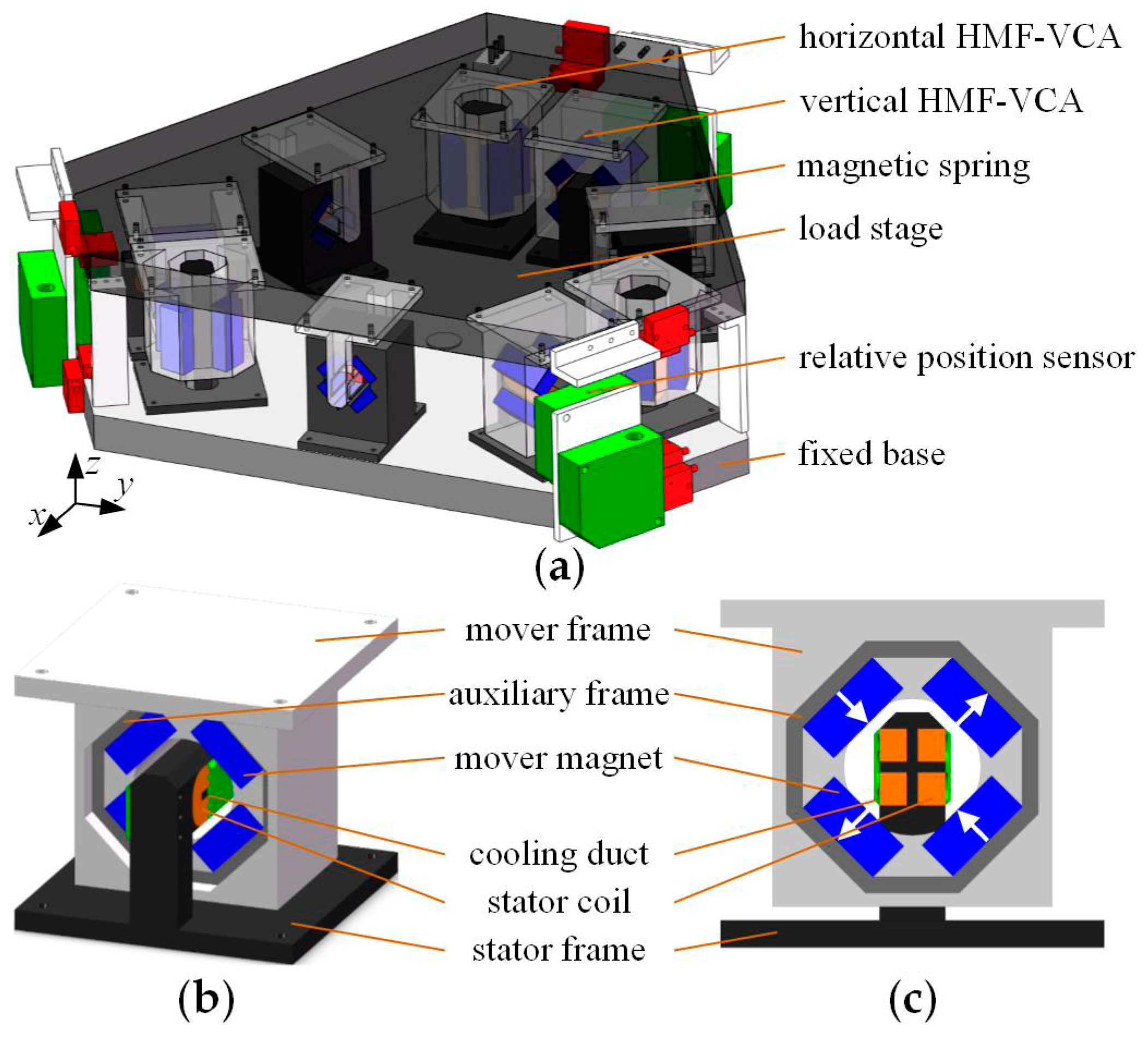
Figure 1 shows the structure of the proposed HMF-VCA and MLFPS. The HMF-VCA consists of two components, i.e., stator and mover. The stator consists of two rectangular stator coils with cooling duct, and a non-ferromagnetic stator frame. The mover consists of a rhombus magnet array, a non-ferromagnetic auxiliary frame, and a non-ferromagnetic mover frame. The rhombus magnet array consists of four cubic mover magnets which are arranged on the four edges of a rhombus, and the magnetization is shown as arrows. The MLFPS is made up of a load stage, a fixed base, three vertical HMF-VCAs, three horizontal HMF-VCAs, three magnetic springs, six relative position sensors, and the corresponding drive and control system. To reduce heat generation and mechanical coupling on the moving part, most devices with cables are installed on a fixed base. It should be noted that the liquid cooling system is optional, depending on the practical application.
2.2. Operating Principles
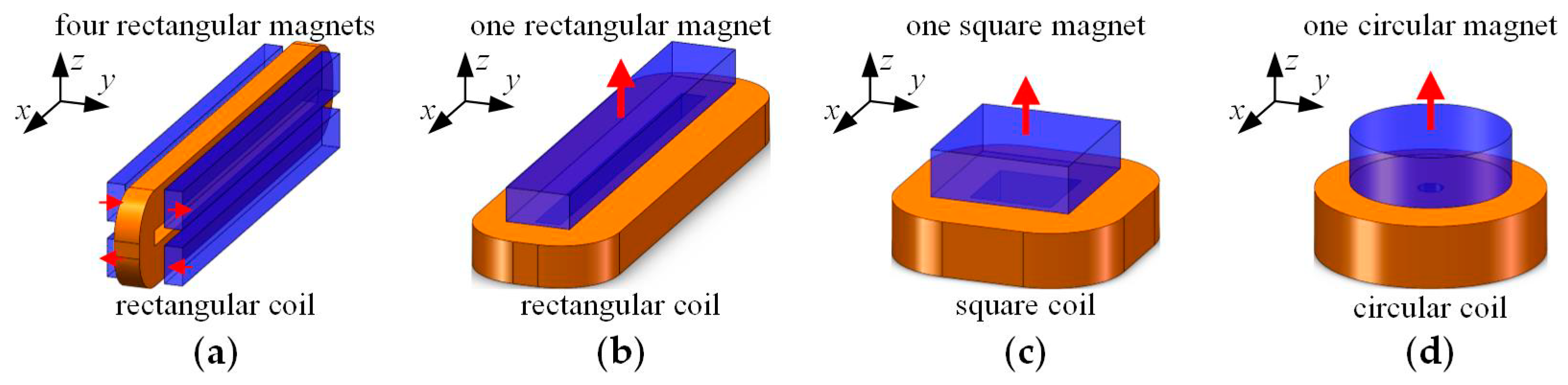
Similar to conventional VCAs, the HMF-VCA also works based on the Lorenz force law. The difference between the HMF-VCA and conventional VCAs is their different magnetic field distribution. Figure 2 shows the structure of four types of conventional VCAs which are used in high-precision applications, i.e., VCA with four rectangular magnets (FR-VCA), and VCA with one rectangular or square or circular magnet (OR/OS/OC-VCA) [18], and Figure 3 shows the magnetic field distribution and output force of these VCAs. The magnetic field distribution is calculated with Ansys Maxwell 2D. The materials of permanent magnets and coils are set to be NdFeB35 (Hc = 890 kA/m, Br = 1.23 T) and copper, respectively. The current density in the coils is set to be 5 A/mm2. The parameters in Figure 3 are set as follows: in Figure 3a, wm1 = 5.4 mm, tm1 = 2.539 mm, wc1 = 5.7 mm, tc1 = 3.6 mm, ws1 = 2.5 mm, ws2 = 2.2 mm, ts1 = 1 mm, model depth 64.64 mm; in Figure 3b, wm2 = 9.5 mm, tm2 = 5.12 mm, wc2 = 8.9 mm, tc2 = 6.3 mm, ws3 = 3.7 mm, ts2 = 1 mm, model depth 59.3 mm; in Figure 3c, wm = 18 mm, tm = 8 mm, wc = 6 mm, tc = 5 mm, ws = 2 mm, ts = 2 mm, yq = 8 mm, zq = 8 mm, model depth 36.86 mm. The stroke is set to be ±0.5 mm × ±0.5 mm.
As shown in Figure 3a,d, the magnetic field in the coil region of FR-VCA is relatively strong, which is beneficial to obtainig higher force density; however, the output force Fz will inevitably change when the coil moves along the z axis, because the magnetic field component By is approximately sinusoidal, as shown in Figure 3g.
From Figure 3b,e, it can be seen that the magnetic field component By in the coil region of OR-VCA is rather inhomogeneous; although it is occasionally used because of its simple structure, it has the worst force characteristic, as shown in Figure 3h, and this conclusion is also applicable to OS-VCA and OC-VCA.
To obtain better force uniformity, the rhombus magnet array is designed and applied in the HMF-VCA. As shown in Figure 3c, the magnetic field in the HMF-VCA looks like a cluster of hyperbolas. With this hyperbolas-like magnetic field, the magnetic field component By is proportional to the value of z, as shown in Figure 3f. In this case, when the mover moves relative to the stator, the increase (decrease) of the force acting on the upper part of the stator coils is equal to the decrease (increase) of the force acting on the lower part of the stator coils, thus the output force will remain constant, as shown in Figure 3i, and the HMF-VCA can achieve excellent force uniformity.
In addition, the MLFPS’s load stage will be levitated and positioned with at least six HMF-VCAs, but this content is not discussed in this paper. We focus on the analysis of the HMF-VCA’s six-degree-of-freedom force and torque characteristics.
3. Characteristics Analysis and Optimization
As discussed in Section 1, the mover of the HMF-VCA will move in six-degrees-of-freedom relative to the stator, i.e., it will translate along the x, y, z axis, and rotate around the x, y, z axis, as shown in Figure 4a. Besides the six-degree-of-freedom motion, the levitated mover is also subjected to six-degree-of-freedom force and torque, i.e., the force Fx, Fy, Fz along the x, y, z axis and the torque Tx, Ty, Tz around the x, y, z axis, as shown in Figure 4b.
Considering the influence of six-degree-of-freedom motion on the six-degree-of-freedom force and torque, a three-dimensional finite element analysis (3-D FEA) is employed to study the HMF-VCA’s complex force and torque characteristic. The analytical method which has the fastest computing speed is another choice to study the characteristic of voice coil actuators, and the related modeling study can be found in [19]. However, there is a modeling error when the analytical method is used to calculate a permanent magnet the permeability of which is not 1 [20]. Therefore, the finite element method is chosen in this paper. The HMF-VCA’s structural parameters are listed in Figure 5 and Table 1. The materials of permanent magnets and coils are set to be NdFeB35 (Hc = 890 kA/m, Br = 1.23T) and copper, respectively. The current density in the coils is set to be 5 A/mm2. As the two-dimensional magnetic field distribution of the HMF-VCA is given in Figure 3c, it is not repeated here.
According to the analysis of Figure 3c,f, the HMF-VCA’s output force will remain constant in its stroke, and the 3-D FEA results shown in Figure 6, Figure 7, Figure 8, Figure 9, Figure 10 and Figure 11 will prove this.
3.1. Output Force
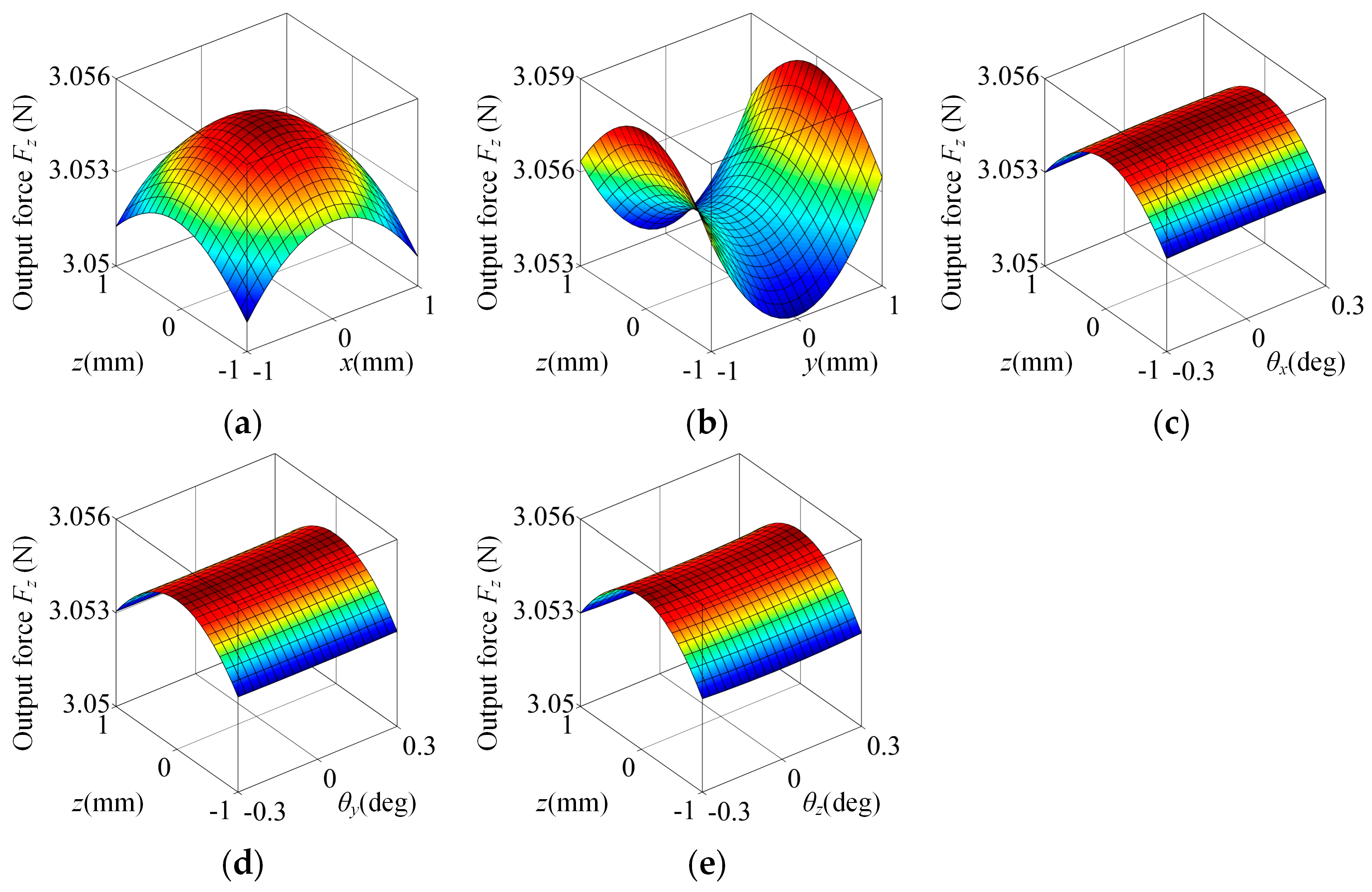
Figure 6 shows the characteristic of the HMF-VCA’s output force Fz varied with the mover’s motion. From Figure 6, the nominal output force Fz is about 3.055N, and it is almost constant in its full stroke. The variation of Fz caused by the translation or rotation in z, x, y, θx, θy, θz are as small as 0.059% mm−1, 0.076% mm−1, 0.121% mm−1, 0.0044% deg−1, 0.0022% deg−1, 0.0092% deg−1, respectively. This proves that the proposed structure is very effective at reducing the fluctuation of the output force Fz.
3.2. Parasitic Force
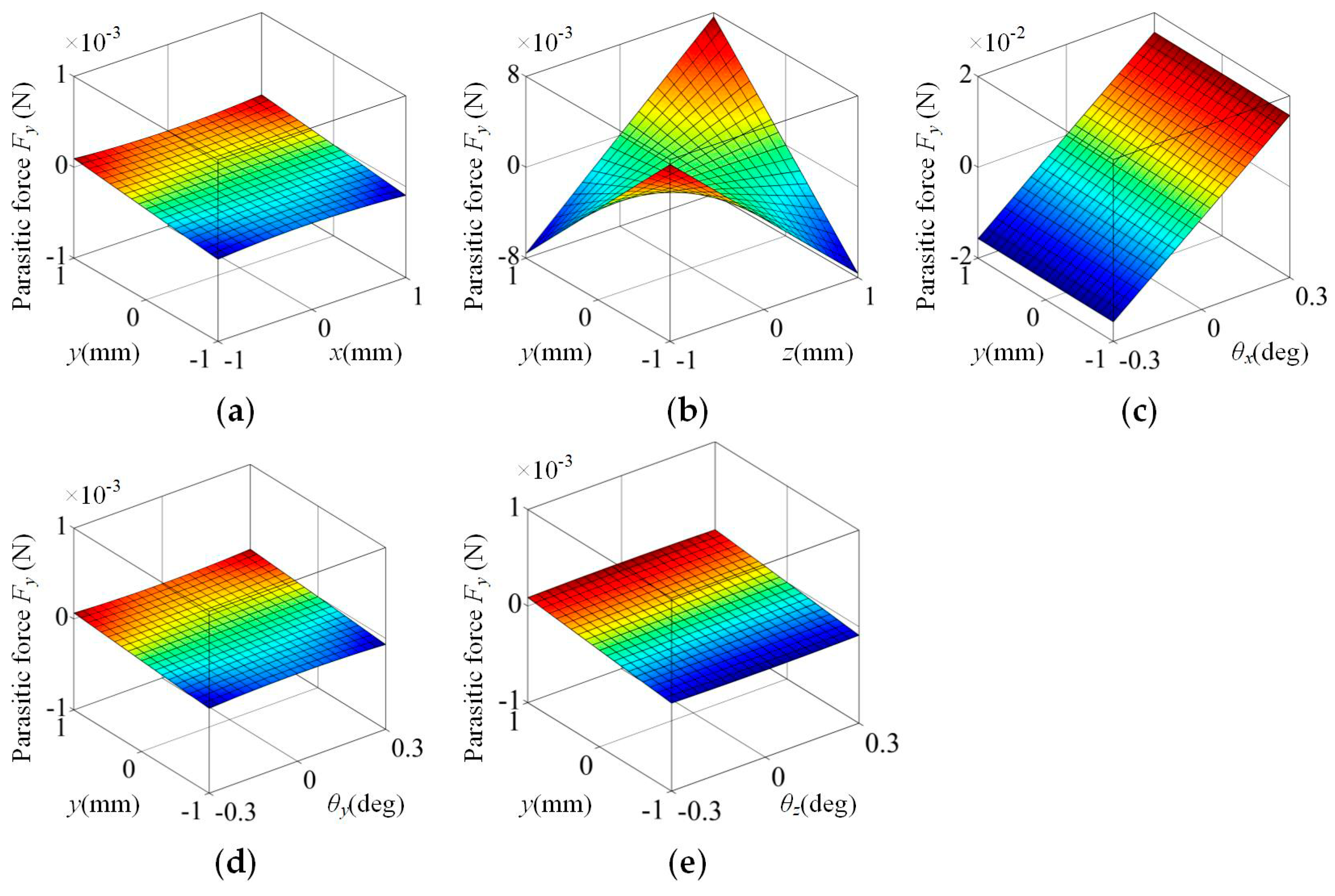
Besides the characteristic of the output force Fz, we are also concerned with the characteristics of the parasitic force Fx and Fy, because these two forces are undesirable and would increase the complexity of the control system; thus, these two forces are expected to be as small as possible.
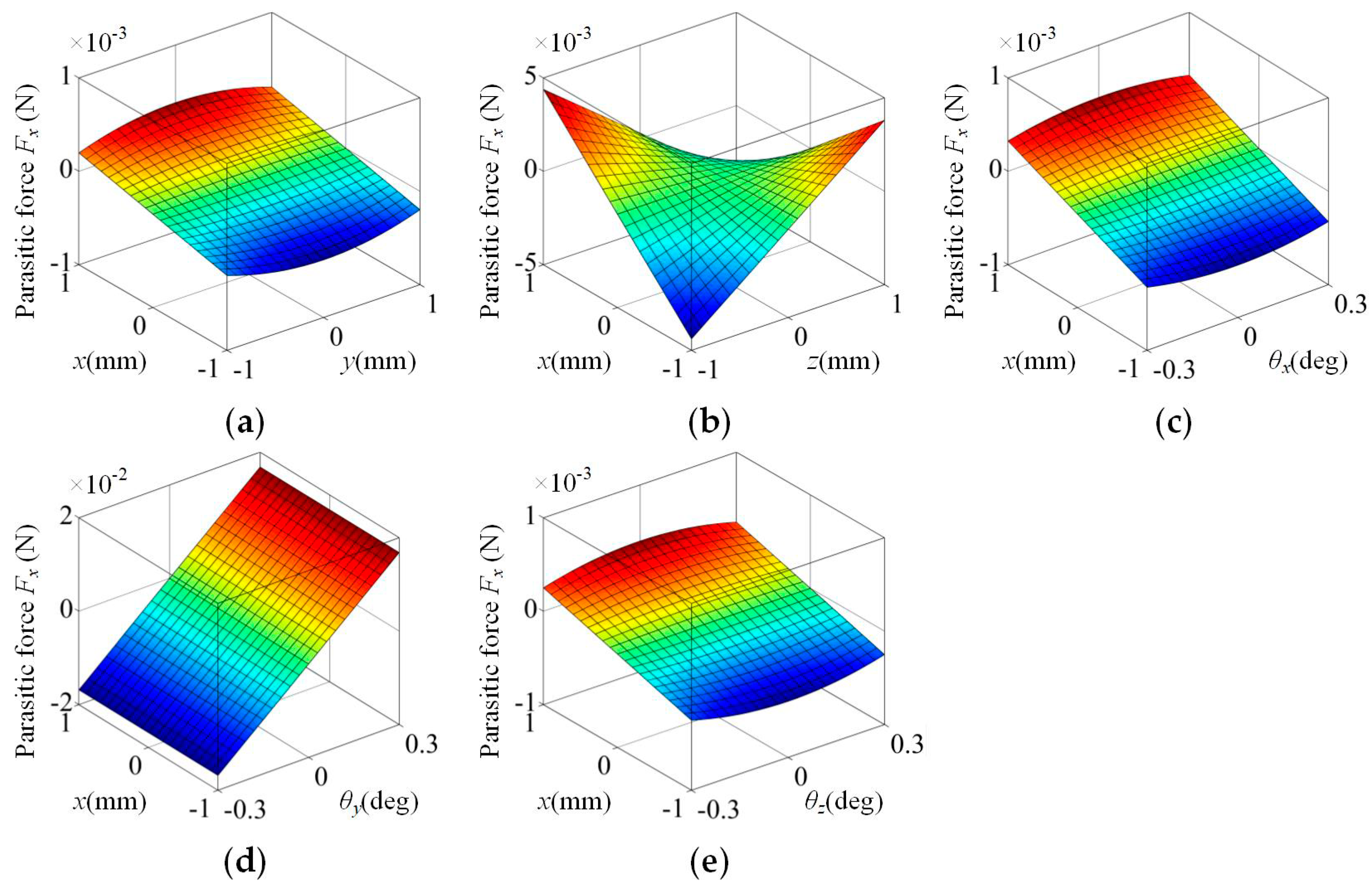
Figure 7 and Figure 8 show the characteristic of the HMF-VCA’s parasitic force Fx and Fy varied with the mover’s motion. From Figure 7, the parasitic force Fx is approximately proportional to z, θy, and it is almost insensitive to the variation of y, θx, θz. The variations of Fx caused by z, θy are 0.143% mm−1, 1.84% deg−1, respectively.
Compared with the fluctuation of output force Fz, the fluctuation of parasitic force Fx is much larger. However, we can still say that it has good performance based on the following two reasons. The first reason is that the parasitic force Fx is approximately proportional to z, θy. In this case, the adverse effect of parasitic force Fx can be eliminated by adding a compensation coefficient in the control system easily. The second reason is that, in general, the maximum of θy in an actual magnetic levitation fine positioning stage (MLFPS) is much smaller than the value set in the simulation. Thus, the parasitic force Fx caused by the rotation around y axis will not be as large as in Figure 7d.
From Figure 8, the parasitic force Fy is approximately proportional to z, θx, and it is almost insensitive to the variation of x, θy, θz. The variation of Fy caused by z, θx are 0.250% mm−1, 1.71% deg−1, respectively.
Similar to the analysis of parasitic force Fx, although the fluctuation of parasitic force Fy is much larger than the fluctuation of output force Fz, we can still say that it has good performance based on the same two reasons.
3.3. Parasitic Torque
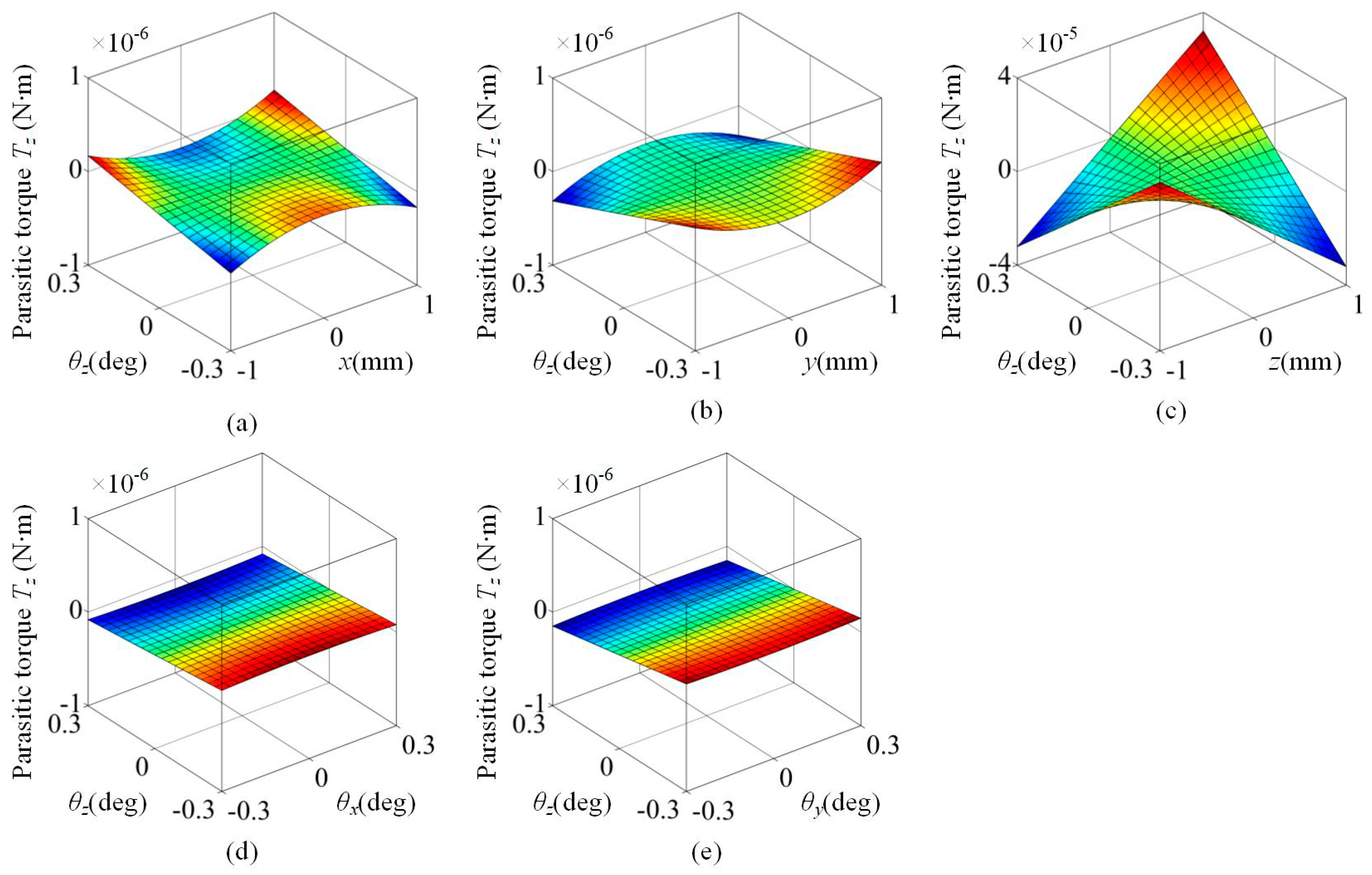
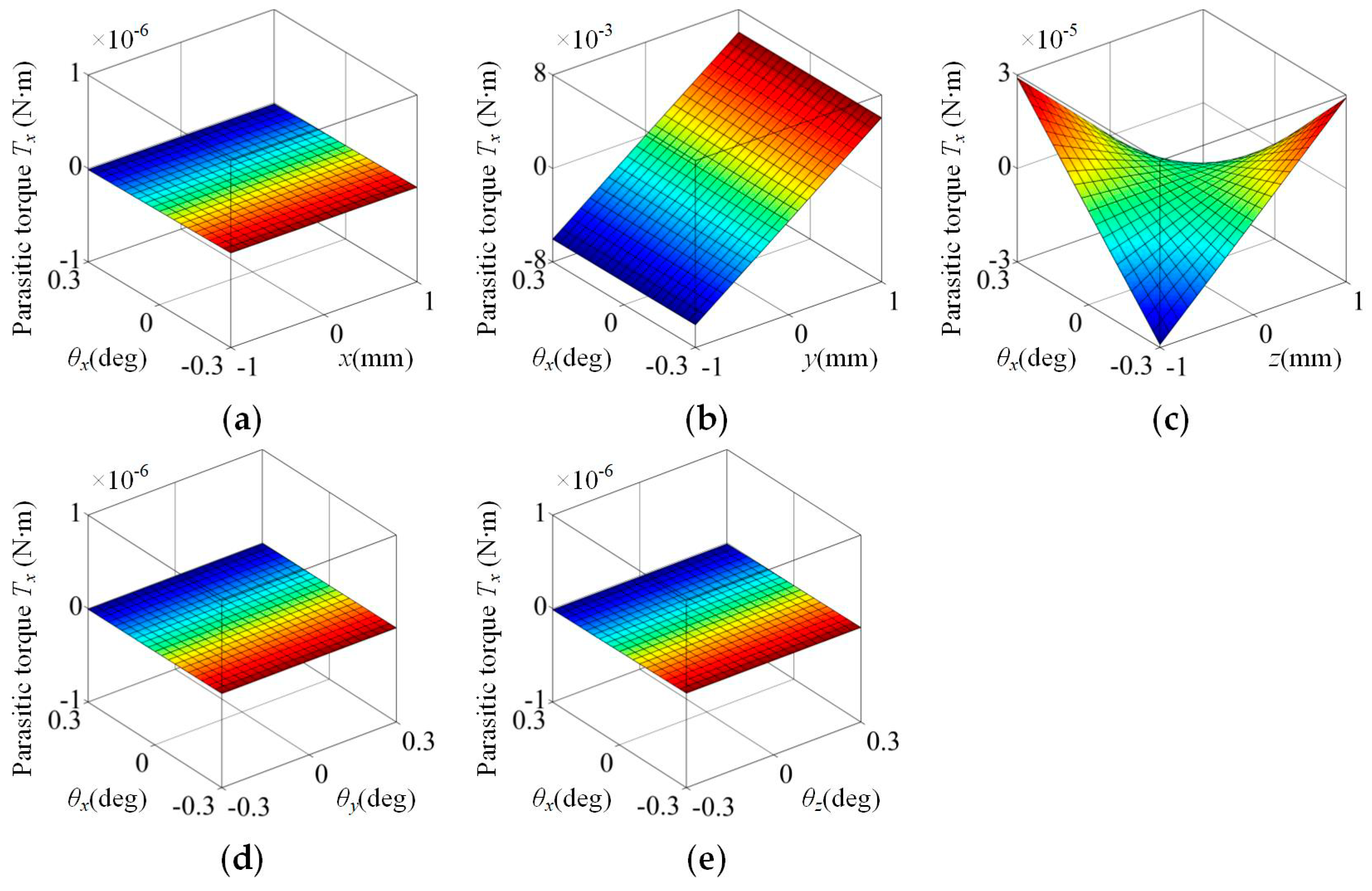
The characteristics of the parasitic torque Tz, Tx and Ty are also taken into account because of their adverse effect on the system, similar to the parasitic force. Figure 9, Figure 10 and Figure 11 show the characteristic of the HMF-VCA’s parasitic torque Tz, Tx and Ty varied with the mover’s motion.
Compared with the variation of force, the variation of torque is less obvious. Only when θz and z change simultaneously will the parasitic torque Tz change little, as shown in Figure 9, and the parasitic torque Tz is approximately proportional to θz, z. Thus, its adverse effect can also be eliminated by adding a compensation coefficient in the control system easily.
At the same time, from Figure 10 and Figure 11, the parasitic toque Tx is approximately proportional to the variation of y, z, θx, and the parasitic toque Ty is approximately proportional to the variation of x, z, θy. The most significant variations are the variation of Tx caused by y and the variation of Ty caused by x, which are in fact caused by the offset of the output force, and can be solved in the decoupling process of multi-degree-of-freedom system. Thus, they will not increase the control system’s complexity. Consequently, the torque characteristic could be ignored in the design and optimization progress.
3.4. Parametric Analysis
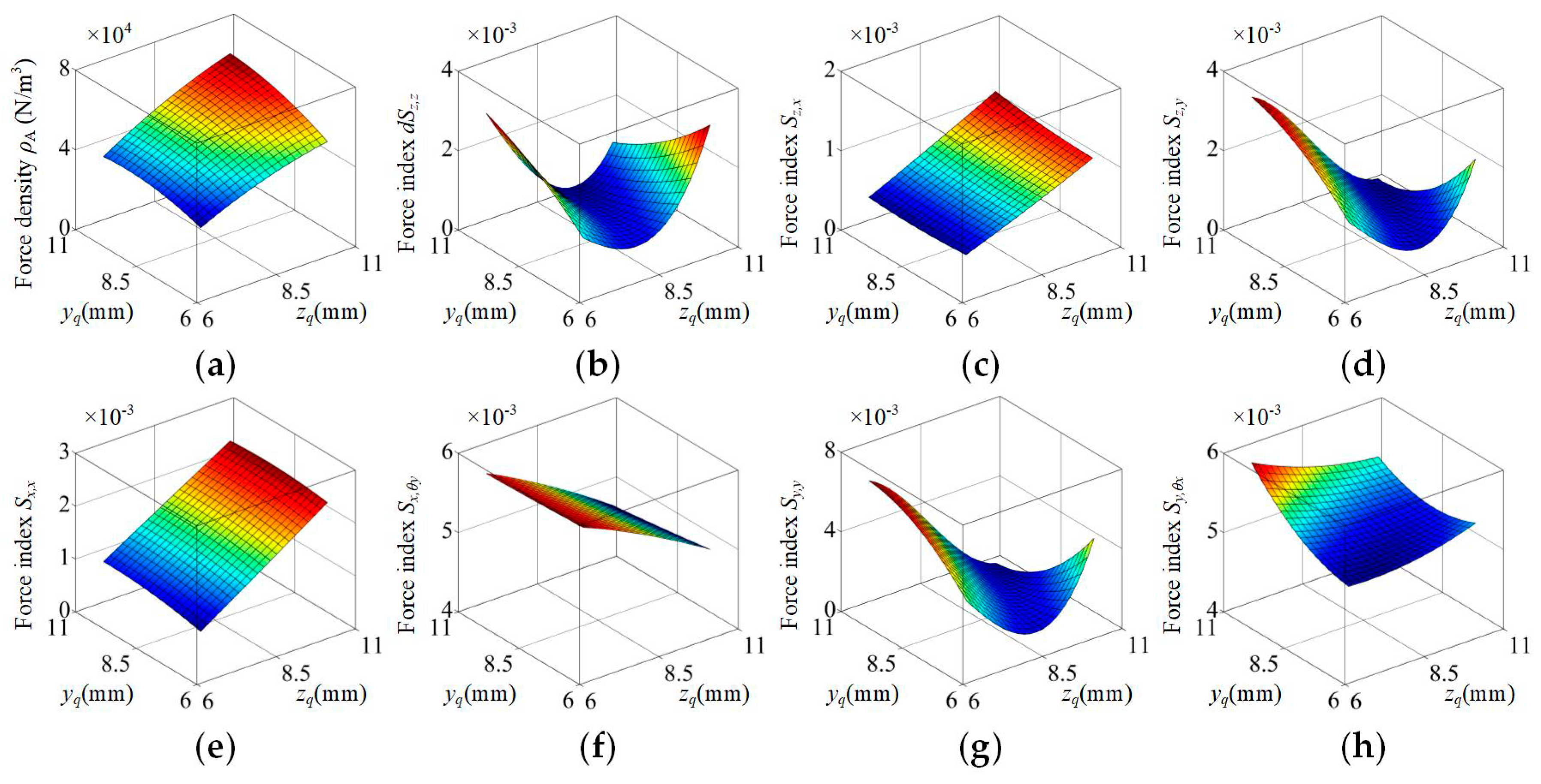
Based on the above analysis of Figure 6, Figure 7, Figure 8, Figure 9, Figure 10 and Figure 11, the HMF-VCA possesses excellent force uniformity as expected. Actually, its performance can be further improved. Several important or relatively large indexes are chosen to be further optimized, i.e., the variation of Fz caused by z, x, y, the variation of Fx caused by z, θy, and the variation of Fy caused by z, θx. In the following text, these force indexes are abbreviated as Sz,z, Sz,x, Sz,y, Sx,z, Sx,θy, Sy,z, Sy,θx, respectively. In addition, considering the volume limitation in some applications, the HMF-VCA’s force density (output force per active volume ρA) should be also considered and optimized, and it is calculated with the following formula:
where VA is the active volume of the HMF-VCA, and all the other variables are defined in Figure 5 and Table 1.
To find a useful optimization method for future design, the influence of structural parameters on force density and uniformity are analyzed. For maximum space utilization, there is a geometric relationship for the parameters of coils, wc + tc + 2 δ = yq + zq, and considering the HMF-VCA’s stroke and manufacturability, δ, ws, ts are chosen to be 3 mm, 2 mm, 2 mm, respectively. Figure 12, Figure 13 and Figure 14 show the HMF-VCA’s force density and uniformity varied with important structural parameters.
Figure 12 shows the HMF-VCA’s force density and uniformity varied with yq and zq. From Figure 12, the increase of both yq and zq will lead to the increase of force density ρA; however, only when yq and zq are in particular intervals will the indexes Sz,z, Sz,y, Sy,z obtain small values. Thus, for the applications where the volume is not limited, yq and zq should be set to be the values where Sz,z, Sz,y, Sy,z obtain small values as shown in Figure 12b,d,g,h, and for the applications where the volume is limited strictly, yq and zq should be set to be the values where ρA is larger as according to Figure 12a.
Figure 13 shows the HMF-VCA’s force density and uniformity varied with wm and tm. From Figure 13, it is suggested that a small wm will be useful for obtaining high force density ρA; however, a larger wm will lead to better force uniformity. Furthermore, the influence of tm on force density and uniformity is very small. Thus, similar to the choice of yq and zq, wm should be designed carefully according to the requirements of volume limitation and force uniformity.
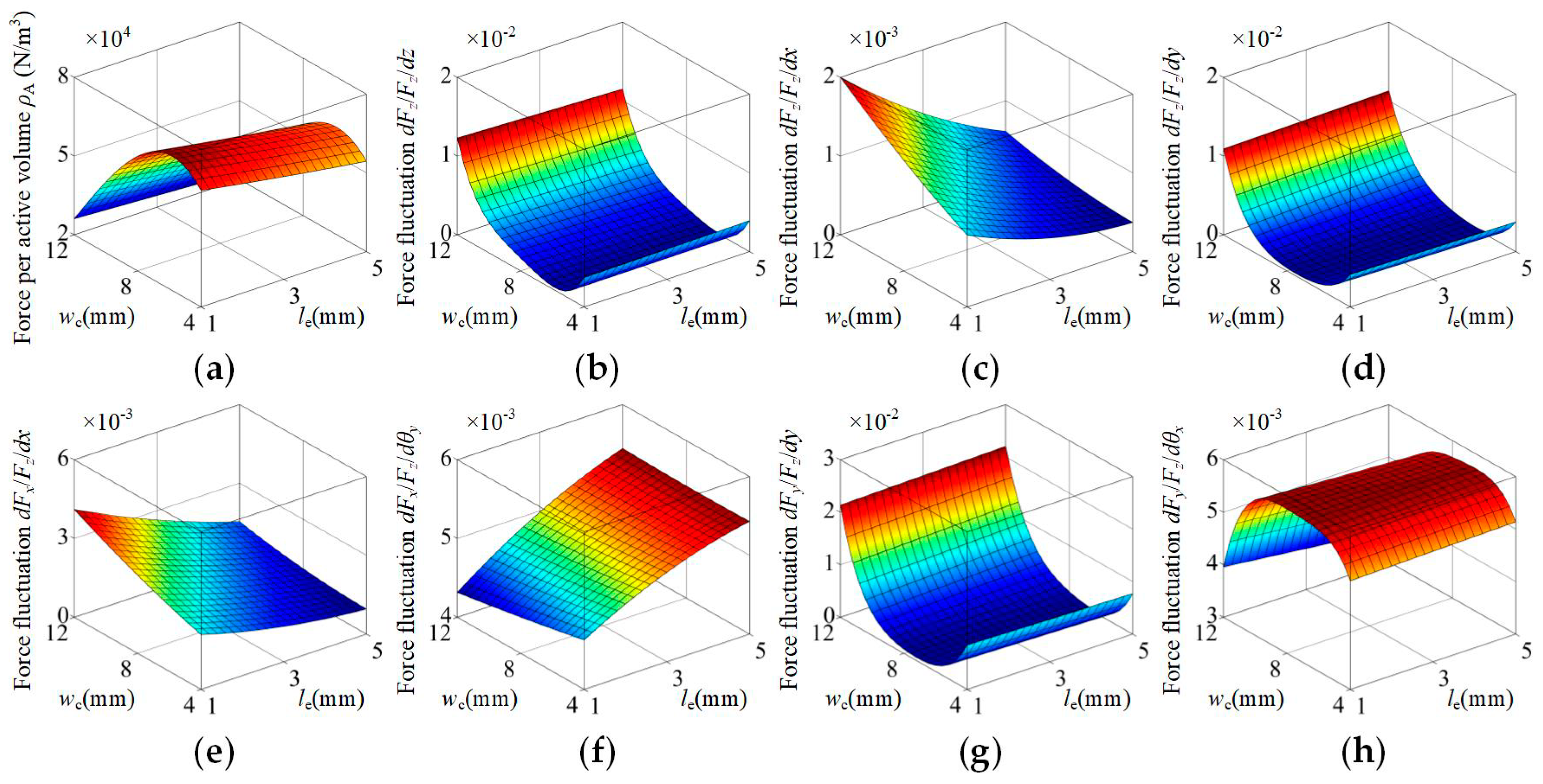
Figure 14 shows the HMF-VCA’s force density and uniformity varied with wc and le. From Figure 14, it is recommended that the parameter wc be about 6 mm, because the force density and uniformity are improved at the same time. In addition, the increase of parameter ls can decrease Sz,x, Sx,z, but this will also decrease ρA and increase Sx,θy.
In conclusion, the change of most of the structural parameters will bring advantages as well as disadvantages, and it is contradictory to reach highest force density and best force uniformity at the same time. Consequently, the researchers should choose reasonable structural parameters according to the actual requirements of force density and uniformity. Further optimization can be achieved through the multi-parameter optimization method. In this paper, we focus on proving the proposed new topology can achieve good force uniformity, and demonstrating that a topology with good force uniformity can be designed through field analysis and adjusting dimensions. Therefore, the content of multi-parameters optimization is not included in the paper.
4. Performance Test and Comparison
A prototype is constructed and tested to validate the performance of the proposed topology. The test installation is made up of a position adjuster, a force sensor, a high-precision multimeter, and a support, as shown in Figure 15a.
The measured output force is 2.956 N, as shown in Figure 15b. Compared to the FEA value of 3.055 N, the deviation is about 3.24%, and the general trend is in good agreement with the FEA predications. The reasons for the deviation between the measured value and the FEA value are discussed below. The first reason may be that the coils are considered to completely fill the slots in the stator; however, the actual coils are a little smaller than those in the simulation because of the manufacturing process. The second reason may be that the magnets are not perfectly magnetized, in other words, the remanence may be slightly smaller than the simulation value. The third reason may be the deviation of geometric parameters.
5. Discussion
The HMF-VCA is compared with conventional VCAs [18], as listed in Table 2. It should be noted that the stroke of VCAs in [18] is set to be ±5 × 10⁻⁴ m and ±5 × 10⁻³ rad; thus, the HMF-VCA’s performance is also calculated in the same stroke. From Table 2, the HMF-VCA’s variation of Fz caused by z, θz and variation of Fx caused by x, y are much lower than the other VCAs. Although the HMF-VCA’s variation of Fz caused by θx or θy is larger than the VCAs with one square or circular magnet, the value of 0.001% is small enough for high-precision applications. In addition, the HMF-VCA’s variation of Fx and Fy caused by θx and θy is between the VCA with four rectangular magnets and the VCAs with one square or circular magnet. On the whole, the HMF-VCA features much better force uniformity than conventional VCAs.
6. Conclusions
In this paper, a novel HMF-VCA has been investigated. Its six-degree-of-freedom force and torque characteristics, as well as the influence of structural parameters on force density and uniformity, are studied by 3-D FEA. The results show that the proposed topology possesses the advantage of excellent force uniformity, and is suitable for MHPS applications.
Author Contributions
Conceptualization, Y.Z.; methodology, Y.Z.; formal analysis, Y.Z.; validation, Y.Z., H.Z., L.Z. and L.W.; investigation, Y.Z.; data curation, Y.Z.; writing—original draft preparation, Y.Z.; writing—review and editing, Y.Z.; project administration, B.K.; funding acquisition, Y.Z., B.K., H.Z., L.Z. and L.W.
Funding
This research was funded by National Natural Science Foundation of China, grant number 51877052, Research and Development Foundation of Scientific and Technological Achievements for Heilongjiang Provincial Universities, grant number TSTAU-C2018002 and CAST-BISEE Foundation, grant number CAST-BISEE2017-007.
Conflicts of Interest
The authors declare no conflict of interest.
References
- Rovers, J.M.M.; Jansen, J.W.; Compter, J.C.; Lomonova, E.A. Analysis method of the dynamic force and torque distribution in the magnet array of a commutated magnetically levitated planar actuator. IEEE Trans. Ind. Electron. 2012, 59, 2157–2166. [Google Scholar] [CrossRef]
- Xu, Q. Design and development of a compact flexure-based XY precision positioning system with centimeter range. IEEE Trans. Ind. Electron. 2014, 61, 893–903. [Google Scholar] [CrossRef]
- Zhang, H.; Kou, B.; Zhang, H.; Jin, Y. A three-degree-of-freedom short-stroke Lorentz-force-driven planar motor using a Halbach permanent-magnet array with unequal thickness. IEEE Trans. Ind. Electron. 2015, 62, 3640–3650. [Google Scholar] [CrossRef]
- Valiente-Blanco, I.; Diez-Jimenez, E.; Sanchez-Garcia-Casarrubios, J.; Perez-Diaz, J.L. Improving Resolution and Run Outs of a Superconducting Noncontact Device for Precision Positioning. IEEE-ASME Trans. Mechatron. 2015, 20, 1992–1996. [Google Scholar] [CrossRef]
- Perez-Diaz, J.L.; Valiente-Blanco, I.; Diez-Jimenez, E.; Sanchez-Garcia-Casarrubios, J. Superconducting Non-Contact Device for Precision Positioning in Cryogenic Environments. IEEE-ASME Trans. Mechatron. 2014, 19, 598–605. [Google Scholar] [CrossRef]
- Devasia, S.; Eleftheriou, E.; Moheimani, S.O.R. A survey of control issues in nanopositioning. IEEE Trans. Control Syst. Technol. 2007, 15, 802–823. [Google Scholar] [CrossRef]
- Xie, Y.; Tan, Y.; Dong, R. Nonlinear modeling and decoupling control of XY micropositioning stages with piezoelectric actuators. IEEE-ASME Trans. Mechatron. 2013, 18, 821–832. [Google Scholar] [CrossRef]
- Ueda, Y.; Ohsaki, H. A planar actuator with a small mover traveling over large yaw and translational displacements. IEEE Trans. Magn. 2008, 44, 609–616. [Google Scholar] [CrossRef]
- Zhu, H.; Teo, T.J.; Pang, C.K. Design and modeling of a six-degree-of-freedom magnetically levitated positioner using square coils and 1-D Halbach arrays. IEEE Trans. Ind. Electron. 2017, 64, 440–450. [Google Scholar] [CrossRef]
- Jiang, Y.; Zhu, Y.; Yang, K.; Hu, C.; Yu, D. A data-driven iterative decoupling feedforward control strategy with application to an ultraprecision motion stage. IEEE Trans. Ind. Electron. 2015, 62, 620–627. [Google Scholar] [CrossRef]
- Fung, R.F.; Hsu, Y.L.; Huang, M.S. System identification of a dual-stage XY precision positioning table. Precis. Eng. 2009, 33, 71–80. [Google Scholar] [CrossRef]
- Choi, Y.M.; Gweon, D.G. A high-precision dual-servo stage using Halbach linear active magnetic bearings. IEEE-ASME Trans. Mechatron. 2011, 16, 925–931. [Google Scholar] [CrossRef]
- Shan, X.; Kuo, S.K.; Zhang, J.; Menq, C.H. Ultra precision motion control of a multiple degrees of freedom magnetic suspension stage. IEEE-ASME Trans. Mechatron. 2002, 7, 67–78. [Google Scholar] [CrossRef]
- Chen, M.Y.; Lin, T.B.; Hung, S.K.; Fu, L.C. Design and experiment of a macro–micro planar maglev positioning system. IEEE Trans. Ind. Electron. 2012, 59, 4128–4139. [Google Scholar] [CrossRef]
- Kuo, S.K.; Meng, C.H. Modeling and control of a six-axis precision motion control stage. IEEE-ASME Trans. Mechatron. 2005, 10, 50–59. [Google Scholar] [CrossRef]
- Verma, S.; Kim, W.J.; Shakir, H. Multi-axis maglev nanopositioner for precision manufacturing and manipulation applications. IEEE Trans. Ind. Appl. 2005, 41, 1159–1167. [Google Scholar] [CrossRef]
- Verma, S.; Shakir, H.; Kim, W.J. Novel electromagnetic actuation scheme for multiaxis nanopositioning. IEEE Tran. Magn. 2006, 42, 2052–2062. [Google Scholar] [CrossRef]
- Vrijsen, N.H.; Jansen, J.W.; Lomonova, E.A. Comparison of linear voice coil and reluctance actuators for high-precision applications. In Proceedings of the 14th International Power Electronics and Motion Control Conference EPE-PEMC 2010, Ohrid, Macedonia, 6–8 September 2010. [Google Scholar]
- Zhou, Y.; Kou, B.; Zhang, H.; Luo, J.; Gan, L. Force Characteristic Analysis of a Linear Magnetic Bearing with Rhombus Magnet Array for Magnetic Levitation Positioning System. IEEE Trans. Magn. 2017, 53, 6500407. [Google Scholar] [CrossRef]
- Kremers, M.F.; Paulides, J.J.; Ilhan, E.; Janssen, J.L.; Lomonova, E.A. Relative Permeability in a 3D Analytical Surface Charge Model of Permanent Magnets. IEEE Trans. Magn. 2013, 49, 2299–2302. [Google Scholar] [CrossRef] [Green Version]
Figure 1.
Structure of the HMF-VCA and MLFPS. (a) 3-D view of the MLFPS. (b) 3-D view of the HMF-VCA. (c) Sectional view of the HMF-VCA.
Figure 1.
Structure of the HMF-VCA and MLFPS. (a) 3-D view of the MLFPS. (b) 3-D view of the HMF-VCA. (c) Sectional view of the HMF-VCA.

Figure 2.
Structure of the conventional VCAs. (a) Structure of the FR-VCA. (b) Structure of the OR-VCA. (c) Structure of the OS-VCA. (d) Structure of the OC-VCA.
Figure 2.
Structure of the conventional VCAs. (a) Structure of the FR-VCA. (b) Structure of the OR-VCA. (c) Structure of the OS-VCA. (d) Structure of the OC-VCA.

Figure 3.
Magnetic field comparison between the HMF-VCA and conventional VCAs. (a) Magnetic field of the FR-VCA. (b) Magnetic field of the OR-VCA. (c) Magnetic field of the HMF-VCA. (d) Magnetic field component By of the FR-VCA. (e) Magnetic field component By of the OR-VCA. (f) Magnetic field component By of the HMF-VCA. (g) Output force Fz of the FR-VCA. (h) Output force Fz of the OR-VCA. (i) Output force Fz of the HMF-VCA.

Figure 4.
Motion, force and torque of the HMF-VCA. (a) Six-degree-of-freedom motion of the HMF-VCA. (b) The force and torque acting on the mover of the HMF-VCA.
Figure 4.
Motion, force and torque of the HMF-VCA. (a) Six-degree-of-freedom motion of the HMF-VCA. (b) The force and torque acting on the mover of the HMF-VCA.

Figure 5.
Structural parameters of the HMF-VCA. (a) 3-D view. (b) 2-D view.

Figure 6.
Output force Fz characteristic of the HMF-VCA varied with the mover’s motion. (a) Fz vs. z and x. (b) Fz vs. z and y. (c) Fz vs. z and θx. (d) Fz vs. z and θy. (e) Fz vs. z and θz.
Figure 6.
Output force Fz characteristic of the HMF-VCA varied with the mover’s motion. (a) Fz vs. z and x. (b) Fz vs. z and y. (c) Fz vs. z and θx. (d) Fz vs. z and θy. (e) Fz vs. z and θz.

Figure 7.
Parasitic force Fx characteristic of the HMF-VCA varied with the mover’s motion. (a) Fx vs. x and y. (b) Fx vs. x and z. (c) Fx vs. x and θx. (d) Fx vs. x and θy. (e) Fx vs. x and θz.
Figure 7.
Parasitic force Fx characteristic of the HMF-VCA varied with the mover’s motion. (a) Fx vs. x and y. (b) Fx vs. x and z. (c) Fx vs. x and θx. (d) Fx vs. x and θy. (e) Fx vs. x and θz.

Figure 8.
Parasitic force Fy characteristic of the HMF-VCA varied with the mover’s motion. (a) Fy vs. y and x. (b) Fy vs. y and z. (c) Fy vs. y and θx. (d) Fy vs. y and θy. (e) Fy vs. y and θz.
Figure 8.
Parasitic force Fy characteristic of the HMF-VCA varied with the mover’s motion. (a) Fy vs. y and x. (b) Fy vs. y and z. (c) Fy vs. y and θx. (d) Fy vs. y and θy. (e) Fy vs. y and θz.

Figure 9.
Parasitic torque Tz characteristic of the HMF-VCA varied with the mover’s motion. (a) Tz vs. θz and x. (b) Tz vs. θz and y. (c) Tz vs. θz and z. (d) Tz vs. θz and θx. (e) Tz vs. θz and θy.
Figure 9.
Parasitic torque Tz characteristic of the HMF-VCA varied with the mover’s motion. (a) Tz vs. θz and x. (b) Tz vs. θz and y. (c) Tz vs. θz and z. (d) Tz vs. θz and θx. (e) Tz vs. θz and θy.

Figure 10.
Parasitic torque Tx characteristic of the HMF-VCA varied with the mover’s motion. (a) Tx vs. θx and x. (b) Tx vs. θx and y. (c) Tx vs. θx and z. (d) Tx vs. θx and θy. (e) Tx vs. θx and θz.
Figure 10.
Parasitic torque Tx characteristic of the HMF-VCA varied with the mover’s motion. (a) Tx vs. θx and x. (b) Tx vs. θx and y. (c) Tx vs. θx and z. (d) Tx vs. θx and θy. (e) Tx vs. θx and θz.

Figure 11.
Parasitic torque Ty characteristic of the HMF-VCA varied with the mover’s motion. (a) Ty vs. θy and x. (b) Ty vs. θy and y. (c) Ty vs. θy and z. (d) Ty vs. θy and θx. (e) Ty vs. θy and θz.
Figure 11.
Parasitic torque Ty characteristic of the HMF-VCA varied with the mover’s motion. (a) Ty vs. θy and x. (b) Ty vs. θy and y. (c) Ty vs. θy and z. (d) Ty vs. θy and θx. (e) Ty vs. θy and θz.

Figure 12.
Force density and uniformity of the HMF-VCA varied with structural parameters yq and zq. (a) Force density ρA. (b) Variation of Fz caused by z. (c) Variation of Fz caused by x. (d) Variation of Fz caused by y. (e) Variation of Fx caused by x. (f) Variation of Fx caused by θy. (g) Variation of Fy caused by y. (h) Variation of Fy caused by θx.

Figure 13.
Force density and uniformity of the HMF-VCA varied with structural parameters wm and tm. (a) Force density ρA. (b) Variation of Fz caused by z. (c) Variation of Fz caused by x. (d) Variation of Fz caused by y. (e) Variation of Fx caused by x. (f) Variation of Fx caused by θy. (g) Variation of Fy caused by y. (h) Variation of Fy caused by θx.

Figure 14.
Force density and uniformity of the HMF-VCA varied with structural parameters ws and te. (a) Force density ρA. (b) Variation of Fz caused by z. (c) Variation of Fz caused by x. (d) Variation of Fz caused by y. (e) Variation of Fx caused by x. (f) Variation of Fx caused by θy. (g) Variation of Fy caused by y. (h) Variation of Fy caused by θx.

Figure 15.
Test installation, and comparison between the test result and FEA result. (a) Test installation. (b) Test result of output force Fz vs. z and x. (c) Test result of output force Fz vs. z and y. (d) Comparison between the test result and FEA result of Fz vs. z and x. (e) Comparison between the test result and FEA result of Fz vs. z and y.


Table 1.
Structural parameters of the HMF-VCA.
| Symbol | Quantity | Data |
|---|---|---|
| lm | length of mover magnet | 40 mm |
| wm | width of mover magnet | 18 mm |
| tm | thickness of mover magnet | 8 mm |
| yq | position of mover magnet in the y axis | 8 mm |
| zq | position of mover magnet in the z axis | 8 mm |
| θ | inclined angle of mover magnet | 45° |
| lc | length of stator coil | 60 mm |
| wc | width of stator coil | 6 mm |
| tc | thickness of stator coil | 5 mm |
| ls | adjustable length of stator coil | 4 mm |
| ws | width of space between stator coils | 2 mm |
| ts | thickness of space between stator coils | 2 mm |
Table 2.
Performance comparison of VCAs.
| Output and Parasitic Force and Torque Characteristic | HMF-VCA | VCA Four Rectangular Magnets | VCA One Rectangular Magnet | VCA One Square Magnet | VCA One Circular Magnet |
|---|---|---|---|---|---|
| Variation of Fz caused by z, θz | 0.018% | 1.6% | 1.3% | 8% | ≈8% |
| Variation of Fz caused by θx, θy | 0.001% | 0.05% | - | 0.0005% | ≈0.0005% |
| Variation of Fx caused by x, y | 0.006% | - | 9% | 4% | ≈4% |
| Variation of Fx caused by θx, θy | 0.55% | 0.17% | - | 0.6% | ≈0.6% |
| Variation of Fy caused by θx, θy | 0.51% | 0.27% | - | 4% | ≈4% |
© 2019 by the authors. Licensee MDPI, Basel, Switzerland. This article is an open access article distributed under the terms and conditions of the Creative Commons Attribution (CC BY) license (http://creativecommons.org/licenses/by/4.0/).
Share and Cite
MDPI and ACS Style
Zhou, Y.; Kou, B.; Zhang, H.; Zhang, L.; Wang, L. Design, Analysis and Test of a Hyperbolic Magnetic Field Voice Coil Actuator for Magnetic Levitation Fine Positioning Stage. Energies 2019, 12, 1830. https://doi.org/10.3390/en12101830
AMA Style
Zhou Y, Kou B, Zhang H, Zhang L, Wang L. Design, Analysis and Test of a Hyperbolic Magnetic Field Voice Coil Actuator for Magnetic Levitation Fine Positioning Stage. Energies. 2019; 12(10):1830. https://doi.org/10.3390/en12101830
Chicago/Turabian StyleZhou, Yiheng, Baoquan Kou, He Zhang, Lu Zhang, and Likun Wang. 2019. "Design, Analysis and Test of a Hyperbolic Magnetic Field Voice Coil Actuator for Magnetic Levitation Fine Positioning Stage" Energies 12, no. 10: 1830. https://doi.org/10.3390/en12101830
Note that from the first issue of 2016, this journal uses article numbers instead of page numbers. See further details here.