Article

Performance Analysis of Single-Phase Electrical Machine for Military Applications

by
Aswin Uvaraj Ganesan
1,
Sathyanarayanan Nandhagopal
1,
Arvind Shiyam Venkat
1,
Sanjeevikumar Padmanaban
2,
John K. Pedersen
3,
Lenin Natesan Chokkalingam
1,* and
Zbigniew Leonowicz
4
1
School of Electrical Engineering, Vellore Institute of Technology (VIT) University, Chennai, Tamilnadu 600127, India
2
Department of Energy Technology, Aalborg University, Esbjerg 6700, Denmark
3
Department of Energy Technology, Aalborg University, Aalborg 9220, Denmark
4
Department of Electrical Engineering, Wroclaw University of Technology, Wyb. Wyspianskiego 27, I-7, 50370 Wroclaw, Poland
*
Author to whom correspondence should be addressed.
Energies 2019, 12(12), 2285; https://doi.org/10.3390/en12122285
Submission received: 8 May 2019 / Revised: 20 May 2019 / Accepted: 27 May 2019 / Published: 14 June 2019
(This article belongs to the Special Issue Electrical Machine Design)

Abstract

:
A permanent magnet assisted synchronous reluctance generator (PMA-SynRG) and an induction generator (IG) were compared for portable generator applications. PMA-SynRG with two rotor configurations, namely rotors with ferrite magnet and NdFeB, were designed. Furthermore, a design strategy for both PMA-SynRG and IG is presented with their geometrical dimensions. The machine was designed and results were analyzed using finite element analysis. Results such as flux density, open circuit and full load voltages, torque in generating mode, weight comparison and detailed cost analysis were investigated. In addition, thermal analysis for various ambient conditions (−40 °C, +30 °C, +65 °C) was evaluated for both PMA-SynRG and IG. Furthermore, acoustic versus frequency plot and acoustic pressure level were investigated for both the generators. Finally, the results confirmed that the machine with a higher power-to-weight ratio was the right choice for military applications.

1. Introduction

A portable generator, or compact generator, is a gasoline-driven engine, alternating current (AC) generator. The power range of these types of generators lies between 1–11 kW, depending on industry standards [1]. It is designed to supply electrical power for lighting, appliances, tools and low or medium power equipments [2]. The dissembled view of a portable generator is presented in Figure 1. In recent periods, the need for compact generators is largely expanded [3]. This kind of generator can be more useful during power failures through unavoidable circumstances [4]. Portable generators use small engines in which the spinning shaft of the engine creates an alternating magnetic field through a coil which induces voltage [5]. Light weight and high power are the key factors of portable generators.
The permanent magnet synchronous generators (PMSG) are an appropriate choice for portable generators in military usage, due to their high power density, compact size and high efficiency. Permanent magnet (PM) is a replacement of field winding in conventional machines [6].
Rare earth magnets are commonly divided into light rare earth magnets and less-available heavy rare earth magnets [7]. The most plenteous rare earth magnets are lanthanum, cerium, and neodymium, which are all considered light earth magnets, along with praseodymium and samarium [8].
The most common PMs are samarium cobalt and neodymium-iron-boron. Samarium cobalt magnets perform well at higher temperatures but are brittle, which confines magnet size and can cause issues with certain motoring applications [9].
Neodymium–iron–boron magnets are significantly stronger than samarium cobalt magnets. As a result, their size is not as limited and they are more appropriate for generator applications. These magnets normally have two to four percent of dysprosium to enhance their temperature resistance [4]. Nearly 90% of high-value rare earth magnets are from China [10], which makes the design using PMs very costly [11].
The Permanent Magnet Synchronous Reluctance Generator (PMA-SynRG) is similar to a synchronous reluctance generator and costs less than the PMSG [12], which is also used in various applications [13]. In a PMA-SynRG, PMs are placed in the flux barriers, creating a magnet torque which supports and increases the torque characteristics [14]. Moreover, the usage of PMs will increase the power factor in combination with SynRG. The volume, type, and positioning of PMs differ widely from PMA-SynRG [15]. The magnet material used is of rare earth magnets and ferrite magnets. Ferrite magnets, also known as ceramic magnets, are alloys of Barium (Ba) or Strontium (Sr) with ferrite (Fe2O3). The materials have a linear demagnetization characteristic and cost less which makes them the most common magnets for general purpose applications [16] (refer to Appendix A Table A1).
Similarly, the induction generator (IG) is also a better choice for portable generators [17] where weight is a major concern. Ruggedness, simple design, robustness, lower cost, and reduced maintenance are the most important benefits of IG. The presence of residual flux in the rotor core and the excitation capacitance self-excites IG, causing the stator voltage to build up [18].
This research work concentrates mainly on the performance and weight comparison of PMA-SynRG and IG to meet the military standards. Three generator topologies (ferrite rotor, NdFeB rotor and IG) were designed and investigated. The rotor with an NdFeB magnet performed better and has a 21.57% higher power–to–weight ratio in comparison to IG. Furthermore, a detailed cost analysis was provided disclosing that IG reduced costs in comparison to the topology of other generators. The noise levels of both the NdFeB rotor and IG are of military standards. Finally, these two generator configurations confirmed a 20%–30% rate of reduced weight compared with an existing 5 kW generator in the military applications.
Section 2 explains the constraints and requirements of a portable generator in military applications. Section 3 deals with the design strategy of PMA-SynRG and IG. In Section 4, the stator and rotor geometrical configurations, output voltage waveform, torque in generating mode, weight comparison cost analysis, and overall performance characteristics are evaluated using finite element analysis (FEA). Section 5 covers the thermal analysis for various ambient temperatures and also highlights the acoustic pressure level of both generators. Section 6 deals with a detailed cost estimation of the machine. Finally, Section 7 concludes with the kW/kg difference of NdFeB rotor and other configurations.

2. Constraints of Portable Generator in Military Applications

Size, weight, and price are the key factors in designing an electric machine for military applications. Prominent performance developments in IG and price deductions of PM materials in PMA-SynRG make them more appropriate for military usage. IG and PMA-SynRG provide following features, such as reduced weight and size, simple mechanical structure, less maintenance, good reliability, and better efficiency. The requirements are tabulated as per standard –MIL–STD–1332B (see Table 1).

3. Design Strategy for Portable Generator

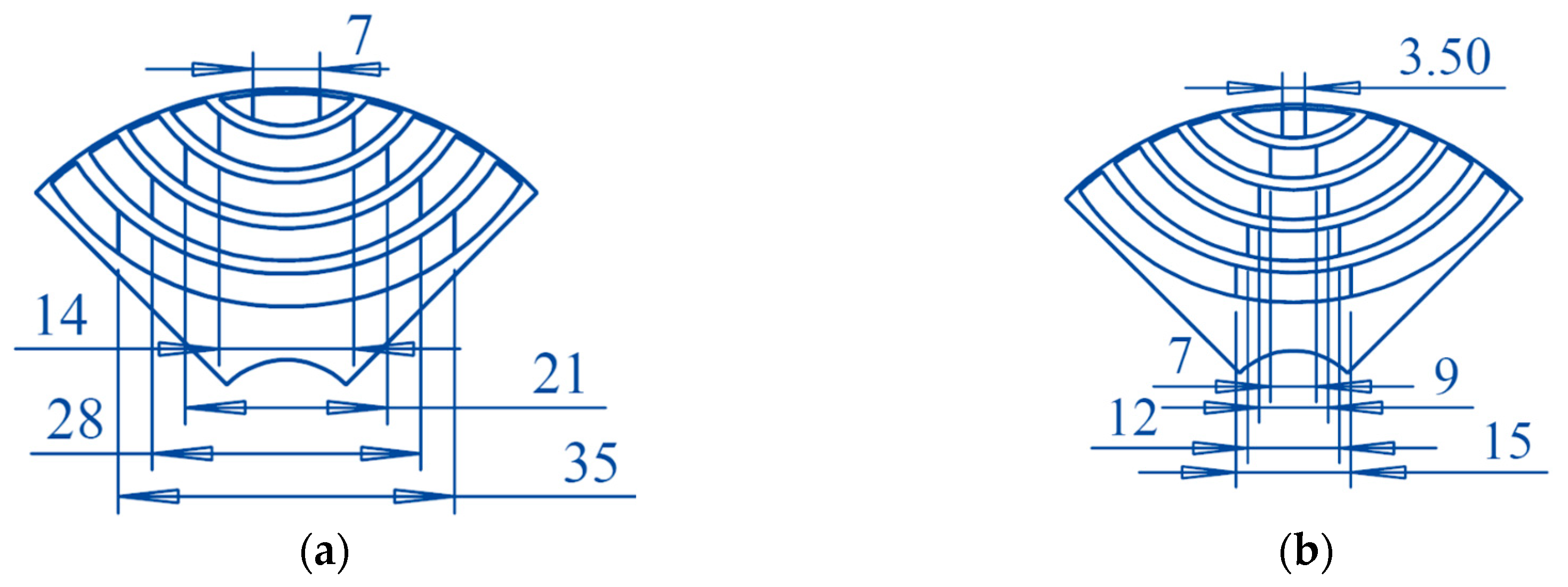
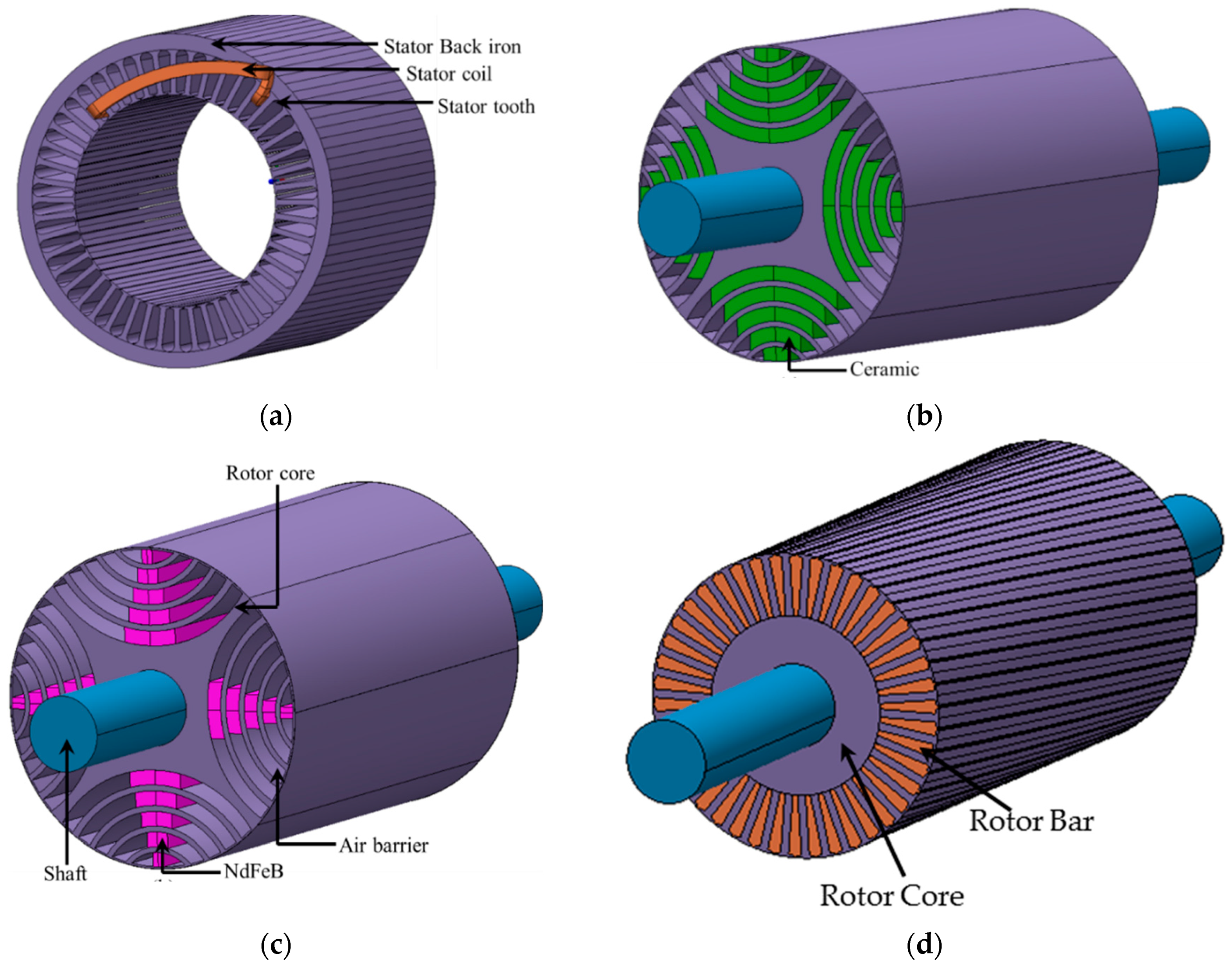
3.1. Permanent Magnet Synchronous Reluctance Generator

The design procedure of PMA-SynRG consists of following steps:
  • The barrier number, size, position and shape are optimized for required output voltage and good saliency ratio.
  • The magnets are designed and placed to meet the PM flux linkage required for this application.
The count of flux barrier is optimized as five per pole. Increasing the barrier count greater than five does not have key variations in the saliency ratio related to stator slots and barrier geometries [19,20]. Further increasing the number of flux barrier greater than five imposes mechanical problems with respect to rotor geometry [21].
The rotor topology and the polarization of the magnets are presented in Figure 2. The rotor design (the PM dimensions) was modelled with the help of numerical analysis with five flux barrier per pole to increase saliency and reduce cogging torque.

3.2. Induction Generator

The presence of residual flux in the rotor core and the excitation capacitance self-excites IG, causing the stator voltage to build up. The excitation capacitance is calculated as follows:
Apparent power
P A = P cos   θ
Reactive power
P R = P A 2 P 2
From the reactive power, the necessary capacitive current (Icap), reactance (Xcap) and capacitance (C) of the capacitor are calculated from the given equations:
I C a p = P R V t e r m
X C a p = V t e r m I c a p
C = 1 2   π   f   X c a p
From the machine parameters, Equations (1)–(5), the capacitor value is fixed as 400 µF, 400 V. The rotor of IG, designed with the help of finite elements, is displayed in Figure 3.

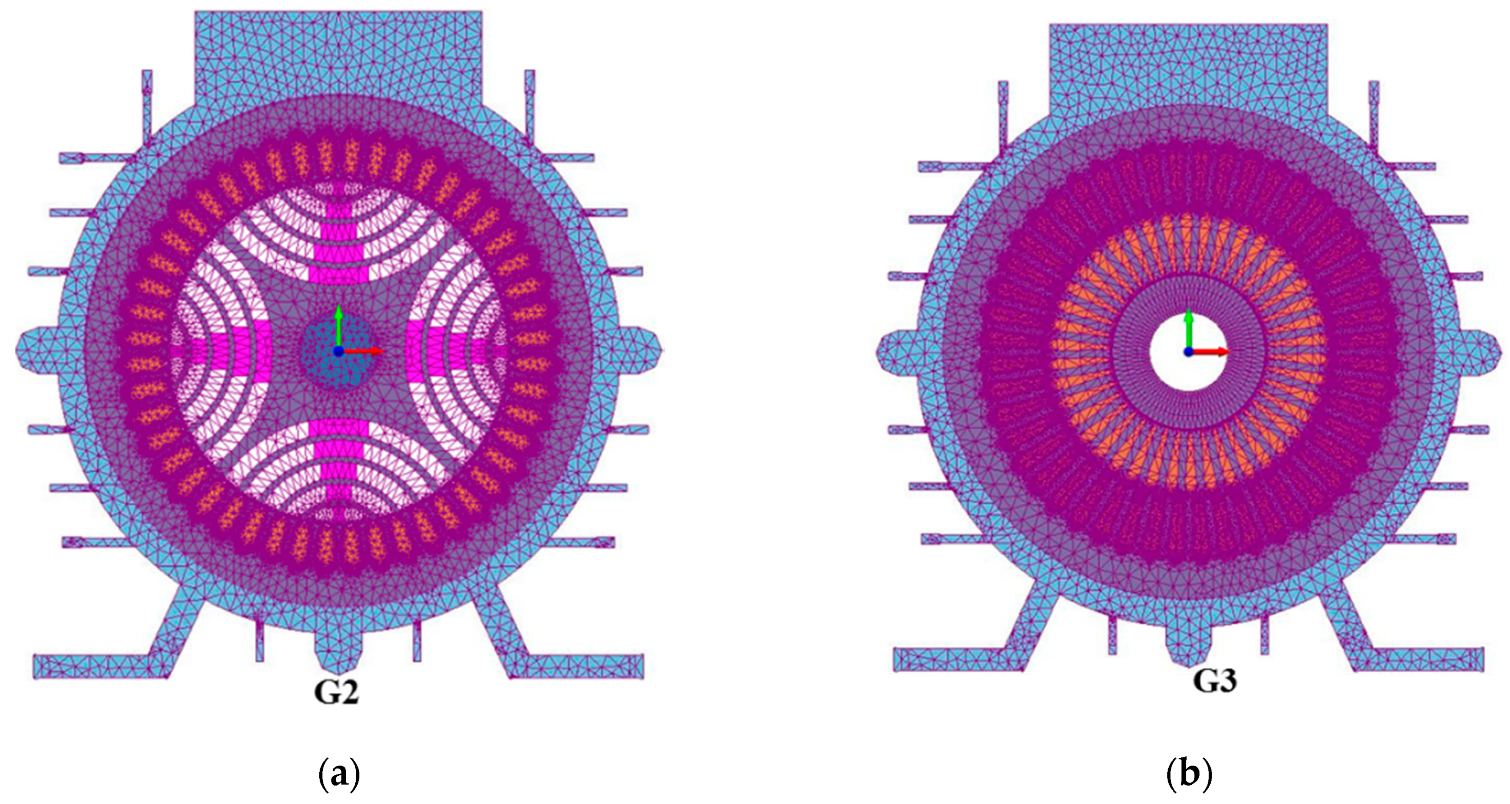
4. Finite Element Analysis

A single phase PMA-SynRG and IG were designed for portable applications with a 48 slot stator. The rotor with ferrite (G1), NdFeB magnet (G2) and IG (G3) is presented in Figure 4. The stator with distributed windings was used for all three machine configurations, i.e., the same dimensions (except stack length). The design requirement of the machine is tabulated in Table 2. The output characteristics of the modelled generator connected to a resistive load were simulated by MagNet software. During the pre-processing stage, the analytical design was modelled. Subsequently, the material was assigned and the triangular mesh region created. The mesh was denser in the air gap region so as to accurately analyze the effects of air gap flux density (Refer to Figure 5). The meshed design of G1 was 29,304 nodes and 58,306 elements, whereas for G2 it was 27,204 nodes and 54,370 elements. Furthermore, the G3 has 33,086 nodes and 66,134 elements. Transient with motion analysis was performed with designed source circuit.

4.1. Flux Distribution

In PMA-SynRG, the direct and quadrature axes flux linkages can be represented as
d-axis flux linkage:
λ d = L d i d
q-axis flux linkage:
λ q = L q i q Λ p m
where Λ p m represents the PM flux linkage, L d and L q are d- and q-axes inductances, respectively. Similarly i d and i q are corresponding d- and q-axes currents.
In Figure 6, the magnetic flux density for G1, G2, and G3 are presented, where G3 has a maximum flux density of 1.36 Wb/m2.

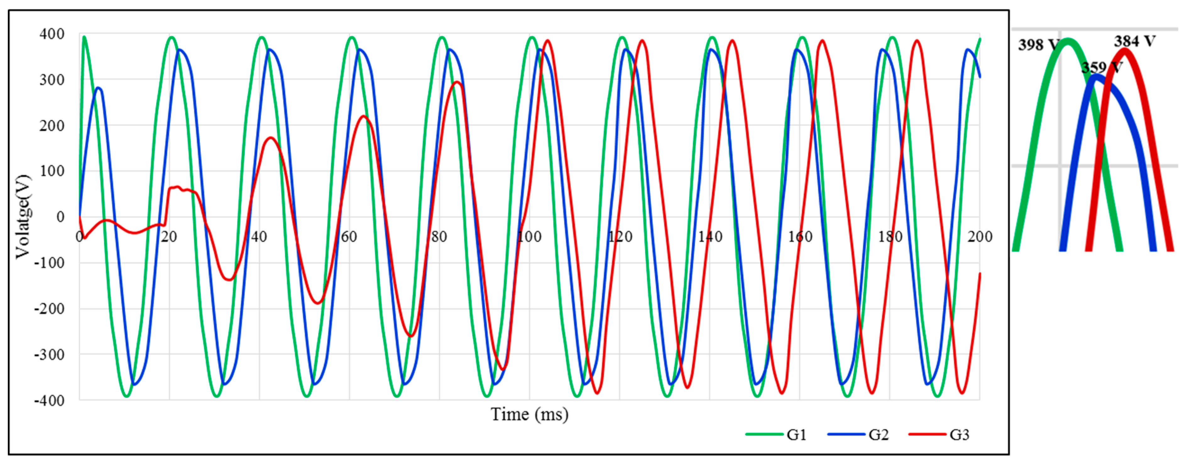
4.2. Output Voltage Waveforms

The aim of a generator design is to generate stator voltage which almost looks like a sinusoidal waveform with a minimal harmonic content, which minimizes the losses in the generator. In Figure 7, stator-winding peak–peak voltage under resistive load condition for G1, G2, and G3 is presented. During no-load operation, the peak–peak voltage of 359 V is generated in G2, whereas it is 384 V in G3, respectively.
At full load condition, the voltage generated in G2 was 326 V peak–peak voltages, as shown in Figure 8, while in G1 it was 324 V. Moreover, transients voltages from the stator windings at full load condition were obtained with the excitation capacitor in G3, where the excitation capacitor was Ce = 400 μF. The voltage values confirm that the voltage regulation of G2 was better when compared with G1 and G3. Furthermore, the waveforms show that while using ferrite magnet the harmonics were higher compared to G2 topology.

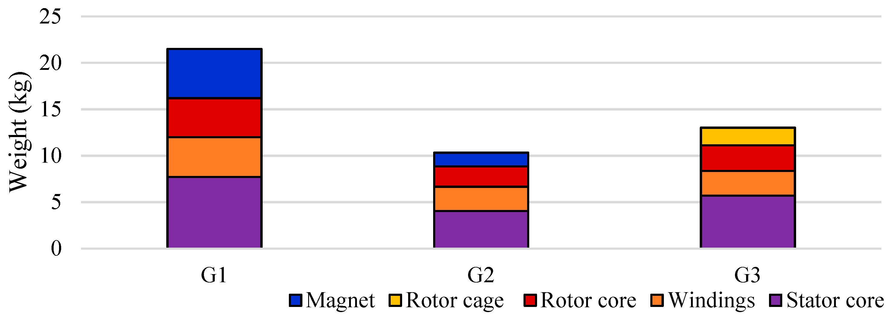
4.3. Weight of the Generators

As stated above, G2 has exactly the same structure as G1 and G3 except for the stack length which is 30.5% and 15.2% higher than G2. Accordingly, the weight of the active material and core material are not similar. The amount of PM used in G1 to achieve the required output was 72.2% higher than the G2 configuration. The reason behind this is NdFeB, which produces energy that is eleven times higher than that of the ferrite (about 367 kJ/m3 versus 32.9 kJ/m3) [22], resulting in the stack length of the machine to increase in order to achieve the required power, increasing the overall weight of G1. The overall weight comparison of each component of G1, G2, and G3 are displayed in Figure 9. These results confirm that the ferrite rotor (G1) was not a feasible machine for military applications, where weight plays a major role. The overall weight of G1 was 39.44% and 52% higher than G3 and G2, respectively. The further mechanical comparison was analyzed for G2 and G3 rotor configurations.

5. Mechanical Analysis

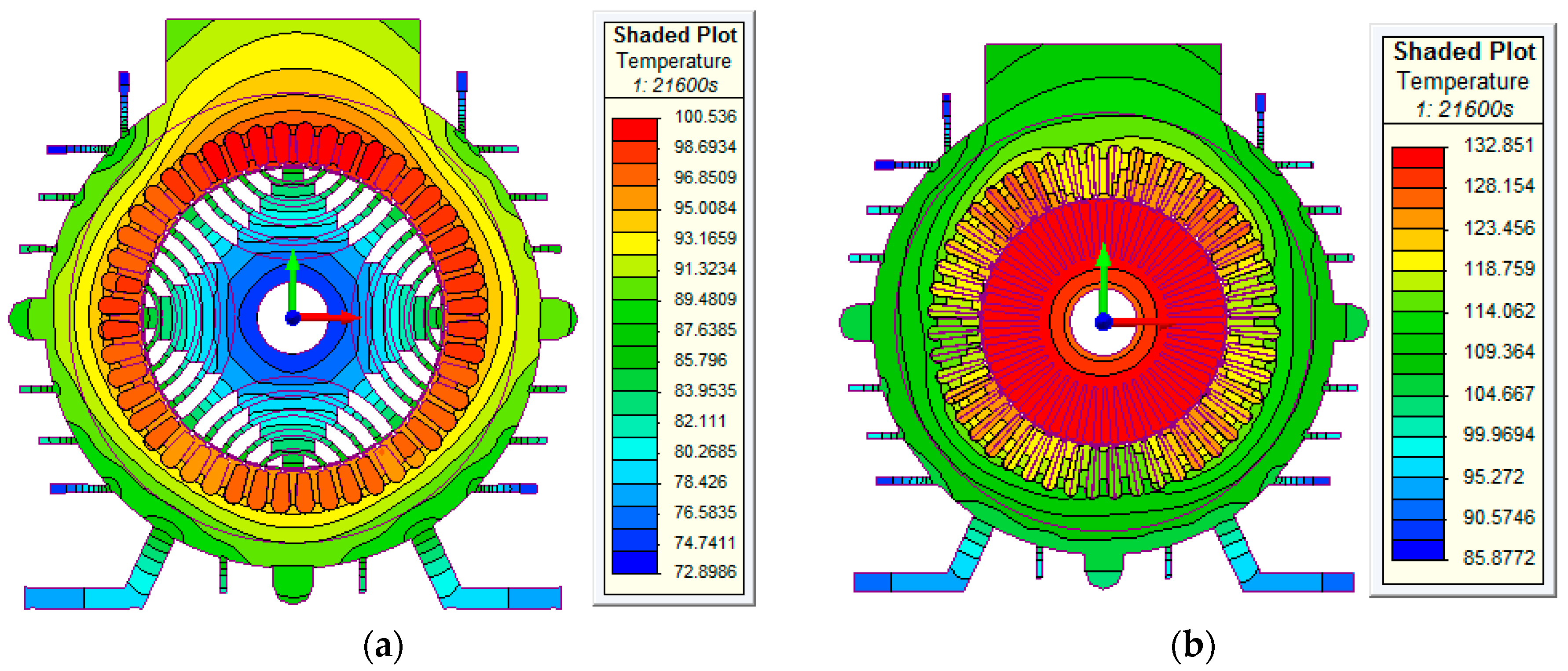
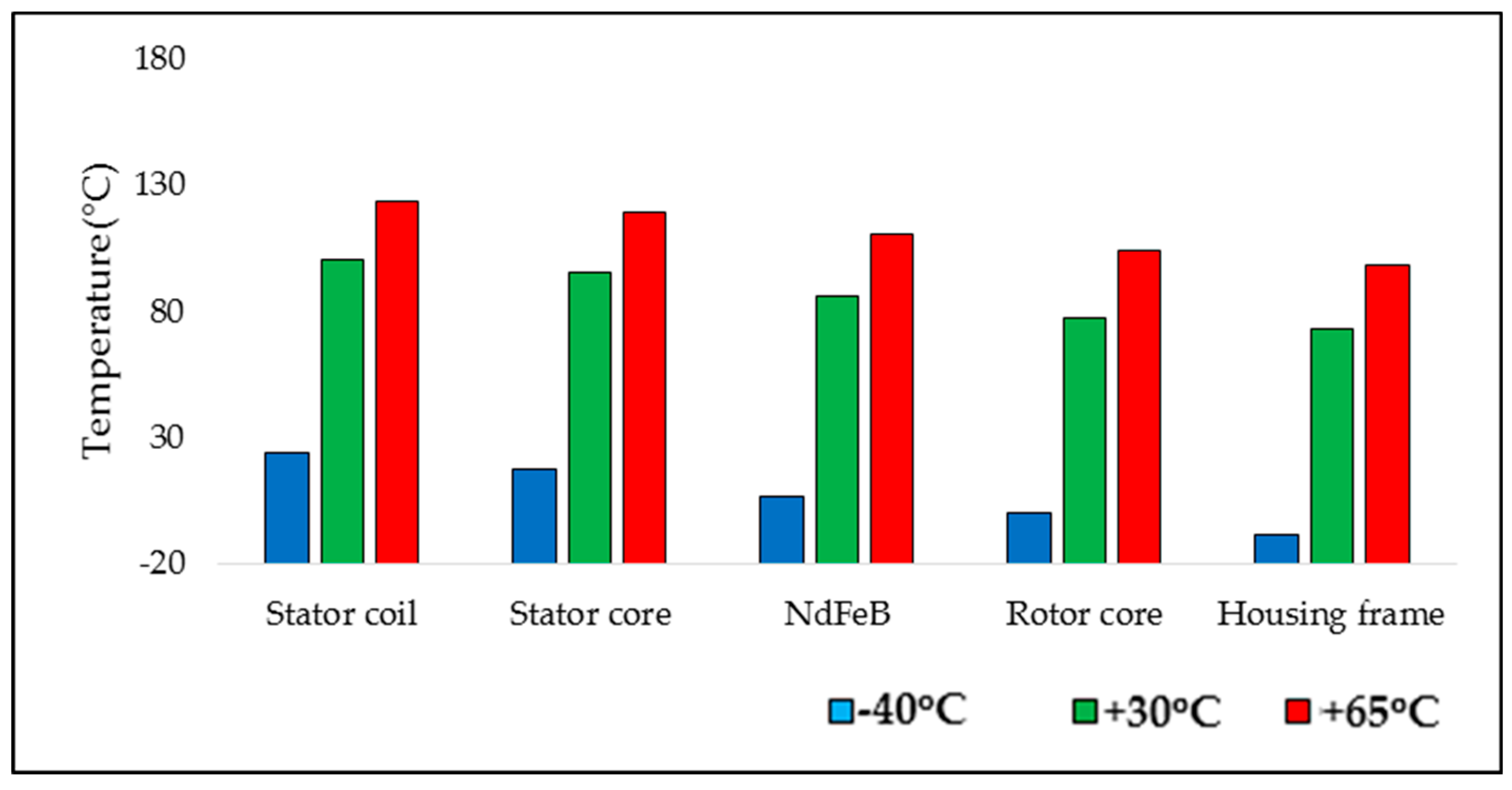
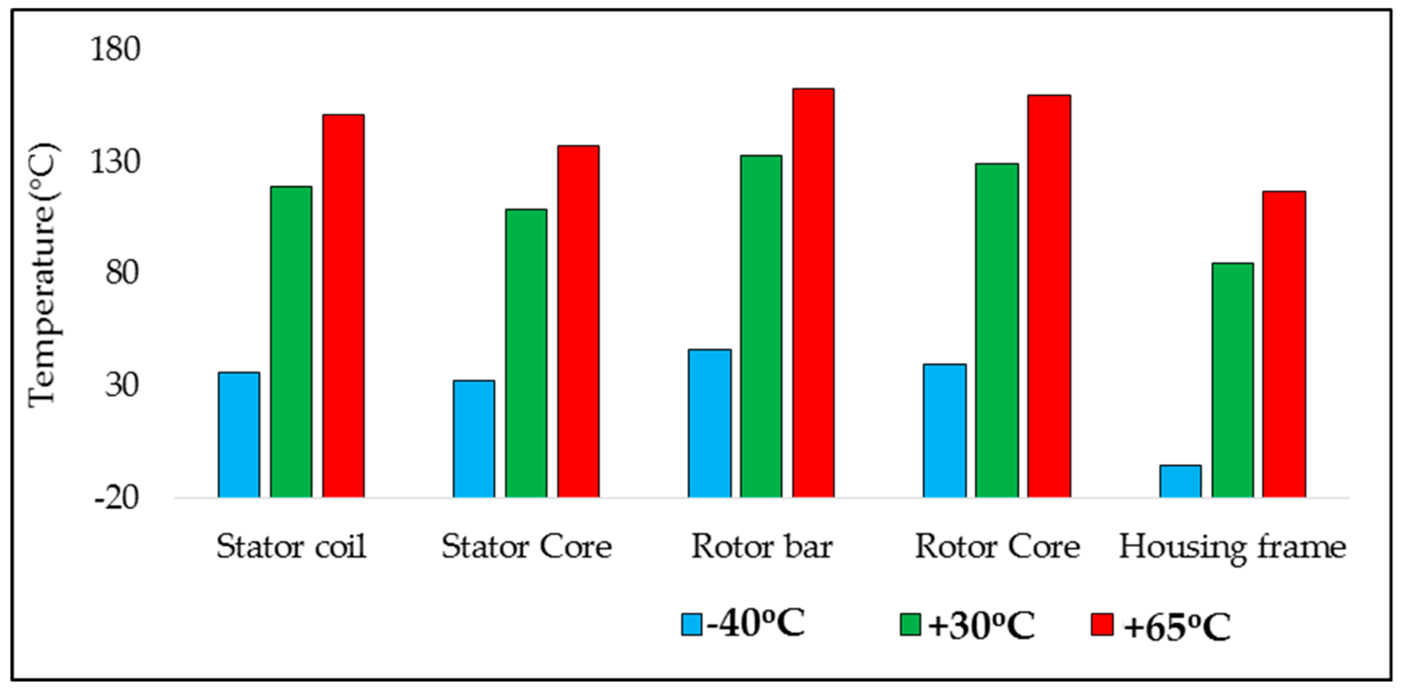
5.1. Transient Thermal Analysis

In a hollow cylinder containing a heat source, conductive heat transfer with various boundary conditions was obtained from the Fourier law in the cylindrical coordinate as [23]
1 r r ( k r T r ) + 1 r 2 θ ( k T θ ) + Z ( k T Z ) + q = ρ c d T d t
Thermal analysis was carried out for 5 kW PM-SynRG with NdFeB (G2) and IG (G3). This FEA analysis dealt primarily with heat conduction through the generator components. The quantity of heat transmitted from the excited phase to surrounding regions primarily depended upon convection heat transfer coefficients, h. The value of ‘h’ depends on thermal conductivity, specific heat, fluid dynamic viscosity and other properties of the coolant. The set of dimensionless numbers used in the calculation of convection heat transfer coefficients are given in Table 3.
In the Appendix A, Table A2 depicts the thermal properties for different materials used in G2 and G3 for thermal analysis. For the mesh region in Figure 10, G2 has 63,039 nodes and 121,776 elements, whereas for G3 has 69,739 nodes and 134,720 elements.
From the electromagnetic analysis, the core loss and copper loss of G2 and G3 are calculated and tabulated for full load condition in Table 4. These losses are incorporated as input in thermal analysis to estimate the maximum temperature rise in G2 and G3.
The thermal analysis was performed for ambient temperatures of +30 °C. The transient thermal analysis was performed for a duration of 6 h. The estimated temperature distribution in the generator for full load (100% load) condition is presented in Figure 11.
For full load in G2, it was noted that the temperature ranged from 94 °C to 100 °C, with the maximum temperature occurring on the stator winding. For full load in G3, it was noted that the temperature ranged from 118 °C to 132 °C, with the maximum temperature occurring on the rotor bar.
The temperature distribution of G2 and G3 for the various ambient conditions (−40 °C, +30 °C +65 °C), is shown in Figure 12 and Figure 13. At −40 °C, temperature in housing frame is −5.12 °C and −8.56 °C for G3 and G2, respectively.

5.2. Torque Waveform in Generating Mode

Figure 14 displays the FEA evaluated electromagnetic torque during generating operation. Furthermore, it was observed that the peak to peak torque ripple of G2 was 9% less than G3. The barrier count per pole, size, and placement of PM were the key parameters which influenced the ripple content in the developed torque [20]. The torque ripple was the main reason for the noise level of the machine. In the next section, the acoustic analysis was performed for both generators.

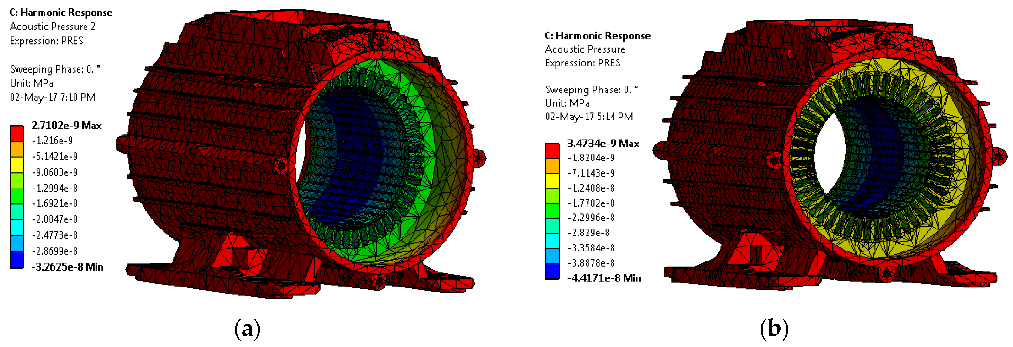
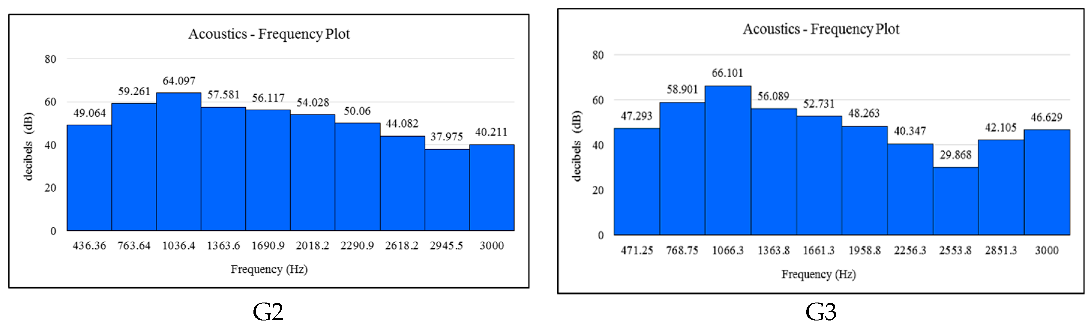
5.3. Acoustic Analysis

Sound pressure and sound power were the two constraints to compute the local and global acoustic effects [25,26].
In Figure 15, acoustics versus frequency plot measured by decibels are presented for G2 and G3. The maximum noise level was identified from the acoustics versus frequency plot. For (G2) frequency 1036.4 Hz, it was noted that the acoustic pressure of the stator core ranged from −3 × 10⁻⁸ MPa to 2.8 × 10⁻⁹ MPa (refer to Figure 16a). For (G3) frequency 1066.3 Hz, it was noted that the acoustic pressure of the stator core ranged from −4 × 10⁻⁹ MPa to 3 × 10⁻⁹ MPa (refer to Figure 16b). The overall machine performances of G2 and G3 are presented in Table 5.

6. Cost Estimation

The detailed cost estimation of various components of a 5 kW portable generator for military applications is tabulated in Table 6 (also refer Table A3).

7. Conclusions

This paper investigated the electro-magnetic design analysis of PMA-SynRG with a ferrite rotor (G1), NdFeB rotor (G2), and induction generator (G3). Furthermore, the machines were examined in all aspects, including thermal and acoustic analysis.

From the Analysis

Voltage regulation in the G2 rotor was 8.77% less compared to G3.
The magnet weight used in G1 was 72.2% higher than G2.
The overall weight of G2 was 20.7% and 52% less than G3 and G1, respectively.
At rated load, both generators were within the thermal limit for ambient conditions prescribed by the military requirements.
The noise level of G2 and G3 was 64 dB and 66 dB, respectively, which is within the range of military standards.
Based on the results, it is clearly evident that both, the PMA-SynRG with NdFeB rotor (G2) and IG are a good choice for military applications (as per military standards), whereas PMA-SynRG with NdFeB (G2) are more suitable within the aspects of power, weight, size, thermal and noise. Likewise, the induction generator is appropriate in the features of power, thermal noise and overall cost. Furthermore, the prototype fabrication process of the machine is under progress.

Author Contributions

All authors involved in the research activities in equally and distributed the technical expertise and to develop the outcome for the presented full research article.

Funding

This research received no external funding.

Acknowledgments

The authors would be thankful for the financial and technical assistance provided by the Combat Vehicles Research and Development Establishment (CVRDE), Defence Research and Development Organisation (DRDO) Avadi, Chennai, India (CVRDE/17CR0002/VED/16-17/LP).

Conflicts of Interest

The authors declare no conflict of interest.

Appendix A

Table A1. Permanent magnet characteristics [22].
MagnetCharacteristicUnitValue
FerriteResidual induction Br at 20CTesla0.42
Energy Product at 20CkJ/m332.9
Mass densitykg/m34900
Max. Working Temperature°C300
Curie Temperature°C450
NdFeBCharacteristicUnitValue
Residual induction Br at 20CTesla1.39
Energy Product at 20CkJ/m3367.4
Mass densitykg/m37500
Max. Working Temperature°C230
Curie Temperature°C310
Table A2. Thermal properties of the material used.
MaterialDensity
(Kg/m3)
Specific Heat
(J/KgC)
Thermal Conductivity
(W/mC)
M36-29 Gauge770049025
Copper8954383.1386
Nomex 410140013000.14
Cast Iron727248636.3
N52 (NdFeB)75004607.6

Appendix B

Table A3. References for cost analysis.
S.
No
MaterialGradePrice Reference LinkCost/kg (Rounded Off)
Min.Max.
1Non-Oriented AISI Silicon SteelM-36 29 Gahttps://www.indiamart.com/proddetail/crgo-electrical-steel-17427063588.html
https://www.indiamart.com/proddetail/crgo-transformers-sheet-17382640691.html
https://www.indiamart.com/proddetail/crgo-steel-sheet-coil-20408399155.html
80130
2NdFeB N52https://www.indiamart.com/proddetail/rare-earth-magnet-rod-5698105812.html
https://www.indiamart.com/proddetail/rare-earth-magnets-10573830273.html
1000012000
3Copper coil AWG-15https://www.indiamart.com/proddetail/copper-winding-coil-15789944088.html
https://www.indiamart.com/proddetail/copper-bare-wire-10182933762.html
https://www.indiamart.com/proddetail/winding-wire-17856803030.html
500620
AWG-16
4Copper bar https://www.indiamart.com/proddetail/phosphorised-copper-bars-12436604612.html
https://www.indiamart.com/proddetail/copper-bars-8021904930.html
https://www.indiamart.com/proddetail/ec-grade-copper-bars-18801056473.html
500550
5Capacitor 200 uF/440 Vhttps://www.mouser.in/Passive-Components/Capacitors/Film-Capacitors/_/N-5g7r?P=1z0wqt2Z1ywtais5600
(1 count)
7460
(1 count)
6Nomex InsulationClass Fhttps://www.indiamart.com/proddetail/nomex-insulation-paper-class-f-19444242012.html
https://www.indiamart.com/proddetail/f-class-h-class-insulation-paper-10121409648.html
7501500
Class Hhttps://www.indiamart.com/proddetail/nomex-insulation-paper-class-h-dupont-19444400255.html
https://www.indiamart.com/proddetail/h-class-insulation-paper-8938225933.html
25004000
7Grey cast ironGrade 350https://www.indiamart.com/proddetail/grey-iron-casting-20401746330.html
https://www.indiamart.com/proddetail/grey-iron-casting-20570455262.html
5080
8Journal bearingBearing Steelhttps://www.indiamart.com/proddetail/6004-zz-nsk-ball-bearings-20442772655.html
http://www.easysparepart.com/NBC-Ball-Bearing-6004ZZ
100160
9Fasteners
SS 304
(M12x20)
IS 1363/DIN 933/BS 1083https://www.pmmetal.com/special-steel-fasteners/stainless-steel-fasteners/stainless-steel-fasteners/
https://www.swiftindustrial.in/downloads/HighTensileFastners.pdf
25
(1 count)
30
(1 count)
10Fasteners
SS 304
(M16x30)
55
(1 count)
65
(1 count)

References

  1. Atlascopco. Available online: https://www.atlascopco.com/content/dam/atlas-copco/construction-technique/portable energy/documents/2_generators/spain/portable-generators/portable-generators-leaflet-english.pdf (accessed on 13 September 2018).
  2. Championpowerequipment. 2017. Available online: https://y79961nbs4u2hvbnwronx9zx-wpengine.netdna-ssl.com/wp-content/uploads/2017/09/100490-om-english.pdf (accessed on 9 August 2018).
  3. Misron, N.; Rizuan, S.; Vaithilingam, A.; Mailah, N.F.; Tsuyoshi, H.; Hiroaki, Y.; Yoshihito, S. Performance Improvement of a Portable Electric Generator Using an Optimized Bio-Fuel Ratio in a Single Cylinder Two-Stroke Engine. Energies 2011, 4, 1937–1949. [Google Scholar] [CrossRef]
  4. Matthew, K.S. Electromagnetic Generators for Portable Power Applications. Ph.D. Thesis, University of California, Berkeley, CA, USA, 2005. [Google Scholar]
  5. Home Generators Basics. 2008. Available online: https://www.smps.us/home-generators.html (accessed on 13 September 2018).
  6. Norhisam, M.; Syafiq, M.; Aris, I.; Abdul Razak, J. Design and analysis of a single phase slot-less permanent magnet generator. In Proceedings of the International Conference on Power and Energy, Johor Baharu, Malaysia, 1–3 December 2008; pp. 1082–1085. [Google Scholar]
  7. Stegen, K.S. Heavy rare earths, permanent magnets, and renewable energies: An imminent crisis. Energy Policy 2015, 79, 1–8. [Google Scholar] [CrossRef]
  8. Alkane Resources Ltd. Available online: http://www.alkane.com.au/products/rare-earths-overview/ (accessed on 13 March 2018).
  9. Constantinides, S. The Demand for Rare Earth Materials in Permanent Magnets. In Proceedings of the 51st annual Conference on Metullurgists, Niagara Falls, NY, USA, 30 September–3 October 2012; pp. 1–58. [Google Scholar]
  10. Guyonnet, D.; Lefebvre, G.; Menad, N. Guyonnet et al. Rare Earth Elements and High Tech Products. Available online: https://www.cec4europe.eu/wp-content/uploads/2018/09/Chapter_3_3_Guyonnet_et_al_Rare_earth_elements_and_high_tech_products.pdf (accessed on 3 January 2019).
  11. Roshanfekr, P.; Lundmark, S.; Thiringer, T.; Alatalo, M. A synchronous reluctance generator for a Wind Application-compared with an interior mounted permanent magnet synchronous generator. In Proceedings of the International Conference on Power Electronics, Machines and Drives (PEMD), Manchester, UK, 8–10 April 2014; pp. 1–5. [Google Scholar]
  12. Hsiao, C.-Y.; Yeh, S.-N.; Hwang, J.-C. Design of high performance permanent-magnet synchronous wind generators. Energies 2014, 7, 7105–7124. [Google Scholar] [CrossRef]
  13. Vartanian, R.; Deshpande, Y.; Toliyat, H.A. Performance analysis of a rare earth magnet based NEMA frame Permanent Magnet assisted Synchronous Reluctance Machine with different magnet type and quantity. In Proceedings of the International Conference on Electric Machines & Drives (IEMDC), Chicago, IL, USA, 12–15 May 2013; pp. 476–483. [Google Scholar]
  14. Tefera, K.; Tripathy, P.; Adda, R. Electromagnetic and mechanical stress analysis of wind-driven synchronous reluctance generator. CES Trans. Electr. Mach. Syst. 2019, 3, 107–114. [Google Scholar] [CrossRef]
  15. Alnajjar, M.; Gerling, D. Medium-speed synchronous reluctance generator as efficient, reliable and low-cost solution for power generation in modern wind turbines. In Proceedings of the International Symposium on Power Electronics, Electrical Drives, Automation and Motion, Amalfi, Italy, 20–22 June 2018; pp. 1233–1238. [Google Scholar]
  16. Yamada, A.; Miki, I. Novel Rotor Structure of Permanent Magnet Synchronous Motor with Rare Earth and Ferrite Magnets. In Proceedings of the International Symposium on Power Electronics, Electrical Drives, Automation and Motion, Ischia, Italy, 18–20 June 2014; pp. 1–5. [Google Scholar]
  17. Selmi, M.; Rehaoulia, H. A simple method for the steady state performances of self-excited induction generators. In Proceedings of the International Conference on Electrical Engineering and Software Applications, Hammamet, Tunisia, 21–23 March 2013; pp. 1–4. [Google Scholar]
  18. Chan, T.F. Analysis of a single-phase self-excited induction generator. Electr. Mach. Power Syst. 1995, 23, 149–162. [Google Scholar] [CrossRef]
  19. Reza, R.M. Synchronous Reluctance Machine (SynRM) Design. Master’s Thesis, Royal Institute of Technology Stockholm, Stockholm, Sweden, 2007. [Google Scholar]
  20. Ashkezari, J.D.; Khajeroshanaee, H.; Niasati, M. Optimum design and operation analysis of permanent magnet-assisted synchronous reluctance motor. Turk. J. Electr. Eng. Comput. Sci. 2017, 7, 7105–7124. [Google Scholar]
  21. Boroujeni, S.T.; Haghparast, M.; Bianchi, N. Optimization of flux barriers of line-start synchronous reluctance motors for transient- and steady-state operation. Electr. Power Compon. Syst. 2015, 43, 3–17. [Google Scholar] [CrossRef]
  22. Massimo, B.; Nicola, B. Interior PM machines using ferrite to replace rare-earth surface PM machines. IEE Proc. Electr. Power Appl. 2014, 50, 979–984. [Google Scholar]
  23. Pavan, A.; Sathyanarayanan, N.; Rajeshkumar, R.; Lenin, N.C.; Sivakumar, R. Thermal analysis of a 3 phase, 550 w switched reluctance machine. Int. J. Appl. Eng. Res. 2015, 10, 86–90. [Google Scholar]
  24. Staton, D.A.; Cavagnino, A. Convection heat transfer and flow calculations suitable for electric machines thermal models. IEEE Trans. Ind. Electron. 2008, 55, 3509–3516. [Google Scholar] [CrossRef]
  25. Tong, W. Mechanical Design of Electric Motors; CRC Press: London, UK, 2014; p. 481. [Google Scholar]
  26. Timar, P.L. Noise and Vibration of Electrical Machines; Elsevier Science Ltd.: Amsterdam, The Netherlands, 1989; p. 355. [Google Scholar]
Figure 1. Dissembled view of portable generator.
Energies 12 02285 g001
Figure 2. Geometrical dimensions of PMA-SynRG, (a) ferrite (G1), (b) NdFeB (G2).
Energies 12 02285 g002
Figure 3. Geometrical dimensions of induction generator. (a) Rotor core, (b) Rotor bar.
Energies 12 02285 g003
Figure 4. SynRG with: (a) stator, (b) ferrite rotor, (G1), (c) NdFeB rotor (G2), (d) IG (G3).
Energies 12 02285 g004
Figure 5. Mesh generation of G1, G2, and G3.
Energies 12 02285 g005
Figure 6. Flux density plot for G1, G2, and G3.
Energies 12 02285 g006
Figure 7. No-load voltage of G1, G2, and G3.
Energies 12 02285 g007
Figure 8. Full load voltage of G1, G2, and G3.
Energies 12 02285 g008
Figure 9. Weight comparison of G1, G2, and G3.
Energies 12 02285 g009
Figure 10. Mesh region with outer frame for (a) G2 and (b) G3.
Energies 12 02285 g010
Figure 11. Temperature distribution for (a) G2 and (b) G3 (+30 °C ambient temperature). * All units are in °C.
Energies 12 02285 g011
Figure 12. Temperature distribution of G2 for various ambient conditions (−40 °C, +30 °C, +65 °C).
Energies 12 02285 g012
Figure 13. Temperature distribution of G3 for various ambient conditions (−40 °C, +30 °C, +65 °C).
Energies 12 02285 g013
Figure 14. Electromagnetic torque during generating mode for G2 and G3 (operating at rated load).
Energies 12 02285 g014
Figure 15. Acoustic versus frequency plot.
Energies 12 02285 g015
Figure 16. Acoustic pressure level for (a) G2 and (b) G3.
Energies 12 02285 g016
Table 1. As per military standards.
CharacteristicValue
5 kW
Weight, (dry)750 lbs. (340.2 Kg)
Weight, wet, 80% fueled796 lbs. (361.1 Kg)
Noise68 dBA
Dimensions45 × 32 × 36 in (1.143 × 0.813 × 0.914 m)
Thermal ambient conditions−42 °C to + 65 °C
Table 2. Design requirements.
ParametersUnitValue
Output powerkW5
Speedrpm1500
VoltageV230
FrequencyHz50
No. of phase-1 ϕ
No of poles-4
Outer stator diametermm125
Inner stator diameter-85
Magnet thicknessmm5
Load resistanceΩ10.6
Stack lengthmmG1G2G3
1187591
Table 3. Dimensionless parameters to calculate heat transfer coefficient [24].
Dimensionless NumberEquationNomenclature
Reynold’s number Re = D 2 ω υ D—Diameter of the stator up to the stator pole arc (m)
ω —Angular velocity = 2 ∏ N/60 (rad/s)
N—Speed of the motor (rpm)
υ —Kinematic viscosity (m2/s)
β—Coefficient of cubical expansion of fluid (K−1)
g—Gravitational force of attraction (m/s2)
θ—Temperature difference between surface and fluid (K)
ρ —Fluid density (kg/m3)
L—Characteristic length of the surface (m)
µ—Fluid dynamic viscosity (Kg/m s)
c—Specific heat capacity of fluid (J/Kg K)
λ—Thermal conductivity of fluid (W/m K)
Grashof number G r = β g θ ρ 2 L 3 μ 2
Prandtl number Pr = c μ λ
Nusselt Number h = N u ( λ ) L  
Table 4. Electromagnetic losses.
ComponentsHeat Loss
G2G3
Copper loss491833
Core loss3533
Table 5. Overall performance comparison of G1, G2, and G3 topologies.
ParameterG1G2G3Remarks
No load induced EMF (V)281253.8263
  • The voltage regulation of G1 is 3.73 % and 12.52% higher than G3 and G2.
  • G2 has 8.7% reduced voltage regulation than G3.
  • G2 has a 21.57% higher power/weight ratio than G3.
  • G3 has 5.7% less efficient tan G2.
  • Noise level of G2 is 3% lesser than G3.
Full load voltage (V)229.1230.5228.7
Full load current (A)21.922.222.17
Output power (kW)5.025.125.07
Total losses (W)941613995
%Efficiency84.289.383.6
%Voltage regulation22.6510.1318.9
kW/kg0.2330.4960.389
Maximum winding temperature (°C)-NE-100 °C132 °C
Noise level (dB)-NE-6466
* NE—not evaluated
Table 6. Overall cost analysis of PMA-SynRG and IG.
S.
No
MaterialGradePrice/kg (approx.)Part NumberQuantity (kg)Cost (INR)
(max.)
G2G3G2G3
1Non-Oriented AISI Silicon SteelM-36 29 Ga80 to 130-7109101300
2NdFeB N5210000 to 12000-1.5nil18000-NA-
3Copper coil AWG-15500 to 620-nil3-NA-1860
AWG-16500 to 620-2.5-NA-1550-NA-
4Copper bar-500 to 550-nil2.5-NA-1375
5Capacitor 200 uF/440 V5600 to 7460871-B32361B2207J50nil2 (count)-NA-14920
6Nomex InsulationClass F750 to 1500-2nil3000-NA-
Class H2500 to 4000-nil2-NA-8000
7Grey cast ironGrade 35050 to 80-Pleae810640800
8Journal bearingBearing Steel100 to 1606004
6004 ZZ
2
(count)
2
(count)
320320
9Fasteners
SS 304
IS 1363/DIN 933/BS 108325 to 30M12x208
(count)
8
(count)
240240
10Fasteners
SS 304
IS 1363/DIN 933/BS 108355 to 65M16x304
(count)
4
(count)
260260
11Fabrication---nilnil4000030000
----Total (Approx.)22.52964920
(926 USD)
59075
(842 USD)

