Inhibition of Rejuvenation Liquid on Trees in XLPE Cables under Switching Impulse Voltages

School of Electrical Engineering and Information, Sichuan University, No. 24 Yihuan Road, Chengdu 610065, China
*
Author to whom correspondence should be addressed.
Energies 2019, 12(11), 2133; https://doi.org/10.3390/en12112133
Submission received: 7 May 2019
/
Revised: 26 May 2019
/
Accepted: 31 May 2019
/
Published: 4 June 2019
Abstract
:In this paper, the inhibitory effect of preinjected rejuvenation liquid on trees in cross-linked polyethylene (XLPE) cables was investigated. Experimental samples were prepared by inserting needles into XLPE samples, and many equally-spaced holes existed in the outer semiconductive layer. All cable samples were divided into two groups. One sample group was treated with rejuvenation liquid, while the other group was the control group. A tree accelerated aging system was used to obtain trees in the XLPE cable samples. During the aging experiment, an impulse voltage was applied to the samples repeatedly. The micromorphologies of the two groups were observed. Based on the micromorphologies, two parameters were determined: the initiation rate of electrical trees and the average length of trees. Furthermore, the electric field distribution was simulated to analyze the initiation of electrical trees. The results indicate that an electrical tree is much harder to initiate in the pretreated XLPE cables than in the untreated cables. This phenomenon is likely attributed to the dielectrophoretic forces in the pretreated cables. Moreover, rejuvenation liquid deposited in XLPE causes a substantial reduction in the Maxwell stress of molecular chains. Rejuvenation liquid inhibits electrical tree initiation and water tree growth to a great extent.
1. Introduction
Treeing degradation (both electrical trees and water trees) is considered the main cause of insulation breakdown in wet cross-linked polyethylene (XLPE) power cables [1]. For in-service cables, moisture can permeate insulation defects, possibly leading to water tree formation in energized cables under a driving electric field [2]. Moreover, in distribution grids, cables are commonly subjected to overvoltage generated from lightning strikes or circuit breaker switching. Electrical trees occur gradually, and XLPE eventually breaks down.
The tree growth mechanism in XLPE cables has long been a subject of research [3,4,5,6]. Researchers tried to detect the signals which are generated during the treeing process and studied the acoustic emission method and artificial neural networks in the detection of the electrical treeing [7,8]. Some novel approaches are also applied to develop a better understanding of electrical treeing [9]. Rejuvenation liquid injection technology is widely used to restore water tree-aged cables [10,11]. It is generally reported that the rejuvenation liquid can fill water tree voids and everyone agrees that rejuvenation will extend cable life by 20 to 30 years [12].
Water trees consist mainly of water-filled microvoids and interconnected channels, often called “strings of pearls” [13]. Water trees can easily convert to electrical trees, ultimately leading to insulation breakdown. An electrical tree generally originates in microscopic defects where the local electric field is high [14]. For water tree-degraded XLPE cables, injected rejuvenation liquid is effective in eliminating water trees [11]. Rejuvenation liquid injection significantly inhibits water tree initiation and growth in water tree-degraded cables [10]. Various kinds of rejuvenation liquid have been developed to improve this effect [15], and cable rejuvenation technology has advanced in several ways. Previous studies have focused mainly on the effect of rejuvenation liquid on water tree-aged cables. Few studies have investigated the effect of rejuvenation liquid injection on cable insulation recovery before aging or pretreatment.
In recent years, preinjected rejuvenation liquid has been proven to inhibit water tree growth before cable aging [16]. However, when switching impulse voltages are applied to cables, the inhibition mechanism of preinjected rejuvenation liquid on tree formation in XLPE is still unclear. Further investigation is required to determine whether preinjected rejuvenation liquid can inhibit electrical tree initiation. For this reason, new insights into the effect and mechanism of pretreatment on potential trees (including water trees and electrical trees) in XLPE cables would be helpful.
This study attempts to describe the inhibition mechanism of preinjected rejuvenation liquid on electrical tree initiation and water tree growth. Our main contributions can be listed as follows:
- (1)
- Comparing electrical tree initiation and water trees growth between two groups of cable samples after the cable-accelerated aging experiment.
- (2)
- Constructing a cable model that includes a water tree body by means of COMSOL software. Before simulation, the dielectrophoretic force of rejuvenation liquid particles is analyzed and considered by the model parameters. The electrical tree initiation mechanism is described by referring to the simulated electric field distribution of the cable.
- (3)
- Understanding the inhibition mechanism of water tree growth by analyzing the Maxwell stress of XLPE molecular chains. The local electric field at a water tree tip is referenced.
2. Experimental Steup
2.1. Sample Preparation
An 8.7/10 kV XLPE cable with a stranded aluminum conductor of 50 mm2 cross-sectional area was used in the experiment. That cable was cut into many 54-cm-long short specimens. A 2-cm-long outer semiconductive layer was stripped from both ends of the specimens. A metal needle, which has a tip radius of 2.5 ± 0.5 μm and a point angle of 10 ± 1°, was inserted vertically into the sample to a depth of 3 mm. The thickness of the semiconductive layer is 1 mm. The holes extend 2 mm in depth into the XLPE insulation layer after penetrating the semiconductive layer. Many equally spaced (3–5 mm) holes were made in the cable outer semiconductive layer.
Figure 1 shows the injection experimental setup. Adapters were installed at both ends of the cable sample. According to previous work [11,12,16], the rejuvenation liquid was injected through the adapters with a pressure of 0.2 MPa, and the gas pressure was maintained for 2–4 h to ensure that the rejuvenation liquid penetrated into the XLPE insulation layer. Then, the cable samples were kept steady for 3 days to ensure that the rejuvenation liquid diffused uniformly.
2.2. Experimental Setup
Figure 2 depicts the principle of the accelerated aging experiment, and Figure 3 depicts the test platform of the aging experiment. One group of pretreated cable samples was prepared after the rejuvenation liquid injection experiment, as shown in Figure 1. The copper shield was used to provide grounding during the tree aging process. To avoid exposing the XLPE insulation layer to moist air, the cable insulation layer was covered with a heat-shrinkable tube. A rectangular hole (60 mm × 25 mm) was formed at the centre of that tube surface. The 20 wt%-concentration NaCl solution (1.7 mol/L) filled the heat-shrinkable tube. In the accelerated cable aging experiment, a 7.5 kV AC voltage (frequency of 400 Hz) was applied to the cable samples. Furthermore, a switching impulse voltage (250/2500 μs) was applied to samples repeatedly.
3. Results and Discussion
This section presents and discusses the initiation rates of electrical trees and the growth of water trees in cable samples.
3.1. Microstructure Analysis
A microscopic analysis method was used to investigate the microstructures of trees in the untreated cable samples and the pretreated cable samples in this research. Cable samples after aging for 288 h were defined as samples at the first stage. All cable samples were cut into slices of 1-mm thickness around pinholes by means of a slicing machine. All slices were dyed in methylene blue solution for 24 h. Then, the slices were placed in a 90 °C incubator and heated for 30 min to ensure that the dye permeated the samples completely. A CCD camera was used to record tree images. Figure 4 depicts the microscope observation system. Finally, the microstructures of trees were observed and analyzed.
As the electrical tree inception in XLPE insulation is associated with many factors [17], the electrical trees occurred randomly in all slice samples. To analyze the electrical tree initiation and water tree growth clearly, all slices, including the untreated cable samples and the pretreated cable samples, were divided into two groups. Group A slices had no electrical trees, while group B slices had an electrical tree.
As shown in Figure 5, there is a hemisphere-shaped water tree at the tip of the pinhole in XLPE samples. The water tree length is marked. In Figure 5a, the water tree length in the untreated cable sample is 119 μm, while the water tree length in the pretreated cable sample is 92 μm. Figure 6 shows the tree microstructure of group B slices. Figure 6b shows that an electrical tree is completely covered by the water tree at the pinhole and that the water tree shape is similar to a hemisphere. This phenomenon can be ascribed to the design of the experiment. Before the experiment, we prepared the sample by inserting a metal needle into the cable. Pinholes existed in the insulation layer of the cable. After the preinjection experiment, an alternating electric field was applied to the cable sample. A switching impulse voltage (250/2500 μs) was applied to samples repeatedly in different aging periods (stages) of water tree aging. In the water tree aging experiment, the electric field at the needle tip distorted significantly, and water trees grew slowly. In the early stage of water tree aging, the density of water tree branches was relatively low, and the electric field strength at the needle tip can be higher than that at the water tree tip. The electric field strength at the needle tip can exceed the threshold value of the initiation electric field of the electrical tree (E0). For this reason, an electrical tree can be initiated from the needle tip [18]. Based on Figure 6, the tree length in the untreated cable sample is 309 μm, which is much longer than that in the pretreated cable sample. The preinjected rejuvenation liquid inhibited the water tree growth.
Cable samples after aging for 576 h were defined as samples at the last stage. Figure 7 shows the tree micromorphology of group A slices at the last stage. In an untreated cable sample, the water tree length is 279 μm. In Figure 7b, the water tree length in a pretreated cable sample is 230 μm. Comparing these results with Figure 4, water trees propagate with aging. The tree length in the untreated cable is similar to that in the pretreated cable. The inhibitory effect of preinjected rejuvenation liquid on water tree growth is weakened. This result may be ascribed to the reduction of residual rejuvenation liquid in the XLPE samples.
Figure 8 shows the tree micromorphology of group B slices at the last stage. Comparing the water tree region in Figure 8a,b, we can see that the water tree region in the pretreated cable sample is lighter in color than in the untreated cable sample. This result is because the rejuvenation liquid reserved in the pretreated cable sample reacts with water during subsequent tree aging. After the reaction, many inorganic particles are left in the samples, and the micropores in the water tree regions can be filled. As those particles are not easily dyed with methylene blue liquid, the color of the tree area is consequently much lighter.
3.2. Initiation Rate of Electrical Trees and Average Tree Length
Based on the experimental results, it is concluded that electrical trees initiate under impulse voltage. To investigate the inhibitory effect of preinjected rejuvenation liquid on electrical tree initiation, the initiation rates of electrical trees in two groups of cable samples were calculated. The average tree length was determined. The above two parameters can be calculated according to the following equations:
where P is the initiation rate of the electrical tree, L is the average tree length, m is the number of samples containing electrical trees, m0 is the total number of cable samples, and li is the average tree length of the ith sample.
Table 1 lists the statistical initiation rates of the electrical trees and the average tree length of the cable samples. The statistical assessment of L is shown in Figure 9.
According to the results, at the first stage, the initiation rate of electrical trees in the untreated cable samples is much higher than that in the pretreated samples. In the last stage, the initiation rates of electrical trees in the two kinds of samples are similar. The average tree length in the untreated samples is longer than that in the pretreated samples. It can be concluded that the preinjected rejuvenation liquid inhibits tree growth and that the inhibition weakens with cable aging.
3.3. SEM and EDS Analysis
To observe the microstructure of XLPE after preinjection of rejuvenation liquid, a sample around the pinhole in a pretreated cable was cut into slices. The microstructure of a slice was observed by means of scanning electron microscopy (SEM). The result is shown in Figure 10. It can be seen that some micron-sized granular matter appears in those images
To investigate its chemical elements, the micron granular matter was further analyzed by means of Energy Dispersive Spectroscopy (EDS). Figure 11 shows the EDS results. The granular matter consists mainly of carbon, titanium and some other elements. The rejuvenation liquid that was injected into the cable sample is the same as the liquid described in the literature [19]. The basic active components of the rejuvenation liquid are phenylmethyl-dimethoxy-silane (PMDMS) and titanium isopropoxide (TIPT). TIPT can not only be used as a catalyst but can also react directly with water to produce nano-TiO2 particles. The hydrolysis-condensation reaction of rejuvenation liquid with water occurred in the pretreated cables. After the reaction, the TiO2 gel remained in the water tree and filled the voids. As a result, it can be inferred that the granular matter observed in the pretreated cable sample is TiO2 particles generated from the hydrolysis reaction of TIPT.
3.4. Electrical Tree and Water Tree Modeling
By means of COMSOL software, a two-dimensional simulation model was constructed, as shown in Figure 12. Generally, an ellipsoid can be modeled as the main body of a water tree [20,21]. To understand the effect of the bifurcation structure on the external electric field distribution outside the water tree area, the water–tree model was constructed with an ellipsoid shape and peripheral branch tips. Figure 6b shows that many tiny tips were set at the edge of the water tree region. The electric field is very strong near the tips, which affects water tree growth. In this case, we were not concerned about the electric field distribution within the water tree area but the electric field distribution near the tips of the water tree. This model is closer to the actual situation than a single-ellipsoid model [20].
The model details and sizes are shown in Figure 12a,b. The needle electrode that was inserted into the experimental XLPE layer was 3 mm in length and 0.9 mm in diameter. A water tree and an electrical tree occurred below the pinhole. Figure 12b depicts the details of both trees. The electrical tree was represented by two branches, each of which was 2 μm in diameter and 50 μm in length. The water tree consisted of a series of micropores and channels, which resemble “string pearls”. In the model, the water tree main body was assumed to be spherical with a radius of 200 μm. To analyze the electric field at the tips of the water tree accurately, seven branch tips were set at the end of the water tree region. Each branch tip consisted of a channel and a void. The channel was 6 μm in length and 0.5 μm in width. The void was an ellipse, which was 8 μm in length along the major axis and 4 μm in length along the minor axis. The 20 wt%-concentration NaCl solution was considered to be injected into the insulation. In Figure 12, point M denotes the needle tip. Point N is 300 μm away from point M in the radial direction.
After the needle was inserted into the XLPE, the local electric field distorted. The electric field amplitude significantly affects water tree growth. In this situation, it is necessary to analyze the electric field distribution near the water tree tips.
Table 2 provides the model parameters. The XLPE relative permittivity ε1 is 2.3, and the conductivity γ1 is 1 × 10⁻¹⁷ S/m [22]. The relative dielectric constant in the water tree region was recorded as ε2 (2.7 ≤ε2 ≤ 16), and the conductivity was recorded as γ2 (1 × 10⁻¹¹–1 × 10⁻⁷ S/m) [23]. Because the water tree channels may have some conductive ions, both the conductivity and relative dielectric constant of these channels should be between those of the water and XLPE. As a result, we assumed the conductivity and relative dielectric constant for the water–tree body, as shown in Table 2. The 20%-concentration NaCl solution relative permittivity ε3 is 8.5 × 10⁷, and the conductivity γ3 is 2.0 S/m. The relative permittivity of polysiloxane, which is the reaction product of silicone liquid and water, is fixed at 2.8, and conductivity γ4 is 1 × 10⁻¹¹ S/m [24]. The semiconductive layer relative permittivity ε5 is 20, and the conductivity γ5 is 1 × 10⁻⁴ S/m. According to the experimental results shown in Figure 6b, an electrical tree grew from the needle tip. Water permeated into the XLPE and filled the channels of the electrical tree. Therefore, the electrical tree relative permittivity ε6 is set to 80, and the conductivity γ6 is set to 2.0 S/m.
3.5. Analysis of Electrical Tree Initiation
Electrical tree initiation is a complex phenomenon. It is recognized that the initiation of an electrical tree is due to the transmission of electrons from the electrode into dielectric insulation. Some electrons are captured by traps, and electrical trees finally occur. This phenomenon occurs when the local electric field exceeds the threshold value E0, which is suggested to be approximately 100 MV/m at ambient temperature [18]. Electrical tree initiation is closely associated with the electric field distribution in XLPE. The electric field distribution can be achieved based on the model in Figure 13. To investigate electrical tree initiation, the electrical tree and seven tiny tips of the water tree were disregarded in the model. Only the main body of the water tree was considered. An impulse voltage of 40 kV (250/2500 μs) was applied in the model.
To compare the initiation of electrical trees between untreated cables and pretreated cables, the electric field distributions of those two groups of cable samples were calculated. The relative dielectric constant affects the results significantly. For the pretreated samples, the actual relative dielectric constant in XLPE did not maintain a constant value. The residual rejuvenation liquid directly affected the local relative dielectric constant. The rejuvenation liquid diffused from the cable conductor to the insulation layer after injection. The diffusion efficiency was higher when the cross section of the cable conductor was larger. Figure 13a shows the rejuvenation liquid diffusion process.
The XLPE insulation layer consists of a crystalline region and an amorphous region. The preinjected rejuvenation liquid diffuses from the cable conductor into the insulation layer and is stored in the amorphous region. In the insulation layer, the concentration of rejuvenation liquid is high in the region next to the cable conductor [10]. An impulse voltage that was applied to the needle electrode distorted the local electric field at the needle tip. As the rejuvenation liquid molecules are polarized [25], the dielectrophoretic forces of the molecules caused them to centralize around the needle tip. Figure 13b shows the centralizing mechanism. By testing the relative dielectric constant of the rejuvenation liquid at ambient temperature, it is found that the value varies in the range of 4 to 6. Its relative dielectric constant is much higher than that of XLPE. For the reasons described above, the relative dielectric constant near the needle tip is larger than that at other regions of the insulation layer.
Due to the dielectrophoretic forces of rejuvenation liquid molecules in the pretreated cable, the relative dielectric constant was set to be an index increasing in the radial direction during calculation. The largest experimental relative dielectric constant of the insulation layer around the pinhole varied from 2.1 to 13. The local relative dielectric constant significantly affects the electric field distribution.
To investigate the relative dielectric constant effect on the electric field distribution, the highest relative dielectric constant in the XLPE at the needle tip is set to 3.3, 5.3, 7.3, and 9.3. Figure 14 shows the calculation results of the electric field distributions in the untreated cable and the pretreated cable.
Figure 14 shows the electric field distribution in the XLPE around the water needle tip under impulse voltage. The electric field amplitude increases significantly in the XLPE at the water needle tip. The maximum electric field in the untreated cable is 122 MV/m, which is greater than E0. This means that the electrical tree can be initiated more easily around pinholes than in other regions in the untreated cable. In the pretreated samples, the rejuvenation liquid stored in the XLPE insulation layer causes the relative dielectric constant to be larger. Figure 14 shows that the larger relative dielectric constant leads the electric field to decrease around the water needle tip in the XLPE. The local maximum electric field amplitude in the pretreated cable samples is always less than E0. The electrical tree is initiated more easily in untreated cables than in pretreated cables. The above reason causes the initiation rate of the electrical tree in the untreated cable to be higher than that in the pretreated cable. The preinjected rejuvenation liquid is stored in the micropores and amorphous regions of the cable insulation layer. During cable operation, moisture permeates into the insulation layer. The hydrolysis–condensation reaction occurs between water and rejuvenation liquid. That reaction gradually consumes the immersed water. This chemical reaction has promoted insulation dielectric performance. With cable aging, the chemical reaction tends to reduce the residual rejuvenation liquid in the XLPE [26]. After aging for 576 h, the initiation rates of electrical trees in the pretreated and untreated cable samples were similar.
3.6. Analysis of Water Tree Growth
A number of studies have examined the mechanism of water tree growth in XLPE cables. There are two main schools of thought about the growth of water trees. One school suggests that water trees arise from mechanical phenomena. The mechanical stresses are capable of propagating a water tree. The other school suggests that water tree growth is a chemical phenomenon. Since the XLPE cables were aged under laboratory aging conditions (severe electric field distortion around the pinholes), the XLPE molecular chains in water tree regions were subjected to large Maxwell stresses and were easy to fracture under continuous Maxwell stress. This electrophysical effect predominates water tree aging in this paper [4].
The XLPE insulation has a large number of molecules in amorphous regions [27]. When no electric field is applied to the XLPE, the arrangement of molecules is disorderly, as shown in Figure 15a. In contrast, when a high electric field is applied to the cable, the mechanical fatigue of the molecule chains (Maxwell stress) causes them to rupture. Many tiny cracks form in the XLPE insulation layer. In the pretreated cable, the water molecules and rejuvenation liquid molecules permeated into those cracks, as shown in Figure 15b.
Maxwell stress significantly affects water tree growth. In this research, the Maxwell stress was analyzed in the pretreated cable samples and can be calculated by the following equation [26]:
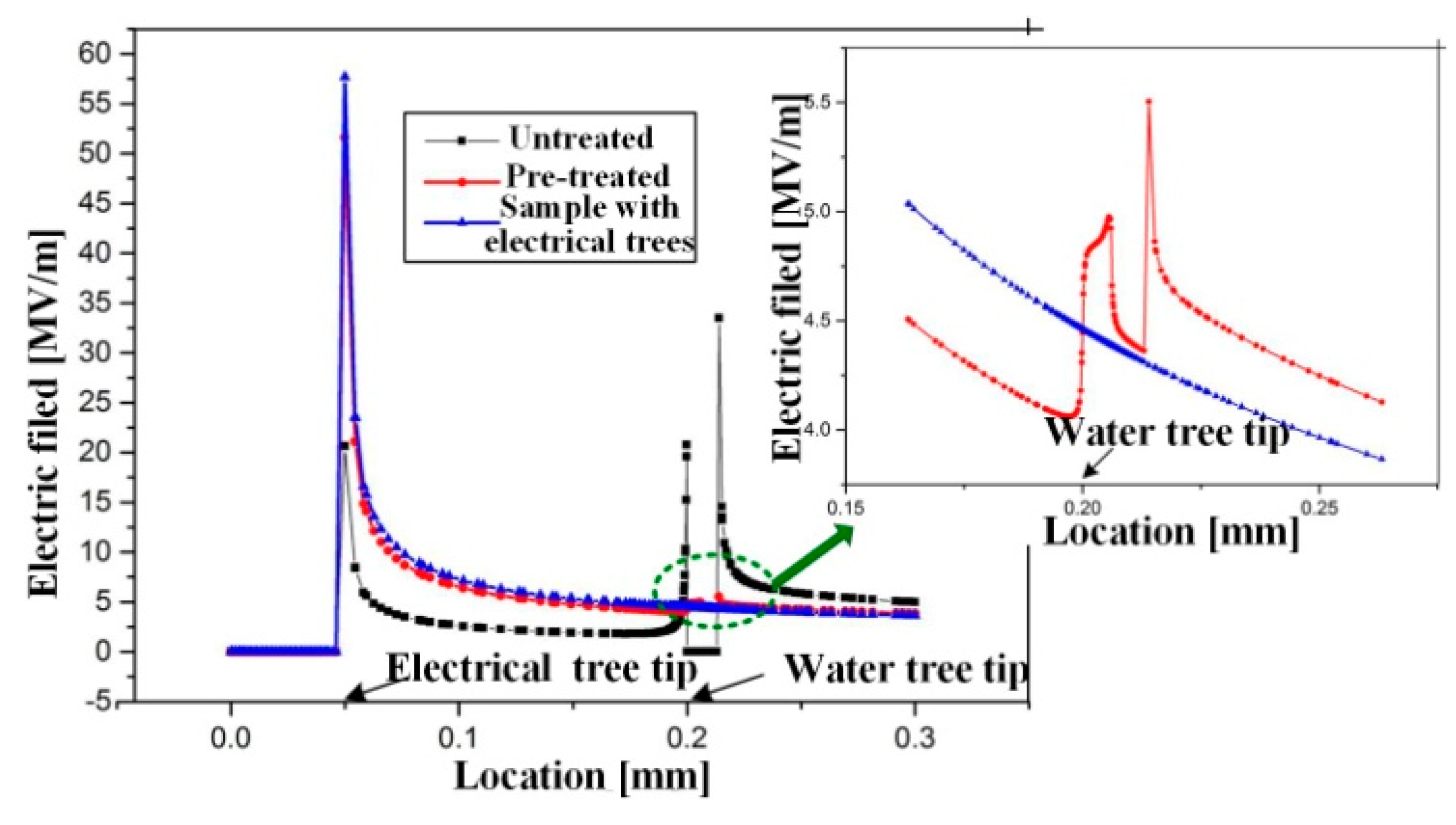
where ε0 is the vacuum permittivity, εr is the relative dielectric constant of the insulation layer, and E is the electric field. In this equation, it is known that the relative dielectric constant and electric field affect the Maxwell stress. In the pretreated cable samples, water molecules were consumed due to the hydrolysis–condensation reaction. Some particles with better dielectric performance were formed and stored in the XLPE. The values of εr in the pretreated cable samples were greater than those in the untreated cables. The electric field distribution in the XLPE around the pinhole was calculated based on the model in Figure 12. A 7.5 kV AC voltage (400 Hz) was applied in the model. The electric field distribution is shown in Figure 16. Before calculation, the highest relative dielectric constant of the region around the water needle tip in the pretreated XLPE was set to 5.3. In Figure 16, there are three series plotted. The black one is for untreated samples with electrical trees and water trees. The blue one is for untreated samples with only electrical trees and no water trees. The red one is for pre-treated samples with electrical trees and water trees.
The electric field at the electrical tree tip in the cable samples with electrical trees was 58 MV/m, which was much less than E0. Electrical trees are not easy to grow in cable samples under that AC voltage. At the water tree tip, the electric field in the untreated cable was higher than that in the pretreated cable. There were differences in the relative dielectric constant and the electric field distribution between the untreated cable and the pretreated cable. For the above reasons, the Maxwell stress in the pretreated cable was lower than that in the untreated cable. Water tree growth in the pretreated cable was inhibited. According to the experimental results, after cable aging for 576 h, the average tree length in the untreated cable samples and pretreated cable samples were similar. During the aging experiment, the residual rejuvenation liquid in the pretreated cable gradually decreased with time. The Maxwell stress in the pretreated cable increased with time.
4. Conclusions
In this study, rejuvenation liquid was injected into cable samples to prepare the pretreated cable samples. The prepared untreated cable samples and pretreated cable samples were subjected to aging under an AC voltage superimposed by an impulse voltage. The statistical electrical tree initiation rate and the average water tree length were tested in two groups of cable samples. To investigate the effect of rejuvenation liquid on inhibiting the initiation of trees, a calculation model was constructed by means of COMSOL software, resulting in the following conclusions.
- (1)
- The preinjected rejuvenation liquid has an inhibitory effect on electrical tree initiation and water tree propagation. This inhibitory effect is related to the concentration of the residual rejuvenation liquid. The inhibitory effect weakens as the amount of rejuvenation liquid is reduced.
- (2)
- In the pretreated cable sample, the dielectrophoretic force of the rejuvenation liquid molecules drives them to centralize around the needle tip. In addition, the relative dielectric constant of the insulation layer increases. The electric field distortion around the needle tip in the pretreated cable is weakened, and the electric field at the water tree tip is lower than that in the untreated cable. The preinjected rejuvenation liquid strongly contributes to reducing tree growth in cables.
Author Contributions
Conceptualization, G.Z.; Data curation, K.Z.; Formal analysis, W.G.; Investigation, M.H.; Resources, K.L.; Software, J.K.
Funding
This research was funded by the National Science Foundation of China, grant number 51477106, the Fundamental Research Funds for the Central Universities, grant number 2018SCU12003 and the Post-doctoral Science Foundation of China, grant number No. 2014M562323.
Acknowledgments
The authors thank the National Science Foundation of China under Projects No. 51477106 and the Fundamental Research Funds for the Central Universities No. 2018SCU12003 for providing financial support for this research. The authors also would like to thank the Post-doctoral Science Foundation of China No. 2014M562323 for providing financial support. We also give our appreciation to China Sichuan Star Cable Co., Ltd. for supplying the XLPE specimens.
Conflicts of Interest
The authors declare no conflict of interest.
References
- Eichhorn, R.M. Treeing in solid extruded electrical insulation. IEEE Trans. Dielectr. Electr. Insul. 1977, 1, 2–18. [Google Scholar] [CrossRef]
- Ross, R. Inception and propagation mechanisms of water treeing. IEEE Trans. Dielectr. Electr. Insul. 1998, 5, 660–680. [Google Scholar] [CrossRef]
- Ross, R. Effect of ageing conditions on the type of water treeing (power cables). IEEE Electr. Insul. Mag. 1993, 9, 7–13. [Google Scholar] [CrossRef]
- Ross, R.; Smit, J.J. Composition and growth of water trees in XLPE. IEEE Trans. Dielectr. Electr. Insul. 1992, 27, 519–531. [Google Scholar] [CrossRef]
- Zeller, H.R. Thermodynamics of Water Treeing. IEEE Trans. Dielectr. Electr. Insul. 1987, 22, 677–681. [Google Scholar] [CrossRef]
- Zeller, H.R. Breakdown and Prebreakdown Phenomena in Solid Dielectrics. IEEE Trans. Dielectr. Electr. Insul. 1987, 22, 115–122. [Google Scholar] [CrossRef]
- Opydo, W.; Dobrzycki, A. Detection of electric tree of solid dielectrics with the method of acoustic emission. Electr. Eng. 2012, 94, 37–48. [Google Scholar] [CrossRef]
- Dobrzycki, A.; Mikulski, S.; Opydo, W. Using ANN and SVM for the Detection of Acoustic Emission Signals. Accompanying Epoxy Resin Electrical Treeing. Appl. Sci. 2019, 9, 1523. [Google Scholar] [CrossRef]
- Schurch, R.; Rowland, S.M.; Bradley, R.S.; Withers, P.J. Imaging and analysis techniques for electrical trees using X-ray computed tomography. IEEE Trans. Dielectr. Electr. Insul. 2014, 21, 53–63. [Google Scholar] [CrossRef]
- Pelissou, S.; Lessard, G. Underground medium-voltage cable rejuvenation—Part I: Laboratory Tests on Cables. IEEE Trans. Power Deliv. 2011, 26, 2324–2332. [Google Scholar] [CrossRef]
- Meyer, D.F.; Vincent, G.A. Restoring Stranded Conductor Electrical Distribution Cable. U.S. Patent 4,766,011A, 23 August 1988. [Google Scholar]
- Pelissou, S.; Antoine, S.S. Underground medium-voltage cable rejuvenation—Part II: Pilot projects in the field. IEEE Trans. Power Deliv. 2011, 26, 2605–2612. [Google Scholar] [CrossRef]
- Moreau, E.; Mayoux, C.; Laurent, C.; Boudet, A. The structure characteristics of water trees in power cables and laboratory specimens. IEEE Trans. Dielectr. Electr. Insul. 1993, 28, 54–64. [Google Scholar] [CrossRef]
- Shimizu, N.; Laurent, C. Electrical tree initiation. IEEE Trans. Dielectr. Electr. Insul. 1998, 5, 651–659. [Google Scholar] [CrossRef]
- William, R.S. Cable Injection Technology. Proceedings of 2006 IEEE/PES Transmission & Distribution Conference and Exposition: Latin America, Caracas, Venezuela, 15–18 August 2006. [Google Scholar]
- Shu, W.; Boggs, S.A. Effect of cable restoration fluid on inhibiting water tree initial. IEEE Trans. Power Deliv. 2011, 26, 97–100. [Google Scholar] [CrossRef]
- Dissado, L.A. Understanding electrical trees in solids: From experiment to theory. In Proceedings of the 2001 IEEE 7th International Conference on Solid Dielectrics, Eindhoven, The Netherlands, 25–29 June 2001. [Google Scholar]
- Bahder, G.; Garrity, T.; Sosnowski, M.; Eaton, R.; Katz, C. Physical model of electric aging and breakdown of extruded polymeric insulated power cables. IEEE Trans. Power Appar. Syst. 1982, 101, 1378–1388. [Google Scholar] [CrossRef]
- Zhou, K.; Tao, X.; Wang, X.; Zhao, W.; Tao, W. Insight into the new role of titanium isopropoxide catalyst on reju-venation for water tree aged cables. IEEE Trans. Dielectr. Electr. Insul. 2015, 22, 611–618. [Google Scholar] [CrossRef]
- Elayyan, H.S.B.; Abderrazzaq, M.H. Electric Field Computation in Wet Cable Insulation Using Finite Element Approach. IEEE Trans. Dielectr. Electr. Insul. 2005, 12, 1125–1133. [Google Scholar] [CrossRef]
- Boggs, S.; Densley, J.; Kuang, J. Mechanism for Impulse Conversion of Water Trees to Electrical trees in XLPE. IEEE Trans. Power Deliv. 1998, 13, 310–315. [Google Scholar] [CrossRef]
- Radu, I.; Acedo, M.; Filippini, J.C.; Notingher, P.; Ftutos, F. The effect of water treeing on the electric field distribution of XLPE. IEEE Trans. Dielectr. Electr. Insul. 2000, 7, 860–868. [Google Scholar] [CrossRef]
- Thomas, J.; Saha, T.K. A New Dielectric Response Model for Water Tree Degraded XLPE Insulation—Part A: Model Development with Small Sample Verification. IEEE Trans. Dielectr. Electr. Insul. 2008, 15, 1131–1143. [Google Scholar] [CrossRef]
- Zhou, K.; Tao, X.; Zhao, W. A cable rejuvenation method based on formation of nano-TiO2 inside water tree and its insulation enhancement mechanism. Proc. CSEE 2013, 33, 202–210. [Google Scholar]
- Peschke, E.; von Olshausen, R. Cable systems for high and extra-high voltage development, manufacture, testing, installation and operation of cables and their accessories. IEEE Electr. Insul. Mag. 2001, 175, 60. [Google Scholar]
- Wang, Z.; Marcolongo, P.; Lemberg, J.A.; Panganiban, B.; Evans, J.W.; Ritchie, R.O.; Wright, P.K. Mechanical fatigue as a mechanism of water tree growth in TR-XLPE. IEEE Trans. Dielectr. Electr. Insul. 2012, 19, 321–330. [Google Scholar] [CrossRef]
- Zhou, K.; Li, K.; He, Y.; Zhu, G. A new insight into the influence of mechanical orientation on water tree propagation in abnormal water tree shapes. IEEE Trans. Dielectr. Electr. Insul. 2017, 24, 3878–3886. [Google Scholar] [CrossRef]
Figure 1.
Cable sample and principle of the rejuvenation liquid injection experiment.
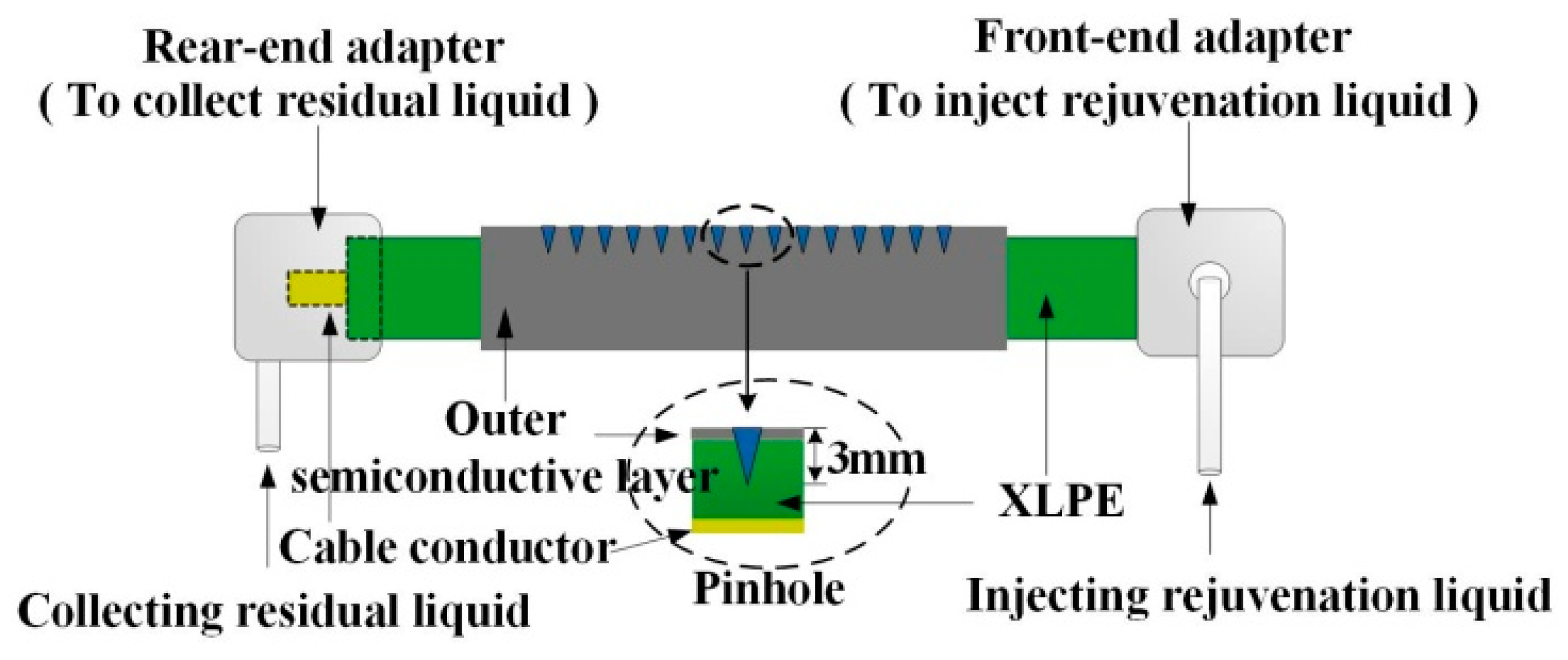
Figure 2.
Schematic diagram of the cable aging experiment.
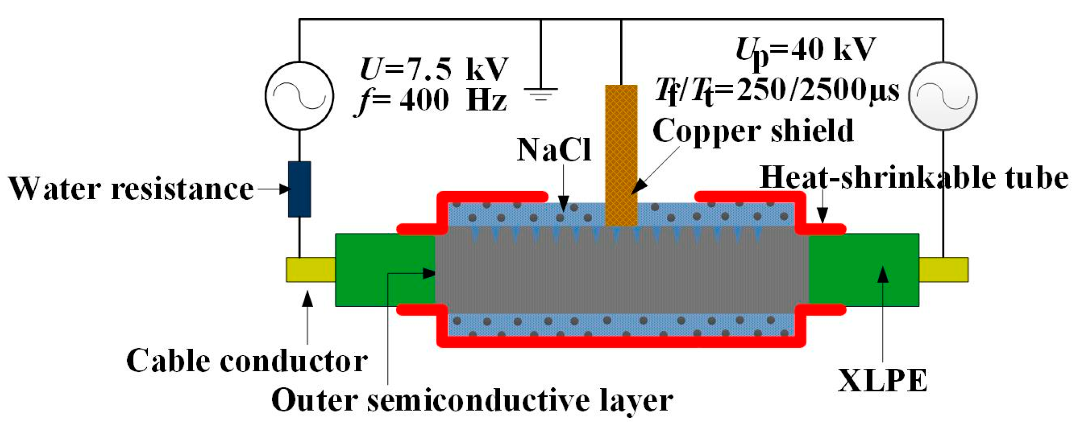
Figure 3.
Test platform of the cable aging experiment.
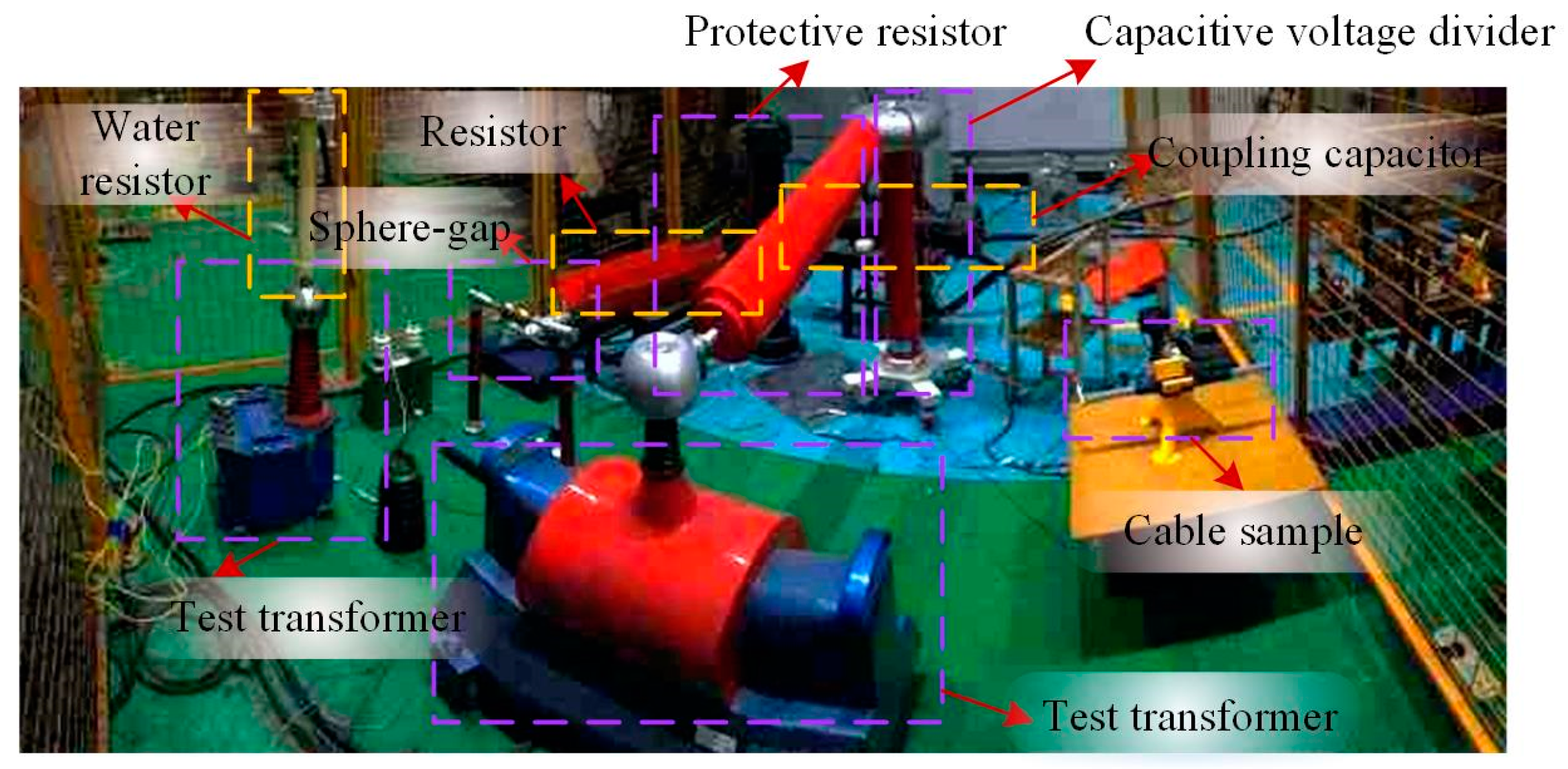
Figure 4.
The microscope observation system.
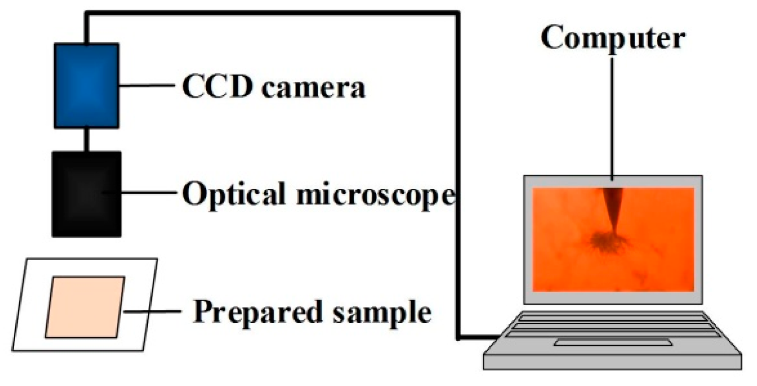
Figure 5.
Tree micromorphology of group A slices after aging for 288 h: (a) untreated cable sample; (b) pretreated cable sample.
Figure 5.
Tree micromorphology of group A slices after aging for 288 h: (a) untreated cable sample; (b) pretreated cable sample.
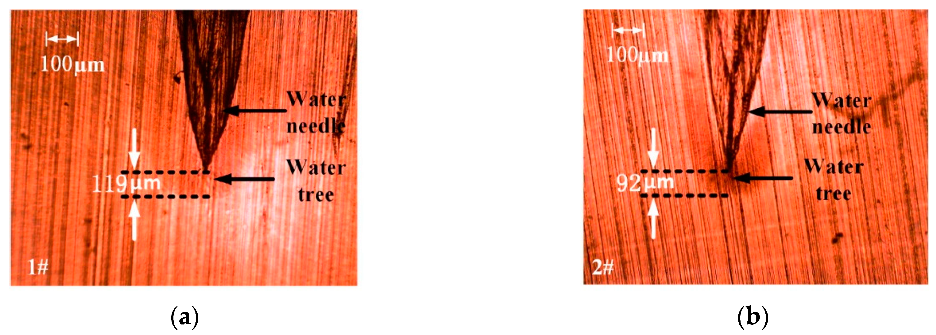
Figure 6.
Tree micromorphology of group B slices after aging for 288 h: (a) untreated cable sample; (b) pretreated cable sample.
Figure 6.
Tree micromorphology of group B slices after aging for 288 h: (a) untreated cable sample; (b) pretreated cable sample.
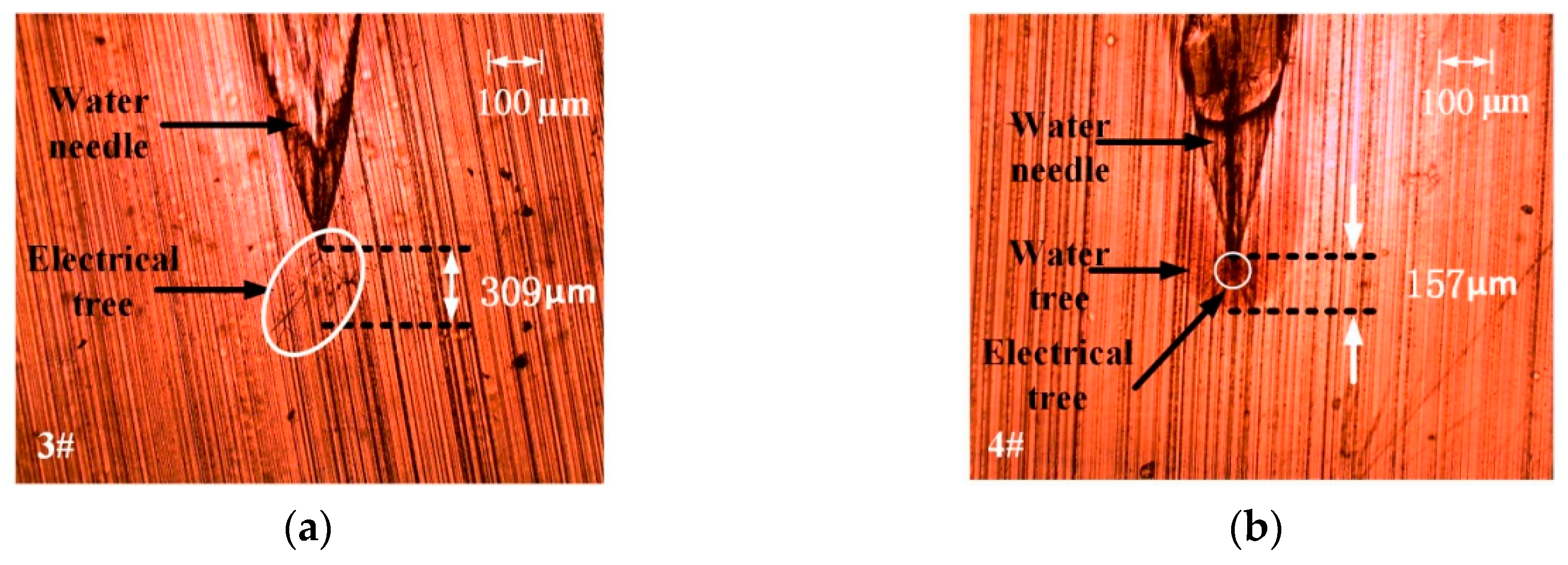
Figure 7.
Tree micromorphology of group A slices after aging for 576 h: (a) untreated cable sample; (b) pretreated cable sample.
Figure 7.
Tree micromorphology of group A slices after aging for 576 h: (a) untreated cable sample; (b) pretreated cable sample.

Figure 8.
Tree micromorphology of group B slices after aging for 576 h: (a) untreated cable sample; (b) pretreated cable sample.
Figure 8.
Tree micromorphology of group B slices after aging for 576 h: (a) untreated cable sample; (b) pretreated cable sample.
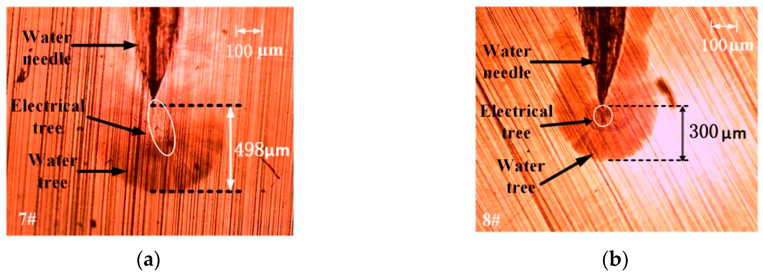
Figure 9.
Statistical assessment of the average tree length.
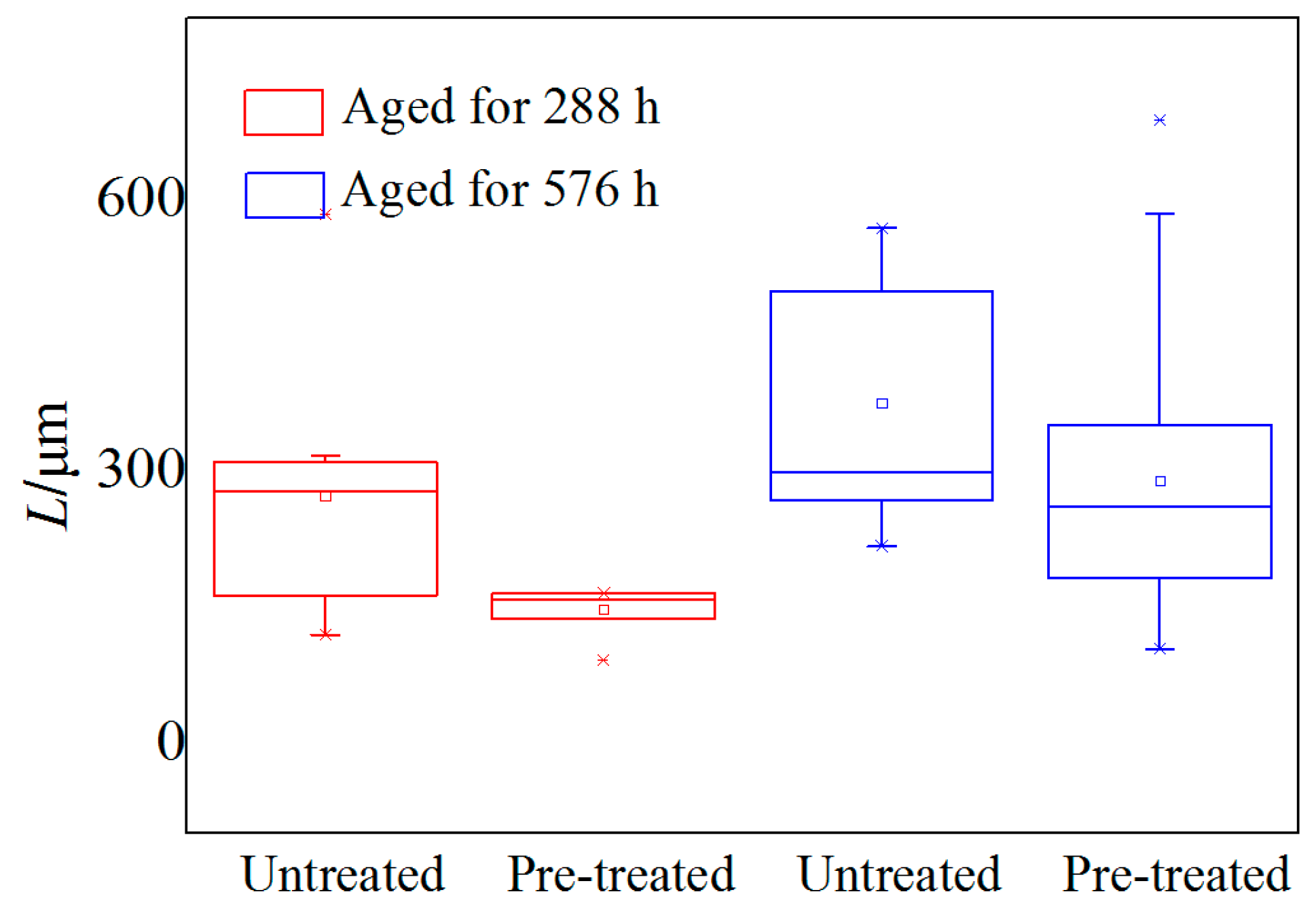
Figure 10.
Pretreated cable slice observed by SEM.
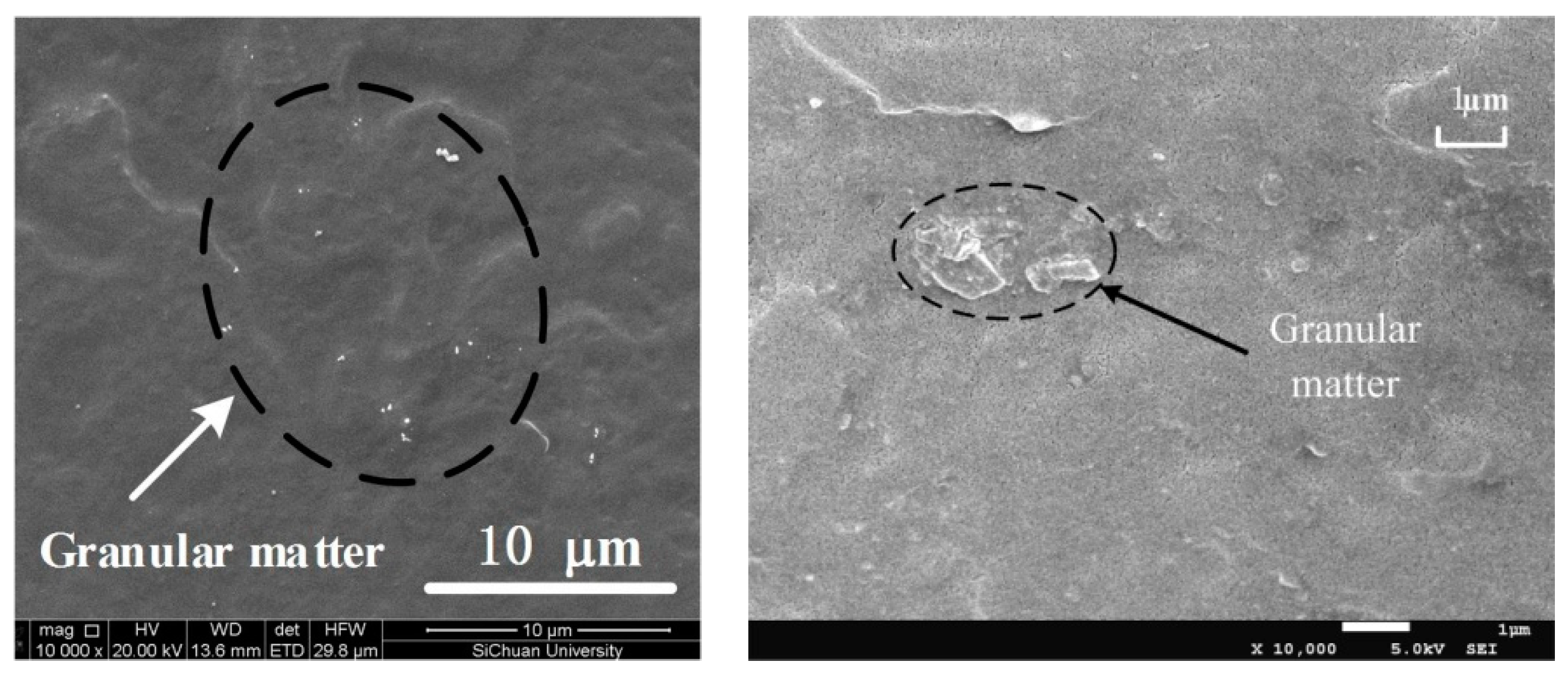
Figure 11.
Analysis of granular matter by EDS.

Figure 12.
A model of the electric tree and water tree: (a) model of the cable; (b) details and sizes of the water tree and the electrical tree.
Figure 12.
A model of the electric tree and water tree: (a) model of the cable; (b) details and sizes of the water tree and the electrical tree.

Figure 13.
Migration of rejuvenation liquid molecules: (a) preinjected rejuvenation liquid diffusion from the cable conductor to the insulation layer; (b) centralization of rejuvenation liquid molecules to the needle tip.
Figure 13.
Migration of rejuvenation liquid molecules: (a) preinjected rejuvenation liquid diffusion from the cable conductor to the insulation layer; (b) centralization of rejuvenation liquid molecules to the needle tip.
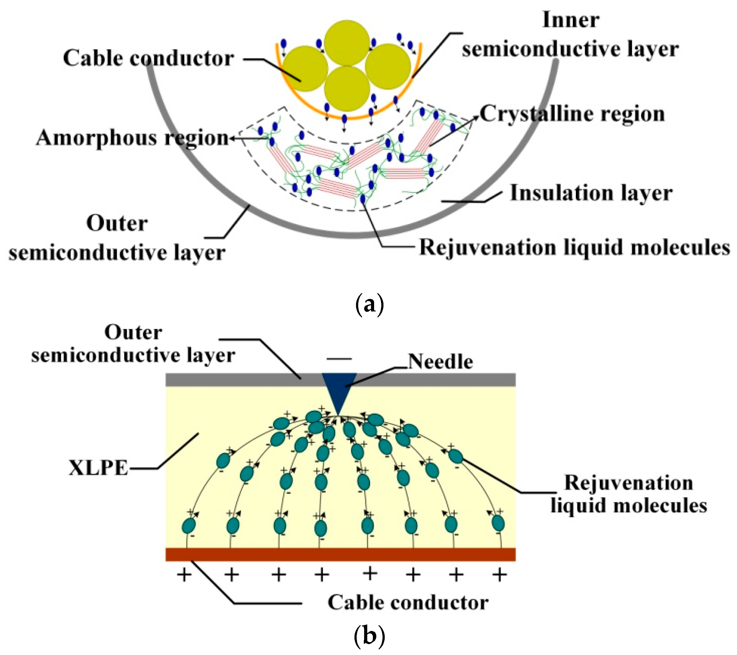
Figure 14.
Electric field distribution in the untreated and pretreated cables.
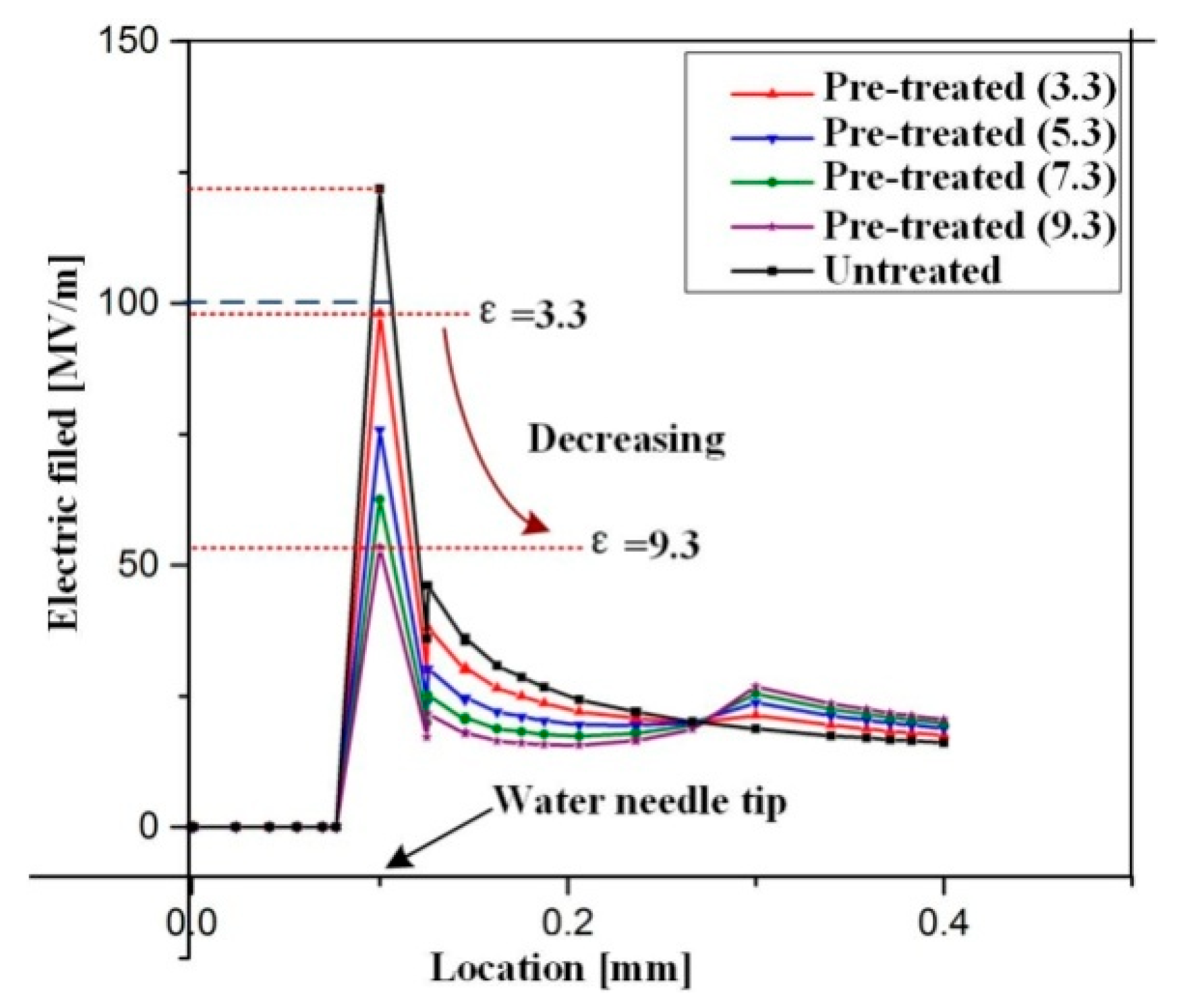
Figure 15.
Growth of a water tree in the pretreated cable: (a) under no electric field; (b) water and rejuvenation liquid molecule penetration after molecular chain rupture.
Figure 15.
Growth of a water tree in the pretreated cable: (a) under no electric field; (b) water and rejuvenation liquid molecule penetration after molecular chain rupture.
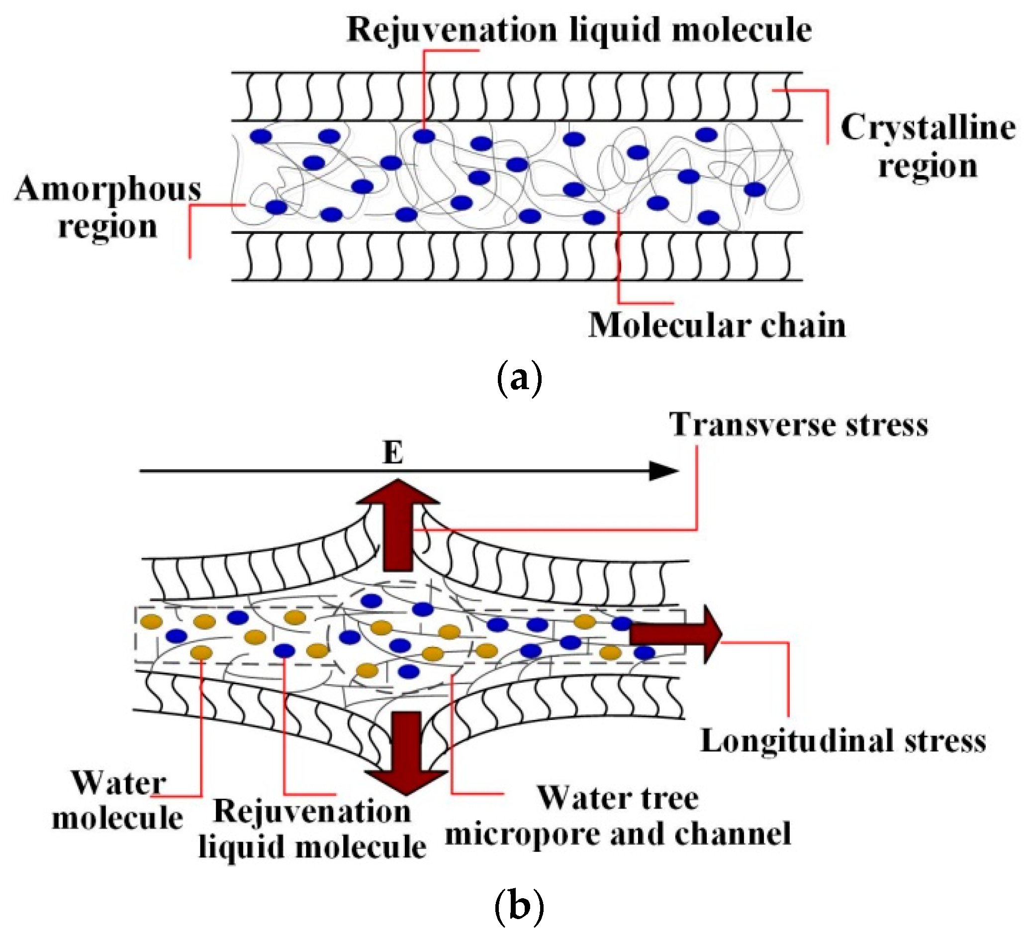
Figure 16.
Electric field distribution in the area around the water needle in XLPE.

Table 1.
The statistical initiation rates of electrical trees and average tree length.
| Statistical Parameters | At First Stage (Aged for 288 h) | At Last Stage (Aged for 576 h) | ||
|---|---|---|---|---|
| Untreated | Pretreated | Untreated | Pretreated | |
| P (%) | m0 = 14, m = 8 | m0 = 7, m = 1 | m0 = 25, m = 5 | m0 = 15, m = 4 |
| 57.1 | 14.3 | 20 | 26.67 | |
| The root mean squared error (RMSE) of P (%) | 57.1 ± 13.2 | 14.3 ± 13.2 | 20 ± 8 | 26.67 ± 11.4 |
| L (μm) | 272 | 144 | 375 | 288 |
Table 2.
Parameters of the model.
| Part | Parameters | |
|---|---|---|
| εr | γ (S/m) | |
| XLPE | 2.3 | 1 × 10⁻¹⁷ |
| Water tree body | 10 | 1 × 10⁻¹⁰ |
| NaCl solution | 8.5 × 10⁷ | 2.0 |
| Polysiloxane | 2.8 | 1 × 10⁻¹¹ |
| Semiconductive layer | 20 | 1 × 10⁻⁴ |
| Electrical tree | 80 | 2.0 |
© 2019 by the authors. Licensee MDPI, Basel, Switzerland. This article is an open access article distributed under the terms and conditions of the Creative Commons Attribution (CC BY) license (http://creativecommons.org/licenses/by/4.0/).
Share and Cite
MDPI and ACS Style
Zhu, G.; Zhou, K.; Gong, W.; He, M.; Kong, J.; Li, K. Inhibition of Rejuvenation Liquid on Trees in XLPE Cables under Switching Impulse Voltages. Energies 2019, 12, 2133. https://doi.org/10.3390/en12112133
AMA Style
Zhu G, Zhou K, Gong W, He M, Kong J, Li K. Inhibition of Rejuvenation Liquid on Trees in XLPE Cables under Switching Impulse Voltages. Energies. 2019; 12(11):2133. https://doi.org/10.3390/en12112133
Chicago/Turabian StyleZhu, Guangya, Kai Zhou, Wei Gong, Min He, Jiaming Kong, and Kangle Li. 2019. "Inhibition of Rejuvenation Liquid on Trees in XLPE Cables under Switching Impulse Voltages" Energies 12, no. 11: 2133. https://doi.org/10.3390/en12112133
Note that from the first issue of 2016, this journal uses article numbers instead of page numbers. See further details here.