The Influence of Stator Winding Turns on the Steady-State Performances of Line-Start Permanent Magnet Synchronous Motors

Zhengzhou University of Light Industry, School of Electrical and Information Engineering, Zhengzhou 450000, Henan, China
*
Author to whom correspondence should be addressed.
Energies 2019, 12(12), 2363; https://doi.org/10.3390/en12122363
Submission received: 27 April 2019
/
Revised: 9 June 2019
/
Accepted: 15 June 2019
/
Published: 19 June 2019
(This article belongs to the Special Issue Electrical Machine Design)
Abstract
:The variation of stator winding turns will directly affect the key parameters of a motor, such as winding resistance and winding reactance, which further affect the steady-state performance of the motor. In order to get excellent steady-state performance from line-start permanent magnet synchronous motors (LSPMSMs) under different load powers, taking an 11 kW LSPMSM as an example, the finite element method (FEM), combined with the steady-state phasor diagram and torque angle characteristic, are used in this paper for the optimal design of the stator winding turns of the prototype. The correctness of the model is verified by comparing the experimental data with the calculated data. First, the influences of different stator winding turns on the no-load, back-induced electromotive force (EMF), as well as on inductance and overload ability are studied, and the variation mechanism is obtained. In addition, from the perspective of the torque angle characteristic, the influence of the change in synchronous inductance caused by the number of turns on the steady-state power angle is studied. Second, the variation of the current and power factors with turn number is obtained by studying the steady-state power angle and end voltage. Based on the coupling relationship between the no-load back EMF and the power angle, the mechanism of non-linear variation of current and power factor is revealed. Finally, the variation of the number of turns on the core loss and eddy current loss is analyzed under various operating conditions, and the variation mechanism is revealed, based on the armature reaction theory.
1. Introduction
Line-start permanent magnet synchronous motors (LSPMSMs) have the advantage of a high power factor, high efficiency, wide economic operation range, and high power density by using a permanent magnet (PM) to generate a strong magnetic field [1,2,3,4,5]. At the time, brake torque occurs and causes a major drawback for the starting period by decreasing the start torque [6,7,8]. In addition, the LSPMSM keeps synchronous speed in a steady state, and the ability of the rotor to pull in synchronization is also a key point for LSPMSMs [9,10,11]. Therefore, more attention has been focused on the above issues, and the steady-state performances of LSPMSMs is easily neglected. The LSPMSM is different from a permanent magnet synchronous motor (PMSM) or an induction motor (IM), because of its special rotor structure. The rotor has both permanent magnets and cages; thus, the motor parameters have different influences on the steady-state performance, to some extent. There has been some literature on the study of steady-state performance, such as the influence of rotor bar depth, the frames of rotor, the stator winding connection mode, the winding structure, and the capacitor for the steady-state performances, invested respectively in [12,13,14,15], and so on. However, most studies have been exclusively concentrated on rated load power and neglected the influence on another load power. In fact, the motors not only work on rated load power, but have a range for different operational conditions. Therefore, the study of steady-state performance of line-start permanent magnet synchronous motors under different load powers is significant.
In this paper, the influence of the stator winding turns on the steady-state performance of LSPMSMs is studied. The winding turns have a direct effect on the induced electromotive force (EMF), stator resistance, end leakage reactance, synchronous reactance, etc. The performance of the motors will then be changed to some extent. It is convenient to change the performance by changing the stator winding turn value. Under normal conditions, the initial stator winding turn value is designed by the conventional calculation of the electromagnetic and thermal loads—besides, some experience is needed. This is not an accurate value. Changing the stator winding turns to some extent under the initial value is feasible.
The prototype is single-layer winding and the number of parallel branches is one. In order to simplify the analysis, the stator winding turns in particular represent the numbers of winding turns at a pitch called Ns throughout this study. The prototype operates in three-phase power of 380 V and 50 Hz. Based on the two-dimensional (2-D) finite element method (FEM), combined with the steady-state phasor diagram and torque angle characteristic, variation in the current, power factor, and maximum torque with the different stator winding turns is studied under different load powers for a 11 kW, LSPMSM-adopted, V-shape PM.
2. Two-Dimensional Finite Element Analysis Model and Parameters
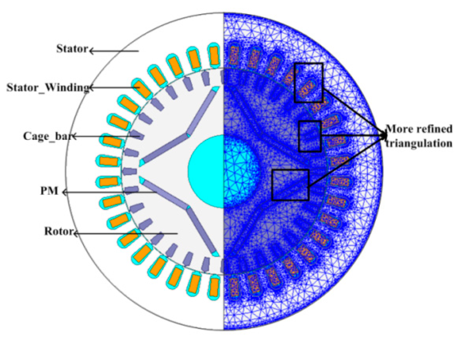
The two-dimensional (2-D) finite element analysis (FEA) model was built, and the 2-D cross-section of the motor perpendicular to the axial direction was selected as the analysis model, as shown in Figure 1. In this paper, the electromagnetic field of the motor does not take into account the influence of displacement current, and belongs to a quasi-steady field. In the process of finite element calculation, we consider the linear B–H curve. The vector magnetic potential A and current density J only has the z-component. The transient 2-D electromagnetic field calculation equation could be described as
where μ is the permeability, A is the magnet vector potential, Jz is the source current density, n is the normal unit vector of the external permanent magnet, Js is the equivalent current density of the permanent magnets, σ is conductivity, t is time, l is the boundary between the equivalent surface current layer of permanent magnet material and other materials, Γ1 is the first-type boundary, and Γ2 is the second-type boundary.
In the numerical calculation of the 2-D electromagnetic field of an LSPMSM, the equivalent surface current is used to simulate the permanent magnet, and the equivalent surface current can be represented by surface current density Js:
Here, where n is the normal unit vector of permanent magnet, Js is the equivalent current density of the permanent magnets, Mr is the remanent magnetization, μr is the relative recovery permeability.
When the magnetic vector potential is used to describe the field, at the boundary line between the equivalent surface current layer of the simulated permanent magnet and other media, the following boundary conditions are used:
where l is the boundary between the equivalent surface current layer of permanent magnet material and other materials, the ν is the reluctivity, A is the magnet vector potential, n is the normal unit vector of the external permanent magnet, Js is the equivalent current density of the permanent magnets.
When the FEM is used to solve the motor electromagnetic field, the range of solution areas should be minimized as much as possible. Because the permeability of ferromagnetic materials is far greater than the air permeability, the outer surface of the motor is used as the boundary surface. In other words, the magnetic force lines are closed along the outer surface of the motor, which belongs to the first-type boundary condition (Γ1). The second-type boundary condition (Γ2) is mainly applied to the interface of different materials in the motor, such as the interface between the motor cores and the air. It can be considered that the magnetic force lines are vertically crossed, and the variation of the magnetic potential along the geometric neutral line of the magnetic poles is 0—that is, .
The fundamental parameters of the prototype are shown in Table 1. Based on the FEM, the numerical simulation of the model was obtained, and the result was verified by comparing it with the experimental data, as shown in Table 2. The testing platform of the prototype is shown in Figure 2. The masses of prototype materials are shown in Table 3. Considering the losses of stator-core and rotor-eddy current in this study, the space harmonics should be calculated more carefully, so that the precise numerical simulation of the losses can be obtained. The Ns is the number of turns. Some measures are needed, as follows.
The parts of the stator tooth, the edge between stator tooth and yoke, and the cages and permanent magnets of the model are more refined during triangulation, as shown in Figure 1.
The time step is equal to one-eighth of the time when the rotor moves a slot pitch, and it can be described as the equation [16]
where f is the line frequency, P is the number of pole pairs, and N is the number of stator slots. Using the equation, the time step Δt is 1.38 × 10⁻⁴ s.
It can be seen from Table 3 that the number of turns has no effect on the masses of the stator rotor core, permanent magnet, or the squirrel cage. When the number of turns is changed, the wire diameter of winding should also be changed, so as to keep the copper filling factor constant.
3. The Influence of NS on the Current, the Power Factor, and Maximum Torque
It is obvious that the winding turns have a direct effect on the induced EMF, as well as on the no-load, back-induced EMF (called E0 in next analysis); stator resistance; end leakage reactance; and synchronous reactance. Then the performance of the motors will be changed, to some extent. In this paper, the process used for the study of the stator winding turns can be presented in Figure 3.
The initial NS value is designed by the conventional calculation of the electromagnetics load, the thermal load, and some experience. As determined through the procedure shown in Figure 3, the range of the NS is from 27 to 33. Considering that the range is not large, and the initial stator resistance and end leakage values are little, they could therefore be ignored to simplify the calculation and analysis.
In the study, the steady-state phasor diagram under different loads can be utilized. Two factors are needed for this method. One is E0, which can be obtained precisely by FEM. The E0 with a different NS, obtained through FEM, is shown in Table 4.
A combination of the finite element method and the analytical calculation method is used to solve Xd and Xq. Xd and Xq are the quadrature axis reactance and direct axis reactance. The finite element method is used to calculate the voltage; power angle; power factor angle; no-load, back-induced EMF; resistance; and other parameters. The motor vector diagram is used to solve for Id and Iq. Finally, Xd and Xq are obtained by the analytical method. The calculation formula is as follows:
where E0 is the no-load, back-induced EMF; Id and Iq are the quadrature axis current and direct axis current, respectively; R1 is the resistance; θ is the power angle; and U is the voltage.
The other factor when using this method is the torque angle under different load powers, which can be estimated by the torque angle characteristic and the equation for the torque (neglecting the stator resistance), stated below as [3]
where Tem is electromagnetic torque; m is the number of voltage phase; U is the line voltage; ω is the angular velocity of the rotor; Xq and Xd are the quadrature and direct axis reactance, respectively; p is the number of pole pairs, and θ is the torque-angle. Generally speaking, E0 is directly proportional to NS. In addition, the reactance is directly proportional to the winding turns squared. Assume that k is equal to the ratio of N2 to N1, where N1 and N2 represent different values of NS. When the value of the NS is N1, the Tem is as shown in Formula 3. Then, when the value of NS is N2, the formula can be described as
When N2 is less than N1, then k is less than 1. It is clear that the maximum value of Tem is less than the maximum value of T*em, and the conclusion can be gained that the maximum electromagnetic torque decreases as the value of NS increases. However, estimating Xq and Xd involves saturation and the cross-coupling effect [17]. The accurate values are difficult to obtain. By 2-D FEM, the clear results are obtained, as shown in Figure 4. The Tem is approximately consistent when the θ changes within the range of 0° to 40°, and with the increase of θ, the change of Tem gradually become distinct. The maximum is reached near 100°, and the result is consistent with the above analysis.
The average torque of the LSPMSM is an important index to measure the performance of the motor in steady-state operation, which directly determines the ability of the motor to drag its load. The torque waveform and its Fourier decomposition is shown in Figure 5.
When the number of turns is 29, the torque waveform and Fourier decomposition at no-load and rated-load operation are as shown in Figure 5. The torque ripple of the motor at no-load is smaller than that at rated-load. The third, fifth, and seventh harmonic content of the torque is larger at a rated load than in the no-load state. With the increase of motor load torque, the motor harmonic content also increases. In addition, the cogging torque of the motor also causes the torque ripple of the motor. The LSPMSM torque ripple at rated-load operation is not more than 4% [18]. However, the prototype is a first-generation motor. The torque ripple of the LSPMSM will be optimized in the follow-up work. The influence of stator winding turns on the steady-state performance of an LSPMSM is studied emphatically in this paper.
Neglecting the stator resistance and end leakage, the steady-state phasor diagram can now be depicted by
where U is the phase voltage, which is equal to the line voltage, due to the delta connection; and is is the phase current. The steady-state phasor diagram under different loads is shown in Figure 6.
In Figure 6, the A, B, and C represent the phasor diagram under different loads, which can be described as three states of light load, near-rated load, and overload, respectively. Under a light load, the E0 has a key effect on the stator current and PF change, and the effect is nonlinear. The PF is the power factor. Whether or not E0 is high or low enough, the d-axis current component will get larger, which causes the stator current to increase and PF to decrease.
With the load torque from A to B, the torque angle gradually increases, and the influence of E0 gradually decreases. The stator current and PF with different NS values are approximately consistent. When the load torque continues to go up, as shown in Figure 4, the torque angle with different NS values become distinct, and its influence on the stator current and PF is gradually getting stronger, corresponding to the Figure 6C.
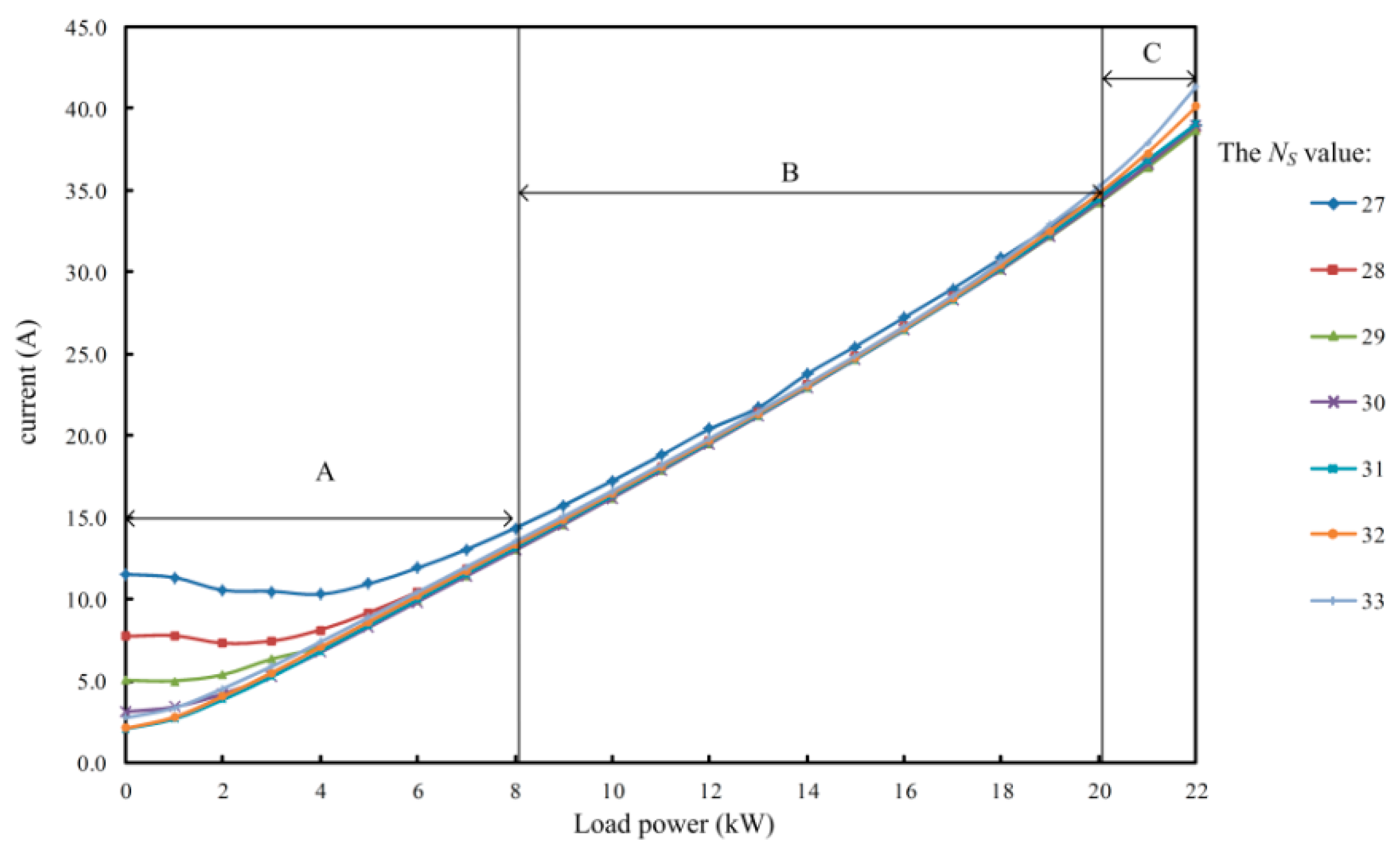
The specific changes of the line current and PF, calculated by FEM, are shown in Figure 7 and Figure 8, respectively.
As is shown in Figure 7 and Figure 8, the variation of the current and PF with NS are consistent with the above analysis. In Figure 6, A, B, and C approximately correspond to the area of A, B, and C in Figure 7. When NS is 31, the value of E0/U is 1.01, and the current is at its minimum of 2.07 A at no-load operation. Then the current increases or decreases with the value of NS, as it goes up or down. Defining the load rate is a ratio of the fact load and the rated load. When the load rate is from 0 to 0.7, the current and PF difference with a different NS is clear, and tends to be small. When the load rate is from 0.7 to 1.8, the differences between the stator currents and PF with different NS are almost consistent. With the load rate continues to go up, the clear difference occurs again, and the value of the current increases as the value of NS decreases. Take NS equaling 27 and 33 as an example—the variation can be seen clearly in Figure 9.
According to the demands of the prototype, the PF value of 0.94 was chosen was an index, so the influence of different NS values on the current, the power factor, and maximum torque can be described in Figure 10.
As is shown in Figure 10, the range of the PF value, which is greater than or equal to 0.94, increases first, and then decreases with as the NS value increases; the range is at its maximum when NS equals 30 or 31. The change of range mainly appears at the light load, indicating that the change of E0 value with NS dominates the variation of stator current and PF. Besides, the maximum load decreases as the NS value increases nearly 1 kW per turn. This can be seen from Figure 4. This is because the synchronous reactance decreases as the NS value increases, causing the load angle to be smaller than in a fixed load.
4. The Effect of Turn Number on the Moment of Inertia, Starting Torque, and Starting Current
4.1. The Analysis about Moment of Inertia
The moment of inertia is an important parameter of the LSPMSM, which directly affects the starting ability of the LSPMSM. The maximum moment of inertia of the LSPMSM is calculated based on the finite element method, as shown in Figure 11.
It can be seen from Figure 11 that when the number of turns increases, the maximum moment of inertia of the motor decreases, and the pulling-in-synchronization capability is greatly reduced. With the increase of the number of turns, although the no-load, back-induced EMF is increased, the direct-axis synchronous reactance increases more (because it is proportional to the square of the number of turns). The ratio of the no-load, back-induced EMF to the direct-axis synchronous reactance is reduced, and the permanent magnet torque is reduced. In the pulling process, the maximum kinetic energy provided by permanent magnet torque is reduced. In addition, the increase of the no-load, back-induced EMF causes the increase of the braking torque. Therefore, the pulling-in-synchronization capability is reduced.
4.2. The Influence of the Number of Turns on the Starting Current and Starting Torque
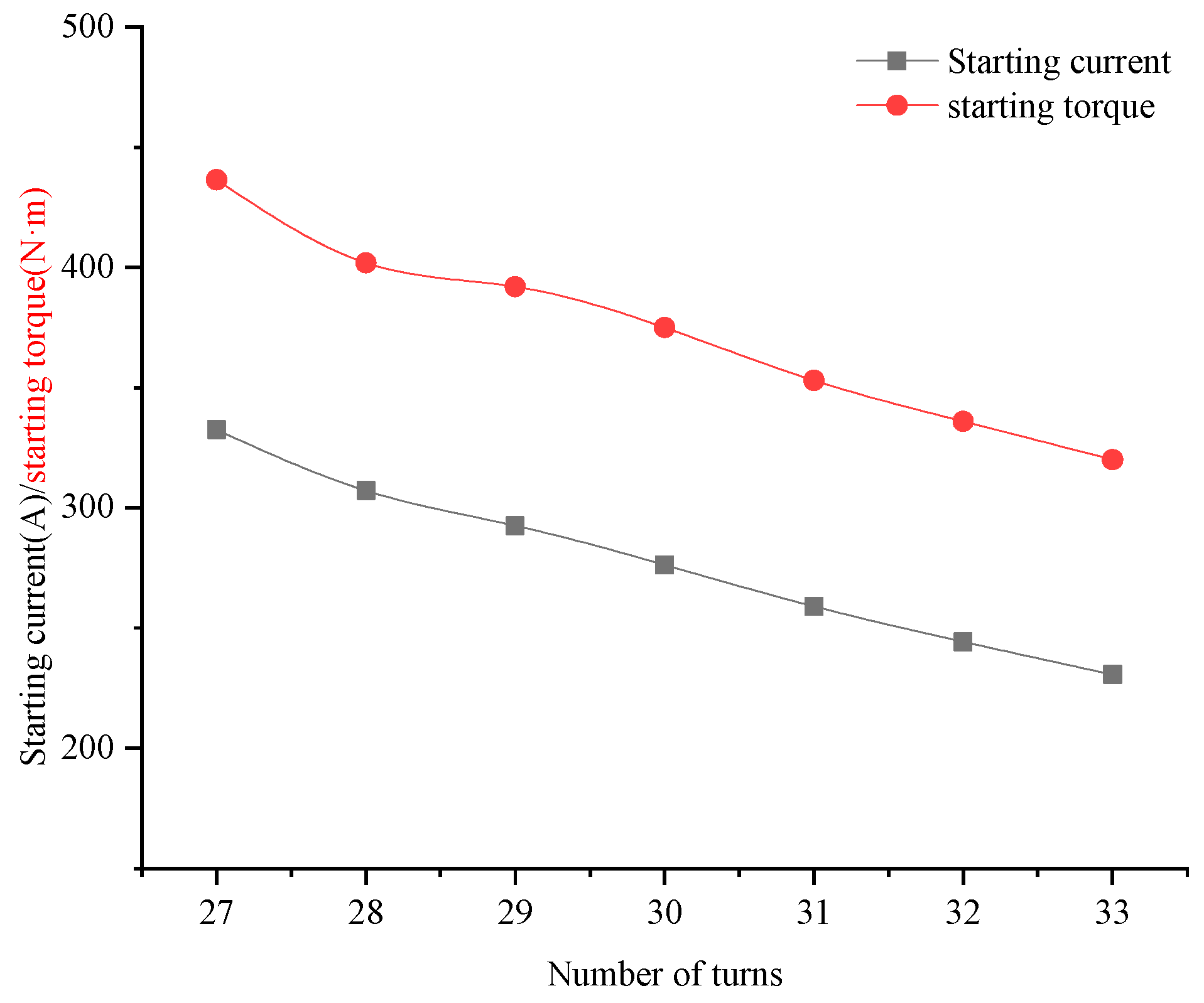
The starting torque and starting current of the LSPMSM is another important parameter, which is an important index of whether the motor can start smoothly. Therefore, it is important to study the starting torque and the current of the motor. The starting torque and starting current of the LSPMSM are calculated based on the finite element method, as shown in Figure 12.
It can be seen from Figure 12 that with the increase of the number of turns, the starting current and starting torque of the LSPMSM is reduced. When the number of turns is 27, the starting current is 332.5 A. When the number of turns is 33, the starting current of the motor is 230.6 A. When the number of turns of increases by six turns, the starting current decreases by 30.6%. When the number of turns is 27, the starting torque is 436.5 N·m. When the number of turns is 33, the starting torque is 320 N·m. When the number of turns of increases by six turns, the starting current decreases by 27%.
5. The Analysis of Losses
In this paper, the parameters of the prototype are constant except for the NS, and the current and load angle in a fixed load torque are different with changes in the NS value. This will cause the armature reactions to be different, and then the motor magnetic field is changed. The losses of stator core and rotor eddy current are closely related to the magnetic field. Therefore, the losses change with the NS value. The stator core losses and rotor-eddy current losses with the different NS values can be studied by FEM.
5.1. Stator Core Losses
The iron loss can be separated into the hysteresis loss and eddy current loss. The stator core is made of thin lamination made by a silicon steel sheet, so the eddy current losses in the stator core losses are neglected. Therefore, the stator core losses per electrical cycle can be obtained by [19].
where N is the number of loops, Kh is the hysteresis coefficient, Bpeak is the peak flux density, k is a constant between 0.6 and 0.7, a and b can be fixed by the curve fitting of the measured loss data, and ΔBi is the flux reversal associated with a given minor loop. The stator core loss with different NS values versus load power is shown in Figure 13.
As shown in Figure 13, there are approximately two states under all load power. In the first state, when the value of load rate is from 0 to 1 and Ns is constant, the changes of the stator core losses are small. In the second state, the rate of stator core loss increase becomes increasingly large, and the stator core losses increase distinctly. With the NS value increase, the increase rate of the stator core losses rises. In the steady state, the induced EMF is approximately equal to phase voltage U, which is a constant value. With the NS value increase, the mutual flux decreases, which can be obtained by
where the E is the induced EMF, f is the line frequency, N is the turns-in-series per phase, Kω is the winding coefficient, and Φ is the mutual flux. The flux density of the stator field decreases. Therefore, the stator core losses decrease when the stator winding turns increase. In the first state, the influence of armature reactions is not enough to change the stator core losses distinctly. With the load power increase, this influence becomes increasingly stronger, so that the stator core loss increase distinctly corresponds to the second state.
5.2. Eddy Current Losses
In a steady state, the LSPMSM works as a synchronous machine, and rotor losses are caused by the harmonic magnetic field, which rotates asynchronously. In addition, the rotor losses are mainly eddy current losses concentrated on the permanent magnets and cages. The eddy current losses can be estimated by [20]
where Peddy is the eddy current loss, Te is the period of time, Je is the current density in per element, lt is the axial length of rotor, σr is conductivity of the eddy current area, and Δe is the element area. The change in eddy-current loss with NS under different load powers is shown in Figure 14.
As is shown in Figure 14, the change of eddy current loss is obvious. At the beginning, with the NS value increasing, the eddy current losses decrease until the NS value is 32; the value of the eddy current loss is minimal. As the NS continues to improve, the eddy current loss increases as well. However, with the NS value increasing, the increase rate of eddy current loss also increases. Therefore, when the load power reaches a certain level of approximately rated load power, the NS value is bigger, and the eddy current loss is larger. With the load power increase, the armature reaction increases constantly. This makes the air-gap distortion degree of the magnetic field and the harmonic magnetic field increase. Therefore, the eddy current losses increase, and with the NS value increasing, the influences of the armature reaction strengthen.
The stator core loss and rotor eddy current loss of the motor with different turns are analyzed. In order to more directly compare the influence of turns on the motor loss, the variation of motor efficiency with different turns is given in Figure 15.
It can be seen from Figure 15 that with the increase of the number of turns, the motor efficiency increases under low load power. With an increase in the number of turns, the motor efficiency gradually decreases under high load power. At 4 kW of load power, when the number of turns increases from 27 to 32, the efficiency increases by 2.45%. At 20 kW load power, when the number of turns increases from 27 to 32, the efficiency decreases by 2.7%.
6. Conclusions
In this paper, the influence of NS on the steady-state performance of LSPMSMs, including stator current, power factor, stator core loss, and eddy current loss were obtained. It is noticeable that the analysis about the losses is not embedded, and in the next work these will be specially studied in-depth. The conclusions can be summarized as follows:
1. The influence of the stator winding turns for the current and PF can mainly be illustrated by two aspects. At light load, the approximate load rate is less than 0.7; in this paper, the main effect of the change of current and PF is the change of E0 due to the change of NS. However, with the load power increasing, the effect of E0 gradually weakens, and the effect of the change of synchronous reactance becomes stronger, so the stator current and PF tend to be consistent. Even when the load is large enough, the stator winding turns is higher, and the stator current is smaller. Finally, the capacity of overload improves as the NS value decreases.
2. For the stator core losses, when the armature reaction is not taken into account, the stator core losses will decrease with an increasing NS value. In contrast, as the load power increases, the rate of the stator core losses increase rises as NS value increases. What is more, this phenomenon is clear when the load power reaches the overload state.
3. The change of eddy current losses caused by an armature reaction at different NS values. In addition, the rate of the eddy current losses rise as the NS value increases.
Author Contributions
Conceptualization, H.Q. and K.H.; software, Y.Z.; data curation, R.Y.; writing—original draft preparation, Y.Z.; project administration, C.Y.
Funding
This work was supported in part by the National Natural Science Foundation of China under Grant 51507156; in part by the University Key Scientific Research Programs of Henan province, under Grant 17A470005; in part by the Key R&D and Promotion Projects of Henan Province, under Grant 182102310033; in part by the Doctoral Program of Zhengzhou University of Light Industry, under Grant 2014BSJJ042; and in part by the Foundation for Key Teacher of Zhengzhou University of Light Industry.
Conflicts of Interest
The authors declare no conflict of interest.
References
- Wymeersch, B.; De Belie, F.; Rasmussen, C.B.; Vandevelde, L. Classification Method to Define Synchronization Capability Limits of Line-Start Permanent-Magnet Motor Using Mesh-Based Magnetic Equivalent Circuit Computation Results. Energies 2018, 11, 998. [Google Scholar] [CrossRef]
- Ugale, R.T.; Chaudhari, B.N. Rotor Configurations for Improved Starting and Synchronous Performance of Line Star Permanent-Magnet Synchronous Motor. IEEE Trans. Ind. Electron. 2017, 64, 138–148. [Google Scholar] [CrossRef]
- Kruener, S.; Hackl, C.M. Experimental Identification of the Optimal Current Vectors for a Permanent-Magnet Synchronous Machine in Wave Energy Converters. Energies 2019, 12, 862. [Google Scholar] [CrossRef]
- Gwozdziewicz, M.; Zawilak, J. Influence of the rotor construction on the single-phase line start permanent magnet synchronous motor performances. Przeglad Elektrotechniczny 2011, 87, 135–138. [Google Scholar]
- Gwozdziewicz, M.; Zalas, P.; Zawilak, J. Starting process of medium power line start permanent magnet synchronous motor. Przeglad Elektrotechniczny 2017, 93. [Google Scholar] [CrossRef]
- Isfahani, A.H.; Vaez-Zadeh, S. Line start permanent magnet synchronous motors: Challenges and opportunities. Energies 2009, 34, 1755–1763. [Google Scholar] [CrossRef]
- Fang, L.; Tan, G.; Yin, S. Design and temperature field analysis of a novel structure line-start permanent magnet synchronous motor. Int. J. Appl. Electromagn. Mech. 2017, 53, 605–616. [Google Scholar] [CrossRef]
- Aliabad, A.D.; Mirsalim, M.; Ershad, N.F. Line-Start Permanent-Magnet Motors: Significant Improvements in starting Torque, Synchronization, and Steady-State Performance. IEEE Trans. Magn. 2010, 46, 4066–4072. [Google Scholar] [CrossRef]
- Takahashi, A.; Kikuchi, S.; Miyata, K. Asynchronous Torque of Line-Starting Permanent-Magnet Synchronous Motors. IEEE Trans. Energy Convers. 2015, 30, 498–506. [Google Scholar] [CrossRef]
- Peralta-Sanchez, E.; Smith, A.C. Line-start permanent-magnet machines using a canned rotor. IEEE Trans. Ind. Appl. 2009, 45, 903–910. [Google Scholar] [CrossRef]
- Hassanpour Isfahani, A.; Vaez-Zadeh, S. Effects of Magnetizing Inductance on Start-Up and Synchronization of Line-Start Permanent-Magnet Synchronous Motors. IEEE Trans. Magn. 2011, 47, 823–829. [Google Scholar] [CrossRef]
- Kurihara, K.; Rahman, M.A. High-Efficiency Line-Start Interior Permanent-Magnet Synchronous Motors. IEEE Trans. Ind. Appl. 2004, 40, 789–796. [Google Scholar] [CrossRef]
- Ding, T.; Takorabet, N.; Sargos, F.M.; Wang, X. Design and Analysis of Different Line-Start PM Synchronous Motors for Oil-Pump Applications. IEEE Trans. Magn. 2009, 45, 1816–1819. [Google Scholar] [CrossRef]
- Ferreira, F.J.T.E.; Baoming, G.; De Almeida, A.T. Stator Winding Connection-Mode Management in Line-Start Permanent Magnet Motors to Improve Their Efficiency and Power Factor. IEEE Trans. Energy Convers. 2013, 28, 523–534. [Google Scholar] [CrossRef]
- Rhyu, S.H.; Lee, J.J.; Kim, Y.K.; Kim, B.T.; Kim, D.K. Investigation on the performance of the single-phase LSPM motor for variable capacity type compressor. Int. J. Appl. Electromagn. Mech. 2012, 39, 925–931. [Google Scholar] [CrossRef]
- Kurihara, K.; Wakui, G.; Kubota, T. Steady-State Performance Analysis of Permanent Magnet Synchronous Motors Including Space Harmonics. IEEE Trans. Magn. 1994, 30, 1306–1315. [Google Scholar] [CrossRef]
- Ugale, R.T.; Chaudhari, B.N.; Pramanik, A. Overview of research evolution in the field of line start permanent magnet synchronous motors. IET Electr. Power Appl. 2014, 8, 141–154. [Google Scholar] [CrossRef]
- Gwozdziewicz, M.; Zawilak, J. Limitation of torque ripple in medium power line start permanent magnet synchronous motor. Przeglad Elektrotechniczny 2016, 6, 17. [Google Scholar] [CrossRef]
- Nannan, Z.; Weiguo, L. Loss Calculation and Thermal Analysis of Surface-Mounted PM Motor and Interior PM Motor. IEEE Trans. Magn. 2015, 51, 8112604. [Google Scholar] [CrossRef]
- Li, W.L.; Wang, J.; Zhang, X.C.; Kou, B.Q. Loss calculation and thermal simulation analysis of high-speed PM synchronous generators with rotor topology. In Proceedings of the 2010 International Conference on Computer Application and System Modeling (ICCASM 2010), Taiyuan, China, 22–24 October 2010. [Google Scholar]
Figure 1.
The two-dimensional (2-D) model.

Figure 2.
The platform for motor testing.

Figure 3.
Program of the stator winding turns study.

Figure 4.
Torque angle characteristic curve with different NS values.

Figure 5.
Torque ripple wave forms and their Fourier decomposition.

Figure 6.
Phasor diagram with different NS values under different loads.

Figure 7.
The current varies with the stator winding turns.

Figure 8.
The PF varies with the NS.

Figure 9.
The current difference between NS being 27 and 33 under three different states.

Figure 10.
PF and maximum power versus load power.

Figure 11.
Relationship between maximum moment of inertia and number of turns.

Figure 12.
The starting current and starting torque of LSPMSM.

Figure 13.
Stator core losses versus load power.

Figure 14.
Eddy current loss with different NS values versus load power.

Figure 15.
Efficiency with different Ns values versus load power.


Table 1.
Basic parameters of the prototype.
| Parameters | Value |
|---|---|
| NS | 29 |
| Rated power (kW) | 11 |
| Connection | Δ |
| Pole pairs | 2 |
| Number of stator slots | 36 |
| Air-length (mm) | 0.5 |
| Stator outer diameter (mm) | 130 |
| Stator inner diameter (mm) | 85 |
| Rotor outer diameter (mm) | 84.5 |
Table 2.
Simulation and experimental data.
| Power (kW) | Simulation Data | Experimental Data | ||
|---|---|---|---|---|
| Line-Current (A) | Power Factor | Line Current (A) | Power Factor | |
| 4 | 7.56 | 0.878 | 7.20 | 0.911 |
| 9 | 14.8 | 0.971 | 14.56 | 0.984 |
| 11 | 18.23 | 0.976 | 17.82 | 0.986 |
| 16 | 26.53 | 0.965 | 26.44 | 0.979 |
Table 3.
Material masses of each component of the motor.
| Motor Structure | Stator Core | Rotor Core | Permanent Magnet | Squirrel Cage | Winding |
|---|---|---|---|---|---|
| Mass (Kg) | 23.7 | 18.2 | 1.9 | 1.5 | 9.5 |
Table 4.
No-load, back-induced EMF (E0) with different NS values.
| NS | 27 | 28 | 29 | 30 | 31 | 32 | 33 |
|---|---|---|---|---|---|---|---|
| E0(V) | 334.8 | 347.0 | 359.5 | 372.1 | 384.5 | 396.6 | 409.3 |
| E0/U | 0.88 | 0.91 | 0.95 | 0.98 | 1.01 | 1.04 | 1.08 |
© 2019 by the authors. Licensee MDPI, Basel, Switzerland. This article is an open access article distributed under the terms and conditions of the Creative Commons Attribution (CC BY) license (http://creativecommons.org/licenses/by/4.0/).
Share and Cite
MDPI and ACS Style
Qiu, H.; Zhang, Y.; Hu, K.; Yang, C.; Yi, R. The Influence of Stator Winding Turns on the Steady-State Performances of Line-Start Permanent Magnet Synchronous Motors. Energies 2019, 12, 2363. https://doi.org/10.3390/en12122363
AMA Style
Qiu H, Zhang Y, Hu K, Yang C, Yi R. The Influence of Stator Winding Turns on the Steady-State Performances of Line-Start Permanent Magnet Synchronous Motors. Energies. 2019; 12(12):2363. https://doi.org/10.3390/en12122363
Chicago/Turabian StyleQiu, Hongbo, Yong Zhang, Kaiqiang Hu, Cunxiang Yang, and Ran Yi. 2019. "The Influence of Stator Winding Turns on the Steady-State Performances of Line-Start Permanent Magnet Synchronous Motors" Energies 12, no. 12: 2363. https://doi.org/10.3390/en12122363
Note that from the first issue of 2016, this journal uses article numbers instead of page numbers. See further details here.