A Review of Gerotor Technology in Hydraulic Machines


1
IAFARG & LABSON, Department of Fluid Mechanics, Universitat Politecnica de Catalunya, Campus Terrassa, Colom 11, 08222 Terrassa, Spain
2
LABSON, Department of Fluid Mechanics, Universitat Politecnica de Catalunya, Campus Terrassa, Colom 11, 08222 Terrassa, Spain
*
Author to whom correspondence should be addressed.
Energies 2019, 12(12), 2423; https://doi.org/10.3390/en12122423
Submission received: 2 May 2019
/
Revised: 10 June 2019
/
Accepted: 13 June 2019
/
Published: 24 June 2019
(This article belongs to the Special Issue Energy Efficiency and Controllability of Fluid Power Systems 2018)
Abstract
:Over the years, numerous investigations have established the gerotor fundamentals. This work aims to provide a complete review of the literature from the last decade, focusing on the articles published in the past five years on gerotor technology in hydraulic machines. The report gives a catalogue of guidelines based on the trochoidal-envelope definition, a background analysis, the worldwide distribution of articles in each continent and country and the most frequently used keywords in the field. The paper identifies state-of-the-art research, and reports on current mainstream ideas. From the historical background, this literature review reports the current approaches in gerotor pumps (geometry and performance approaches, modeling and numerical simulations), orbital motors and new concepts. The report will serve as a guide and a directory for novel engineers working with gerotor technology in hydraulic machines. Another intention of this paper is to disseminate the works of the researchers who use this technology around the world, and to provide a scenario for future international collaboration. The paper gives an account of the disparity between academia and engineering applications. There is currently very little published literature on design and production methodologies for gerotor pumps and orbital motors. Hence, the future goal is to collect recommendations that combine academia and industry expertise to make better use of these extensive studies in the field.
1. Introduction
Gerotor technology is based on a pair of toothed gears of which profiles are trochoidal-envelope (see Figure 1a). A trochoidal-envelope toothed gear set can be found in diverse, areas as such cycloid drives and speed reducers, which characterize a family of reducers that are based on trochoid curve geometry and a small teeth difference. Some late model SUVs have locking differentials that are operated by hydraulic pressure known as hydraulic locking differential (see Figure 1b), and the trochoidal gear set provides the oil pressure. Another example is the power steering control unit that uses a gerotor assembly to control the steering cylinders (see Figure 1b).
When it comes to fluid operation, gerotor technology represents a balanced compromise in terms of simplicity, robustness, compactness, versatility and noise. These characteristics have provided the exponential evolution of this technology and boosted it as one of the leading research technologies in the last decade. Its possibilities are enjoyed in an important number of implementation sectors such as pharmacy (bottling of medicines) and medicine (silicone application on medical disposables) in life sciences, coating applications, filling and dosing technology (additives, adhesives) and dispensing technology (printing inks), among others, in industrial, aeronautical and mechanical engineering.
The design architecture of hydraulic machines using gears is particularly effective in fluid power applications. These machines are known as positive displacement machines, as the volumetric flow is effectually produced by the continual suction and delivery actions performed by the cyclical variation of the volume in that specific gear configuration.
The gerotor technology uses the variation of the volume chambers created by the mating of the trochoidal-envelope gear set. A classic example of gerotor technology is the trochoidal gear lubrication pump, which has been a focus in research owing to its widespread acceptance in the lubrication systems in internal combustion engines (see Figure 2). Its minimalist components and lack of sealing elements are its main advantages, but at the same time, a challenge regarding efficiency. The ideal sealed side-by-side pathway between gears and housing, and the ideal contact between gears in consecutive chambers are simply unattainable. Hence, leakage and wear are the major disadvantages and focus of continuous research. The clearance design and the micro-movements of the gears are cutting-edge topics of research in manufacturing and modelling.
By reviewing the current state in the research field of hydraulic machines in the last five years, the exceptional review of Rundo and Nervegna [1] overviewed the evolution of lubrication pumps for internal combustion engines in the last two decades. In 2017, the highly recommendable review of Rundo [2] presented different methodologies used in the last years for the simulation of the flow rates generated by fixed displacement machines such gerotors, external gear and crescent pumps (see Figure 3). Miladinović et al. [3] showed new developments for transportation applications, and most recently, Vacca [4] reported the last research efforts made by both industry and academia to improve fluid power technology. The current tendency is to reduce the ratio power consumption vs. size, particularly in the hybrid automotive industry as a particular example. Another example is the extremely low manufacturing tolerance and surface finishing values that fluid power products require to meet every day the most demanding operating conditions.
This article, to different extents, focuses on recent research and developments of trochoidal profiles, and gerotor technology with particular emphasis on the last five years. The new trends and the huge effort performed by the researchers in this particular field have led to this literature review. In addition, this paper outlines the progress and evolution of gerotor technology in the fluid power field. On the other hand, this work also evinces the avoidable scattering between academia publications and improved products provided by manufacturers. It shows the disparity of our knowledge between academia and engineering applications. The academic research and results are insufficient, as reflected in the manufactured products in the fluid power industry.
This study compiles and provides some basic guidelines on current trends and industry can use this literature review to identify appropriate researchers that could help with the problems currently encountered in products, as well as help with new designs and applications. Undoubtedly, this is the main novelty of work in this area. To the authors’ knowledge, this is the first published attempt to review the literature on gerotor technology and its role as a part of hydraulic machines. The amount of work published strengthens the value of the present literature review report and its structure presents a starting point to guide the designer in making good decisions early in the design process that avoid design changes later in the final stage—the prototype. Products, such as gerotor pumps, are expected to find innovative applications in the most demanding applications.
1.1. The Aim of this Article
This article intends to:
- Provide a complete literature review of the last decade, while paying more attention articles published in the last five years by journals in the English language;
- Identify the state-of-the-art in gerotor pumps and orbital-motors;
- Grasp the current mainstream of this technology;
- Be a guide and a directory of gerotor technology for inexperienced engineers working with hydraulic machines;
- Promote this fascinating research field to young researchers and PhD students;
- Disseminate the works of the researchers and investigators employing gerotor technology around the world;
- Provide a scenario for future international collaboration and projects by bringing together the researchers working in the field;
- Collect recommendations that combine academia and industry expertise to make better use of these extensive studies;
- Be a catalogue of guidelines;
- Focus the attention of readers on this technology.
1.2. What the Article is Not
This article is definitely not:
- A systematic review or a meta-analysis report. The article intends to follow the PRISMA checklist and its flow diagram within reasonable bounds;
- It is not a bibliometric analysis;
- It is not a survey, or review, of patents, a collection of commercial catalogues or a summary of technical reports;
- It is not a study of PhD or Masters theses;
- It is not an in-depth reading and a totally-in-detail study of all the references included in it.
1.3. The Limitations of this Article
This article is limited to:
- Being a document than comprises published, open and available articles, as well as papers and texts from the own authors’ collection, archived over the past years;
- Citing and quoting, when required, definitions, keywords, nomenclature and sentences of the researchers;
- Keeping the trochoidal-envelope denomination as the researchers originally named them. We are not able to standardize the published nomenclature in this article, and we do not want to increase the misunderstanding either;
- Not differentiating between articles. Out of context, figures and specific results tend to lose significance. Then, this article undertakes a thorough and objective the search of the figures to be selected and referenced from relevant articles to gain in readability. Nevertheless, we recommend going to the sources referenced. Moreover, we believe we are not eligible to distinguish between published works, since all of them are presumed to come from great effort, resources and time. This report expects not to be subject of bias.
1.4. The Structure of this Article
The introduction has briefly pinpointed the structure of this review, including the primary motivation of this work, the aim of the article, what this article is not and its limitations. Section 2 is devoted to presenting analysis of this review by using figures. A basic historical background related to trochoidal-envelope is presented in Section 3. Section 4 describes the main approaches and methods used in gerotor technology in hydraulic pumps, whereas Section 5 summarizes the main approaches and methods used in hydraulic orbital motors. New trends in scales and concepts are briefly described in Section 6. The discussion recalls the specific findings of the article in Section 7. Finally, Section 8 encompasses the main contributions and conclusions of the work. Appendix A includes Table A1 with a timeline and Table A2 with the contributions of the articles in this literature review.
2. Analysis of this Literature Review
2.1. The Gear Set
The gear set is a pair of toothed gears, which profiles are based on trochoidal-envelopes: An inner/internal gear and an outer/external gears (see Figure 4). The two gears are eccentrically located and mated so that each tooth of the internal gear is always in sliding contact with a tooth of the external gear, and inter-tooth contact occurs. These points are known as contact points. The nomenclature of each researcher can be different and then, in this work, is respected within reasonable bounds.
2.2. The Background of this Analysis
The authors of this study have designed the search strategy, completing and preparing all the figures, measurements and indicators in this analysis. All information sources come from published, open and available articles, as well as papers and texts from the personal library of the authors. Hence, the number of articles consulted is 166. The oldest article is from 1968, and the newest article is from February 2019. The authors are committed to this study and apologize in advance if we missed an article that meets the previously exposed criteria.
2.2.1. Distribution of Articles
The distribution of the articles based on the country of the corresponding author is depicted in Figure 5. The major zones in the globe contributing to published gerotor technology are: North America (USA), Europe (Italy, Poland, Serbia and Spain) and Asia (South Korea, India, Japan and Taiwan).
The distribution of the articles based on the continent of the corresponding author is depicted in Figure 6.
Figure 7 shows the distribution of articles of this current 21st century. The concentration of articles in the last five years in this review is quite clear, with more than 50% distributed as follows:
- Last five years, 2014–2018: 78 items—54%;
- Last decade, 2009–2018: 122 items—84%;
- Current 21st century, 2000–2018: 145 items—100%.
Certainly, it is necessary to recall that this literature review is mainly dedicated to the last decade, and then, an important number of works from 2000 to 2009 were not included here. As a timeline, Table A1 in Appendix A shows the chronological distribution of the articles in this study.
2.2.2. Keywords
A study of the keywords in the investigated papers has been carried out. About 60% of the articles in this report included keywords. From this subset, Table 1 gathers the first most frequently used thirty keywords and a count of the number of times each was used. As seen in Table 1, the composition of a title may only use the first five most frequent keywords: ‘Trochoidal-gear gerotor pump flow’. Keywords, such as test, experimental, performance and machine, should not be used alone.
3. Historical Background
As a first approach, the objective of this paper is to present and introduce a basic historical background regarding trochoidal-envelope, from its geometry as a gear set to its work as a part of a hydraulic machine. Although being well-known and previously published by the authors scattered in several papers, the historical background presented united here is believed to be profitable and enriching. It is advisable to use Table A1 and Table A2 in Appendix A while reading this section.
Hill can be called the father of the acronym gerotor (‘GEnerated ROTOR’) in 1921. Hill mentioned previous investigators and their results, such as Galloway (1787), Nash and Tilden (1879), Cooley (1900), and Feuerheerd (1918) in his book ‘Kinematics of Gerotors’.
In reference to the geometry and kinematics of the gear set, Ansdale and Lockley [5] demonstrated the value of the existing closed-form equations in the design of a Wankel engine. Colbourne [6] described, defined, and classified the trochoidal curves and their trochoidal envelopes to be potentially applicable in pumps or engines and, lately, presented a method for calculating the tooth contact stress [7]. Robinson and Lyon [8] proposed epitrochoidal curves modified by constant difference increments and their associated inner and outer envelopes in terms of four parametric equations. Beard et al. [9] addressed their study to provide geometric relationships to decrease the curvature of the lobes reducing the wear rate of an epitrochoidal gerotor. Shung and Pennock [10] used advanced unified and compact equations to describe the geometry and the geometric properties of the different types of trochoid.
The first complete theory applicable to the design of hydraulic pumps with circular-toothed gears was developed by Stryczek [11]. Parametric equations were based on four geometrical parameters, which also provided the volumetric characteristics.
Almost in parallel, a significant work regarding trochoidal gears working in a hydraulic motor was addressed in the last decade of the 20th century by Maiti and Sinha [12,13]. Very little published work was available on hydraulic motors, especially the orbital rotor low-speed high-torque type in which epitrochoid and its associated envelope are used as rotor-stator. Generalized equations associated with modified epitrochoids and kinematic analysis led to flow rate and speed variation models. Moreover, as a continuation, Maiti [14] developed the torque characteristics, of which the experimental results supported theoretical predictions. As the mathematical model was complex, due to the intricate variation of the volume chamber and leakages, Dasgupta et al. [15] provided a structured bond graph model to predict the performance of the hydraulic motor that could be experimentally verified.
Going back to gerotor pumps, Mimmi and Pennacchi [16] presented the design of internal lobe pumps at the beginning of the current century. The optimization was based on specific performance indexes depending on the shape of the lobe of the outer gear, such as elliptical and polycircular, in comparison with the circular ones. Contemporarily, Fabiani et al. [17] and Mancò et al. [18] documented an extensive study at different extents of geometric and kinematics, modelling and simulation of gerotor pumps, which results were compared with experimental work.
The analysis of profile meshing of a gerotor pump with circular arc and conjugated epicycloidal, was studied in detail by Vecchiato et al. [19]. As a continuation of that work, the design modification of the geometry to prevent tooth interference and decrease fast wear was investigated by Demenego et al. [20].
A step forward describing precisely the geometry of a gerotor pump to evaluate the effectiveness of surface contact, teeth clearance and deformation on teeth contact was conducted by Paffoni [21] and Paffoni et al. [22]. Thus, sliding velocity, pressure contact and film thickness could be addressed and compared with a pump without clearance, and important results were presented.
Last, but not least, two reference books deserve special mention owing to their extraordinary contribution to the field. Regarding the gear geometry, Litvin [23] stands out with the first edition of his reference book dated in 1994. Concerning hydraulic gear machines, Ivantysyn and Ivantysynova [24] summarized an indispensable read for any academic in this research field.
This historical background does not include all the published works, especially the articles of the last decade of the past century, based on the aim of this article. The papers included in the historical background have influenced and contributed, at different extends, to authors’ work related to hydraulic machines. The authors admit the omission, with no ulterior motive, of basic papers for other researchers, and take responsibility for it. The authors modestly believe that this historical background represents an appropriate basis of the trochoidal-envelope to understand the present gerotor technology.
4. Current Approaches to Gerotor Pumps
The principle of operation of a gerotor pump is similar to that of other displacement machines. Hydraulic pumps convert mechanical energy from a prime mover in the form of torque and speed, into hydraulic energy, in the form of pressure and flow. In the next subsections, the main approaches and methods used in gerotor pumps are presented. It is advisable to use Table A1 and Table A2 in Appendix A while reading this section.
4.1. Geometric Approach
The gerotor pump is based on trochoidal profiles and their main performance characteristics are inseparably connected to them. Hence, the importance of the geometry of the trochoidal profile is clear, being a continuous field of research. This geometric approach subsection has been divided into:
- Conventional profiles: Circular-tooth profiles (conventional-toothed gerotor);
- Unconventional profiles: Circular, polycircular and geometrical non-circular-tooth disposition (elliptic, involute, asymmetric) profiles (unconventional-toothed gerotor);
- High Efficiency Profiles: Tailored-tooth profiles (tailored-toothed gerotor).
4.1.1. Conventional Profiles
The work of Bonandrini, Mimmi and Rottenbacher [25,26,27] is of particular interest among the geometric approaches of the last decade and can be contemplated as a continuation of the previous work of Mimmi and Pennacchi [16]. Based on four non-dimensional geometric parameters and using a method based on the theory of gearing, trochoidal synthetic equations were derived, and the performance indexes (specific flow rate, flow rate irregularity, volumetric compression ratio and pressure angle) were analyzed for epitrochoidal and hypotrochoidal profiles. As an example, Figure 8 depicts the performance of the specific flow rate for epitrochoidal profiles of the external and internal envelope. In their work, Bonandrini and the colleagues [26] compared the theoretical engagement contact points between trochoidal gears in classical configuration with an original conception based on a patent. The main conclusion was that this novel tooth-compound-circular profile avoided the contact of the teeth where it was not necessary, regardless of its loss of meshing continuity transmission. Bonandrini et al. [27] showed numerical examples and demonstrated potential advantages with geometry never before explained in the scientific literature.
Another essential researcher in trochoidal gear hydraulic pumps is without question Hsieh. While the work of Hwang and Hsieh [28] was devoted to the design of the outer rotor profile, on its equidistance to a hypotrochoidal curve and derivation of dimensionless equations of non-undercutting, the goal of their following work in Hsieh and Hwang [29] was to introduce the offset concept to study area efficiency and sealing performance. Known et al. [30], taking the hypotrochoidal configuration of the work of Hwang and Hsieh [28], derived an explicit formula to avoid self-intersection, which did not occur if the minimum value of the radius of curvature on the convex section was not less than zero. Hsieh [31,32] presented a posteriori regarding the influence of geometric configuration together with kinematic analysis, in sealing performance and stress variation, and also results concerning volumetric efficiency and flow rate [32]. The results of simulation analysis by finite element method proved the theoretical stress calculations. In 2014, Liu et al. [33] derived cycloid curve profile generation like in the work of Stryczek [11].
4.1.2. Unconventional Profiles
From a published work in 1999, it was in 2009 when the researchers Tong, Yan and Yang claimed to present for the first time a complete theory and algorithm to design non-circular pitch-based profile, smooth with continuity and cusp-free lobes (Tong et al. [34]). Likewise, these authors in Yan et al. [35] extended their method to the kinematics of non-arc-based generating curves by determining the angular conjugating range on the generating curve (switch angle). Finally, these authors derived a general flow rate formula to be used either circular or non-circular lobes in Yang et al. [36].
Kim and the colleagues [37,38,39] had addressed a great amount of work in oil pumps since 2002, from geometry to performance indexes. In their unconventional profiles work Jung et al. [37] carried out a theoretical analysis of an outer rotor lobe profile with a combination of various curves (ellipse and involute) and the inner rotor as a function of it. Four prototypes were testing with improvement in flow rate and drop of flow irregularity. Subsequently, Choi et al. [38] presented the lobe profile of the inner rotor designed by inserting a circular-arc curve between the hypocycloid and epicycloid curves. A step forward in their calculation program of multiple profiles was developed in Bae and Kim [39] for analysis of performances related to the torque and noise. Figure 9 shows the gear set chosen to improve fuel efficiency with the lowest torque and noise level. Later on, other works of these researchers are also presented in the performance approach subsection. In reference of this previous works, the main contribution of Hao et al. [40] was to derive a new profile, different from the original ellipse profile, to increase the flow rate of the pump at a low rotational speed.
4.1.3. High Efficiency Profiles
Newly developed profiles are focused on reducing size while improving fuel efficiency and friction, using so-called “high efficiency profiles”. Sasaki et al. [41] investigated a friction-induced theoretical model. These researchers observed that making rotors thinner and smaller in their outer diameter was effective for reducing pump loss. They developed an innovative tooth height profile named the ‘Megafloid’ rotor, driving to a larger theoretical discharge volume. Yoshida et al. [42] evolved the concept to the named ‘Geocloid’ rotor, where the tooth height was designed to be higher, providing improved mechanical efficiency and a reduction in the size of the rotor without sacrificing the flow rate (see Figure 10). Four years later, Arinaga et al. [43] presented the named ‘Parachoid EX’ rotor, a new evolution of these rotors, improving noise and vibration. The Parachoid EX rotor increased tooth profile design flexibility by using a larger-diameter circle at the roots than at tips of the internal gear teeth. This was an epicycle curve-based improvement and tended to have less backlash resulting from increased tooth height, while retaining quietness. It is important to point out that the works these “high efficiency profile” researchers came from the manufacturing department of a company.
4.1.4. Geometric Approach: Selected Contributions
The works selected in this subsection are considered to be the main contributions related to a geometric approach of the last decade in this literature review.
- The work of Bonandrini, Mimmi and Rottenbacher [25] is selected as the starting point for a novel engineer in conventional profiles based on the accurate description, the synthetic equations and the geometry defined by the choice of four non-dimensional parameters. A natural step forward is the work of Hsieh [31] where the influence of geometric configuration in conjunction with the performance characteristics (kinematic, sealing and stress) leads to the flow rate and the volumetric efficiency evaluation.
4.2. Performance Approach
According to the literature review on improving designs for better performance indexes (energy, flow, friction, stress, contact, pressure ripple, stress, wear, etc.), a great number of works have been published mainly in the last decade. Here, the selection is divided into seven different approaches.
4.2.1. Energy, Flow, Friction and Stress Index Evaluation
The energy consumption in oil pumps is of great interest. Rundo [44] presented a complete analysis taking into account the influence of temperature on leakage flows, viscous friction torque and lubricating circuit permeability. The numerical results were confirmed with experimental tests. Meira et al. [45] carried out another study where they described the most significant designs for energy-saving pumps.
The work of Inaguma [46,47,48] is of particular interest here, as the researcher presented a detailed description of modelling friction torque with the influence of oil temperature and leakage flow effects in hydraulic pumps. A key practical approach based on experimental work reinforced the comparison of analytical calculation and experimental results. Based on Inaguma’s work on an internal gear pump without crescent dated to 2006, Kamal et al. [49] proposed an empirical formula to evaluate the volumetric efficiency in an oil pump based on the teeth number, thickness and delivery pressure.
Concerning to contact stress, a basic analytical wear model based on Hertzian contact stress from Coulbourne’s work [7] was presented by Kwon et al. [50]. Nevertheless, it is the essential work of Ivanović and the colleagues, with nine articles published in the last decade, that constitutes the foundation of contact stress evaluation in trochoidal gear hydraulic pumps. While in the work of Ivanović et al. [51] a more accurate evaluation of contact forces was derived, the aim of the work in Reference [52] was the reduction of the maximum contact stresses by changing several geometric parameters, demonstrating a reduction interval from 16.8% to 35%. Later on, analytical and structural numerical contact stress results were compared in Ivanović et al. [53]. Furthermore, the friction coefficient evaluation on gears, based on geometric and kinematic factors, was presented in Reference [54].
Moving on to unconventional profiles, an elliptical lobe shape gerotor was analytically studied by Karamooz Ravari [55] to minimize wear. They claimed better performance in the wear of the teeth with negligible changes in the specific flow compared with circular pumps with similar parameters. Most recently a comparison of circular, elliptic and asymmetric tooth profiles was presented by Jacazio and De Martin. [56]. Even though the benefits of elliptic arcs and asymmetric teeth are not sufficiently clear, they proved to help obtain flow rate capability, while keeping the wear rate and the flow irregularity at more acceptable levels (see Figure 11).
The primary motivation of Kwak et al. [57] and Lee et al. [58] was to investigate the reduction of maximum contact stress and theoretical flow rate in various tooth profiles combinations (circle, ellipse-involute and ellipse). Fluid-structural analysis by using commercial software allowed them to compare theoretical and numerical results with just a 9.3% rate of error. In addition, as presented by Kim and the colleagues [37,38,39], an automatic calculation program allowed calculating the flow rate based on chamber areas.
4.2.2. Manufacturing, Clearances and Porting
The literature review shows that few works are specifically related to the design analysis. Although, at different extends, results of modelling analysis are obtainable in the public bibliography, more specific details of the process of engineering in designing a new gerotor pump would be desirable.
The work of Mancò et al. [61] with conventional profiles was focused on noise effects. Their work was an initial attempt to gain a better understanding leading to an improved gerotor pump design. These authors proposed tactics to increase the filling process, by the augmentation of flow passage and reduction of gear thickness, and showed the influence of odd/even number of inner gear teeth. Kim et al. [62], based on a previous work by Mancò, concentrated their work in pressure pulsation effects. Then, the design of the porting and the metering groves were investigated to characterize the pressure ripple. Interesting rules for the position of the grooves, porting width and rotational speed were drawn.
With regard to contact stress effect, Hsieh [63,64] provided measures of prediction and location of level of stress in the tooth profile assessing sealing property and Hertz stress calculation. A step forward was the variable clearance design maintaining flow characteristics and simultaneously, effectively reducing shocks and collisions [64]. Figure 12 shows the two fixed-constant clearance and the three variable clearance designs that are used in the proposed method.
The clearances and tolerances in any hydraulic machine are inevitable and unfortunately necessary. Hence, Jamadar et al. [65] provided and recommended a detailed and indispensable table of manufacturing tolerances for a gerotor pump (see Table 2).
Harrison et al. [66] presented a 1D model to evaluate a gerotor oil pump performance and reported the tradeoffs between cost and efficiency associated with clearances. On the other hand, a mechanical tolerance measured to be less than 10 μm in the gear was claimed by Chen et al. [67]. The manufacturing process was based on a high-precision technology with negative punch clearance, similar to extrusion.
Most recently new, investigations in porting and metering grooves geometry have been published. In particular, Ham and the colleagues conducted a theoretical investigation of the effects of metering grooves in Ham et al. [68]. Analytical and numerical simulation by means of a commercial software assessed several metering groves geometries, and an important conclusion was extracted: With metering groves, when the oil temperature increases, the cavitation generation decreases. In addition, volumetric efficiency increases owing to the uniform velocity and pressure distribution. Likewise, Sung et al. [69] examined the effect of metering groves on the porting by means of an analytical model and verified the effectiveness through several test bench work. The most important design instruction was that installing the metering groove at the beginning of the outlet port may worsen the pressure pulsation.
Here, under unconventional profiles, Kwak et al. [70,71], related to previous works of Kim and the colleagues [37,38,39] and Kwak et al. [57], considered the geometric parameters relating to the porting shape and its redesign to improve the performance of flow rate, volumetric irregularity and noise.
Finally, Gamez-Montero et al. [72] presented a best practice rules methodology to design a trochoidal gear pump from scratch. This catalogue of guidelines was aimed to overcome a vague plan, due to a lack of knowledge and was intended to guide the designer to make good decisions early in the design process.
4.2.3. Materials
Few researchers have addressed the use of non-metallic materials in a circular-toothed gear set working as a part of a hydraulic machine. Stryczek and the colleagues have explored this challenging area in the last decade. In 2010, Biernacki and Stryczek [73] analyzed the contact stress and deformations in plastic, pure polyoxymethylene (POM) cycloidal gears, by means of commercial software. The intertooth radial and axial clearance forecast were introduced together with the limit condition of deformations and stresses. Subsequently, Biernacki [74] debated the selection of the optimum tooth profiles for plastic, and Stryczek et al. [75] and Biernacki [76] examined the design modifications that influence the strength in a POM set and a modified plastic set.
In 2014, Stryczek et al. [77] presented a prototype of a circular-toothed gear set manufactured in POM. This prototype was tested in a gerotor pump manufactured in-house. The results quantified that the POM gear set could operate within a range of the outlet pressure not higher than 6 MPa, at a maximum rotational speed of 2000 rev/min and 50 °C fluid temperature. From experimental work, the highest volumetric efficiency between 60% and 80% was obtained when working at a maximum pressure of 6 MPa at higher rotational speeds from 1500 rev/min to 2000 rev/min.
Krawczyk and Stryczek [78] conducted experimental work with two circular-toothed gear sets: POM and polyphenylsulfone (PPS). The results of long-term tests showed that the pump with gears made of plastics worked for 40 hours, maintaining a constant level of efficiency of 80% of the theoretical value. These authors, two years later in Krawczyk and Stryczek [79], revealed a new step forward in their research, presenting the first design of a gerotor pump body made of plastic.
Finally, Stryczek et al. [80] designed and constructed a gerotor pump, a pressure relief valve, a manifold and a hydraulic cylinder, by using three different plastics: POM, PPS, and polyether ether ketone (PEEK). The three trochoidal gear sets are shown in Figure 13. Along with the prototypes, these studies offered examples of the design solutions, as well as experimental research results.
Another great work accomplished by using new materials is that of Mancini et at. [81]. Mancini and the colleagues developed an innovative study of the viability of a motorcycle oil pump manufactured by using glass-fiber (GF)-reinforced polyphthalamide (PPA), with and without polytetrafluoroethylene (PTFE). These new composites substituted the metallic materials (aluminum and steel) of the gear pair, housing and shaft. The complete experimental procedure under real operating conditions of pressure, temperature and running performance tests suggested the feasibility of manufacturing a motorcycle oil pump parts with these composites.
The authors of this literature review have experience of their own with ceramic materials. The challenging concern was the difficulty and cost of achieving a fine surface finish.
4.2.4. Optimization Techniques
Optimization is recognized to be an effective method in many engineering disciplines. Therefore, in the last decade, optimization has become just another field of investigation in gerotor technology in hydraulic pumps. Despite being a widespread design tool for any trochoidal profile, the circular-toothed trochoidal profile is the core focus of optimization. Its design methodology based on multi-objective optimization has recently generated considerable research interest.
Kwon et al. [82] presented an early work of wear optimization in a hypotrochoidal gear profile by using a genetic algorithm, a search technique aiming at reaching a global optimization from an initial population. A slight reduction of the wear rate could be established in the studied geometry. Choi et al. [38] offered an optimization in an automated program; almost in parallel, the work of Karamooz Ravari et al. [83] added the flow irregularity to the wear in an epitrochoidal gear profile by using a multi-objective optimization, reduced to a single objective with the criterion method. The main results were that odd-teeth outer gear and a larger number of results in lower flow irregularity. On the other hand, the wear decreased as teeth number increased, while teeth number reached a critical value.
In 2017, Ivanović et al. carried out two optimization studies [84,85] of a gerotor pump: A selection of optimal parameters and flow performance indexes. Based on their literature review, Ivanović et al. [84] concluded that there was no application of factorial experiment for optimization parameters to estimate the statistical significance of certain factor effects yet. Moreover, Ivanović et al. [85] introduced the Taguchi method for flow performance indexes. The main conclusions were that the number of revolutions mostly influence the change in the flow rate and pressure had the greatest influence. The volumetric efficiency increased when the number of revolutions increased, while the pressure decreased.
Robinson and Vacca [86], and Robinson and Vacca [87] in the current year, have published a complete study in multi-objective optimization to circular-toothed profiles. Their main contribution was to minimize the pump size, flow ripple, wear and pitting by means of multi-objective optimization, identifying the Pareto front for the four objective functions. The methodology pinpointed the optimal pump geometries at the almost the same solution as the state-of-the-art pump designs. Figure 14 depicts the industry pump designs used in automotive applications that were available to the authors. As the authors pointed out, the optimization was successful in accomplishing its goal of finding the Pareto front, but the results showed that pump designers in the industry had also been able to find optimal solutions.
The last work published from this current year (2019) is the optimization of gerotor pumps of De Martin et al. [88]. The new contribution of these authors was a multi-objective optimization process based on evolutionary strategy, not only for conventional circular lobes, but also for unconventional asymmetric lobes made of elliptic arcs. In addition, profile optimization to minimize contact stress and flow irregularity was described.
4.2.5. Software Techniques
The design of a gerotor pump is not straightforward. Here, any tool to help the designer in a newborn project is welcome. In the last decade, several works are available for this purpose. Chang et al. [89] conceived an integrated system developed through a visual programming language and the computer-aided design (CAD) method in order to determine the design parameters that maximize the specific flow rate and minimize its irregularity. This previous work was related to the works of Choi et al. [38] and Bae and Kim [39] with an automated algorithm for trochoidal gear design based on the calculation of cost function of three main modules: Input, design and performance. Finally, the same authors in Bae et al. [90] extended and enriched this last work by performing numerical simulation of the internal flow characteristics in the chosen trochoidal gear pair.
Nevertheless, owing to optimum performance of the volumetric characteristics could have an opposite effect to teeth contact stress, Gamez-Montero et al. [91] presented an integrated package system named GeroLAB [92], which was composed of three basic modules: Design, volumetric characteristics, and contact stress module. The GeroLAB methodology appraised the best trochoidal gear set with a conventional profile for the specific initial required design parameters. A continuation of their work was presented three years later in Gamez-Montero et al. [93] adding two new modules to analyze the effects of teeth clearance and the relief grooves in the effective port area on the pump efficiency and the instantaneous flow.
A step forward, to take into account the fluid and mechanical interaction, was carried out by Schweiger et al. [94], in 2011. A multi-domain sub-model interacting dynamic model and numerical simulations were at the user disposition with a sophisticated graphical user interface to calculate relevant design parameters. In 2015, Klopsch et al. [95] presented a tool to analyze flow characteristics in conventional and unconventional profiles for pharmaceutical and biomedicine gerotor pumps by using a numerical computing environment toolbox. The main menu window with different tools is shown in Figure 15. The authors also claimed as a new contribution that their tool could import profile data provided via worksheets to examine a reverse engineered data set. Two years ago, Zhang et al. [96] presented a basic parametric design of conventional cycloidal profile programmed in the commercial software NX10.0.
4.2.6. Visualization Techniques
Regarding flow visualization techniques, hydraulic pumps present an important challenge, since the housing and casing do not allow directly visualizing their interior, making new prototypes and models made using transparent materials the natural approach. In 2006, the first work in gerotor pumps could be found in the literature review carried out by Itoh et al. [97]. By using a macrosize transparent model of PEEK with a special coating and a platelet type of light-reflecting tracer particles, averages and brightness fluctuations allowed them to appraise flow patterns and volumetric efficiency. Other early works in the visualization of gerotor pumps were performed by Antoniak [98] and Stryczek et al. [99] with the important contribution to the cavitation forecast in the porting geometry and design.
A step forward to experimentally evaluate flow characteristics was carried out by Garcia-Vilchez et al. [100] and Raush et al. [101] debuting with the time-resolved particle image velocimetry (TRPIV) technique in a trochoidal gear pump. The casing and the outer gear were manufactured with transparent methacrylate to be able to illuminate the interior of the trochoidal gear chambers. Specially selected alginate tracer particles were used, on the one hand to have proper tracking and light scattering properties, and on the other hand, to avoid damage in the contact surfaces. TRPIV results were compared with numerical results, and good agreement was obtained (see Figure 16). Continuous research on the visualization of trochoidal gears has been carried out, and the works to be pointed out are Sahoo et al. [102] and Antoniak and Stryczek [103].
Finally, in 2018, a very innovative experimental visualization work was presented in a conference by Antoniak et al. [104]. There, preliminary visualization research into the influence of an ultrasonic degassing system was introduced in order to verify the theoretical description on the operation of a hydraulic gear pump. Promising results and future work were presented.
4.2.7. Variable Flow Development
The new trends to energy saving in all engineering areas have also reached the efficiency of hydraulic pumps. A constant displacement pump at constant rotational speed regulates the flow by diverting excess fluid through a passive element, such as a pressure relief valve. Then, this discharged flow multiplied by the relief valve setting pressure could be called a “power leakage”. Consequently, the hydraulic pump will need either flow control or pressure control. A great amount of work has been carried out and published in this matter with all types of hydraulic pumps. As previously exposed, this current work is specifically devoted to gerotor pumps.
Here, the review of lubrication pumps for internal combustion engines of Rundo and Nervegna [1] is essential reading. From their summary, the traditional flow generation had important restrictions, and the evaluation towards a more flexible system was the displacement variation. The pump architecture in the discrete mode of displacement variation intended to generate discrete flow levels. An example was the dual-delivery gerotor pump, where the driven gear works as the driver for an additional outer gear, thus, arranging a unit with two gerotor pumps—one inside the other. Another example was the discrete mode recirculation by Toyoda et al. [105], where the outlet port was spitted in two discrete parts. Especial care was needed with the high-pressure peaks in this configuration when crossing from outlet to inlet port. In 2011, Meira et al. [45] described pumping systems and compared them with variable pumps.
The pump architecture in the continuous mode of displacement variation for a gerotor pump acts in the porting and its effective area, and consequently metering grooves and angles. Mancò et al. [106] studied this concept anticipating or delaying the connection with inlet and/or outlet port once a given pressure level was reached. The review of Rundo and Nervegna [1] also revealed another gerotor pump architecture for a continuous mode, where two internal gears with conventional profiles were fitted side by side, inside an external gear. The angular displacement occurred through rotation of the center of gears. When aligned, maximum flow; otherwise, a fraction of flow was delivered. A recent work on the continuous mode was presented by Yamamoto et al. [107] and Nishida et al. [108], who developed a trochoidal gear to reduce friction and ripple, which causes noise, together with a continuous variable discharge mechanism, previously shown by Rundo and Nervegna [1] (Figure 17). The authors claimed a reduction of 63% of pumping work and the improvement of fuel economy.
Finally, a newly proposed concept, based on published designs and patents for a variable gerotor pump, was presented by Avery and Johnston [109]. The main contribution of their work was the manufacture of the prototype entirely using the laser-cutting and fused deposition modelling. Despite the logical drawbacks, one concept was possible to test in the timescale available. The successful operation was found to depend on the use of internal ‘plugs’ to fill the gaps and prevent fluid from short-circuiting back to the inlet. Finally, the authors concluded the necessity of further work to elucidate if the benefits outweigh the disadvantages of greater complexity and cost.
4.2.8. Performance Approach: Selected Contributions
The works selected in this subsection are considered to be the main contributions related to performance approach of the last decade in this literature review.
- Jacazio and De Martin presented a comparison of the performance indexes of circular, elliptic and asymmetric tooth profiles. Reference [56] is a significant summary of profile characterization;
- The knowledge of the influence of the clearance design and porting in the leakage rates is mandatory in gerotor pumps, and the work of Hsieh [64] is a key contribution. If the manufacturing of a new-born gerotor pump is the objective, the work of Gamez-Montero et al. [72] will guide the designer by following a catalogue of best practice rules;
- Without a doubt, the works of Stryczek and the colleagues are fundamental in the learning of fluid power elements with non-metallic materials, and it is recommended to start with Stryczek et al. [80];
- Regarding optimization techniques, Robinson and Vacca [86] presented the most comprehensive work with circular-toothed gerotor, being the scatter matrix of feasible designs an extraordinary contribution;
- The software techniques contribute to the design of a gerotor pump with different strategies, and it is difficult and inadvisable to highlight a specific one. The researcher has to approach each of them based on its characteristics (open access, platform, features, user-friendliness, etc.);
- If the attention of the research is the visualization of the cavitation phenomenon, the selected work is Antoniak and Stryczek [103]. If the attention of the research is focused on the measurement of the instantaneous flow of a gerotor pump without altering its behavior, the experimental study in Garcia-Vilchez et al. [100] is worth to be read;
4.3. Modelling and Numerical Simulation
Much research in recent years has focused on modelling and simulation by using different approaches and analysis tools to predict main performance indexes in gerotor pumps: Flow rate, efficiency, contact stress, wear, friction, filling, fluctuations, among others. The authors have classified the accessible published works in the last decade, mainly concentrating them in the past five years. Moreover, computer-aided design (CAD), computational fluid dynamics (CFD) and finite element method (FEM) are abbreviations commonly used.
4.3.1. Analytical Methods
Ivanović has performed a great amount of work related to gerotor pumps as previously exposed. This time, the works of Ivanović et al. [110,111,112,113] are preferentially classified as analytical methods to predict operating characteristics. Mathematical models of meshing, contact forces and influence of the clearances were presented with numerical examples, as shown in Figure 18. Their definition of the trochoid coefficient as the ratio between the generating distance (from axis to center of the external gear tooth) and eccentricity multiplied by the teeth number of the external gear showed to be the key parameter. Whereas, its influence on the gear ratio pulsation was not significant, larger contact stresses appeared with its greater value. Finally, the choice of the smaller values of the trochoid coefficient changed the form of the gearing profile, but it did not significantly alter the flow rate.
4.3.2. Integrated Methods
Integrated methods are widely used in the research of hydraulic pumps and encompass dynamic and lumped approaches, mainly based on the bond graph methodology as the commercial code 20-sim®; although they can also embrace numerical simulations and experimental work.
Here, Frosina et al. [114] applied a methodology of 1D modeling and dynamic simulation by using the commercial code AMESim®, and the results were compared and contrasted with experimental data. The simplicity of the model was compensated by the low calculation times and the good approximation of the results. A lubrication gerotor pump used in a gas turbine engine was developed by Hussain et al. [115]. As the previous researchers, they used the commercial code AMESim® and MATLAB® to generate the physical model. Their main contribution was the design, construction and test bench work on an in-house prototype.
Altare and Rundo [116] implemented an integrated method, since they explored three different commercial analysis tools. A 3D-FEM model of the deflection of the cover by using ANSYS® and a 3D-CFD model to evaluate the discharge coefficients by using PumpLinx®. These two 3D-models were used as input data to the lumped parameter 1D-model of the AMESim® environment. The most valuable contribution of their work was the study of the influence of the cover deformation in the pressure ripple and leakage. The successful comparative between 1D and 3D-models revealed to be a very good tool for the designers.
Fangwei et al. [117] presented a very interesting work regarding a gerotor pump working in a hydraulic wind power generation system. Based on an AMESim® model and experimental work, low-speed conditions were assessed. Owing to the variability of the wind speed, the lower the rotating speed was, the less steady the cycloid gear pump run. Furthermore, under the unsteady wind speed, the fluctuation frequency of the flow generated by the pump was greater than that of the speed.
A multi-domain co-simulation approach to gerotor units constituted by different submodules is so-called ‘Generic Hydraulic System’ by Pellegri et al. [118,119]. The structure of submodules allowed I/O data between them, being very adaptive and adjustable. The model structure was composed of different submodules: a geometric model using MATLAB® and AMESim®, a fluid-dynamic model using PumpLinx®, forces evaluation module and three modules dedicated to the evaluation of the radial micro-motions of the gears by using AMESim®. The simulation results were compared with a commercial unit in a test bench, and good agreement in the pressure ripples was reported. An evolution to simplicity presented by Pellegri and Vacca [120] was the coupled lumped-parameter 2D CFD approach just requiring CAD drawings and a new submodule of lateral leakage. In addition, the open source libraries of OpenFOAM® were used.
Pellegri and Vacca [121] presented a novel and evolved numerical simulation to evaluate the radial micro-motions of the gears integrated into the previous ‘Generic Hydraulic System’. Their successful contribution was to consider the actual position and the actual contact points between the gears, as a function of the real geometric tolerances in the variable interaxis (see Figure 19). Specific experiments were performed to validate the model. Definitely, the works of Pelligri and the colleagues are a unique contribution in this literature review in the last five years. Moreover, modelling and simulation results were always compared, and experimentally validated with test bench work with commercial units. Then, these works represent an exceptional reference to the designers looking for a better comprehension of existing units and a guide to new designs.
Cavitation is a well-known phenomenon that affects the efficiency and viability of hydraulic machines. Few researchers have addressed the problem of aeration and vapour cavitation in gerotor pumps. Buono et al. [122,123] and, most recently, Shah et al. [124] paid close attention to cavitation from physical modelling and experimental work in a particular gerotor pump unit. Buono et al. [122] built a 1D-model by using the commercial software GT-SUITE®, and Shah et al. [124] introduced the cavitation prediction submodule in previous ‘Generic Hydraulic System’ presented by Pellegri et al. [118,119]. More focused on monitoring cavitation conditions, a vibration technique was used by Buono et al. [122,123]. In these works, the pump was tested on a hydraulic test bench forced to cavitate by placing calibrated orifices on the inlet and outlet ports. These studies were a step forward to a better prediction of aeration and cavitation conditions in gerotor pumps. In this current year of 2019, Singh et al. [125] implemented the effect of the dissolved and entrained air in PumpLinx® environment with a modified version of the cavitation model published in the literature. The authors claimed an error of less than 5% in agreement with the experimental data.
4.3.3. CAD Methods
Over the last years, CAD tools have undergone spectacular progress in both development and end-users. Parametric design, graphical description, virtual representation and 3D environment are the main characteristics. Non-standard geometries and novel designs can be time-consuming and are often technically difficult to perform. Hence, CAD methods were born as an alternative methodology to analytical methods and integrated methods, since it represent a reliable input data of geometrical parameters. In addition, 3D-CAD models replace the traditional 2D analysis with more precise knowledge of the geometric features.
Jeong et al. [126] as a continuation of the previous work of Kim et al. [127] illustrated the use of commercial CAD software, CATIA® and SolidWorks®, to predict the influence of cavitation and clearances in the flow rate. The customized CAD model provided the chamber volume variation from the parametric geometrical data of the gear as the input to the 1D-model of AMESim®.
The paper of Carconi et al. [128] outlined the process of gathering assembly and motion via parametric relations of variable chambers volumes and flow passage areas simulated by using commercial Pro/ENGINEER® software. Another example is the work of Prakash and Manjula [129], where the instantaneous flow rate was evaluated by using a 3D-model developed from 2D drawings in UNIGRAPHICS®. The noise induced by the pump was investigated by Moetakef and Zouani [130]. In this regard, the CAE method was planned as a multidisciplinary approach involving CFD, frequency-response structural analysis and acoustic examination. Unfortunately, there were no references to the software used.
Finally, the approach that Gherardini et al. [131] used in their study was aimed at generating the geometrical data needed to simulate and analyze the performance of hydraulic pumps. An example of the workflow for an external gear pump is presented in Figure 20. The methodology proposed only required manual operation in the starting phases in the CAD SolidWorks® environment and modelling configuration with a Visual Basic® tool. The method was applied to three industrial pumps: An external gear, an axial piston, and a gerotor pump.
4.3.4. Fluid-dynamic Methods
There can be no doubt about the exponential use of CFD in all engineering areas over the last years. It is generally accepted that CFD is an appropriate tool for modelling and simulating the flow characteristics inside hydraulic machines as a cost-effective and valuable method to improve performance indexes. Conversely, it can only reflect the phenomena included in the mathematical formulation, and the simulation procedure has to be validated by comparison with well-established theoretical and experimental results.
Numerous investigations have established CFD as a complementary tool, as can be ascertained by reading the works presented in the previous sections. Then, this section intends to identify works where CFD is the primary approach and to point out the differential aspects of the implementation.
In 2009, Elayaraja et al. [132] presented a new methodology implemented inside the commercial software STAR-CD® to take into account a dynamic motion of the mesh by using arbitrary sliding interfaces. Since the chamber volumes of the trochoidal gear varied with the movement relative to the casing, fluid interaction with static and dynamic counterparts was critical to consider. Suresh Kumar and Manonmani [133] carried out a 3D transient simulation of the inlet components of a gerotor pump for engine lubrication by using commercial software Cfdesing®, a design-oriented modelling code with moving dynamic meshing capability. However, the simulation details did not show any evidence of simulating the teeth contact as a boundary condition. Ruvalcaba and Hu [134] develop a 3D CFD methodology to predict the flow performance, and deficiency exhibited in gerotor pumps at different operation conditions by using commercial code ANSYS FLUENT®. It was shown that cavitation had a non-significant influence on pump flow deficiency, and tip-to-tip clearance had a critical impact on flow efficiency.
A major problem is how to simulate the contact points in a CFD mesh. Here, Gamez-Montero et al. [135] presented a new boundary condition of a virtual wall that allowed simulation of the teeth contact in the interteeth radial clearance. This boundary condition was programmed on a home-made ad-hoc code inside the commercial software ANSYS FLUENT®. Both approaches of study (CFD—dynamic analysis with the bond graph technique) could achieve good fidelity with respect to analytical and experimental results.
Regarding the simulation of an entire lubrication circuit, Frosina et al. [136] developed a complete simulation of a diesel engine. First, by using PumpLinx®, a 3D-model of the trochoidal gear pump was performed. Then, CAD models of the components, such as piston cooling jets, intake and exhaust valves, crank-shaft and cam-shaft bearings, were characterized. Numerical results of the modeled components of the circuit were compared with the pressure/flow rate curves provided by the manufacturer and validated with experimental data. With the same spirit and simulation tool, Frosina et al. [137] thoroughly studied the fluid-dynamics of a lubrication pump of a high-performance motorbike engine.
A novel study of the effects on fluid characteristics on a four-stages two-lobe pump was carried out by Hsieh [138] using a 3D-model in PumpLinx® software. The investigation revealed that for designs with more than three stages, although the flow characteristics were still improved, the degree of improvement was relatively less significant. Furthermore, the three-lobed parallel design exhibited slower pressure pulsations and also offered better discharge performances compared to the two-lobed parallel design. Sang et al. [139] used the available theoretical methods, CAD methods with SolidWorks® and simulation with PumpLinx®, to characterize the porting geometry.
The work presented by Altare and Rundo [140] was an advance of the operational understanding of a gerotor pump through an extensive analysis of the influence in suction capability of the thickness and diameter of the gears (see Figure 21), the position of the inlet pipe with respect to the gears and the shape of the port plate.
An alternative approach was the use of an open source tool in the simulation of trochoidal gear pumps. The works of the researchers Castilla et al. [141] and Gamez-Montero et al. [142,143] exposed a new simulation of a minigerotor pump based on the open source tool OpenFOAM®. A new scheme for the deforming mesh was introduced in order to avoid the necessity of producing pre-generated meshes in a practical manner. In addition, the virtual wall viscosity strategy was here programmed ad-hoc, as in Gamez-Montero et al. [135]. The numerical results of volumetric flow rate and pressure ripple were validated with the experimental measurements with a novel manufactured prototype.
4.3.5. Modelling and Numerical Simulation: Selected Contributions
The works selected in this subsection are considered to be the main contributions related to modelling and numerical simulation of the last decade in this literature review.
- Since integrated methods are widely used, the works presented are complex. Nevertheless, the selected contributions to the integrated approaches are Altare and Rundo [116] (the most comprehensive integrated method regarding the analysis of three commercial tools) and Pellegri et al. [118] (the best integrated method regarding the comparison with experimental work). If a modelling of the cavitation phenomenon is pursued, the works of Buono et al. [122] and Shah et al. [124] have to be studied. Finally, the work of Pellegri and Vacca [121] is the successful contribution of considering the actual position of contact points between gears, as a function of the real geometric tolerances. The experimental validation with a prototype gerotor pump probably makes this work the best contribution to the field in the last five years;
- Up to date, the work of Gherardini et al. [131] uses innovative CAD-based methods, since the geometrical data of three types of positive displacement machines, including gerotor pump, are automatically extrapolated to fluid dynamic analyses;
- With regard to the numerical simulation by using a commercial CFD software, the paper of Altare and Rundo [140] is the most comprehensive work, because it presents the compendium of main geometric characteristics influencing the volumetric performance of a gerotor pump. By using an open source CFD tool, the work of Castilla et al. [141] is the cutting-edge work by numerically simulating contact points between rotors in conjunction with an innovative deforming mesh strategy in gerotor pumps.
5. Hydraulic Orbital Motors
A hydraulic motor converts the pressure imbalance acting on the gears generating a hydraulic moment. This torque on the shaft of the motor increases the chamber volumes formed between the external and the internal gear generating the shaft speed (see Figure 22a). In an orbital unit, the external gear is held stationary, rotates about its own centre forcing the shaft to have a cycloidal motion and the centre simultaneously orbits on a circle. In the next subsections, the main approaches and methods used in hydraulic orbital motors are presented. The use of Table A1 and Table A2 in Appendix A while reading this section is advisable.
Garcia [144] presented an extraordinary work in his thesis regarding hydraulic orbital motors, also known as geroler (see Figure 22b). Despite not being an article, the importance of the reported investigation in the effects of surface characteristics on start-up friction in metallic contacts is valuable here. As it was specified, the reduction of static friction improved start-up torque efficiencies, which in turn led a reduction in energy consumption and decreased weight, material, space and cost. Then, a static friction model was developed and experimentally validated. As an important result, the characterization of the static friction coefficient for similar oils of various viscosities showed that the viscosity of the lubricant affects the static friction coefficient of metallic contacts, which are deformed in the elastic or elastic-plastic regime.
Ding et al. [145] described a full 3D transient CFD model for an orbital gerotor motor. A moving/deforming mesh algorithm was introduced and implemented in the commercial software PumpLinx®. Regrettably, it did not account for the mechanical and friction losses.
Maiti [12,13,14,15] was a pioneer in the study of hydraulic motors, especially the orbital rotor low-speed high-torque (LHST) type. Years later and for conventional profiles, a new proposal in the study of hydrostatic and gear units by means of published literature was presented by Nag and Maiti [146]. This proposal, based on the geometry of the profiles and the integration of three geometric design approaches, evolved to new formulae to help the profile selection. The differences in the common parametric terms, revealed thanks to their study, were here avoided. Subsequently, in Maiti et al. [147], a CFD analysis by means of ANSYS FLUENT® was performed to study the flow patterns of leakage phenomena in orbital type hydraulic motors. Geometry, kinematics, contact deformations and back-flow were considered to contrast the visualization evidence presented by Stryczek et al. [99] and were validated by means of earlier experimental results.
Leakages in an orbital motor were also studied by Bigliardi et al. [148] using an integrated method and a 2D-model CFD simulation, as previously exposed for pumps. This iterative methodology allowed them characterizing leakages through the clearances between the valve plate, the internal manifold surface, valve plate and the balancing ring. Results of pressure distributions acting on the stator, rotor and rollers lateral surfaces elucidated the understanding of the axial balancing mechanism.
The problem of contact and wear in hydraulic orbital motors was novelty considered by Furustig et al. [149] by studying the influence of the surface roughness on lubricant film thickness. Contact forces, relative surfaces velocities and contact radii in the trochoidal gear were considered building a three-scale wear model for estimating wear in the elastohydrodynamic lubrication (EHL). Previously to this work, Michael et al. [150] researched piezoviscosity characteristics and high-shear viscosity fluid effects, among others, in two hydraulic fluids to examine EHL and torque output in LSHT geroler type. Both fluids were ISO VG 46, and they incorporated ashless and wear additives. The results showed that high viscosity index hydraulic fluid could slightly increase the torque output under start-up and low-speed conditions. Furustig and the colleagues experienced that low entrainment speeds and high contact forces tend to shift the contact and wear situation to boundary lubrication. The numerical results were compared with experimental results. The subsequent work of Furustig et al. [151] made progress by observing the wear in the tested motors using Scanning Electron Microscopy (SEM).
During 2018, a new contribution to the wear and surface roughness characteristics by several of the previous authors was published (see Bates et al. [152]). The main impact of this work was the experimental workload that authors carried out to characterize the surface roughness of amorphous hydrogenated carbon-coated gears before and after coating (see results in Figure 23). Moreover, experimental data of mechanical magnitudes, positions of wear on the contact surfaces after testing were provided by SEM analysis. The tests were steady-state over 3000 hours and performance testing over six motors with a duration of 500 hours each. Finally, and very interesting, it was the study of the ecological impact associated with the coated set presented in terms of the reduction of kilograms of carbon dioxide, which could be considered significantly important.
A very special LSHT unit was described by Strmčnik and Majdič [153,154], a hydraulic gerotor motor with a floating outer ring, as shown in Figure 24. The low and high-pressure zones were operated by means of the holes of the valve plate, and the main function of the housing was the boundary of motion of the outer ring. Their investigation was focused on the influence of the size of the holes in the valve plate. A well-established measuring procedure and an ISO 8426 test rig allowed measuring pressure and efficiency characteristics. The experimental measurements revealed an optimal diameter of holes. By increasing the original hole diameter, the highest total efficiency was on average 5% higher than the total efficiency of the original size.
Finally, as an example, a very recent publication with an integrated method (lumped parameter approach using AMESim® and flow areas calculation using Visual Basic®) together with a CAD method (SolidWorks®) was presented by Zardin et al. [155] for the steering of an agricultural tractor. The understanding achieved of the system behavior allowed analyzing new designs of the rotary valves and the influence of operating parameters.
6. New Scales and Concepts in Gerotor Technology
Aiming to downsize analyzers and instrumentation often used in the medical, pharmaceutical, environmental protection area and other fields, a number of research institutes have developed microfluidic devices, including micropumps. A micropump using a trochoidal gear set as the driving method is adequate for micronizing owing to its small number of components, simple structure and capability. A micro-gerotor pump is better than a diaphragm pump in improving the forming pressure and flow rate, for instance. A rotation-driving pump is expected to increase the output per size even when the size of the driving motor is included. Unfortunately, few accessible works can be found in the published literature.
In this context, in 1999, Harada et al. [156] designed and manufactured a micro-gerotor pump with an external diameter of the outer gear of 5 mm. The pump established high-power performance with flow rate per size as great as 2.2 to 9.4 mL/min and with outlet pressure of 1 MPa or more by using silicon oil of 10−4 m2/s and at the rotational speed between 2000 and 4000 rev/min. The pump efficiency of this prototype showed a tendency to agree with the theoretical calculation under ideal conditions in the low-pressure site (0.1 to 0.6 MPa). However, it tended to saturate at 10.7% in the higher-pressure sites, about half in its theoretical value. A step forward was introduced by Harada et al. [157] using a low-surface energy material to surface treatment of the seal of the micro-gerotor pump. The wettability of the surface was reduced, preventing leakage and, consequently, improving performance and efficiency. By testing the coated surface-treated seal prototype of the micro-gerotor pump, a minimum flow rate of 40 mL/min at a pressure difference of 10 kPa was reached.
An additional contribution to the field of mini-gerotor pumps was presented by Mancò et al. [158] by designing and manufacturing a mini-gerotor pump for automotive applications. The external diameter of the outer gear was 23 mm. A minimum target displacement of 0.17 cc/rev and both radial and axial clearances within 0.002 mm were established based on ABS specifications. Leakage radial compensation was proposed by loading the external gear to overcome the dependence of flow on fluid viscosity. An extensive study of the influence of radial and axial clearances on volumetric efficiency was carried out using a lumped parameter approach in AMESim®. The 3D graphical results of clearances (axial and radial) vs. volumetric efficiency are of great value to the designers as a starting point, since mini scale pumps usually offer lower efficiencies when compared to large scale units.
Gamez-Montero et al. [159] presented a prototype of a variable mini-trochoidal gear pump. The mini-trochoidal gear had an outer gear of 22 mm in external diameter and was manufactured of polyoxymethylene. The driven transmission was magnet-sleeve-sealed. From the outlet port, the working fluid was not directly guided to the outlet of the pump, but it was redirected to the interior of the sleeve. Then, the whole interior of the pump was filled and wetted with working fluid forming a hydrodynamic film and contributing to heat dissipation. The prototype of the mini-gerotor pump was proven feasible, supported by functional indexes and experimental validation.
A study of forces and contact stresses in a micro-gerotor pump using the ABAQUS® environment was presented by Huber and Aktaa [160]. The time and location of the maximum load were predicted under high rotational speed and tolerances below than 0.002 mm in the simulation. Unfortunately, the dimensions of the micro-gear set could not be known.
A new concept of mini-LSHT is proposed by Leester-Schädel et al. [161]. Based on the trochoidal-envelope principle, the mini-hydraulic motor operated at low speed with high torque and was powered by an applied pressure difference. A novel design of the inner rotor presented one face of it drilled with curved channels. Due to the wobbling movement of the inner rotor, the curved channels connected the chambers, inlet and outlet ports. When the chamber volume reaches its peak, the connection to the inlet is exchanged with a connection to the fluid outlet by the steering channels. A macro prototype was manufactured where the inner rotor had 50 mm in diameter and was made of polyvinylidene fluoride (PVDF) to reduce friction effects (see Figure 25). The mini-hydrostatic motor concept was designed with a maximum outer diameter of 10 mm and wire-cut micro electrical discharge machining as a manufacturing method for stainless steel material. The proposal for a fully automated microsurgery instrument finished with the combination of the mini-hydrostatic motor and a thin tube made of pseudo-elastic shape memory alloys, which contained a laser fiber for surgery purposes.
Regarding microfluidic devices, an unexpected micro-size-lobe pump was presented by Maruo and Inoue [162]. The two built-in lobed rotors were 0.009 mm in diameter, providing a flow rate less than 1 pL/min. Owing to the micro-pump was constructed only of photopolymer and driven by light, the pressure ripple was intrinsically smaller than conventional deformable membrane pumps, making it suitable for continuous flow.
New trends are also found in the design of hydraulic machines as a whole: Gerotor technology, primary mover and controller device. Here, Malvasi et al. [163] outlined the design process. As a first step, the gerotor pump design and performance were dealt with AMESim®. Then, the calculation of the torque absorbed in the assigned working points for dimensioning the electric motor was developed by means of a lumped parameters model with MATALB-Simulink®. In addition, modal, temperature and noise evaluations were carried out. The wet running motor was adopted to have a cooling effect by the circulation of internal oil flow. Finally, the integration of the subsystems was achieved with the controller built around an integrated circuit.
An innovative gerotor pump design was presented by Heisel and Mishev [164]. Here, the conventional outer rotor was replaced by rollers, as it is shown in Figure 26. Five CAD models of these new designs, numerical simulations and experimental investigation with a prototype were carried out. The authors claimed that the experimentally measured data showed for the prototype a substantial reduction of the pressure ripple of 9% at 1450 rev/min to 66% at 3000 rev/min, when compared to a standard configuration.
Another interesting application can be found in the work of O’Sea et al. [165]. They presented a compact, low-cost and full-active suspension system by means of a circular-toothed gear-based shock absorber. This gear fulfilled the requirements of the application, acting as a hydraulic pump when active forces are needed and as a hydraulic motor when reactive forces are needed, and recovering energy. Then, in order to understand how the system will respond to various inputs, a 3D-model of the leakage flow behavior on tip and face tolerances was studied. Numerical simulations performed using a PumpLinx® environment were validated with experimental tests. The authors claimed that by optimizing these clearances, an overall system efficiency greater than 64% was obtained.
Since variable electric powered oil pumps are increasingly being requested, the union of gerotor technology and primary mover resulted in the GeroMAG concept: A variable-flow pump, sealed, compact, non-shaft-driven with a magnetically-driving outer rotor (see Figure 27). The GeroMAG proof of concept and pump prototype were both presented by Gamez-Montero et al. [166], which was corroborated by experimental results and performance indexes.
7. Discussion
For many years, numerous investigations have established trochoidal-envelope fundamentals. The compendium of the qualities of gerotor technology, versatility, materials, and the scale/size factor is well treated, as well as the drawbacks, such as leakage and wear.
Despite the enormous work and research carried out in the last decade regarding geometry, there is no specific trochoidal profile that assembles the best and optimized characteristics yet. New and original geometries in the gear set do not reveal a significant benefit compared to conventional circular-toothed gerotor, but potential advantages. There is a lack of evidence in the literature review of unconventional geometry, unconventional-toothed gerotor, reaching the industry and manufacturers of hydraulic machines, except for lab prototypes.
With regard to performance indexes, size limitations plus low rotational speed are the main challenges concerning efficiency and energy saving. Definitively, optimization goes in two main ways: The selection of optimal parameters and the effect in the main performance indexes. The multi-objective optimization is a time-consuming methodology. Moreover, the methodology does not seem to get rid of the expert designer experience and be directly applicable to new designs. In fact, the optimization results predominantly reach the same solution as the up-to-date pump designs.
Undoubtedly, a combination of approaches to guide the designer in an early stage of the design process is recommendable, even indispensable. The technological path to be followed from the concept, design, and model to the manufacture of a first prototype is demanding, where the integrated and simulation results are not always directly mirrored in the prototype performance indexes. Additionally, visualization techniques have proved to be an excellent experimental technique in hydraulic machines.
The authors of this report believe in the necessity of diagnosing the operational weaknesses to adopt effective measures and techniques in attaining the goals and objectives of these hydraulic machines. We called it ‘energy-efficiency hydraulic machine audit’ and the research should evolve to it.
With regard to operating conditions, there is no evidence of studies that take into account the movement of the center of the gear set, since they cannot be fixed in real conditions. The exception is the work of the researchers Pellegri and Vacca. Until recently, designers had to choose the gerotor pump based on the required operating demands without any accurate lifecycle data. Then, the previous service experience was often an indirect validation of the design solution. Therefore, life-reliability must be assessed in the early state of a newborn hydraulic machine.
Hydraulic orbital motors are hardly described in the literature compared with gerotor pumps. In this report, around 15% of the papers are related to motors. The intricate mechanism of the gear set working as a hydraulic motor, the complex variation of the volume chambers and leakage evaluation require a demanding investigation.
The work in simulation is extraordinary in all extents. The future will go to the Fluid Structure Interaction (FSI) in gerotor technology, a growing research field in the open literature and published research papers.
The limited amount of studies in new technologies to manufacture a circular-toothed gerotor, such as additive manufacturing technologies, suggests a yet unexplored field. However, additive manufacturing has the current unsolved question of a good quality surface finishing. Moreover, new trends in manufacturing go to micro-textured surfaces to minimize friction and leakage, such as laser-microholes. New materials are also an open and challenging field of investigation, as shown by Stryczek and colleagues. Further research can explore the opportunity for new projects in collaboration.
In general, the results of this research support the idea of the necessity of ‘‘a bridge’’ between the data sheet commercial literature and specialized academia. There is a need to advance in the interaction between academia and manufacturers. Without a doubt, industry and manufacturers are technical experts, but they are less prone to publish in research journals, and they choose commercial catalogues and technical sheets to show their advances.
8. Conclusions
This work is aimed to deliver a complete review of the literature in the last decade, focusing on articles published in the past five years on gerotor technology. The objective is to share our labor of actually having reviewed the contributions of all of them to researchers, engineers and designers on the field. The richness and soundness of these contents that became evident during the process of sorting and reviewing the articles confirmed the plausibility and worthiness of this work without the necessity of including any other sources, such as patents and commercial catalogues.
The work concludes that there no evidence of a specific trochoidal-envelope features the best and optimized characteristics. The immense amount of works that are based on modelling and numerical simulation methods (combinations of approaches) indicates that they represent the current mainstream progressing towards increased efficiency and performance indexes under specific operating conditions. In addition, optimization has emerged as a complementary methodology.
Since each application can be unique, this work gives an account to the disparity between academia and engineering applications. There is currently very little published literature on design and production methodologies for a gerotor pump. The industry relies heavily on the experience of engineers and technicians. In this sense, this work offers a benefit to the industry by eliminating the need for the inexperienced designers to have expertise in the pump/motor design. Instead, just being knowledgeable about the current research in the field suffices as a first task.
Collaborations between researchers and manufactures provide better products. Hence, the future goal is to collect recommendations that combine academia and industry expertise to make better use of these extensive studies in the field. As a final conclusion, the authors could also venture and suggest new lines of research, such as digital hydraulics, progress to new materials, micro-textured surfaces and miniaturization.
Author Contributions
P.J.G.-M. conceived the article. Methodology, validation, investigation, resources, P.J.G.-M., E.C. and R.C.; writing—original draft preparation, P.J.G.-M.; writing—review and editing, P.J.G.-M.
Funding
This research was funded by the Ministry of Economy and Competitiveness of Spain and is co-financed by FEDER founding of EU; grant number DPI2013-42031-P.
Acknowledgments
The authors would like to acknowledge the Generalitat de Catalunya for providing the necessary support to the research groups IAFARG (SGR 286, https://iafarg.upc.edu) and LABSON (Tecnio, https://labson.upc.edu).
Conflicts of Interest
The authors declare no conflict of interest. The funders had no role in the design of the study; in the collection, analyses, or interpretation of data; in the writing of the manuscript, or in the decision to publish the results.
Appendix A
The approaches and chronological contribution of the articles included in this review of the literature are presented in Table A1 and Table A2. Both tables could be used in addition to the Reference section, in order to place the own reader’s work, preferences, etc. This table is placed here as to not disrupt the flow of the main text, but it is believed to remain crucial to understanding the research shown.

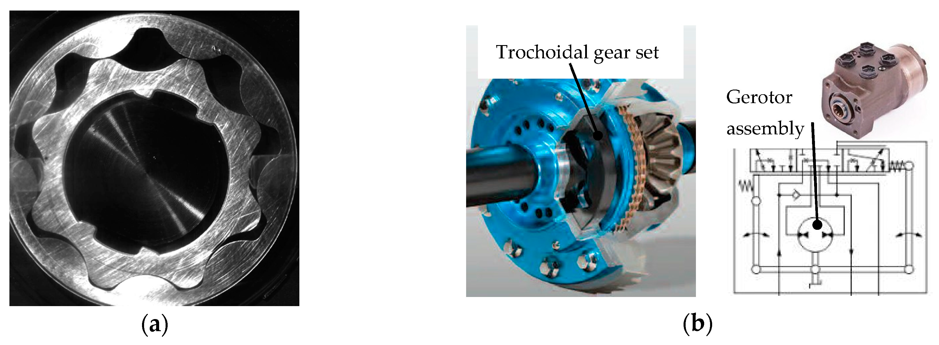
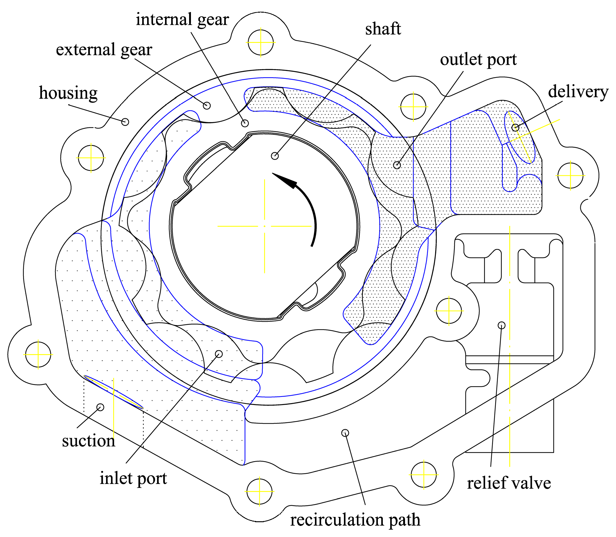
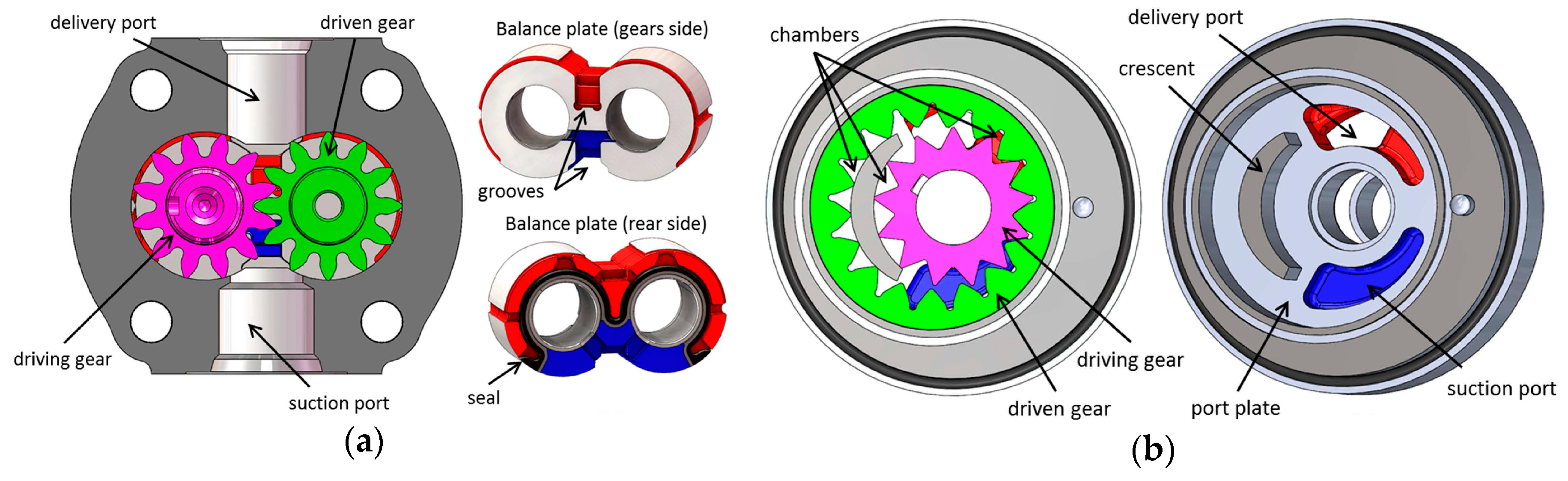
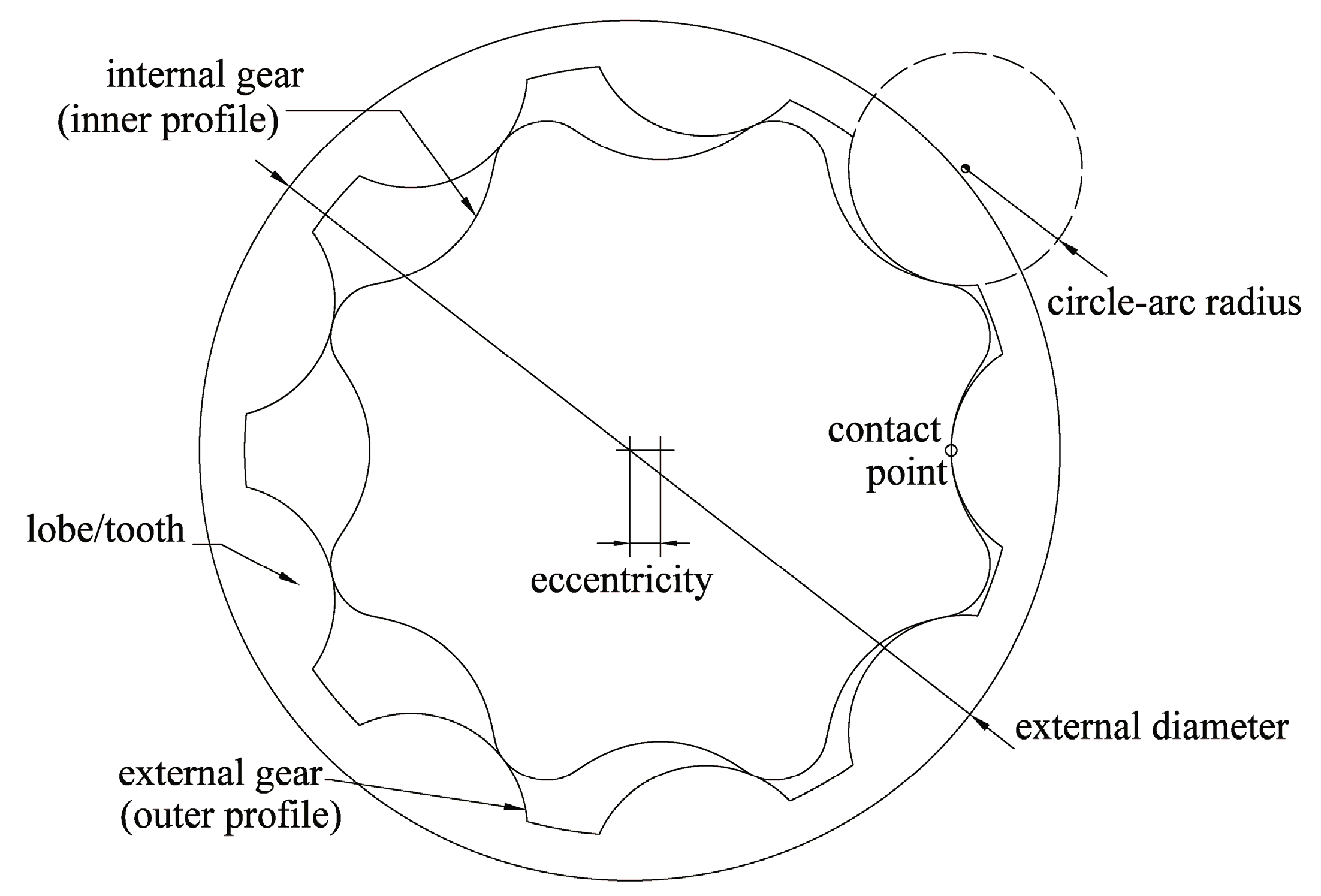
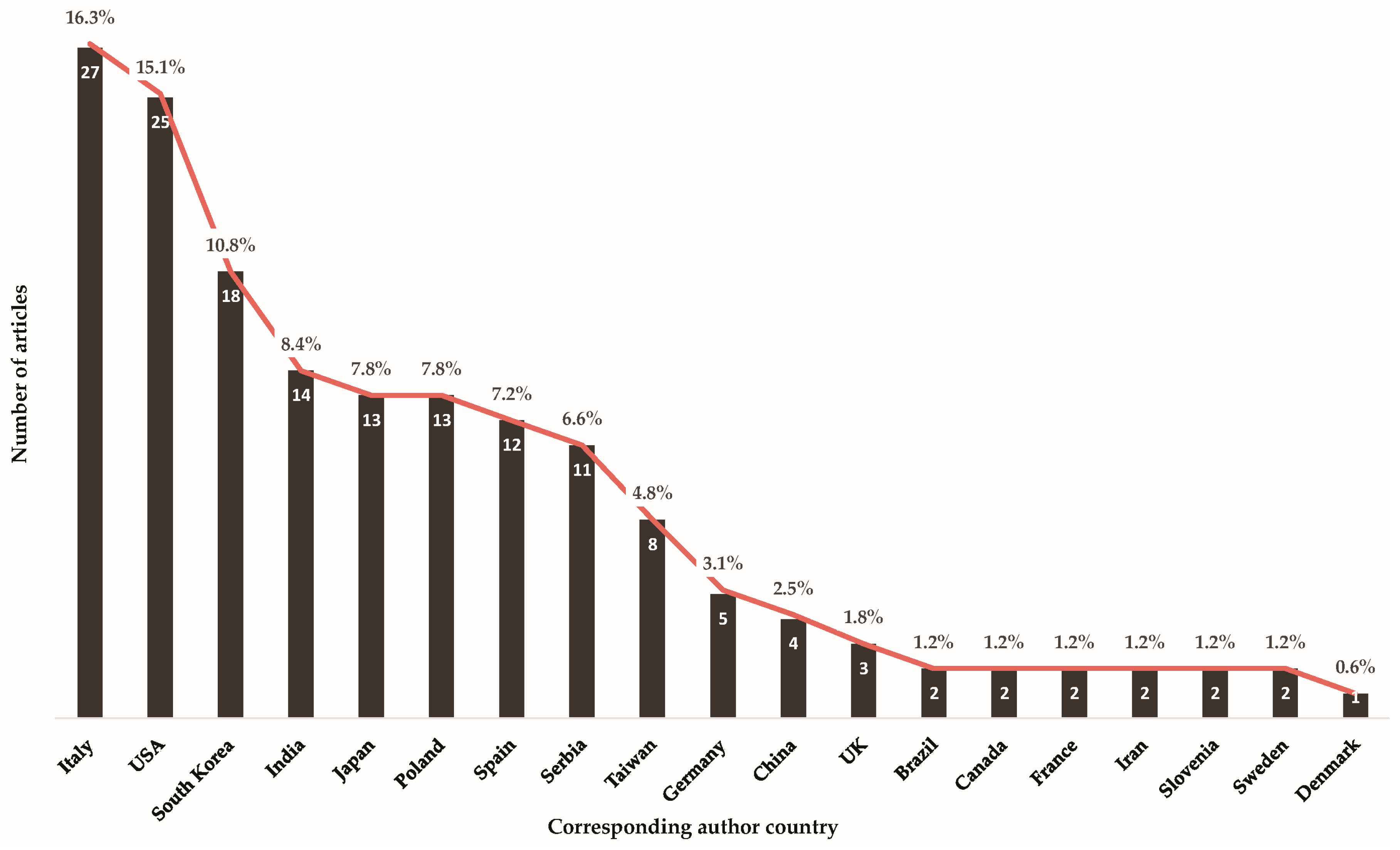
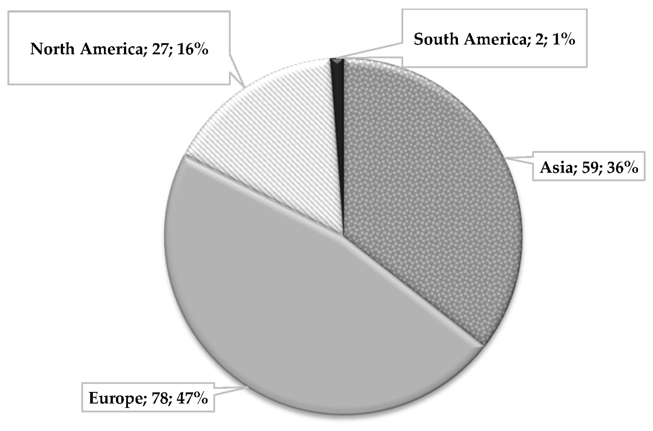
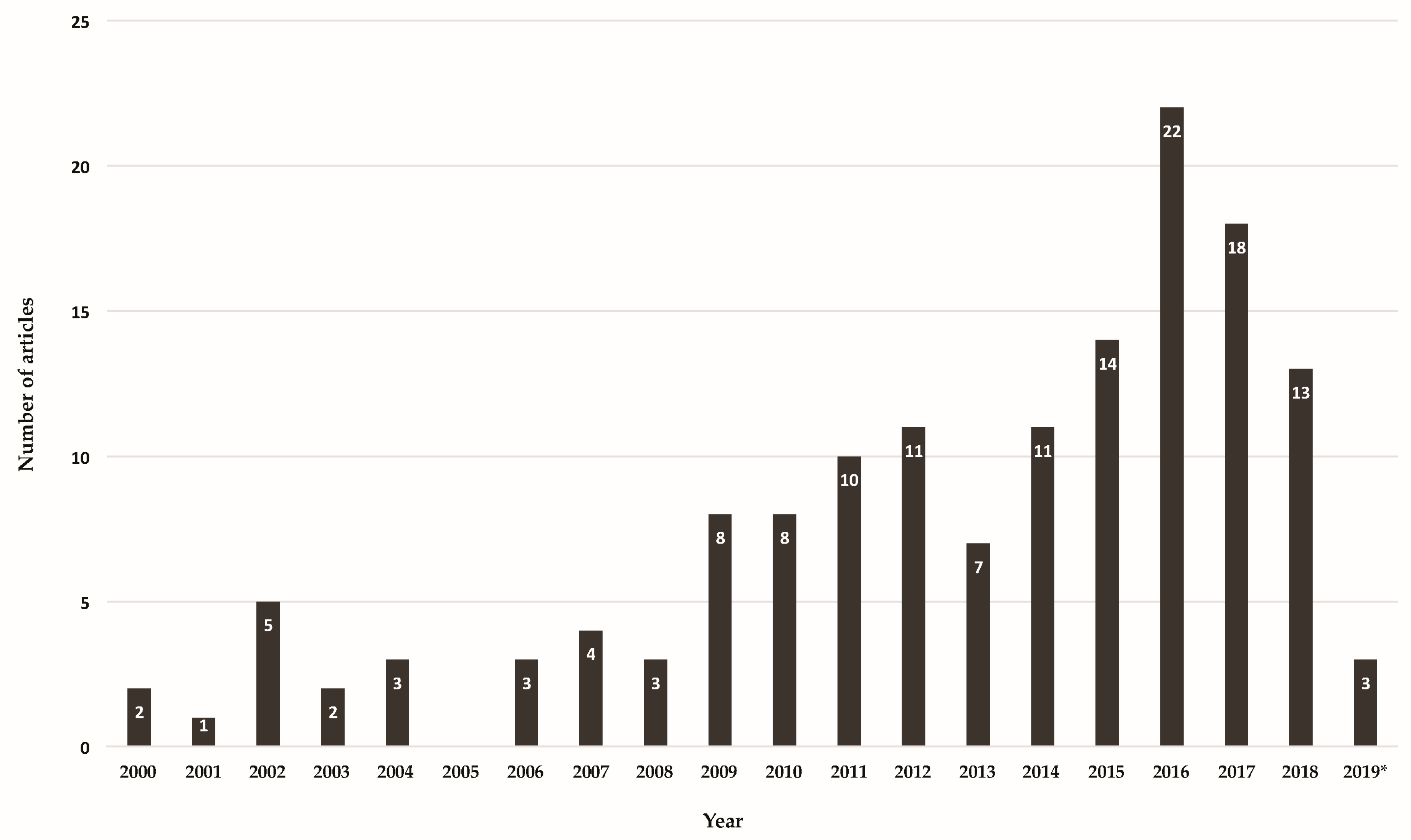
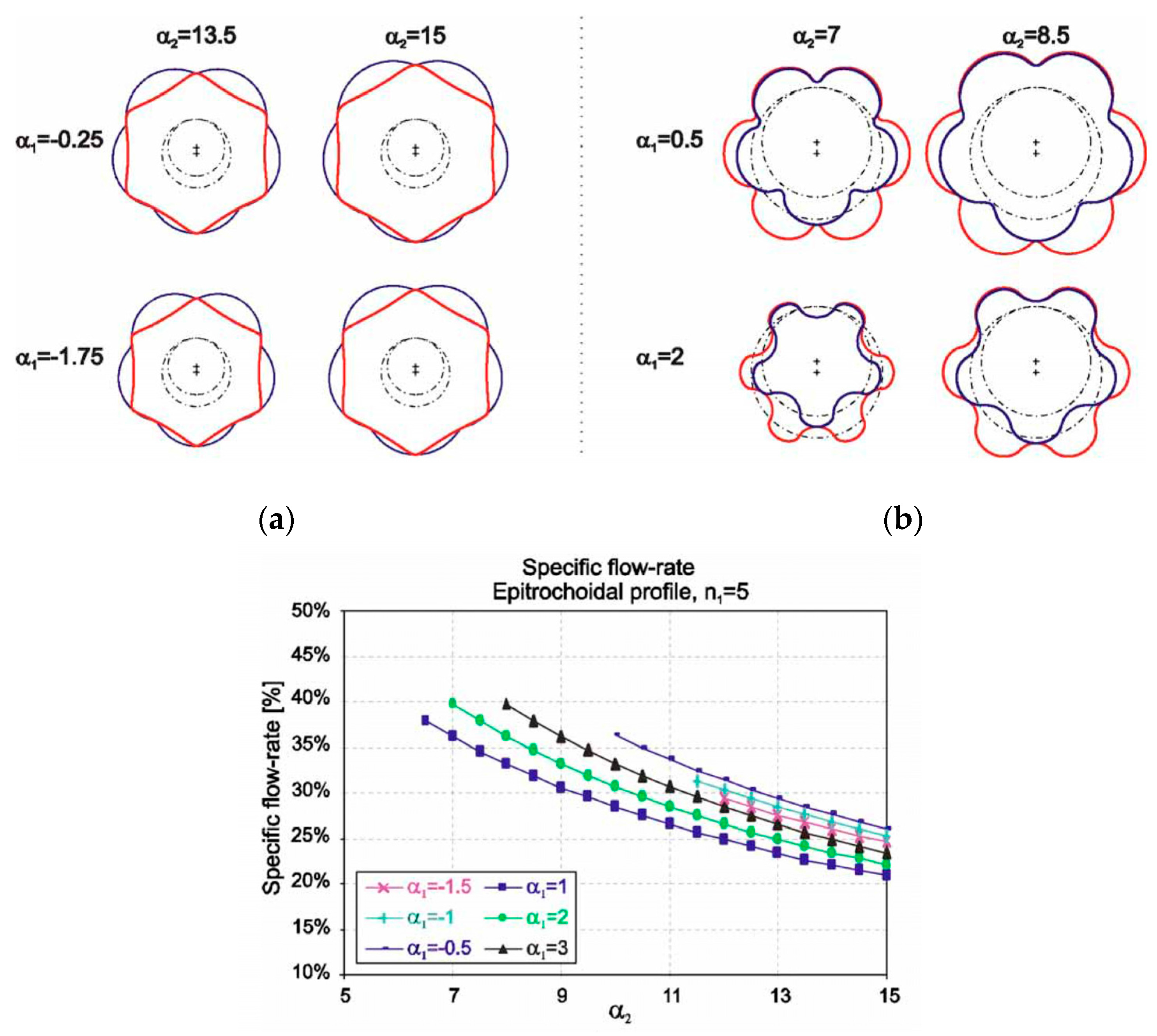
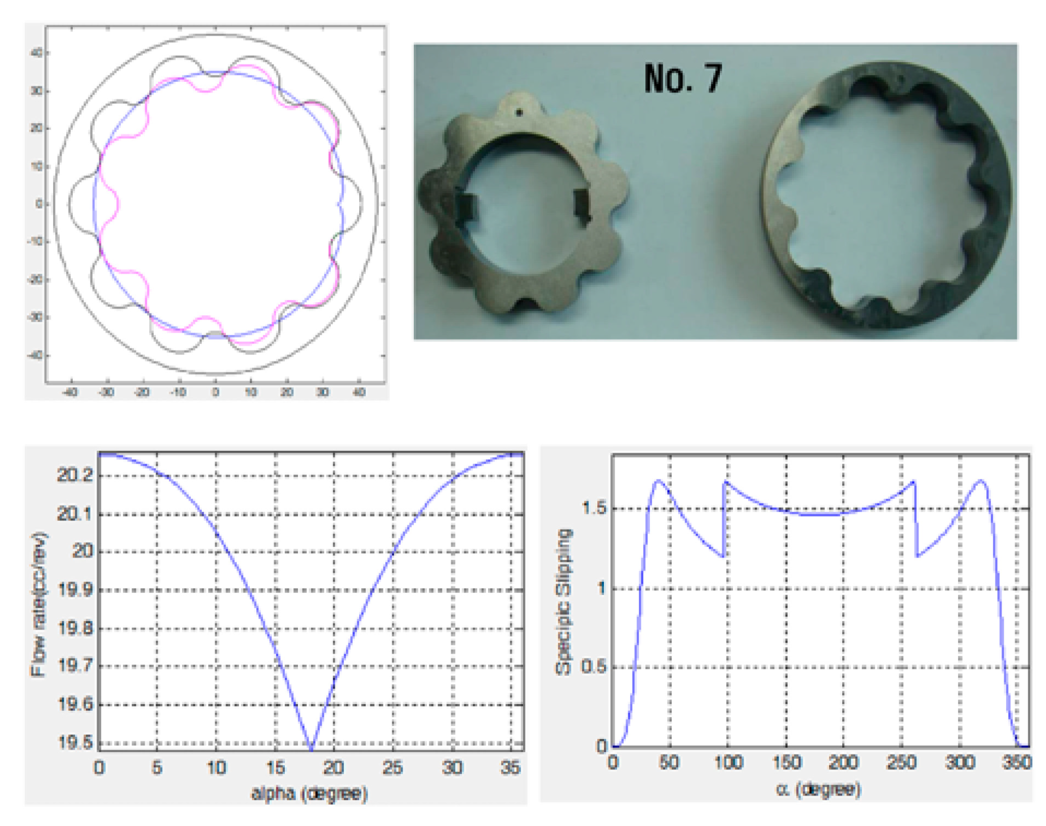
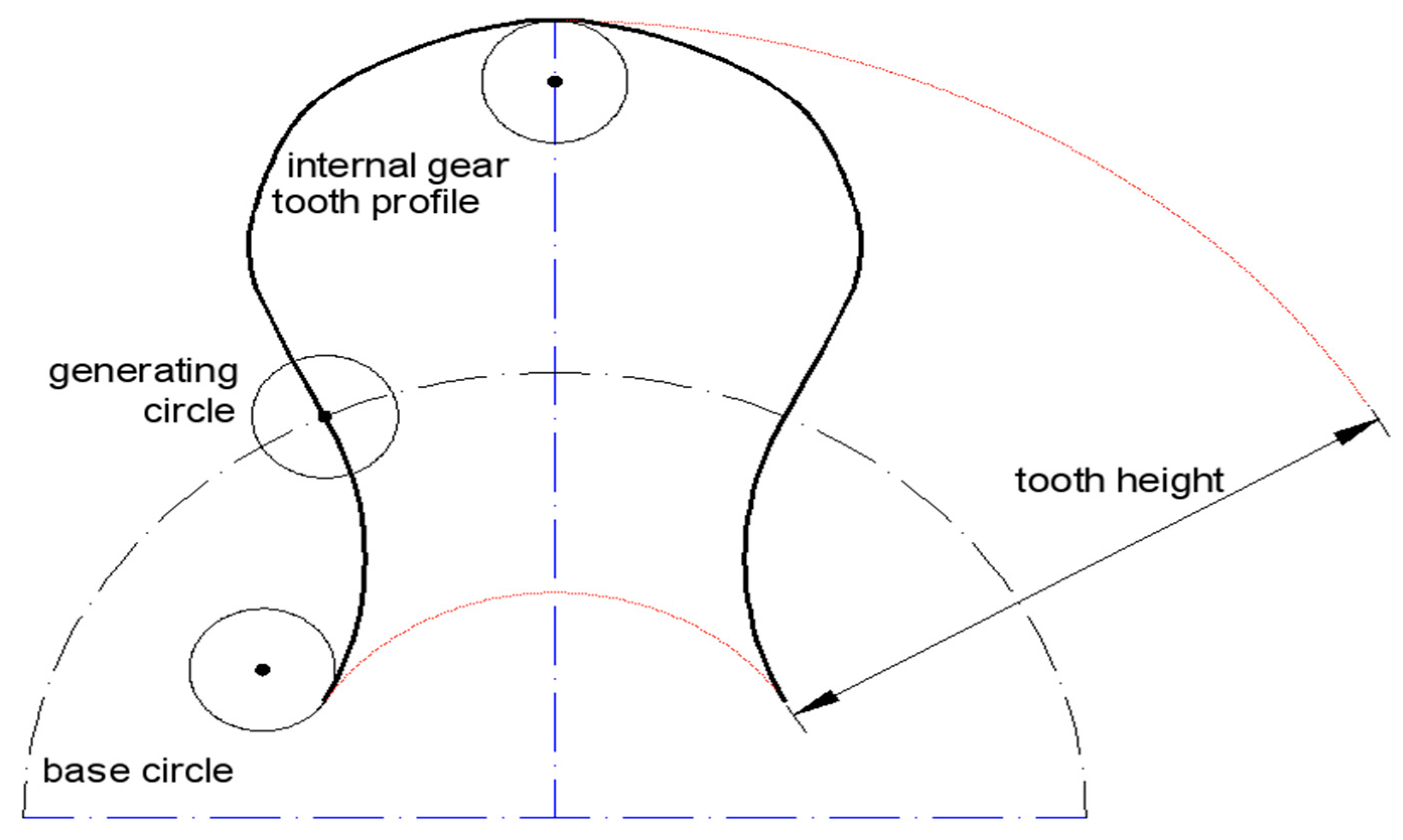
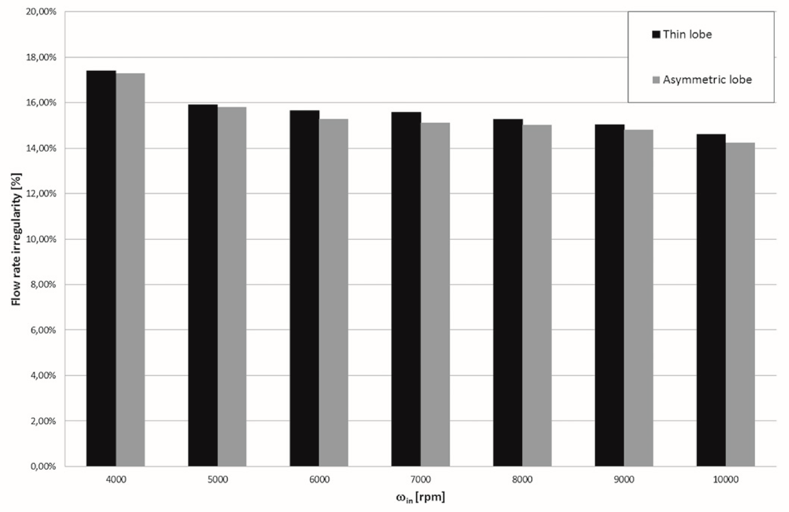
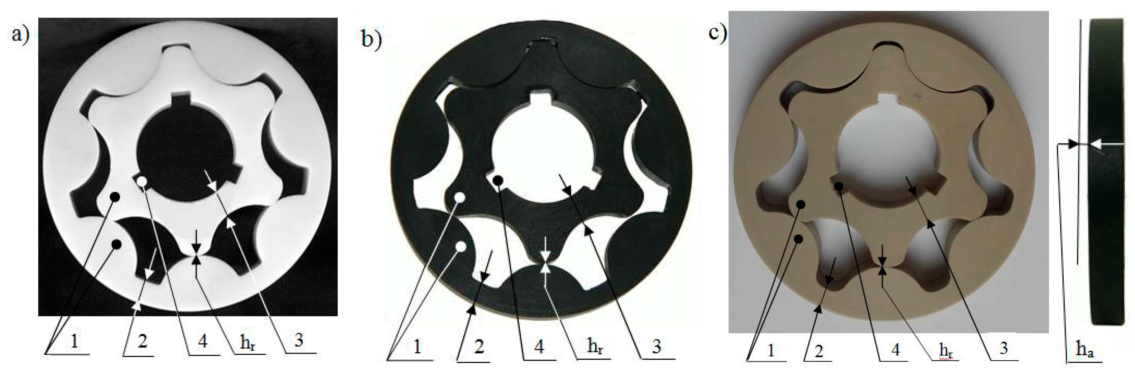
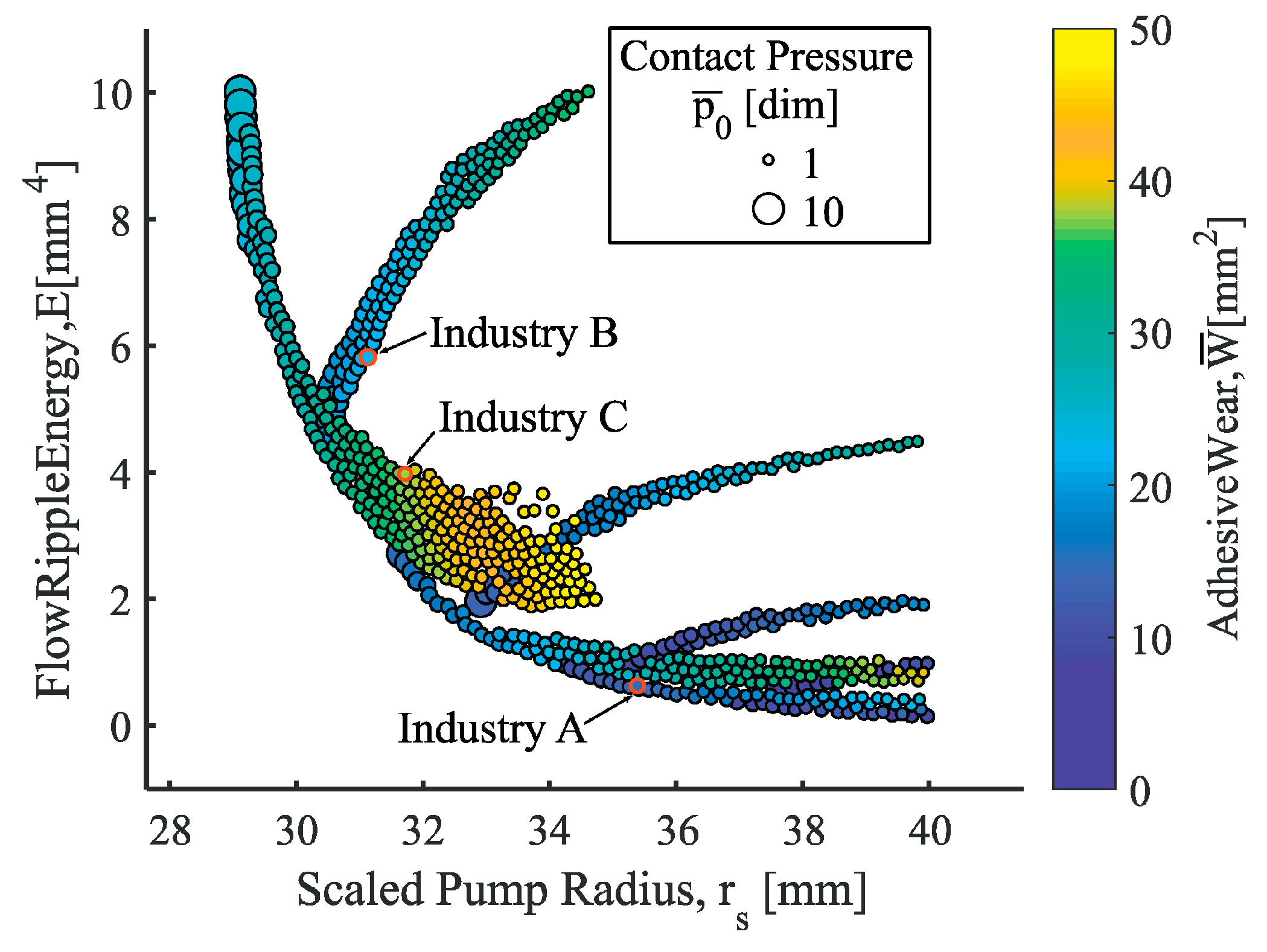
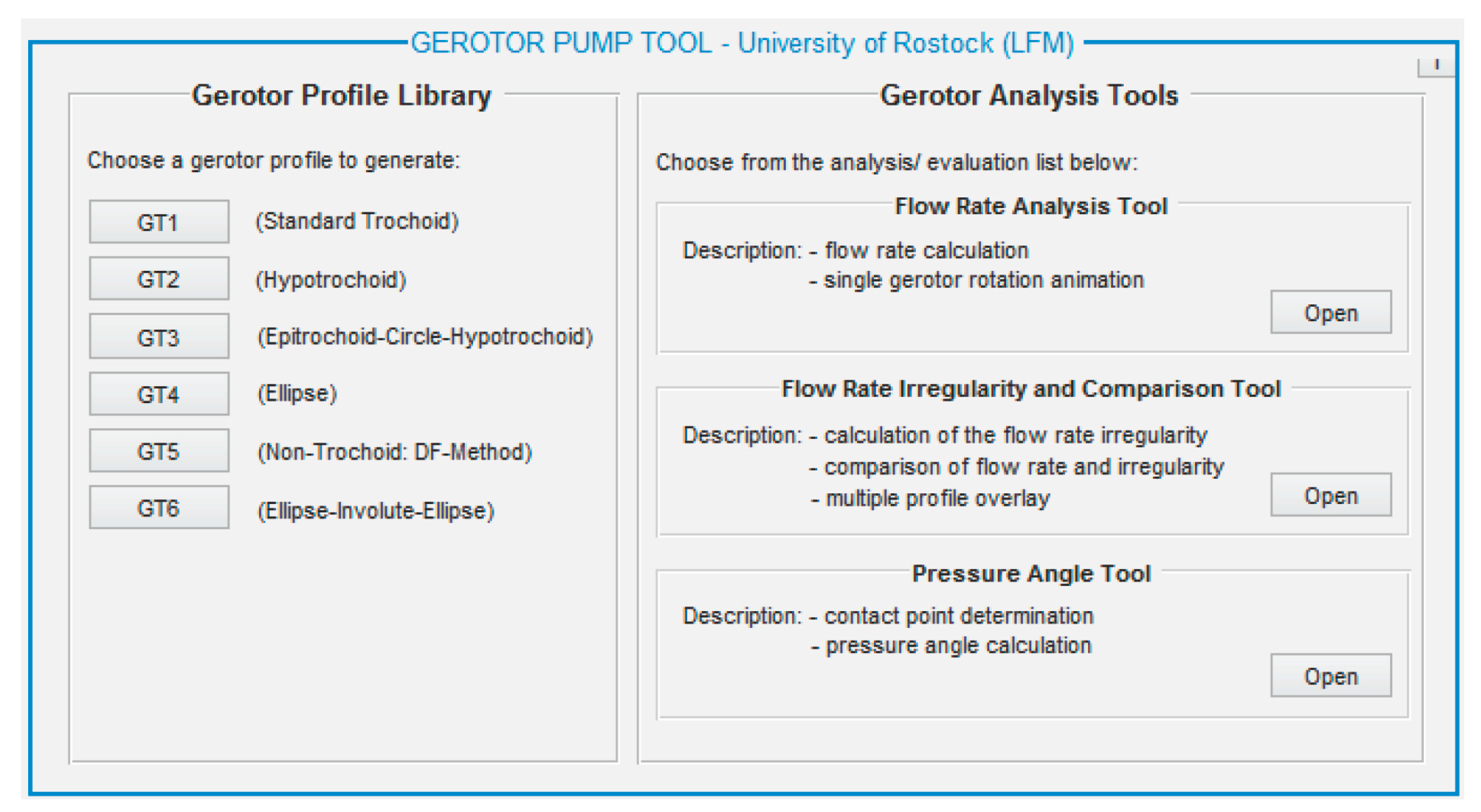
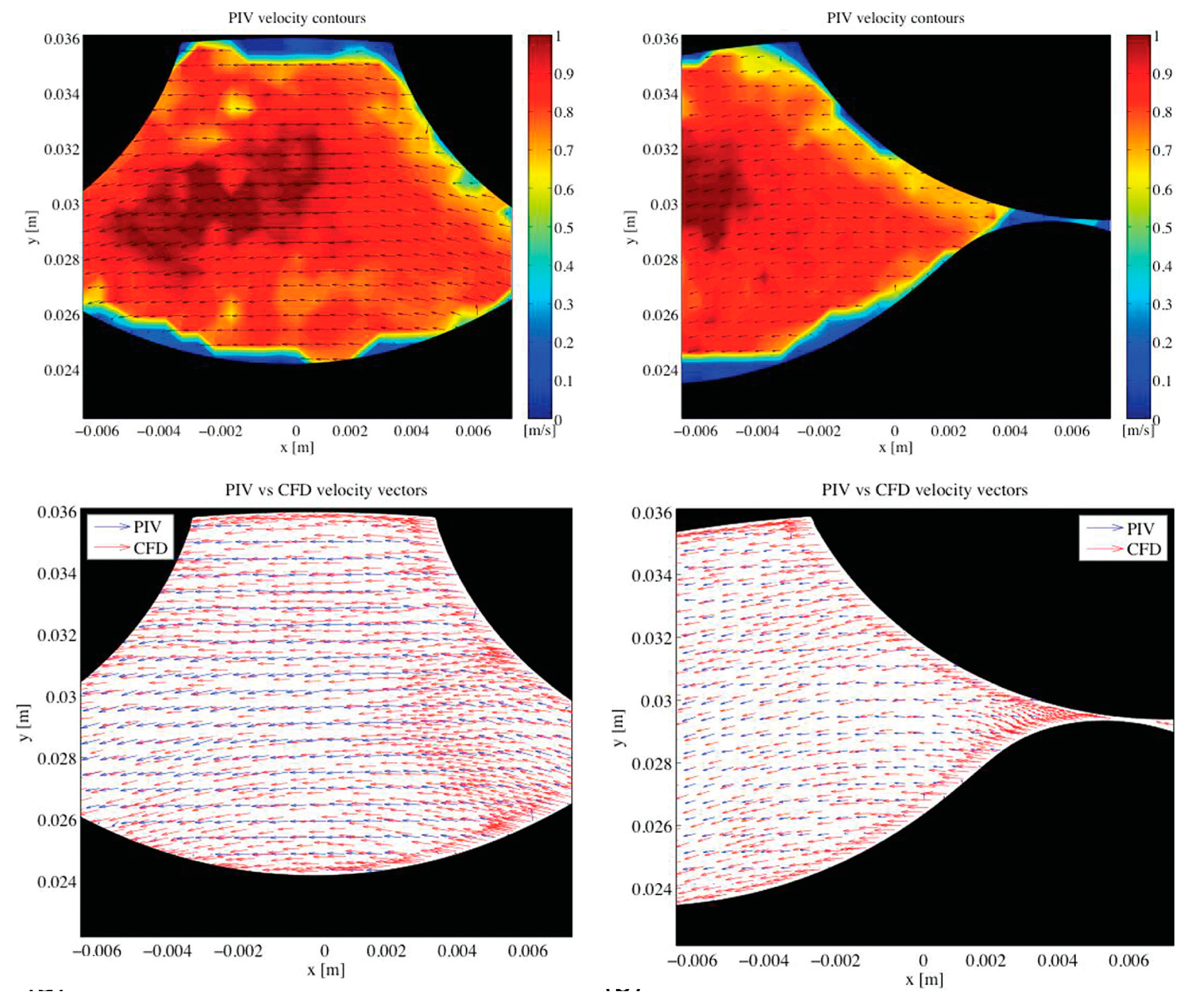
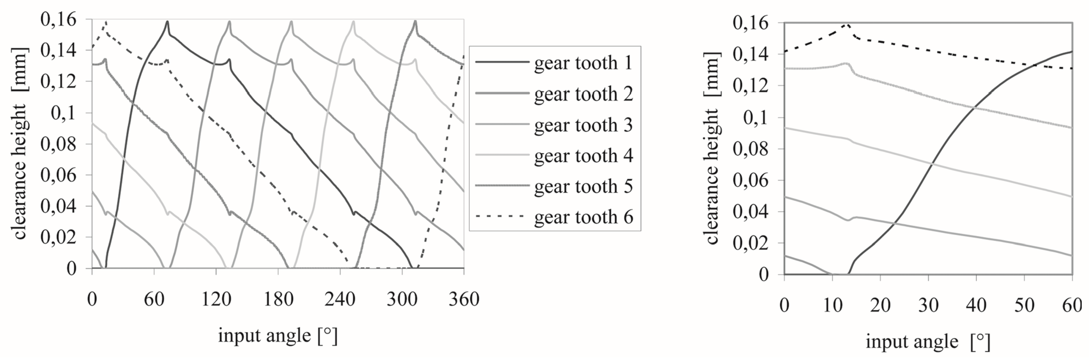
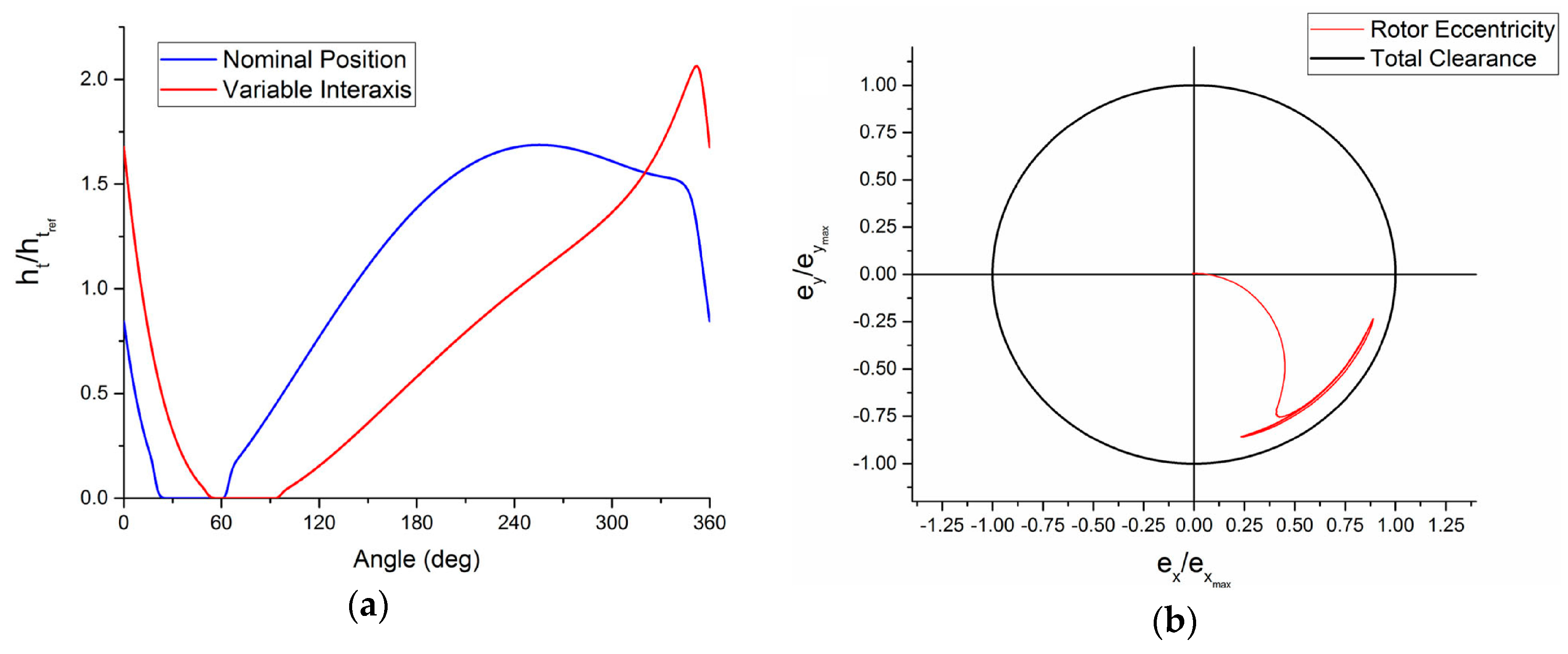
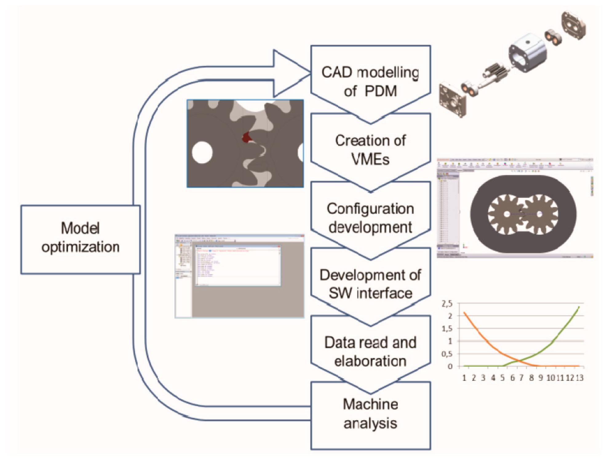
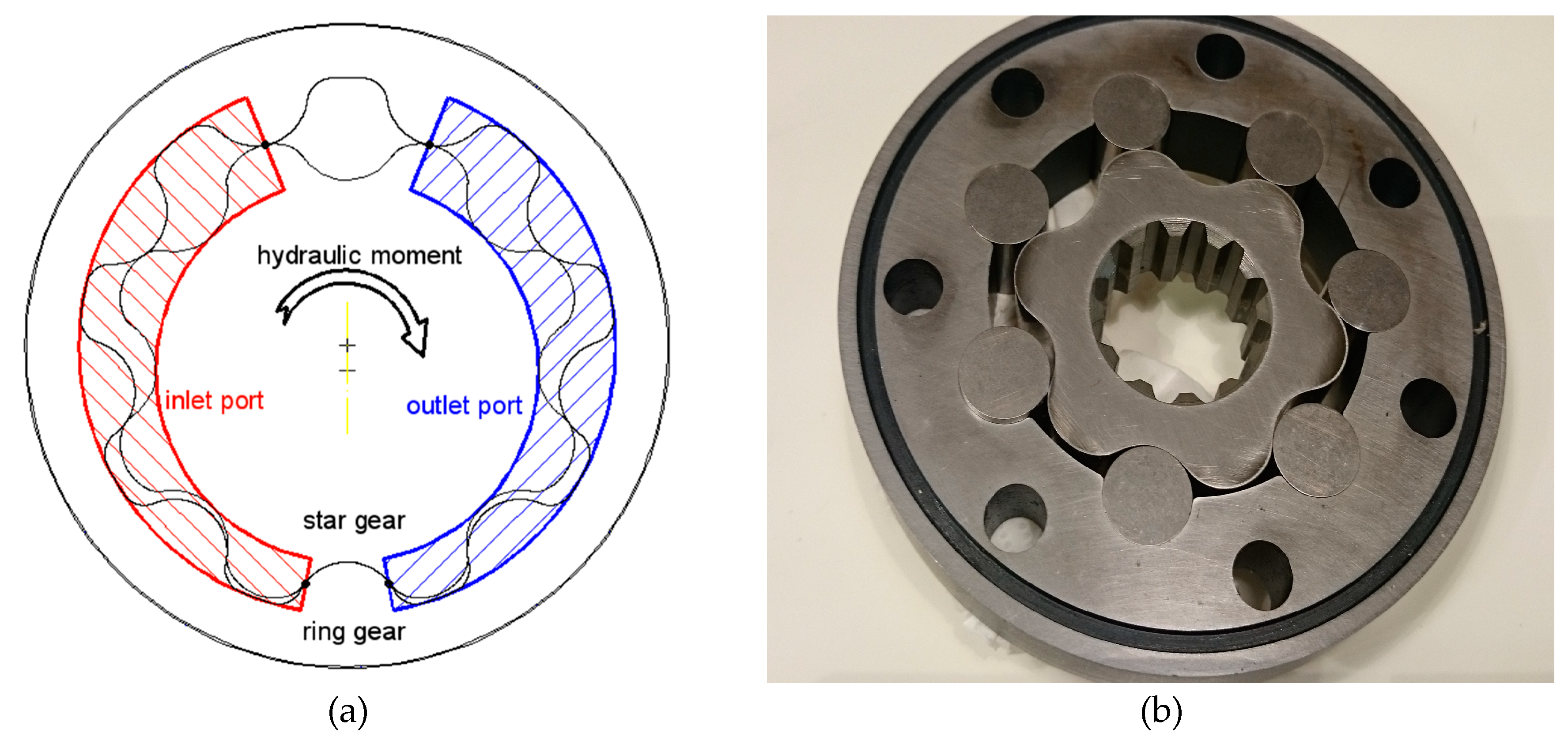
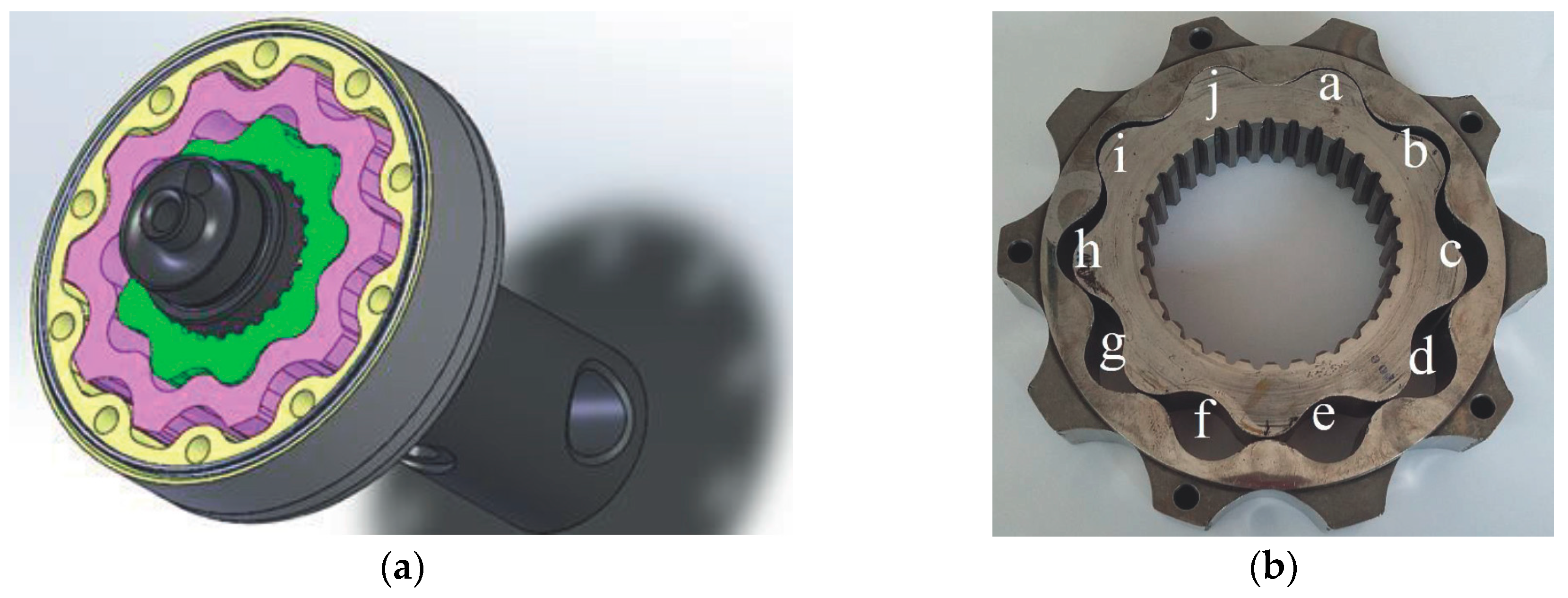
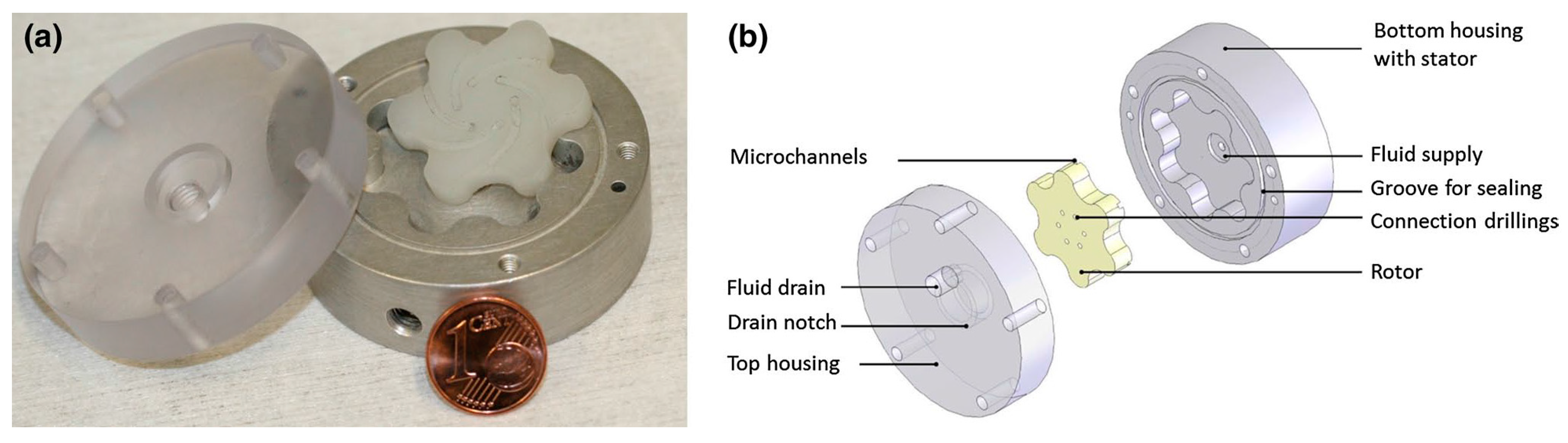
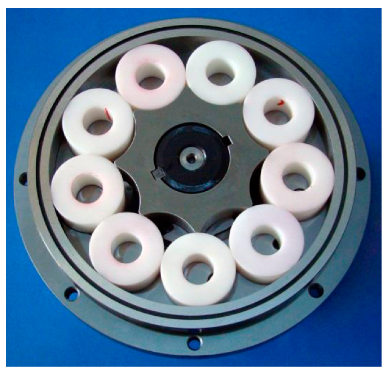
Table A1.
Chronological contribution in the reviewed literature.
| Decade | Year | Contribution | Ref. |
|---|---|---|---|
| 1960–1969 | |||
| 1968 | Historical Background | Ansdale and Lockley [5] | |
| 1970–1979 | |||
| 1974 | Historical Background | Colbourne [6] | |
| 1976 | Historical Background | Colbourne [7] | |
| Robinson and Lyon [8] | |||
| 1980–1989 | |||
| 1988 | Historical Background | Maiti and Sinha [12] | |
| 1990–1999 | |||
| 1990 | Historical Background | Maiti and Sinha [13] | |
| 1992 | Historical Background | Beard et al. [9] | |
| 1993 | Historical Background | Maiti [14] | |
| 1994 | Historical Background | Shung and Pennock [10] | |
| 1996 | Historical Background | Stryczek [11] | |
| Dasgupta et al. [15] | |||
| 1999 | Historical Background | Fabiani et al. [17] | |
| New Scales and Concepts | Harada et al. [156] | ||
| 2000–2009 | |||
| 2000 | Historical Background | Mimmi and Pennacchi [16] | |
| Manufacturing, Clearances and Porting | Mancò et al. [61] | ||
| 2001 | Historical Background | Vecchiato et al. [19] | |
| 2002 | Historical Background | Mancò et al. [18] | |
| Demenego et al. [20]. | |||
| Ivantysyn and Ivantysynova [24] | |||
| New Scales and Concepts | Harada et al. [157] | ||
| Mancò et al. [158] | |||
| 2003 | Historical Background | Paffoni [21] | |
| New Scales and Concepts | Huber and Aktaa [160] | ||
| 2004 | Historical Background | Paffoni et al. [22] | |
| Litvin [23] | |||
| Variable Flow Development | Mancò et al. [106] | ||
| 2006 | Manufacturing, Clearances and Porting | Kim et al. [62] | |
| Visualization Techniques | Itoh et al. [97] | ||
| New Scales and Concepts | Maruo and Inoue [162] | ||
| 2007 | Conventional Profiles | Hwang and Hsieh [28] | |
| Hsieh and Hwang [29] | |||
| Manufacturing, Clearances and Porting | Chen et al. [67] | ||
| Software Techniques | Chang et al. [89] | ||
| 2008 | High Efficiency Profiles | Sasaki et al. [41] | |
| Energy, Flow, Friction and Stress Indexes Evaluation | Kwon et al. [50] | ||
| Variable Flow Development | Toyoda et al. [105] | ||
| 2009 | Conventional Profiles | Bonandrini et al. [25] | |
| Hsieh [31] | |||
| 2009 | Unconventional Profiles | Tong et al. [34] | |
| Yan et al. [35] | |||
| Software Techniques | Gamez-Montero et al. [91] | ||
| Gamez-Montero et al. [92] | |||
| Fluid-dynamic Methods | Elayaraja et al. [132] | ||
| Hydraulic Orbital Motors | Michael et al. [150] | ||
| 2010–2014* | |||
| 2010 | Conventional Profiles | Known et al. [30] | |
| Bonandrini et al. [26] | |||
| Energy, Flow, Friction and Stress Indexes Evaluation | Rundo [44] | ||
| Ivanović et al. [51] | |||
| Manufacturing, Clearances and Porting | Hsieh [63] | ||
| Materials | Biernacki and Stryczek [73] | ||
| Visualization Techniques | Antoniak [98] | ||
| Fluid-dynamic Methods | Suresh Kumar and Manonmani [133] | ||
| 2011 | Unconventional Profiles | Yang et al. [36] | |
| Jung et al. [37] | |||
| Energy, Flow, Friction and Stress Indexes Evaluation | Meira et al. [45] | ||
| Inaguma [46] | |||
| Karamooz Ravari [55] | |||
| Optimization Techniques | Kwon et al. [82] | ||
| Software Techniques | Schweiger et al. [94] | ||
| CAD Methods | Kim et al. [127] | ||
| Fluid-dynamic Methods | Ruvalcaba and Hu [134] | ||
| Hydraulic Orbital Motors | Garcia [144] | ||
| 2012 | Conventional Profiles | Bonandrini et al. [27] | |
| Hsieh [32] | |||
| Unconventional Profiles | Choi et al. [38] | ||
| High Efficiency Profiles | Yoshida et al. [42] | ||
| Energy, Flow, Friction and Stress Indexes Evaluation | Inaguma [47] | ||
| Optimization Techniques | Karamooz Ravari et al. [83] | ||
| Software Techniques | Gamez-Montero et al. [93] | ||
| Analytical Methods | Ivanović et al. [110] | ||
| CAD Methods | Carconi et al. [128] | ||
| Fluid-dynamic Methods | Gamez-Montero et al. [135] | ||
| Hydraulic Orbital Motors | Ding et al. [145] | ||
| 2013 | Energy, Flow, Friction and Stress Indexes Evaluation | Inaguma [48] | |
| Manufacturing, Clearances and Porting | Jamadar et al. [65] | ||
| Analytical Methods | Ivanović et al. [111] | ||
| Ivanović et al. [112] | |||
| Fluid-dynamic Methods | Frosina et al. [136] | ||
| Hydraulic Orbital Motors | Nag and Maiti [146] | ||
| New Scales and Concepts | O’Sea et al. [165] | ||
| 2014 | Conventional Profiles | Liu et al. [33] | |
| Materials | Biernacki [74] | ||
| Stryczek et al. [75] | |||
| Stryczek et al. [77] | |||
| Krawczyk and Stryczek [78] | |||
| CAD Methods | Jeong et al. [126] | ||
| Prakash and Manjula [129] | |||
| Fluid-dynamic Methods | Frosina et al. [137] | ||
| New Scales and Concepts | Leester-Schädel et al. [161] | ||
| Malvasi et al. [163] | |||
| Heisel and Mishev [164] | |||
| 2015–2019* | |||
| 2015 | Unconventional Profiles | Bae and Kim [39] | |
| Manufacturing, Clearances and Porting | Hsieh [64] | ||
| Materials | Biernacki [76] | ||
| Software Techniques | Klopsch et al. [95] | ||
| Visualization Techniques | Stryczek et al. [99] | ||
| Garcia-Vilchez et al. [100] | |||
| Variable Flow Development | Avery and Johnston [109] | ||
| Integrated Methods | Frosina et al. [114] | ||
| Hussain et al. [115] | |||
| CAD Methods | Moetakef and Zouani [130] | ||
| Fluid-dynamic Methods | Hsieh [138] | ||
| Sang et al. [139] | |||
| Hydraulic Orbital Motors | Maiti et al. [147] | ||
| Furustig et al. [149] | |||
| 2016 | Unconventional Profiles | Hao et al. [40] | |
| High Efficiency Profiles | Arinaga et al. [43] | ||
| Energy, Flow, Friction and Stress Indexes Evaluation | Kamal et al. [49] | ||
| Ivanović [52] | |||
| Ivanović et al. [53] | |||
| Ivanović et al. [54] | |||
| Jacazio et al. [56] | |||
| Kwak et al. [57] | |||
| O’Shea [59] | |||
| Manufacturing, Clearances and Porting | Harrison et al. [66] | ||
| Kwak et al. [70] | |||
| Materials | Krawczyk and Stryczek [79] | ||
| Software Techniques | Bae et al. [90] | ||
| Visualization Techniques | Sahoo et al. [102] | ||
| Integrated Methods | Pellegri et al. [118] | ||
| Pellegri et al. [119] | |||
| Buono et al. [122] | |||
| CAD Methods | Gherardini et al. [131] | ||
| Fluid-dynamic Methods | Altare and Rundo [140] | ||
| Gamez-Montero et al. [142] | |||
| Hydraulic Orbital Motors | Bigliardi et al. [148] | ||
| Furustig et al. [151] | |||
| 2017 | Energy, Flow, Friction and Stress Indexes Evaluation | Siano et al. [60] | |
| Manufacturing, Clearances and Porting | Kwak et al. [71] | ||
| Materials | Stryczek et al. [80] | ||
| Mancini et at. [81] | |||
| Optimization Techniques | Ivanović et al. [84] | ||
| Ivanović et al. [85] | |||
| Software Techniques | Zhang et al. [96] | ||
| Visualization Techniques | Raush et al. [101] | ||
| Variable Flow Development | Yamamoto et al. [107] | ||
| Integrated Methods | Altare and Rundo [116] | ||
| Fangwei et al. [117] | |||
| Pellegri and Vacca [120] | |||
| Pellegri and Vacca [121] | |||
| Buono et al. [123] | |||
| Shah et al. [124] | |||
| Fluid-dynamic Methods | Castilla et al. [141] | ||
| New Scales and Concepts | Gamez-Montero et al. [159] | ||
| Gamez-Montero et al. [166] | |||
| 2018 | Energy, Flow, Friction and Stress Indexes Evaluation | Lee et al. [58] | |
| Manufacturing, Clearances and Porting | Ham et al. [68] | ||
| Sung et al. [69] | |||
| Gamez-Montero et al. [72] | |||
| Optimization Techniques | Robinson and Vacca [86] | ||
| Visualization Techniques | Antoniak and Stryczek [103] | ||
| Antoniak et al. [104] | |||
| Variable Flow Development | Nishida et al. [108] | ||
| Analytical Methods | Ivanović et al. [113] | ||
| Fluid-dynamic Methods | Gamez-Montero et al. [143] | ||
| Hydraulic Orbital Motors | Bates et al. [152] | ||
| Strmčnik and Majdič [153,154] | |||
| Zardin et al. [155] | |||
| 2019 | Optimization Techniques | Robinson and Vacca [87] | |
| De Martin et al. [88] | |||
| Integrated Methods | Singh et al. [125] |
Table A2.
Approaches in the reviewed literature.
| Approach | Contribution | Year | Ref. |
|---|---|---|---|
| Historical | |||
| Historical Background | 1968 | Ansdale and Lockley [5] | |
| 1974 | Colbourne [6] | ||
| 1976 | Colbourne [7] | ||
| Robinson and Lyon [8] | |||
| 1988 | Maiti and Sinha [12] | ||
| 1990 | Maiti and Sinha [13] | ||
| 1992 | Beard et al. [9] | ||
| 1993 | Maiti [14] | ||
| 1994 | Shung and Pennock [10] | ||
| 1996 | Stryczek [11] | ||
| Dasgupta et al. [15] | |||
| 1999 | Fabiani et al. [17] | ||
| 2000 | Mimmi and Pennacchi [16] | ||
| 2001 | Vecchiato et al. [19] | ||
| 2002 | Mancò et al. [18] | ||
| Demenego et al. [20]. | |||
| Ivantysyn and Ivantysynova [24] | |||
| 2003 | Paffoni [21] | ||
| 2004 | Paffoni et al. [22] | ||
| Litvin [23] | |||
| Geometric | |||
| Conventional Profiles | 2007 | Hwang and Hsieh [28] | |
| Hsieh and Hwang [29] | |||
| 2009 | Bonandrini et al. [25] | ||
| Hsieh [31] | |||
| 2010 | Known et al. [30] | ||
| Bonandrini et al. [26] | |||
| 2012 | Bonandrini et al. [27] | ||
| Hsieh [32] | |||
| 2015 | Liu et al. [33] | ||
| Unconventional Profiles | 2009 | Tong et al. [34] | |
| Yan et al. [35] | |||
| 2011 | Yang et al. [36] | ||
| Jung et al. [37] | |||
| 2012 | Choi et al. [38] | ||
| 2015 | Bae and Kim [39] | ||
| 2016 | Hao et al. [40] | ||
| High Efficiency Profiles | 2008 | Sasaki et al. [41] | |
| 2012 | Yoshida et al. [42] | ||
| 2016 | Arinaga et al. [43] | ||
| Performance | |||
| Energy, Flow, Friction and Stress Indexes Evaluation | 2008 | Kwon et al. [50] | |
| 2010 | Rundo [44] | ||
| Ivanović et al. [51] | |||
| 2011 | Meira et al. [45] | ||
| Inaguma [46] | |||
| Karamooz Ravari [55] | |||
| 2012 | Inaguma [47] | ||
| 2013 | Inaguma [48] | ||
| 2016 | Kamal et al. [49] | ||
| Ivanović [52] | |||
| Ivanović et al. [53] | |||
| Ivanović et al. [54] | |||
| Jacazio et al. [56] | |||
| Kwak et al. [57] | |||
| O’Shea [59] | |||
| 2017 | Siano et al. [60] | ||
| 2018 | Lee et al. [58] | ||
| Manufacturing, Clearances and Porting | 2000 | Mancò et al. [61] | |
| 2006 | Kim et al. [62] | ||
| 2007 | Chen et al. [67] | ||
| 2010 | Hsieh [63] | ||
| 2013 | Jamadar et al. [65] | ||
| 2015 | Hsieh [64] | ||
| 2016 | Harrison et al. [66] | ||
| Kwak et al. [70] | |||
| 2017 | Kwak et al. [71] | ||
| 2018 | Ham et al. [68] | ||
| Sung et al. [69] | |||
| Gamez-Montero et al. [72] | |||
| Materials | 2010 | Biernacki and Stryczek [73] | |
| 2014 | Biernacki [74] | ||
| Stryczek et al. [75] | |||
| Stryczek et al. [77] | |||
| Krawczyk and Stryczek [78] | |||
| 2015 | Biernacki [76] | ||
| 2016 | Krawczyk and Stryczek [79] | ||
| 2017 | Stryczek et al. [80] | ||
| Mancini et at. [81] | |||
| Optimization Techniques | 2011 | Kwon et al. [82] | |
| 2012 | Karamooz Ravari et al. [83] | ||
| 2017 | Ivanović et al. [84,85] | ||
| 2018 | Robinson and Vacca [86] | ||
| 2019 | Robinson and Vacca [87] | ||
| De Martin et al. [88] | |||
| Software Techniques | 2007 | Chang et al. [89] | |
| 2009 | Gamez-Montero et al. [91] | ||
| Gamez-Montero et al. [92] | |||
| 2011 | Schweiger et al. [94] | ||
| 2012 | Gamez-Montero et al. [93] | ||
| 2015 | Klopsch et al. [95] | ||
| 2016 | Bae et al. [90] | ||
| 2017 | Zhang et al. [96] | ||
| Visualization Techniques | 2006 | Itoh et al. [97] | |
| 2010 | Antoniak [98] | ||
| 2015 | Stryczek et al. [99] | ||
| Garcia-Vilchez et al. [100] | |||
| 2017 | Raush et al. [101] | ||
| 2016 | Sahoo et al. [102] | ||
| 2018 | Antoniak and Stryczek [103] | ||
| Antoniak et al. [104] | |||
| Variable Flow Development | 2004 | Mancò et al. [106] | |
| 2008 | Toyoda et al. [105] | ||
| 2015 | Avery and Johnston [109] | ||
| 2017 | Yamamoto et al. [107] | ||
| 2018 | Nishida et al. [108] | ||
| Modelling and Numerical Simulation | |||
| Analytical Methods | 2012 | Ivanović et al. [110] | |
| 2013 | Ivanović et al. [111,112] | ||
| 2018 | Ivanović et al. [113] | ||
| Integrated Methods | 2015 | Frosina et al. [114] | |
| Hussain et al. [115] | |||
| 2016 | Pellegri et al. [118,119] | ||
| Buono et al. [122] | |||
| 2017 | Altare and Rundo [116] | ||
| Fangwei et al. [117] | |||
| Pellegri and Vacca [120,121] | |||
| Buono et al. [123] | |||
| Shah et al. [124] | |||
| 2019 | Singh et al. [125] | ||
| CAD Methods | 2011 | Kim et al. [127] | |
| 2012 | Carconi et al. [128] | ||
| 2014 | Jeong et al. [126] | ||
| Prakash and Manjula [129] | |||
| 2015 | Moetakef and Zouani [130] | ||
| 2016 | Gherardini et al. [131] | ||
| Fluid-dynamic Methods | 2009 | Elayaraja et al. [132] | |
| 2010 | Suresh Kumar and Manonmani [133] | ||
| 2011 | Ruvalcaba and Hu [134] | ||
| 2012 | Gamez-Montero et al. [135] | ||
| 2013 | Frosina et al. [136] | ||
| 2014 | Frosina et al. [137] | ||
| 2015 | Hsieh [138] | ||
| Sang et al. [139] | |||
| 2016 | Altare and Rundo [140] | ||
| Gamez-Montero et al. [142] | |||
| 2017 | Castilla et al. [141] | ||
| 2018 | Gamez-Montero et al. [143] | ||
| Hydraulic Orbital Motors | Hydraulic Orbital Motors | 2009 | Michael et al. [150] |
| 2011 | Garcia [144] | ||
| 2012 | Ding et al. [145] | ||
| 2013 | Nag and Maiti [146] | ||
| 2015 | Maiti et al. [147] | ||
| Furustig et al. [149] | |||
| 2016 | Bigliardi et al. [148] | ||
| Furustig et al. [151] | |||
| 2018 | Bates et al. [152] | ||
| 2018 | Strmčnik and Majdič [153,154] | ||
| Zardin et al. [155] | |||
| New Scales and Concepts | New Scales and Concepts | 1999 | Harada et al. [156] |
| 2002 | Harada et al. [157] | ||
| Mancò et al. [158] | |||
| 2003 | Huber and Aktaa [160] | ||
| 2006 | Maruo and Inoue [162] | ||
| 2013 | O’Sea et al. [165] | ||
| 2014 | Leester-Schädel et al. [161] | ||
| 2014 | Malvasi et al. [163] | ||
| Heisel and Mishev [164] | |||
| 2017 | Gamez-Montero et al. [159] | ||
| Gamez-Montero et al. [166] |
References
- Rundo, M.; Nervegna, N. Lubrication Pumps for Internal Combustion Engines: A Review. Int. J. Fluid Power 2015, 16, 59–74. [Google Scholar] [CrossRef]
- Rundo, M. Models for flow rate simulation in gear pumps: A review. Energies 2017, 10, 1261. [Google Scholar] [CrossRef]
- Miladinović, S.; Ivanović, L.; Blagojević, M.; Stojanović, B. The development of magnetic gears for transportation applications. Mobil. Veh. Mech. 2017, 43, 41–55. [Google Scholar] [CrossRef]
- Vacca, A. Energy efficiency and controllability of fluid power systems. Energies 2018, 11, 1169. [Google Scholar] [CrossRef]
- Ansdale, R.F.; Lockley, D.J. The Wankel RC Engine Design and Performance; London Iliffe Books: London, UK, 1968. [Google Scholar]
- Colbourne, J.R. The geometry of trochoid envelopes and their application in rotary pumps. Mech. Mach. Theory 1974, 9, 421–435. [Google Scholar] [CrossRef]
- Colbourne, J.R. Reduction of contact stress in internal gear pumps. J. Eng. Ind. 1976, 98, 1296–1300. [Google Scholar] [CrossRef]
- Robinson, F.J.; Lyon, J.R. An analysis of epitrochoidal profiles with constant difference modification suitable for rotary expanders and pumps. J. Manuf. Sci. Eng. Trans. ASME 1976, 98, 161–165. [Google Scholar] [CrossRef]
- Beard, J.E.; Yannitell, D.W.; Pennock, G.R. The effects of the generating pin size and placement on the curvature and displacement of epitrochoidal gerotors. Mech. Mach. Theory 1992, 27, 373–389. [Google Scholar] [CrossRef]
- Shung, J.B.; Pennock, G.R. Geometry for trochoidal-type machines with conjugate envelopes. Mech. Mach. Sci. 1994, 29, 25–42. [Google Scholar] [CrossRef]
- Stryczek, J. Hydraulic machines with cycloidal gearing. Archiwum Budowy Maszyn 1996, 43, 29–71. [Google Scholar]
- Maiti, R.; Sinha, G.L. Kinematics of active contact in modified epitrochoid generated rotary piston machines. Mech. Mach. Theory 1988, 23, 39–45. [Google Scholar] [CrossRef]
- Maiti, R.; Sinha, G.L. Limits on modification of epitrochoid used in rotary piston machines and the effects of modification on geometric volume displacement and ripple. Ingenieur-Archiv 1990, 60, 183–194. [Google Scholar] [CrossRef]
- Maiti, R. Torque characteristics of epitrochoid generated orbital rotary piston type hydraulic motors. Mech. Mach. Theory 1993, 28, 225–231. [Google Scholar] [CrossRef]
- Dasgupta, K.; Mukherjee, A.; Maiti, R. Theoretical and experimental studies of the steady state performance of an orbital rotor low-speed high-torque hydraulic motor. Proc. Inst. Mech. Eng. A 1996, 210, 423–429. [Google Scholar] [CrossRef]
- Mimmi, G.C.; Pennacchi, P.E. Non-undercutting conditions in internal gears. Mech. Mach. Theory 2000, 35, 477–490. [Google Scholar] [CrossRef]
- Fabiani, M.; Mancò, S.; Nervegna, N.; Rundo, M. Modelling and simulation of gerotor gearing in lubricating oil pumps. SAE Trans. J. Engines 1999, 108, 989–1003. [Google Scholar]
- Mancò, S.; Nervegna, N.; Rundo, M. A contribution to the design of hydraulic lube pumps. Int. J. Fluid Power 2002, 3, 21–32. [Google Scholar] [CrossRef]
- Vecchiato, D.; Demenego, A.; Argyris, J.; Litvin, F.L. Geometry of a cycloidal pump. Comput. Methods Appl. Mech. Eng. 2001, 190, 2309–2330. [Google Scholar] [CrossRef]
- Demenego, A.; Vecchiato, D.; Litvin, F.L.; Nervegna, N.; Mancó, S. Design and simulation of meshing of a cycloidal pump. Mech. Mach. Theory 2002, 37, 311–332. [Google Scholar] [CrossRef]
- Paffoni, B. Pressure and film thickness in a trochoidal hydrostatic gear pump. Proc. Inst. Mech. Eng. G 2003, 217, 179–187. [Google Scholar] [CrossRef]
- Paffoni, B.; Progri, R.; Gras, R. Teeth clearance effects upon pressure and film thickness in a trochoidal hydrostatic gear pump. Proc. Inst. Mech. Eng. G 2004, 218, 247–256. [Google Scholar] [CrossRef]
- Litvin, F.L.; Fuentes, A. Gear Geometry and Applied Theory, 2nd ed.; Cambridge University Press: Cambridge, UK, 2004. [Google Scholar]
- Ivantysyn, J.; Ivantysynova, M. Hydrostatic Pumps and Motors, Principles, Designs, Performance, Modelling, Analysis, Control and Testing; Akademia Books International: New Delhi, India, 2002. [Google Scholar]
- Bonandrini, G.; Mimmi, G.; Rottenbacher, C. Theoretical analysis of internal epitrochoidal and hypotrochoidal machines. Proc. Inst. Mech. Eng. C 2009, 223, 1469–1480. [Google Scholar] [CrossRef]
- Bonandrini, G.; Mimmi, G.; Rottenbacher, C. Theoretical Analysis of an Original Rotary Machine. J. Mech. Des. 2010, 132, 024501. [Google Scholar] [CrossRef]
- Bonandrini, G.; Mimmi, G.; Rottenbacher, C. Design and simulation of meshing of a particular internal rotary pump. Mech. Mach. Theory 2012, 49, 104–116. [Google Scholar] [CrossRef]
- Hwang, Y.-W.; Hsieh, C.-F. Geometric design using hypotrochoid and nonundercutting conditions for an internal cycloidal gear. J. Mech. Des. 2007, 129, 413–420. [Google Scholar] [CrossRef]
- Hsieh, C.-F.; Hwang, Y.-W. Geometric design for a gerotor pump with high area efficiency. J. Mech. Des. 2007, 129, 1269–1277. [Google Scholar] [CrossRef]
- Kwon, S.-M.; Kang, H.S.; Shin, J.-H. Rotor profile design in a hypogerotor pump. J. Mech. Sci. Technol. 2010, 23, 3459–3470. [Google Scholar] [CrossRef]
- Hsieh, C.-F. Influence of gerotor performance in varied geometrical design parameters. J. Mech. Des. 2009, 131, 121008. [Google Scholar] [CrossRef]
- Hsieh, C.F. Fluid and dynamics analyses of a gerotor pump using various span angle designs. J. Mech. Des. 2012, 134, 121003. [Google Scholar] [CrossRef]
- Liu, H.; Lee, J.-C.; Yoon, A.; Kim, S.-T. Profile design and numerical calculation of instantaneous flow rate of a gerotor pump. J. Appl. Math. Phys. 2015, 3, 92–97. [Google Scholar] [CrossRef]
- Tong, S.-H.; Yan, J.; Yang, D.C.H. Design of deviation-function based gerotors. Mech. Mach. Theory 2009, 44, 1595–1606. [Google Scholar] [CrossRef]
- Yan, J.; Yang, D.C.H.; Tong, S.H. A new gerotor design method with switch angle assignability. J. Mech. Des. 2009, 131, 239–246. [Google Scholar] [CrossRef]
- Yang, D.C.H.; Yan, J.; Tong, S.-H. Flowrate formulation and displacement analyses for deviation function-based gerotor pumps. Proc. Inst. Mech. Eng. C 2011, 225, 480–487. [Google Scholar] [CrossRef]
- Jung, S.-Y.; Bae, J.-H.; Kim, M.-S.; Kim, C. Development of a new gerotor for oil pumps with multiple profiles. Int. J. Precis. Eng. Manuf. 2011, 12, 835–841. [Google Scholar] [CrossRef]
- Choi, T.H.; Kim, M.S.; Lee, G.S.; Jung, S.Y.; Bae, J.H.; Kim, C. Design of rotor for internal gear pump using cycloid and circular-arc curves. J. Mech. Des. 2012, 134, 011005. [Google Scholar] [CrossRef]
- Bae, J.-H.; Kim, C. Design of rotor profile of internal gear pump for improving fuel efficiency. Int. J. Precis. Eng. Manuf. 2015, 16, 113–120. [Google Scholar] [CrossRef]
- Hao, C.; Wenming, Y.; Guangming, L. Design of gerotor oil pump with new rotor profile for improving performance. Proc. Inst. Mech. Eng. C 2016, 230, 592–601. [Google Scholar] [CrossRef]
- Sasaki, H.; Inui, N.; Shimada, Y.; Ogata, D. Development of High Efficiency P/M Internal Gear Pump Rotor (Megafloid Rotor). SEI Tech. Rev. 2008, 66, 124–128. [Google Scholar]
- Yoshida, K.; Uozumi, M.; Shimada, Y.; Kosuge, T. Development of Continuously Variable Discharge Oil Pump. SEI Tech. Rev. 2012, 74, 43–47. [Google Scholar]
- Arinaga, S.; Yoshida, K.; Takada, S.; Noda, M.; Inoue, K. The latest trends in oil pump rotors for automobiles. SEI Tech. Rev. 2016, 82, 59–65. [Google Scholar]
- Rundo, M. Energy Consumption in ICE Lubricating Gear Pumps; SAE Technical Paper; SAE International: Warrendale, PA, USA, 2010. [Google Scholar] [CrossRef]
- Meira, J.; Filho, A.; Melo, W.; Ribeiro, E. Strategies for Energy Savings with Use of Constant and Variable Oil Pump Systems; SAE Technical Papers 2011-36-0150; SAE International: Warrendale, PA, USA, 2011; pp. 1–6. [Google Scholar] [CrossRef]
- Inaguma, Y. Friction torque characteristics of an internal gear pump. Proc. Inst. Mech. Eng. C 2011, 225, 1523–1534. [Google Scholar] [CrossRef]
- Inaguma, Y. Oil temperature influence on friction torque characteristics in hydraulic pumps. Proc. Inst. Mech. Eng. C 2012, 226, 2267–2280. [Google Scholar] [CrossRef]
- Inaguma, Y. A practical approach for analysis of leakage flow characteristics in hydraulic pumps. Proc. Inst. Mech. Eng. C 2013, 227, 980–991. [Google Scholar] [CrossRef]
- Kamal, A.; Kaundabalaraman, K.; Rathi, H.; Muley, A. Design Analysis & Parametric Optimization of Gerotor Oil Pump for Improving Volumetric Efficiency; SAE Technical Papers 2016-28-0113; SAE International: Warrendale, PA, USA, 2016; pp. 1–10. [Google Scholar] [CrossRef]
- Kwon, S.-M.; Kim, C.-H.; Shin, J.-H. Analytical wear model of a gerotor pump without hydrodynamic effect. J. Adv. Mech. Des. Syst. Manuf. 2008, 2, 230–237. [Google Scholar] [CrossRef]
- Ivanović, L.; Devedžić, G.; Mirić, N.; Ćuković, S. Analysis of forces and moments in gerotor pumps. Proc. Inst. Mech. Eng. C 2010, 224, 2257–2269. [Google Scholar] [CrossRef]
- Ivanović, L. Reduction of the maximum contact stresses by changing geometric parameters of the trochoidal gearing teeth profile. Meccanica 2016, 51, 2243–2257. [Google Scholar] [CrossRef]
- Ivanović, L.; Rakić, B.; Stojanović, B.; Matejić, M. Comparative analysis of analytical and numerical calculations of contact stresses at rotational elements of gerotor pumps. Appl. Eng. Lett. 2016, 1, 1–7. [Google Scholar]
- Ivanović, L.; Mackić, T.; Stojanović, B. Analysis of the instantaneous friction coefficient of the trochoidal gear pair. J. Balk. Tribol. Assoc. 2016, 22, 281–293. [Google Scholar]
- Karamooz Ravari, M.R. Elliptical lobe shape gerotor pump design to minimize wear. Front. Mech. Eng. 2011, 6, 429–434. [Google Scholar] [CrossRef]
- Jacazio, G.; De Martin, A. Influence of rotor profile geometry on the performance of an original low-pressure gerotor pump. Mech. Mach. Theory 2016, 100, 296–312. [Google Scholar] [CrossRef]
- Kwak, H.-S.; Li, S.-H.; Kim, C. Optimal design of the gerotor (2-ellipses) for reducing maximum contact stress. J. Mech. Sci. Technol. 2016, 30, 5595–5603. [Google Scholar] [CrossRef]
- Lee, M.-C.; Kwak, H.-S.; Seong, H.-S.; Kim, C. A Study on Theoretical Flowrate of Gerotor Pump Using Chamber Areas. Int. J. Precis. Eng. Manuf. 2018, 19, 1385–1392. [Google Scholar] [CrossRef]
- O’Shea, C. Hydraulic Flow Ripple Cancellation Using the Primary Flow Source. In Proceedings of the BATH/ASME 2016 Symposium on Fluid Power and Motion Control, American Society of Mechanical Engineers, Bath, UK, 7–9 September 2016. [Google Scholar] [CrossRef]
- Siano, D.; Frosina, E.; Senatore, A. Diagnostic Process by Using Vibrational Sensors for Monitoring Cavitation Phenomena in a Getoror Pump Used for Automotive Applications. Energy Procedia 2017, 126, 1115–1122. [Google Scholar] [CrossRef]
- Mancò, S.; Nervegna, N.; Rundo, M. Effects of Timing and Odd/Even Number of Teeth on Noise Generation of Gerotor Lubricating Pumps for IC Engines; SAE Technical Papers 2000-01-2630; SAE International: Warrendale, PA, USA, 2000; pp. 109–118. [Google Scholar] [CrossRef]
- Kim, S.-Y.; Nam, Y.-J.; Park, M.-K. Design of port plate in gerotor pump for reduction of pressure pulsation. J. Mech. Sci. Technol. 2006, 20, 1626–1637. [Google Scholar] [CrossRef]
- Hsieh, C.-F. Non-undercutting region and property evaluation of epitrochoidal gerotor geometry. Proc. Inst. Mech. Eng. C 2010, 224, 473–481. [Google Scholar] [CrossRef]
- Hsieh, C.F. Flow characteristics of gerotor pumps with novel variable clearance designs. J. Fluid. Eng. 2015, 137, 041107. [Google Scholar] [CrossRef]
- Jamadar, M.; Jose, A.; Ramdasi, S.S.; Marathe, N.V. Development of In-House Competency to Build Compact Gerotor Oil Pump for High Speed Diesel Engine Application; SAE Technical Papers 2013-01-2738; SAE International: Warrendale, PA, USA, 2013; pp. 1–13. [Google Scholar] [CrossRef]
- Harrison, J.; Aihara, R.; Eisele, F. Modeling Gerotor Oil Pumps in 1D to Predict Performance with Known Operating Clearances. SAE Int. J. Engines 2016, 9, 1839–1846. [Google Scholar] [CrossRef]
- Chen, T.-T.; Wang, J.-P.; Huang, G.-M.; Hsu, M.-H.; Chen, C.-L.; Hong, B.-W.; Wey, J.-M. High-precision technology with negative punch clearance for the manufacturing of a cycloid pump. Int. J. Adv. Manuf. Technol. 2007, 95, 1179–1183. [Google Scholar] [CrossRef]
- Ham, J.; Kim, S.; Oh, J.; Cho, H. Theoretical investigation of the effect of a relief groove on the performance of a gerotor oil pump. J. Mech. Sci. Technol. 2018, 32, 3687–3698. [Google Scholar] [CrossRef]
- Sung, H.-J.; Min, H.-K.; Nam, Y.-J.; Park, M.-K. Design and experimental verification of a port plate in a gerotor pump to reduce pressure pulsation. J. Mech. Sci. Technol. 2018, 32, 671–678. [Google Scholar] [CrossRef]
- Kwak, H.-S.; Li, S.-H.; Kim, C. Performance improvement of an oil pump: Design of port assembled with gerotor (2-ellipses-combined lobe). Int. J. Precis. Eng. Manuf. 2016, 17, 1017–1024. [Google Scholar] [CrossRef]
- Kwak, H.; Kim, C. Design of port shape for reducing irregularity of oil pump. J. Mech. Sci. Technol. 2017, 31, 5839–5848. [Google Scholar] [CrossRef]
- Gamez-Montero, P.J.; Castilla, R.; Codina, E. Methodology based on best practice rules to design a new-born trochoidal-gear pump. Proc. Inst. Mech. Eng. C 2018, 232, 1057–1068. [Google Scholar] [CrossRef]
- Biernacki, K.; Stryczek, J. Analysis of stress and deformation in plastic gears used in gerotor pumps. J. Strain Anal. Eng. Des. 2010, 45, 465–479. [Google Scholar] [CrossRef]
- Biernacki, K. Selection of the optimum tooth profile for plastic cycloidal gears. Proc. Inst. Mech. Eng. C 2014, 228, 3395–3404. [Google Scholar] [CrossRef]
- Stryczek, J.; Bednarczyk, S.; Biernacki, K. Strength analysis of the polyoxymethylene cycloidal gears of the gerotor pump. Arch. Civ. Mech. Eng. 2014, 14, 647–660. [Google Scholar] [CrossRef]
- Biernacki, K. Analysis of the material and design modifications influence on strength of the cycloidal gear system. Int. J. Adv. Manuf. Technol. 2015, 16, 537–546. [Google Scholar] [CrossRef]
- Stryczek, J.; Bednarczyk, S.; Biernacki, K. Gerotor pump with POM gears: Design, production technology, research. Arch. Civ. Mech. Eng. 2014, 14, 391–397. [Google Scholar] [CrossRef]
- Krawczyk, J.; Stryczek, J. Construction and experimental research on plastic cycloidal gears used in gerotor pumps. In Proceedings of the 8th FPNI Ph.D Symposium on Fluid Power, Lappeenranta, Finland, 11–13 June 2014. [Google Scholar] [CrossRef]
- Krawczyk, J.; Stryczek, J. Designing of the gerotor pump body made of plastics. In Proceedings of the 9th FPNI Ph.D Symposium on Fluid Power, Florianópolis, SC, Brazil, 26–28 October 2016. [Google Scholar] [CrossRef]
- Stryczek, J.; Banaś, M.; Krawczyk, J.; Marciniak, L.; Stryczek, P. The fluid power elements and systems made of plastics. Procedia Eng. 2017, 176, 600–609. [Google Scholar] [CrossRef]
- Mancini, S.D.; Santos Neto, A.D.O.; Cioffi, M.O.H.; Bianchi, E.C. Replacement of metallic parts for polymer composite materials in motorcycle oil pumps. J. Reinf. Plast. Compos. 2017, 36, 149–160. [Google Scholar] [CrossRef]
- Kwon, S.-M.; Kim, C.-H.; Shin, J.-H. Optimal rotor wear design in hypotrochoidal gear pump using genetic algorithm. J. Cent. South Univ. Technol. 2011, 18, 718–725. [Google Scholar] [CrossRef]
- Karamooz Ravari, M.R.; Forouzan, M.R.; Moosavi, H. Flow irregularity and wear optimization in epitrochoidal gerotor pumps. Meccanica 2012, 47, 917–928. [Google Scholar] [CrossRef]
- Ivanović, L.T.; Veličković, S.N.; Stojanović, B.Ž.; Kandeva, M.; Jakimovska, K. The selection of optimal parameters of gerotor pump by application of factorial experimental design. FME Trans. 2017, 45, 159–164. [Google Scholar] [CrossRef] [Green Version]
- Ivanović, L.; Stojanović, B.; Blagojević, J.; Bogdanović, G.; Marinković, A. Analysis of the flow rate and the volumetric efficiency of the trochoidal pump by application of Taguchi method. Tehnicki Vjesnik 2017, 24, 265–270. [Google Scholar] [CrossRef] [Green Version]
- Robison, A.; Vacca, A. Multi-objective optimization of circular-toothed gerotors for kinematics and wear by genetic algorithm. Mech. Mach. Theory 2018, 128, 150–168. [Google Scholar] [CrossRef]
- Robinson, A.; Vacca, A. Multi-Objective Optimization of Gerotor Port Design by Genetic Algorithm with Considerations on Kinematic vs. Actual Flow Ripple; SAE Technical Papers 2019-01-0827; SAE International: Warrendale, PA, USA, 2019; in press. [Google Scholar]
- De Martin, A.; Jacazio, G.; Sorli, M. Optimization of gerotor pumps with asymmetric profiles through evolutionary strategy algorithm. Machines 2019, 7, 17. [Google Scholar] [CrossRef]
- Chang, Y.J.; Kim, J.H.; Jeon, C.H.; Kim, C.; Jung, S.Y. Development of an integrated system for the automated design of a gerotor oil pump. J. Mech. Des. 2007, 129, 1099–1105. [Google Scholar] [CrossRef]
- Bae, J.; Kwak, H.; San, S.; Kim, C. Design and CFD analysis of gerotor with multiple profiles (ellipse–involute–ellipse type and 3-ellipses type) using rotation and translation algorithm. Proc. Inst. Mech. Eng. C 2016, 230, 804–823. [Google Scholar] [CrossRef]
- Gamez-Montero, P.J.; Castilla, R.; Mujal, R.; Khamashta, M.; Codina, E. GEROLAB package system: Innovative tool to design a trochoidal-gear pump. J. Mech. Des. 2009, 131, 074502. [Google Scholar] [CrossRef]
- GeroLAB Package System. Available online: http://www.gerolab.es (accessed on 22 February 2019).
- Gamez-Montero, P.J.; Garcia-Vilchez, M.; Raush, G.; Freire, J.; Codina, E. Teeth Clearance and Relief Grooves Effects in a Trochoidal-Gear Pump Using New Modules of GeroLAB. J. Mech. Des. 2012, 134, 054502. [Google Scholar] [CrossRef]
- Schweiger, W.; Schoefmann, W.; Vacca, A. Gerotor Pumps for Automotive Drivetrain Applications: A Multi Domain Simulation Approach. SAE Int. J. Passeng. Cars 2011, 4, 1358–1376. [Google Scholar] [CrossRef]
- Klopsch, V.; Germann, T.; Seitz, H. Numerical simulation of low-pulsation gerotor pumps for use in the pharmaceutical industry and in biomedicine. Curr. Direct. Biomed. Eng. 2015, 1, 433–436. [Google Scholar] [CrossRef] [Green Version]
- Zhang, E.; Chen, M.; Deng, B. Parametric Design on Internal Gear of Cycloid Gear Pump with NX10.0. IOP Conf. Ser. Mater. Sci. Eng. 2017, 250, 1–5. [Google Scholar] [CrossRef]
- Itoh, Y.; Murai, Y.; Ueno, Y.; Oiwa, H.; Miyagi, N.; Yamamoto, F. Visualization of Internal Flow in an Inscribed Trochoid Gear Pump. Trans. Vis. Soc. Jpn. 2006, 26, 27–32. [Google Scholar] [CrossRef] [Green Version]
- Antoniak, P. Application of the PIV method to optimization of the internal channels of gerotor pumps. In Proceedings of the 7th International Fluid Power Conference, Aachen, Germany, 22–24 March 2010. [Google Scholar]
- Stryczek, J.; Antoniak, P.; Jakhno, O.; Kostyuk, D.; Kryuchkov, A.; Belov, G.; Rodionov, L. Visualisation research of the flow processes in the outlet chamber–outlet bridge–inlet chamber zone of the gear pumps. Arch. Civ. Mech. Eng. 2015, 15, 95–108. [Google Scholar] [CrossRef]
- Garcia-Vilchez, M.; Gamez-Montero, P.J.; Codina, E.; Castilla, R.; Raush, G.; Freire, J.; Rio, C. Computational fluid dynamics and particle image velocimetry assisted design tools for a new generation of trochoidal gear pumps. Adv. Mech. Eng. 2015, 7. [Google Scholar] [CrossRef] [Green Version]
- Raush, G.; Gamez-Montero, P.J.; Castilla, R.; Codina, E. Experimental study on the impulsion port of a trochoidal wheeled pump. Flow Meas. Instrum. 2017, 55, 13–22. [Google Scholar] [CrossRef]
- Sahoo, V.; Mukherjee, U.; Das, M.K.; Maiti, R.; Antoniak, P.; Stryczek, J.; Rodionov, L. Visualization of leakage flow through active contacts in toothed external gear pumps—CFD and photo imaging techniques. J. Flow Vis. Image Process. 2016, 23, 345–376. [Google Scholar] [CrossRef]
- Antoniak, P.; Stryczek, J. Visualization study of the flow processes and phenomena in the external gear pump. Arch. Civ. Mech. Eng. 2018, 18, 1103–1115. [Google Scholar] [CrossRef]
- Antoniak, P.; Stryczek, J.; Banas, M.; Lyhovskyi, O.; Gryshko, I.; Zilinskyi, A.; Kovalov, V. Visualization research on the influence of an ultrasonic degassing system on the operation of a hydraulic gear pump. MATEC Web Conf. 2018, 211, 03005. [Google Scholar] [CrossRef]
- Toyoda, F.; Kobayashi, Y.; Miura, Y.; Koga, Y. Development of Variable Discharge Oil Pump; SAE Technical Papers 2008-04-14; SAE International: Warrendale, PA, USA, 2008; pp. 1–6. [Google Scholar] [CrossRef]
- Mancò, S.; Nervegna, N.; Rundo, M.; Armenio, G. Displacement vs. Flow Control in IC Engines Lubricating Pumps; SAE Technical Papers 2004-01-1602; SAE International: Warrendale, PA, USA, 2004; pp. 1–9. [Google Scholar] [CrossRef]
- Yamamoto, M.; Hosogi, T.; Watanabe, T.; Nishida, Y. Development of Engine Lubrication System with New Internal Gear Fully Variable Discharge Oil Pump. SAE Int. J. Fuels Lubr. 2017, 10, 1–9. [Google Scholar] [CrossRef]
- Nishida, Y.; Toyoda, F.; Terashima, H.; Ono, H.; Nunami, K. Development of Continuously Variable Discharge Oil Pump; SAE Technical Papers 2018-01-0932; SAE International: Warrendale, PA, USA, 2018; pp. 1–7. [Google Scholar] [CrossRef]
- Avery, N.; Johnston, N. Variable Displacement Gear and Gerotor Pumps. In Proceedings of the ASME/BATH 2015 Symposium on Fluid Power and Motion Control, Chicago, IL, USA, 12–14 October 2015. [Google Scholar] [CrossRef]
- Ivanović, L.; Devedžić, G.; Ćuković, S.; Mirić, N. Modeling of the Meshing of Trochoidal Profiles with Clearances. J. Mech. Des. 2012, 134, 041003. [Google Scholar] [CrossRef]
- Ivanović, L.; Josifović, D.; Ilić, A. Modelling of trochoidal gearing at the gerotor pump. Mech. Mach. Sci. 2013, 13, 553–562. [Google Scholar] [CrossRef]
- Ivanović, L.; Josifović, D.; Ilić, A.; Stojanović, B. Analytical model of the pressure variation in the gerotor pump chambers. Tech. Technol. Educ. Manag. 2013, 8, 323–331. [Google Scholar]
- Ivanović, L.; Ilić, A.; Miloradović, D.; Josifović, D. Modelling and simulation of the load in the epicyclic rotary pump with trochoidal gear profiles. IOP Conf. Ser. Mater. Sci. Eng. 2018, 393, 1–9. [Google Scholar] [CrossRef]
- Frosina, E.; Senatore, A.; Buono, D.; Santato, L. Analysis and simulation of an oil lubrication pump for internal combustion engines. J. Fluids Eng. 2015, 137, 051102. [Google Scholar] [CrossRef]
- Hussain, T.; Sivaramakrishna, M.; Suresh Kumar, S.P. In-House Development of Gerotor Pump for Lubrication System of a Gas Turbine Engine. In Proceedings of the ASME 2015 Gas Turbine India Conference, Hyderabad, India, 2–3 December 2015. [Google Scholar] [CrossRef]
- Altare, G.; Rundo, M. Computational Fluid Dynamics Analysis of Gerotor Lubricating Pumps at High Speed: Geometric Features Influencing the Filling Capability. J. Fluid Eng. 2017, 138, 111101. [Google Scholar] [CrossRef]
- Fangwei, X.; Rui, X.; Gang, S.; Cuntang, W. Flow characteristics of accelerating pump in hydraulic-type wind power generation system under different wind speeds. Int. J. Adv. Manuf. Technol. 2017, 92, 189–196. [Google Scholar] [CrossRef]
- Pellegri, M.; Vacca, M.; Frosina, E.; Buono, D.; Senatore, A. Numerical analysis and experimental validation of Gerotor pumps: A comparison between a lumped parameter and a computational fluid dynamics-based approach. Proc. Inst. Mech. Eng. C 2016, 231, 4413–4430. [Google Scholar] [CrossRef] [Green Version]
- Pellegri, M.; Vacca, A.; Devendran, R.; Dautry, E.; Ginsberg, B. A Lumped Parameter Approach for GEROTOR Pumps: Model Formulation and Experimental Validation. In Proceedings of the 10th International Fluid Power Conference, Dresden, Germany, 8–10 March 2016. [Google Scholar]
- Pellegri, M.; Vacca, A. A simulation approach for the evaluation of power losses in the axial gap of gerotor units. In Proceedings of the 10th JFPS International Symposium on Fluid Power, Fukuoka, Japan, 24–27 October 2017. [Google Scholar]
- Pellegri, M.; Vacca, A. Numerical simulation of Gerotor pumps considering rotor micro-motions. Meccanica 2017, 52, 1851–1870. [Google Scholar] [CrossRef]
- Buono, D.; Schiano di Cola, F.D.; Senatore, A.; Frosina, E.; Buccilli, G.; Harrison, J. Modelling approach on a Gerotor pump working in cavitation conditions. Energy Procedia 2016, 101, 701–709. [Google Scholar] [CrossRef]
- Buono, D.; Siano, D.; Frosina, E.; Senatore, A. Gerotor pump cavitation monitoring and fault diagnosis using vibration analysis through the employment of auto-regressive-moving-average technique. Simul. Model. Pract. Theory 2017, 71, 61–82. [Google Scholar] [CrossRef]
- Shah, Y.G.; Vacca, A.; Dabiri, S.; Frosina, E. A fast lumped parameter approach for the prediction of both aeration and cavitation in Gerotor pumps. Meccanica 2017, 53, 175–191. [Google Scholar] [CrossRef] [Green Version]
- Singh, R.; Salutagi, S.S.; Piotr, P.; Madhavan, J. Study of Effect of Air Content in Lubrication Oil on Gerotor Pump Performance Using CFD Simulations; SAE Technical Papers 2019-26-0300; SAE International: Warrendale, PA, USA, 2019; pp. 1–5. [Google Scholar] [CrossRef]
- Jeong, S.W.; Chung, W.J.; Kim, M.S.; Kim, M.S. Application of SolidWorks® & AMESim®—Based Updated Simulation Technique to Back-flow Analysis of Trochoid Hydraulic Pump for Lubrication. In Proceedings of the 2014 World Congress in Computer Science, Computer Engineering and Applied Computing, Las Vegas, NV, USA, 21–24 July 2014. [Google Scholar]
- Kim, M.S.; Chung, W.J.; Jung, C.D.; Park, S.S.; Ahn, H.C.; Kim, H.C. On new methodology of AMESim® & CATIA® V5—Based cavitation simulation for flow rate control of trochoid hydraulic pump. In Proceedings of the 2011 International Conference on Mechatronics and Automation, Beijing, China, 7–10 August 2011. [Google Scholar] [CrossRef]
- Carconi, G.; D’Arcano, C.; Nervegna, N.; Rundo, M. Geometric Features of Gerotor Pumps: Analytic vs. CAD Methods. In Proceedings of the Bath/ASME Symposium on Fluid Power and Motion Control, Bath, UK, 12–14 September 2012. [Google Scholar]
- Prakash, H.R.; Manjula, S. Design and Analysis of Gerotors of Main Gear Box Lubricating Oil Pump. Int. J. Eng. Tech. Res. 2014, 2, 79–81. [Google Scholar]
- Moetakef, M.; Zouani, A. CAE Simulation of Engine Tonal Noise Generated by Gerotor Oil Pumps; SAE Technical Papers 2015-01-2245; SAE International: Warrendale, PA, USA, 2015; pp. 1–4. [Google Scholar] [CrossRef]
- Gherardini, F.; Zardin, B.; Leali, F. A parametric CAD-based method for modelling and simulation of positive displacement machines. J. Mech. Sci. Technol. 2016, 30, 3253–3263. [Google Scholar] [CrossRef]
- Elayaraja, R.; Lingeswaramurthy, P.; Govindarajan, S. Performance of Gerotor Oil Pump for an Automotive Engine—Prediction Using CFD Analysis and Experimental Validation; SAE Technical Paper; SAE International: Warrendale, PA, USA, 2009. [Google Scholar] [CrossRef]
- Suresh Kumar, M.; Manonmani, K. Computational fluid dynamics integrated development of gerotor pump inlet components for engine lubrication. Proc. Inst. Mech. Eng. D 2010, 224, 1555–1567. [Google Scholar] [CrossRef]
- Ruvalcaba, M.A.; Hu, X. Gerotor fuel pump performance and leakage study. In Proceedings of the ASME 2011 International Mechanical Engineering Congress & Exposition, Denver, CO, USA, 11–17 November 2011. [Google Scholar] [CrossRef]
- Gamez-Montero, P.J.; Castilla, R.; del Campo, D.; Ertürk, N.; Raush, G.; Codina, E. Influence of the interteeth clearances on the flow ripple in a gerotor pump for engine lubrication. Proc. Inst. Mech. Eng. D 2012, 226, 930–942. [Google Scholar] [CrossRef]
- Frosina, E.; Senatore, A.; Buono, D.; Monterosso, F.; Olivetti, M.; Arnone, L.; Santato, L. A Tridimensional CFD Analysis of the Lubrication Circuit of a Non-Road Application Diesel Engine; SAE Technical Paper 2013-24-0130; SAE International: Warrendale, PA, USA, 2013; pp. 1–14. [Google Scholar] [CrossRef]
- Frosina, E.; Senatore, A.; Buono, D.; Unicini Manganelli, M.; Olivetti, M. A tridimensional CFD analysis of the oil pump of an high performance motorbike engine. Energy Procedia 2014, 45, 938–948. [Google Scholar] [CrossRef]
- Hsieh, C.-F. Flow characteristics of multistage roots pumps by CFD investigation. Mech. Ind. 2015, 16, 1–11. [Google Scholar] [CrossRef]
- Sang, X.; Zhou, X.; Liu, X. Numerical simulation of an inner engaging gerotor based on the optimization of inlet and outlet cavities. In Proceedings of the 5th International Conference on Advanced Design and Manufacturing Engineering, Shenzhen, China, 19–20 September 2015. [Google Scholar]
- Altare, G.; Rundo, M. Advances in simulation of gerotor pumps: An integrated approach. Proc. Inst. Mech. Eng. D 2016, 231, 1221–1236. [Google Scholar] [CrossRef]
- Castilla, R.; Gamez-Montero, P.J.; Raush, G.; Codina, E. Method for Fluid Flow Simulation of a Gerotor Pump using OpenFOAM. J. Fluid. Eng. 2017, 139. [Google Scholar] [CrossRef]
- Gamez-Montero, P.J.; Castilla, R.; Buza, A.; Khamashta, M.; Codina, E. Numerical study in a mini trochoidal-gear pump with multi-meshing contact points. In Proceedings of the ASME/BATH 2016 Symposium on Fluid Power and Motion Control, FPMC 2016, Bath, UK, 7–9 September 2016. [Google Scholar] [CrossRef]
- Gamez-Montero, P.J.; Castilla, R.; Raush, G.; Codina, E. Fluid Dynamic Effects of Interteeth and Sideway Clearances on a Mini Gerotor Pump using Dynamic Meshing Decomposition. In Proceedings of the 11th International Fluid Power Conference, Aachen, Germany, 19–21 March 2018. [Google Scholar] [CrossRef]
- Garcia, J.M. Surface Effects on Start-Up Friction and Their Application to Compact Gerotor Motor Design. Ph.D. Thesis, Purdue University, West Lafayette, IN, USA, 3 September 2011. [Google Scholar]
- Ding, H.; Lu, X.J.; Jiang, B. A CFD model for orbital gerotor motor. IOP Conf. Ser. Earth Environ. Sci. 2012, 15, 062006. [Google Scholar] [CrossRef]
- Nag, A.; Maiti, R. Unification of epitrochoid origin profile design approaches for external lobed star member used in hydrostatic and gear units. Proc. Inst. Mech. Eng. C 2013, 227, 299–310. [Google Scholar] [CrossRef]
- Maiti, R.; Das, M.K.; Sahoo, V.; Avula, K.C.; Anukaran, A.; Tolambia, V.P.; Nag, A. Leakage Past Active Contacts in Involute and Cycloidal Gear Hydrostatic Units. In Proceedings of the 14th Scandinavian International Conference on Fluid Power, Tampere, Finland, 20–22 May 2015. [Google Scholar]
- Bigliardi, E.; Francia, M.; Milani, M.; Montorsi, L.; Paltrinieri, F.; Stefani, M. A combined methodology for studying the axial balancing mechanism of orbit annular hydraulic machines. IFAC-PapersOnLine 2016, 28, 427–432. [Google Scholar] [CrossRef]
- Furustig, J.; Larsson, R.; Almqvist, A.; Bates, C.A.; Ennemark, P. A wear model for EHL contacts in gerotor type hydraulic motors. Proc. Inst. Mech. Eng. C 2015, 229, 254–264. [Google Scholar] [CrossRef]
- Michael, P.; Burgess, K.; Kimball, A.; Wanke, T. Hydraulic Fluid Efficiency Studies in Low-Speed High-Torque Motors; SAE Technical Papers 2009-01-2848; SAE International: Warrendale, PA, USA, 2009; pp. 1–7. [Google Scholar] [CrossRef]
- Furustig, J.; Almqvist, A.; Pelcastre, L.; Bates, C.A.; Ennemark, P.; Larsson, R. A strategy for wear analysis using numerical and experimental tools, applied to orbital type hydraulic motors. Proc. Inst. Mech. Eng. C 2016, 230, 2086–2097. [Google Scholar] [CrossRef]
- Bates, C.A.; Broe-Richter, H.W.; Bendlin, C.R.; Ennemark, P. The effect of an amorphous hydrogenated carbon-coated gear-wheel on a hydraulic orbital motor’s efficiency over time. Proc. Inst. Mech. Eng. J 2018, 1–14. [Google Scholar] [CrossRef]
- Strmčnik, E.; Majdič, F. The pressure and efficiency characteristic of hydraulic gerotor motor with the floating outer ring. Tehnicki Vjesnik 2018, 25, 609–615. [Google Scholar] [CrossRef]
- Strmčnik, E.; Majdič, F. The improvement of the total efficiency of the gerotor orbital hydraulic motor. In Proceedings of the 11th International Fluid Power Conference, Aachen, Germany, 19–21 March 2018. [Google Scholar] [CrossRef]
- Zardin, B.; Borghi, M.; Gherardini, F.; Zanasi, N. Modelling and simulation of a hydrostatic steering system for agricultural tractors. Energies 2018, 11, 230. [Google Scholar] [CrossRef]
- Harada, T.; Sasaki, Y.; Kouno, A. Development of High Power Micropump. IEICE Tech. Rep. 1999, 122, 7–12. [Google Scholar]
- Harada, T.; Yoshimura, Y.; Kouno, A. High-output micro-trochoid pump fabricated by a surface treatment technique. IEEJ Trans. Sens. Micromach. 2002, 122, 73–77. [Google Scholar] [CrossRef] [Green Version]
- Mancò, S.; Nervegna, N.; Rundo, M.; Margaria, M. Miniature gerotor pump prototype for automotive applications. In Proceedings of the 3rd IFK International Fluid Power Conference, Aachen, Germany, 5–6 March 2002; pp. 153–167. [Google Scholar]
- Gamez-Montero, P.J.; Antoniak, P.; Castilla, R.; Freire, J.; Krawczyk, K.; Stryczek, S.; Codina, E. Magnet-Sleeve-Sealed Mini Trochoidal-Gear Pump Prototype with Polymer Composite Gear. Energies 2017, 10, 1458. [Google Scholar] [CrossRef]
- Huber, N.; Aktaa, J. Dynamic finite element analysis of a micro lobe pump. Microsyst. Technol. 2003, 9, 465–469. [Google Scholar] [CrossRef]
- Leester-Schädel, N.; Thies, J.W.; Schubert, T.; Büttgenbach, S.; Dietzel, A. Rotational micro actuator for microsurgery. Microsyst. Technol. 2014, 20, 879–888. [Google Scholar] [CrossRef]
- Maruo, S.; Inoue, H. Optically driven micropump produced by three-dimensional two-photon microfabrication. Appl. Phys. Lett. 2006, 89, 1–3. [Google Scholar] [CrossRef]
- Malvasi, A.; Squarcini, R.; Armenio, G.; Brömmel, A. Design process of an electric powered oil pump. Autotechreview 2014, 3, 36–39. [Google Scholar] [CrossRef]
- Heisel, U.; Mishev, A. Development of a new gerotor pump with innovative gerotor design and investigation of its hydraulic characteristics through CFD Analysis. In Proceedings of the 9th International Fluid Power Conference, Aachen, Germany, 24–26 March 2014. [Google Scholar]
- O’Shea, C.; Xia, Y.; Lowry, S. Analysis and optimization of an electrohydraulic power pack for use in a fully-active vehicle suspension through the use of computational fluid dynamics. In Proceedings of the ASME/BATH 2013 Symposium on Fluid Power and Motion Control, FPMC 2013, Sarasota, FL, USA, 6–9 October 2013. [Google Scholar] [CrossRef]
- Gamez-Montero, P.J.; Castilla, R.; Codina, E.; Freire, J.; Morató, J.; Sanchez-Casas, E.; Flotats, I. GeroMAG: In-House Prototype of an Innovative Sealed, Compact and Non-Shaft-Driven Gerotor Pump with Magnetically-Driving Outer Rotor. Energies 2017, 10, 435. [Google Scholar] [CrossRef]
Figure 1.
The main component of the gerotor technology. (a) Trochoidal-envelope toothed gear set; (b) trochoidal gear set in a hydraulic locking differential and gerotor assembly in a power steering control unit.
Figure 1.
The main component of the gerotor technology. (a) Trochoidal-envelope toothed gear set; (b) trochoidal gear set in a hydraulic locking differential and gerotor assembly in a power steering control unit.

Figure 2.
The core parts of a classic trochoidal gear lubrication pump.

Figure 3.
Fixed displacement machines. (a) Example of an external gear pump; (b) example of a crescent pump. (Rundo [2]).
Figure 3.
Fixed displacement machines. (a) Example of an external gear pump; (b) example of a crescent pump. (Rundo [2]).

Figure 4.
The basic definition of the gear set.

Figure 5.
Distribution of articles based on the country of the corresponding author.

Figure 6.
Distribution of articles based on the continent of the corresponding author.

Figure 7.
Distribution of articles from 2000 to date.

Figure 8.
Epitrochoidal profiles (a) External envelope (); (b) internal envelope () (Bonandrini et al. [25]).
Figure 8.
Epitrochoidal profiles (a) External envelope (); (b) internal envelope () (Bonandrini et al. [25]).

Figure 9.
Profiles and performances indexes of the chosen gear set with the lowest torque and noise level (Bae and Kim [39]).
Figure 9.
Profiles and performances indexes of the chosen gear set with the lowest torque and noise level (Bae and Kim [39]).

Figure 10.
Internal gear tooth profile of ‘Geocloid’ (Arinaga et al. [43]).
Figure 10.
Internal gear tooth profile of ‘Geocloid’ (Arinaga et al. [43]).

Figure 11.
Flow rate irregularity comparison (Jacazio and De Martin. [56]).
Figure 11.
Flow rate irregularity comparison (Jacazio and De Martin. [56]).

Figure 12.
The clearance designs on the different angle position (Hsieh [64]).
Figure 12.
The clearance designs on the different angle position (Hsieh [64]).
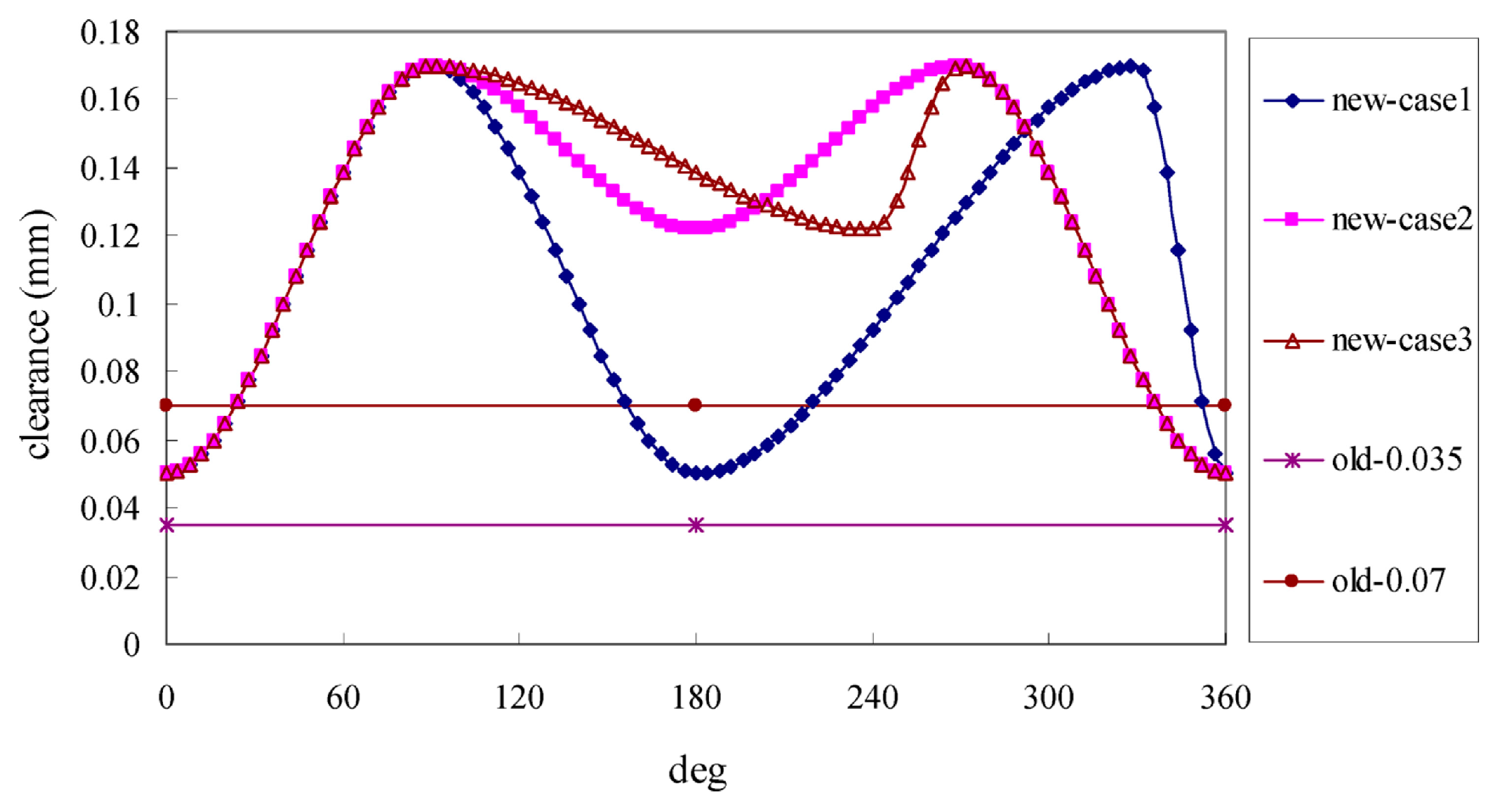
Figure 13.
The trochoidal gear sets made of (a) polyoxymethylene (POM), (b) polyphenylsulfone (PPS) and (c) polyether ether ketone (PEEK), the dimensional nomenclature, the intertooth radial clearance hr and axial clearance ha (Stryczek et al. [80]).
Figure 13.
The trochoidal gear sets made of (a) polyoxymethylene (POM), (b) polyphenylsulfone (PPS) and (c) polyether ether ketone (PEEK), the dimensional nomenclature, the intertooth radial clearance hr and axial clearance ha (Stryczek et al. [80]).

Figure 14.
Pareto industry pump designs used in automotive applications (Robinson and Vacca [86]).
Figure 14.
Pareto industry pump designs used in automotive applications (Robinson and Vacca [86]).

Figure 15.
The main menu of the ‘Gerotor Pump Tool’ (Klopsch et al. [95]).
Figure 15.
The main menu of the ‘Gerotor Pump Tool’ (Klopsch et al. [95]).

Figure 16.
Particle image velocimetry (PIV) contours and comparison of velocity vector field between PIV and computational fluid dynamics (CFD) (Garcia-Vilchez et al. [100]).
Figure 16.
Particle image velocimetry (PIV) contours and comparison of velocity vector field between PIV and computational fluid dynamics (CFD) (Garcia-Vilchez et al. [100]).

Figure 17.
Variable timing gerotor pump (Rundo and Nervegna [1]).
Figure 17.
Variable timing gerotor pump (Rundo and Nervegna [1]).

Figure 18.
Minimum clearance height variation during one rotation (360º) and during one phase (60º) for a gerotor pump unit with fixed axes (Ivanović et al. [110]).
Figure 18.
Minimum clearance height variation during one rotation (360º) and during one phase (60º) for a gerotor pump unit with fixed axes (Ivanović et al. [110]).

Figure 19.
Gear position study. (a) Comparison between tip clearance variation over an entire revolution for nominal and variable interaxis position; (b) Difference between the actual and the nominal positions of the outer rotor. (Pellegri and Vacca [121]).
Figure 19.
Gear position study. (a) Comparison between tip clearance variation over an entire revolution for nominal and variable interaxis position; (b) Difference between the actual and the nominal positions of the outer rotor. (Pellegri and Vacca [121]).

Figure 20.
Flow chart and optimizing loop in the computer-aided design (CAD) method (Gherardini et al. [131]).
Figure 20.
Flow chart and optimizing loop in the computer-aided design (CAD) method (Gherardini et al. [131]).

Figure 21.
The hydraulic orbital motor (a) Gerotor assembly in a hydraulic orbital motor; (b) Geroler.
Figure 21.
The hydraulic orbital motor (a) Gerotor assembly in a hydraulic orbital motor; (b) Geroler.
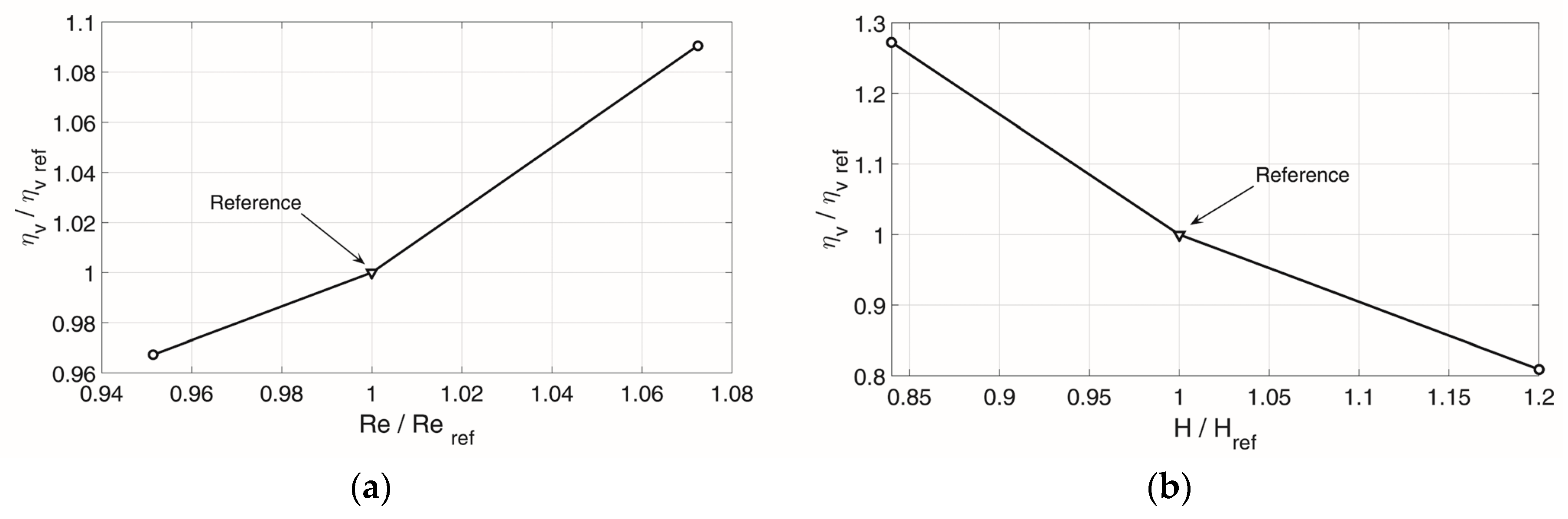
Figure 22.
The hydraulic orbital motor (a) Gerotor assembly in a hydraulic orbital motor; (b) Geroler.
Figure 22.
The hydraulic orbital motor (a) Gerotor assembly in a hydraulic orbital motor; (b) Geroler.

Figure 23.
Measured tooth-top profiles for a single tooth from each of the internal gears, following 500 h of steady-state testing, are shown superimposed over the ideal, tooth-top profile. Uncoated samples C, D and E and coated samples 6, 7 and 8 (Bates et al. [152]).
Figure 23.
Measured tooth-top profiles for a single tooth from each of the internal gears, following 500 h of steady-state testing, are shown superimposed over the ideal, tooth-top profile. Uncoated samples C, D and E and coated samples 6, 7 and 8 (Bates et al. [152]).

Figure 24.
The hydraulic gerotor motor with a floating outer ring. (a) Hydraulic gerotor motor design (174 mm × 250 mm); (b) Rotors and lobes. (Strmčnik and Majdič [154]).
Figure 24.
The hydraulic gerotor motor with a floating outer ring. (a) Hydraulic gerotor motor design (174 mm × 250 mm); (b) Rotors and lobes. (Strmčnik and Majdič [154]).

Figure 25.
Photography of the manufactured macro prototype (a) and exploded view (b) (Leester-Schädel et al. [161]).
Figure 25.
Photography of the manufactured macro prototype (a) and exploded view (b) (Leester-Schädel et al. [161]).

Figure 26.
The conventional outer rotor replaced by rollers (Heisel and Mishev [164]).
Figure 26.
The conventional outer rotor replaced by rollers (Heisel and Mishev [164]).

Figure 27.
GeroMAG trochoidal-envelope toothed gear set: Non-shaft-driven magnetically-driving outer rotor.
Figure 27.
GeroMAG trochoidal-envelope toothed gear set: Non-shaft-driven magnetically-driving outer rotor.
Table 1.
Number of times the first thirty keywords have been used in the literature.
| Keywords (1 to 10) | Times | Keywords (11 to 20) | Times | Keywords (21 to 30) | Times |
|---|---|---|---|---|---|
| pump | 83 | power | 13 | teeth | 10 |
| gerotor | 60 | pressure | 13 | profile | 9 |
| gear | 37 | cycloidal | 12 | analysis | 9 |
| flow | 28 | clearance | 12 | internal | 8 |
| trochoidal | 19 | port | 11 | wear | 7 |
| hydraulic | 17 | oil | 10 | system | 7 |
| design | 17 | motor | 10 | rotary | 6 |
| CFD | 17 | simulation | 10 | lubrication | 6 |
| contact | 15 | efficiency | 10 | leakage | 6 |
| stress | 14 | method | 10 | modelling | 6 |
Table 2.
Manufacturing tolerances for a gerotor pump (Data from Jamadar et al. [65]).
Table 2.
Manufacturing tolerances for a gerotor pump (Data from Jamadar et al. [65]).
| Manufacturing | Part | Tolerance |
|---|---|---|
| Radial clearance | Inner to outer profile | 25–80 × 10−6 m |
| External gear to housing | 25–80 × 10−6 m | |
| Side clearance | Internal gear | 2–4 × 10⁻⁶ m |
| External gear | 2–4 × 10⁻⁶ m | |
| Flatness | Housing | 25 × 10−6 m |
| Cover | 25 × 10−6 m | |
| Internal gear | 1 × 10⁻⁶ m | |
| External gear | 1 × 10⁻⁶ m | |
| Surface finishing | Housing | 60 × 10−6 m |
| Cover | 15–20 × 10−6 m | |
| Internal gear | 15–20 × 10−6 m | |
| External gear | 15–20 × 10−6 m |
© 2019 by the authors. Licensee MDPI, Basel, Switzerland. This article is an open access article distributed under the terms and conditions of the Creative Commons Attribution (CC BY) license (http://creativecommons.org/licenses/by/4.0/).
Share and Cite
MDPI and ACS Style
Gamez-Montero, P.J.; Codina, E.; Castilla, R. A Review of Gerotor Technology in Hydraulic Machines. Energies 2019, 12, 2423. https://doi.org/10.3390/en12122423
AMA Style
Gamez-Montero PJ, Codina E, Castilla R. A Review of Gerotor Technology in Hydraulic Machines. Energies. 2019; 12(12):2423. https://doi.org/10.3390/en12122423
Chicago/Turabian StyleGamez-Montero, Pedro Javier, Esteve Codina, and Robert Castilla. 2019. "A Review of Gerotor Technology in Hydraulic Machines" Energies 12, no. 12: 2423. https://doi.org/10.3390/en12122423
Note that from the first issue of 2016, this journal uses article numbers instead of page numbers. See further details here.