Internal Flow in an Enhanced Tube Having Square-cut Twisted Tape Insert


1
Department of Mechanical Engineering, Graduate School of Engineering, Universitas Sebelas Maret, Kampus UNS Kentingan, Jl. Ir. Sutami 36A Kentingan, Surakarta 57126, Indonesia
2
Research Group of Sustainable Thermofluids, Faculty of Engineering, Universitas Sebelas Maret, Kampus UNS Kentingan, Jl. Ir. Sutami 36A Kentingan, Surakarta 57126, Indonesia
3
Department of Informatics, Universitas Atma Jaya Yogyakarta, Jl. Babarsari 44 Yogyakarta 55281, Indonesia
4
Department of Mechanical Engineering, Mataram University, Jl. Majapahit 62, Mataram 83125, Indonesia
5
Institute of Innovative Research, Tokyo Institute of Technology, 2-12-1 Ookayama, Meguro-ku, Tokyo 152-8550, Japan
*
Authors to whom correspondence should be addressed.
Energies 2019, 12(2), 306; https://doi.org/10.3390/en12020306
Submission received: 25 December 2018
/
Revised: 14 January 2019
/
Accepted: 16 January 2019
/
Published: 19 January 2019
(This article belongs to the Special Issue Heat Transfer Enhancement)
Abstract
:In this study, a numerical simulation has been conducted in order to evaluate the thermal hydraulic performance of a turbulent single-phase flow inside an enhanced tube equipped with a square-cut twisted tape (STT) insert. The classical twisted tape (CTT) insert was also investigated for comparison. The k-ε renormalized group turbulence model has been utilized as the turbulent model. Various twist ratios (y/W) of 2.7, 4.5, and 6.5 were investigated for the Reynolds number range of 8000–18,000, with water as the working fluid. The numerical results indicated that, in comparison with the plain tube (PT), the tube equipped with the STT with the twist ratios of 2.7, 4.5, and 6.5 led to an increase in the values of the Nusselt number and friction factor in the inner tube by 45.4–80.7% and 2.0–3.3 times, respectively; in addition, the highest thermal performance of 1.23 has been obtained. The results further indicated that the tube equipped with the CTT of the same twist ratios improved the Nusselt number and friction factor in the inner tube by 40.3–74.4% and 1.7–3.0 times, respectively, in comparison with the PT; further, the maximum thermal performance of 1.18 was achieved.
1. Introduction
Numerous research studies have been performed on heat exchangers, to enhance the heat transfer, in order to achieve a higher heat exchange performance [1,2]. For this purpose, the following efforts have been reported in our previous works: a direct contact system for adsorption cycle [3,4,5], using nanofluid as the working fluid [6,7]; improvement of maldistribution inside the distributor of heat exchangers [8,9,10]; using inserts inside the tubes [11,12,13,14,15]. Based on the published reports, it is known that the investigations on passive heat transfer enhancement methods using various inserts do not consider the existing problems. The designs used in the above-said investigations utilize an enhanced tube equipped with various inserts to achieve a high heat transfer rate. However, those designs were not able to reduce the power required for pumping fluids. Therefore, several efforts have been made to lower the pump duty, to achieve the required performance under several design constraints. Passive heat transfer enhancement methods, which are currently adopted by many researchers, mainly employ swirl devices with twisted tapes [16,17,18,19]. Twisted tape inserts are one of the popular techniques available, to enhance the heat transfer performance of heat exchangers, due to their high economic performance and easy installation. They create a continuously swirling stream to enhance the heat transfer rate. The swirling flow induces turbulence near the pipe walls, which results in a longer fluid flow path in the pipeline, improved fluid mixing, and reduced thermal boundary area, thereby increasing the rate of convection heat transfer. We investigated experimentally the perforated twisted tapes at a constant twist ratio (y/W) of 3.97 with various axial pitch ratios at the Reynolds number range of 5400–17,500 [17]. The result indicated that the thermal performance increased with the decrease in axial pitch ratio. We continued to examine experimentally the V-cut twisted tapes for turbulent flow at the similar operating conditions and a constant twist ratio (y/W) of 3.97 with various width ratios [18]. It demonstrated that as the width ratio decreased, the thermal performance increased.
Results indicate that a significant improvement in the heat transfer cannot be realized together with the improvement in the friction factor (pressure drop). Several modified and improved twisted tapes have been designed to minimize the pressure loss [20,21,22,23,24,25]; they have been observed under several conditions to determine the key factors affecting the heat transfer and pressure drop of the heat exchangers. An experimental study on the effect of peripherally-cut twisted tape inserts on the thermal performance characteristics in a tube was evaluated in [26]. It was found that the peripherally-cut insert can potentially improve the system performance. Moreover, the system performance can also be improved by increasing the depth ratio and decreasing the width ratio. A square-cut twisted tape insert in the heat exchanger has been adopted in [27]. It was demonstrated that the square-cut twisted tape inserts can provide higher performance than the plain twisted tape inserts. Furthermore, Murugesan et al. [28] studied a V-cut twisted tape insert and performed an experimental study on the heat and friction factor characteristics. They found that the thermal performance was affected by the twist and width ratios. Bhuiya et al. [29] studied the thermal performance in an enhanced tube using perforated twisted tape inserts. It was found that the perforated twisted tape inserts could provide a significantly higher performance compared to that of the plain tubes. In addition, small cut variations using rectangular-cut twisted tape inserts were observed in [30].
Knowledge of the fluid flow mechanisms and heat transfer characteristics based on numerical approach is required, because it can be an important tool for further improvement of the heat exchanger performance. The influence of the insertion of twisted tape inserts in the tube and the enhancement of heat transfer have been clearly studied in [31] using simulation. It was found that, in the case of laminar flows, the tubes with twisted tape inserts achieved a two-times higher heat transfer rate than the tubes without twisted tape inserts. Furthermore, the heat transfer coefficients inside the corrugated tube having a twisted tape insert has been numerically evaluated in [32]. It was found that the numerical results showed a good agreement with the experimental results, which the difference between them was smaller than ±20%.
However, the above-mentioned studies did not encompass all the available enhancement methods. It is supposed that various other methods, especially numerical methods, need to be studied for heat transfer enhancement. Based on experiments, numerical methods are advantageous for predicting the system performance. Unfortunately, most of the experimental works related to the heat transfer augmentation which are adopting twisted tape inserts do not explain the fluid flow and heat transfer mechanisms. Therefore, after publishing Refs. [17,18], we were further motivated to extend the research to evaluate the thermal hydraulic performance of a turbulent single-phase flow inside an enhanced tube equipped with an innovative square-cut twisted tape (STT) insert. Thus, the current study retains its research originality compared with the previous works. In addition, in this study, we validate the obtained results through comparison with the previous results based on experiments [18]. Comparison with numerical results of the classical twisted tape (CTT) insert and the plain tube (PT) was provided for evaluation.
2. Numerical Method
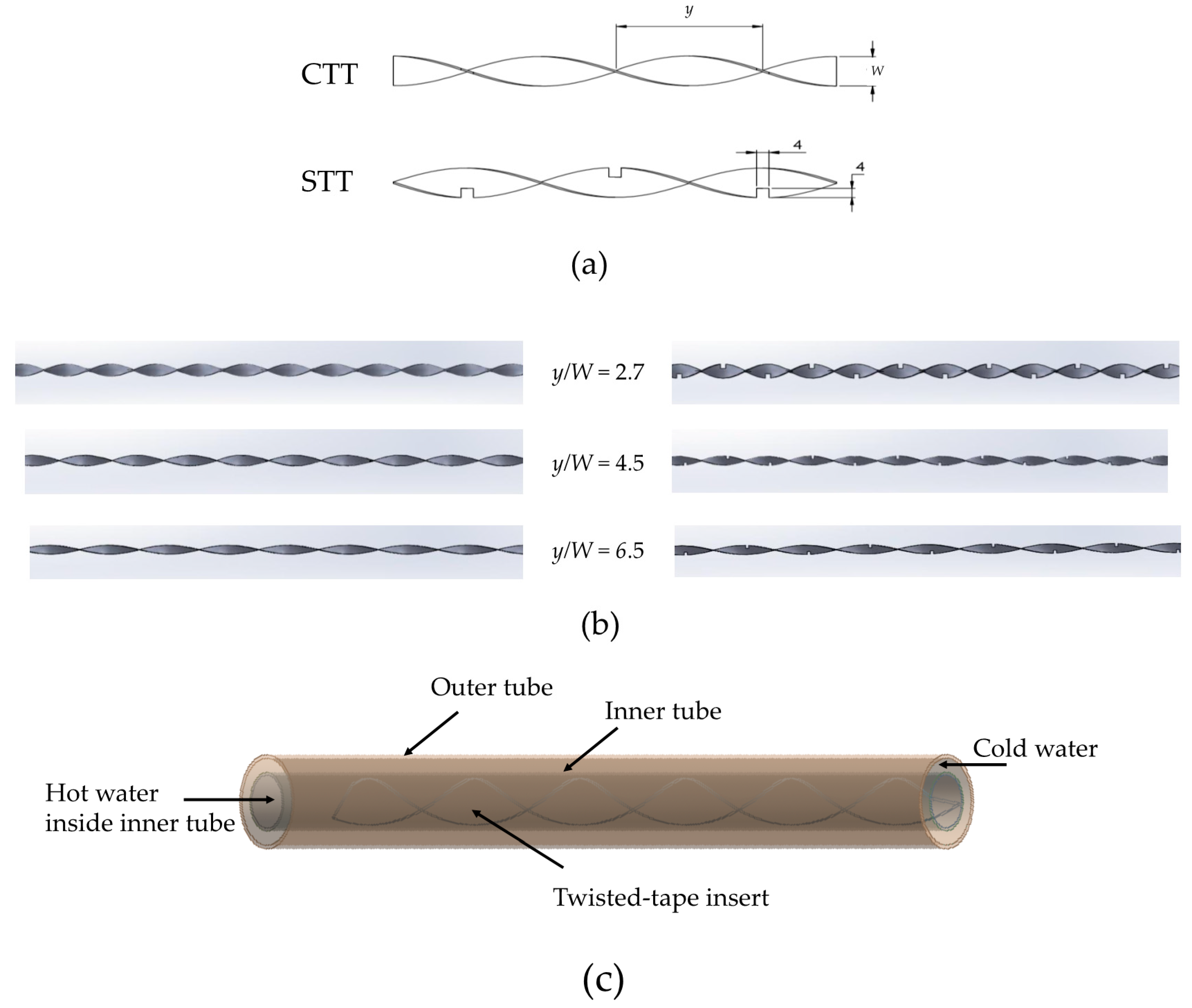
Figure 1 shows the geometry of the concentric tube comprising an inner tube for hot fluid flow and an outer tube for cold fluid flow, based on Refs. [17,18]. A computational domain was developed, as shown in Figure 1, and the boundary condition to be applied in the domain was decided. The inner tube had an inside diameter (di) of 14.3 mm and an outside diameter (do) of 15.8 mm; the outer tube had an inside diameter (Di) of 23.4 mm and an outside diameter (Do) of 25.4 mm; the pipe length (L) was 2110 mm. All the tapes had a width (W) of 12.6 mm and a thickness (δ) of 0.7 mm. The twist ratio is defined as the ratio between the twist pitch (y) and tape width (W). The inlet temperature of the hot fluid was 333.15 K, with the Reynolds number (Re) of 8000–18,000 for the velocity inlet, whereas the inlet temperature for the cold fluid was 300.15 K, with a constant mass flow rate of 0.1027 kg/s. The exit of the tube was connected to the pressure outlet.
To evaluate the thermal performance of the fluid flow and heat transfer, and the characteristics of the thermal performance, in this study, water is utilized as the working fluid. The hot water and cold water are transported through the inner and outer tubes, respectively. The thermo-physical properties of water [15], which are considered as the inlet values during the calculation, are listed in Table 1.
Based on the thermo-physical properties of the working fluid (density, velocity, and viscosity) and the inner diameter of the inner tube, Re can be estimated as:
where ρ, u, and μ are density, velocity, and dynamic viscosity of the water, respectively. In addition, to facilitate velocity variations, Re is set to be between 8000 and 18,000.
Moreover, the heat transfer characteristic, which is defined as the Nusselt number (Nu), is calculated as:
where h and k are convective heat transfer coefficient and thermal conductivity of the working fluid, respectively. Dh devotes the hydraulic diameter of inner tube.
The fluid flow characteristics are evaluated by employing the friction factor (f), which can be estimated as:
As shown in Equation (3), f is influenced strongly by the pressure difference (ΔP) between the tube inlet and outlet.
Several assumptions are adopted in the current work to solve the numerical simulation [15]: (1) The flow caused in the pipe by the inserts is turbulent and incompressible, (2) the flow is in a steady state, (3) natural convection and thermal radiation are negligible, and (4) the properties of the fluid used depend on the temperature. The three governing equations, covering continuity, momentum, and energy are adopted in order to perform the calculation. These can be defined as follows:
Continuity equation:
Momentum equation:
Energy equation:
where ρ, u, p, μ, cp, and T are fluid density, mean velocity, pressure, fluid dynamic viscosity, specific heat, fluid thermal conductivity, and temperature, respectively. In addition, the subscripts i and k represent the direction in both i and k, respectively.
The modeling and calculation is assumed to be three-dimensional, turbulent, and steady. In addition, the tube wall is assumed to be adiabatic, and a no-slip condition is considered at the tube walls. Similar to the tube walls, the boundary condition between the fluid and the inserts is also assumed to be adiabatic. In this study, the commercial software Fluent 15 is used for modelling and calculation [33]. This software basically runs based on the finite volume method. This method is also applied to solve Equations (4)–(6), together with the k–ε renormalized group turbulence model. In addition, the standard-pressure and second-order upwind discretization methods are adopted in order to calculate both momentum and energy. The SIMPLE algorithm is employed to calculate the pressure–velocity coupling. Moreover, the tetrahedron-cell mesh configuration is adopted to validate the plain tube and all twisted tape inserts. The face sizing method is employed in the model in several areas.
3. Results and Discussion
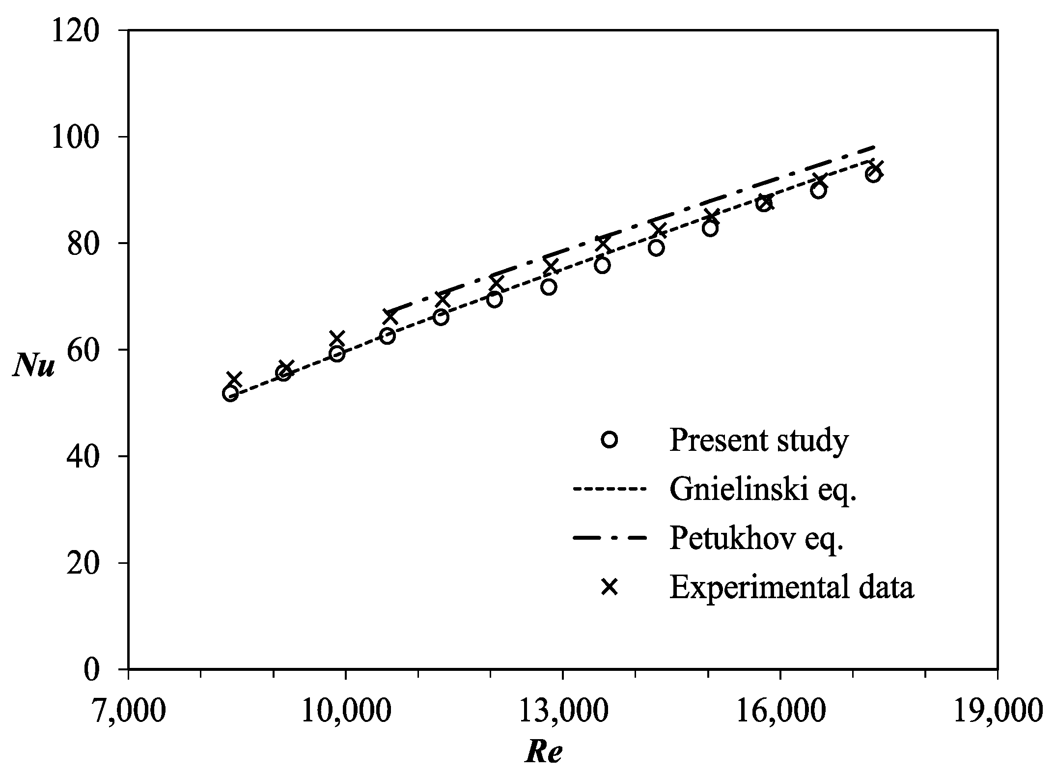
During the calculation, the grid is modelled and designed based on the tetrahedral grid type. To make more confident that the grid is sufficiently dense as well as fulfills the grid independence, face sizing is also performed. The modelled grid contains approximately 1,380,314 cells, which are used to simulate the case of a smooth-tube. Furthermore, the thermal hydraulic characteristics of the plain tube calculated in this study are compared with the several correlations which have been established in order to measure the results accuracy of the calculation. Nu is compared and evaluated using the Petukhov and Gnielinski equations [34], whereas f is evaluated using the Petukhov and Blasius equations [35].
The Petukhov equation is estimated as:
for 104 < Re < 5 × 10⁶.
In addition, the Gnielinski equation is given by:
for 1 × 10³ < Re < 5 × 10⁶.
The Petukhov correlation for friction factor is:
for 104 < Re < 106.
f = (0.790 ln Re − 1.64)−2
The Blasius correlation used to predict the friction factor is given by:
for 4 × 10³ < Re < 105.
f = 0.3164 Re−0.25
Figure 2 and Figure 3 respectively represent the comparison of the Nu and f for the smooth tube with the well-known correlations. Under all the evaluated cases, the difference between the results of the current study with the established correlations is relatively small. Therefore, it can be concluded that the results of calculation in the current study show a good accuracy.
The deviations of the numerical results for the heat transfer (Nu), in comparison with the established correlations, are within ±5.98% for the Petukhov correlation and ±2.00% for the Gnielinski correlation; in the case of f, the deviations are within ±6.98% for the Blasius correlation and ±5.67% for the Petukhov correlation. Moreover, the differences in Nu and friction factor, in comparison with the experiments [18], are less than 5% and 7%, respectively.
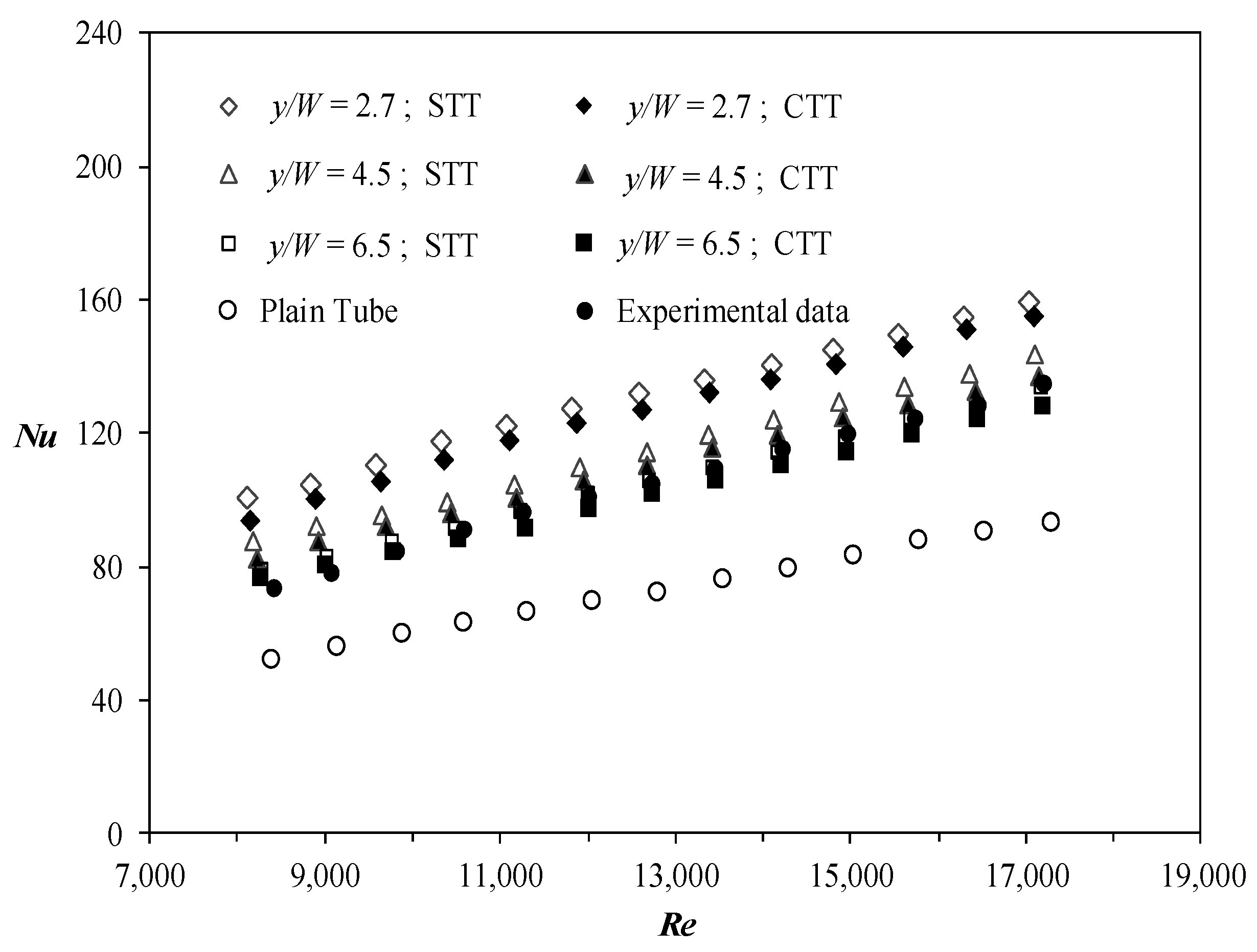
The tetrahedral grid is adopted for meshing during the calculation. To improve the calculation accuracy, the grid is highly converged in the insertion area. Approximately 2,600,000 cells are generated and employed for the tube with the twisted tape inserts. The effect of the twisted tape inserts on the heat transfer characteristics is represented in Figure 4. In general, a higher Nu can be obtained by using the twisted tape inserts than the smooth tube. Nu is greatly influenced by the distribution of fluid temperature which is flowing inside the enhanced tube. It can be expected that, by fixing the inlet conditions (cold and hot fluids) for all the evaluated cases, the turbulent flow generation will be apparent.
A comparison between the plain tube (PT, without insertion) and the corresponding classical twisted tape (CTT) inserts is also conducted to evaluate the heat transfer enhancement by the STTs, as shown in Figure 4. It can be observed that the heat transfer, in terms of Nu, is improved with the increase in Re (for most cases). The turbulent intensity of the flow increases following the increase in Re, leading to the enhancement of the convective heat transfer. These results are consistent with the those of the previous studies [3,4,5,6,7,9,10]. Figure 4 further shows that, for the STT, the pitch ratio y/W of 2.7 yields the highest Nu followed by those of 4.5 and 6.5. This indicates that, for the same pitch ratio, employing the STTs provides better results than the CTTs. Using the STTs can improve the turbulent intensity of the fluid near the tube walls. Furthermore, the vorticity behind the square-cut increases, resulting in a higher convective heat transfer rate, compared with that of the CTTs. The Nu values for STTs and CTTs for the corresponding pitch ratios of 2.7, 4.5, and 6.5 range between 74–81%, 53–59%, and 40–45% higher than the plain tube, respectively.
Figure 5 shows the comparisons of the temperature distribution of both smooth and enhanced tubes with STTs, CTTs, and plain tubes at a Re of 14,100 at various cross sections (x/D). In a tube having twisted tape inserts, in all geometries, the temperature is more equally distributed. Furthermore, as the twist pitch increases, the temperature distribution also shows a tendency towards homogeneous temperature distribution.
The temperature contours of both the CTTs and STTs display the same tendency for the corresponding twist ratios. Figure 6 shows the streamline in cross section under Re of 14,100. It is clear that, for the tubes with STTs and CTTs, an improved temperature distribution can be achieved, leading to more excellent temperature gradient compared to the smooth tube. The better temperature distribution leads to a higher temperature difference between the tube inlet and outlet, thereby improving the convective heat transfer coefficient. In addition, in the case of y/W = 2.7 CTT, the highest temperature gradient and superior temperature distribution can be obtained over the other tube designs, thereby yielding the best performance for this geometry.
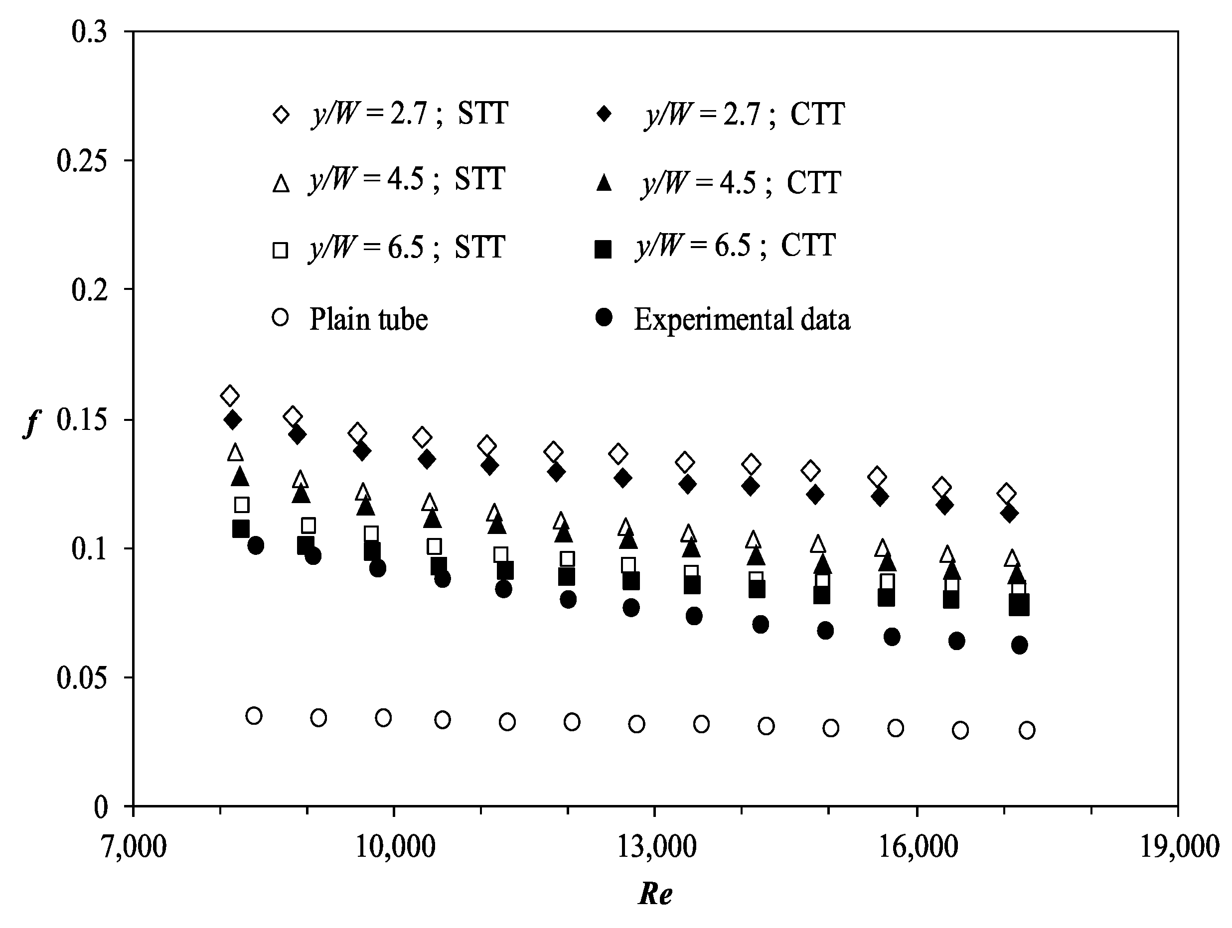
Figure 7 depicts the variation of friction factor (f) with Re for plain tube and three different twist pitch ratios of the CTTs and STTs. The f value displays a decreasing trend with the increase in Re. Further, STTs provide a higher f compared with the CTTs, for the corresponding pitch ratio. The f values for the STTs and CTTs for the corresponding pitch ratios of 2.7, 4.5, and 6.5 range between 3.0–3.3, 2.3–2.5, and 1.7–2.0 times higher than the plain tube, respectively. Compared with the case of CTTs, the flow disturbance in the case of STTs increases the tangential velocity between the secondary flow and the tube wall surface. As expected, the twisted tape tubes with both the CTT and STT exhibit a sharper decline in f compared with the plain tube, which is attributed to blockage and the subsequent decline in the flow’s momentum by the twisted tape tube, as well as the pressure drop for the corresponding twisted tape tube.
Figure 8 shows the comparison of velocity distributions of both smooth and enhanced tubes with the STTs, CTTs, and plain tube at a Re of 14,100 at various cross sections (x/D). The plain tube domain reaches its maximum velocity at the center, thereby indicating a fully developed flow in these locations. It is seen that the velocity is almost similar at all locations. It is clear that in the plain tube, the velocity near the walls is low, owing to the absence of the twisted tape. With the addition of the twisted tape inserts (both CTTs and STTs), a uniform distribution of the velocity is achieved due to the swirls generated by the twisted tape inserts. Compared with the plain tube, the tube fitted with the STT achieves higher velocity, owing to the increased velocity of the flow near the walls due to the swirls generated by the tape. The behavior of the STTs and CTTs is similar for the corresponding pitch ratios (Figure 4 and Figure 5). It is expected that the insertion of the STT with square-cuts will create a new flow pattern. The working fluid flows through the square-cuts, and a new flow pattern is formed as an axial flow. The new flow pattern causes an increasingly random flow of the working fluid, thereby increasing the vorticity formation (due to the working fluid flowing through the square-cuts), which results in an increase in the heat transfer rate as shown in the Figure 4.
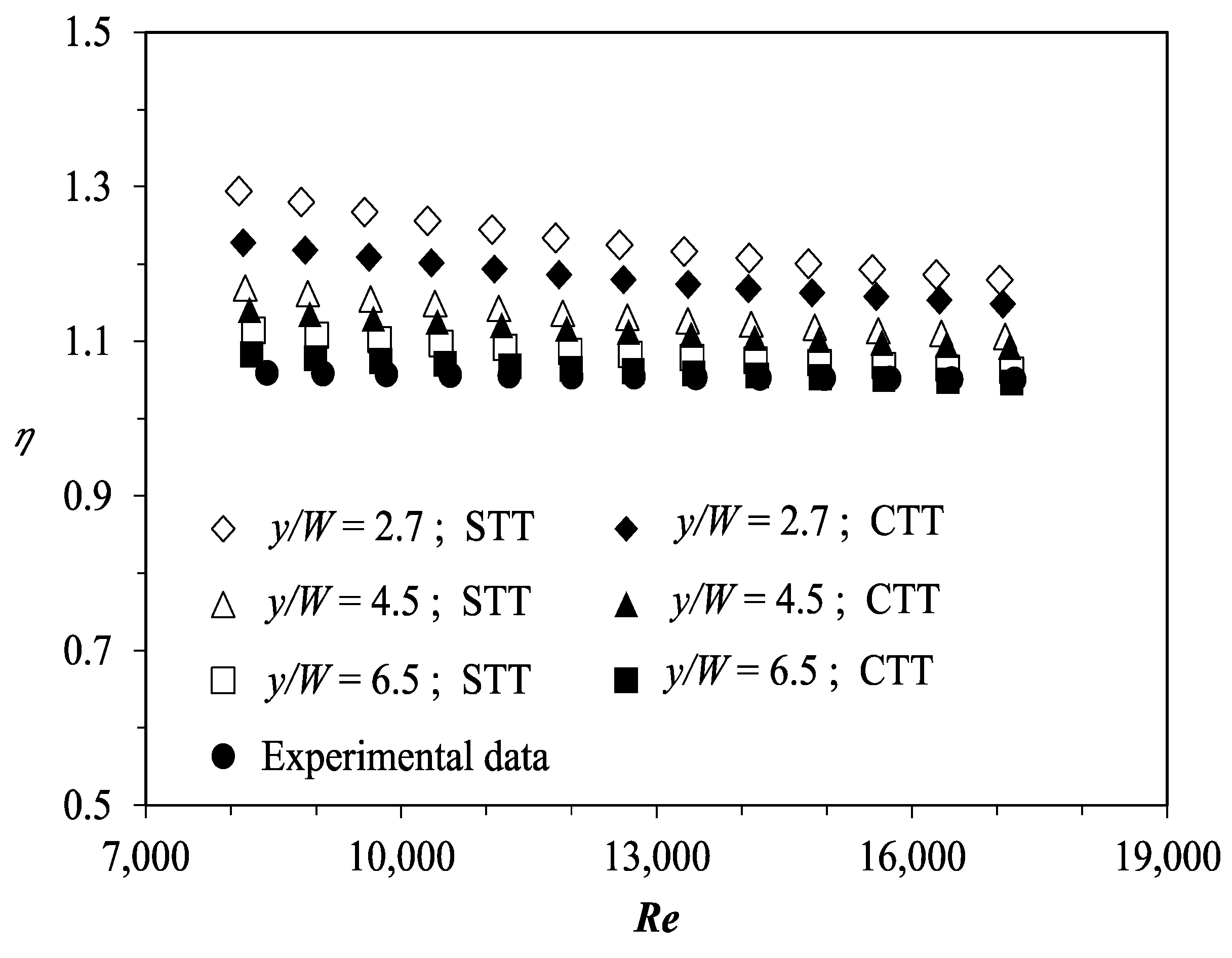
The thermal performance (η) with Re for a plain tube and three different twist pitch ratios of the CTTs and STTs is presented in Figure 9. The thermal performance of the enhanced tube heat exchanger can be determined as the ratio of both heat transfer and friction factor characteristics of the enhanced tube to those of the basic device, which only has the basic dimensions without design enhancements [36]. η can be estimated as follows:
As shown in Figure 9, all the results of the plain tube, CTTs, and STTs demonstrate a similar tendency. η decreases with the increase in Re. Both the CTT and STT are more effective in disrupting the flow at lower Re. η values for the STTs and CTTs for the corresponding pitch ratios of 2.7, 4.5, and 6.5 range between 1.18–1.23, 1.11–1.13, and 1.06–1.09 times higher than those of the plain tube, respectively. The results of the thermal performance indicate that, the efforts to improve the heat transfer performance have yielded significant results, but with an increase in f. Therefore, the geometrical modification of the inserts for an enhanced tube is advantageous in offering practical solutions for improving the thermal performance of heat exchangers. It is evident that the velocity distribution significantly depends on the local momentum of the working fluid due to the geometry of the enhanced tube, thereby affecting the thermal hydraulic characteristics (Figure 5 and Figure 8). These findings can contribute to the study of heat transfer enhancement, in order to minimize the energy consumption in a compact heat exchanger.
In addition, as shown in Figure 4, Figure 7 and Figure 9, the experimental results from our previous work in Ref. [18] are provided for the correlations of Nu, friction factor, and the pressure drop, for the corresponding Re, respectively. The experimental results are shown by solid circles, which have a geometry installed with CTT. From Figure 4, it is clear that the experimental results are in good agreement with the present results. Further, Figure 7 and Figure 9 display a similar tendency for friction factor and thermal performance, respectively. There are small discrepancies between the experimental and numerical results due the differences in the twist ratio (y/W) of the CTT. The twist ratio of 3.97 was used in the experiment, in this study [18]. Therefore, the numerical method used in this study can be considered potential to be used to study the thermal hydraulic performance of a turbulent single-phase flow inside an enhanced tube equipped with an STT insert.
4. Concluding Remarks
A numerical study of an enhanced tube employing the CTTs and STTs with various pitch ratios was performed. The important conclusions of this study are as follows:
- Nu, f, and η of both the CTTs and STTs with various pitch ratios of the enhanced tube are higher compared to those of the plain tube. the decrease of the pitch ratio leads to the increase of Nu, f, and η.
- STT with y/W = 2.7 yields higher heat transfer rate, friction factor, and thermal performance factor.
- The highest increases in Nu and f of the enhanced tube can reach 81% and 3.3 times greater than ones of the smooth tube, respectively.
- The thermal performance factor has been visualized and it can reach a value of 1.23.
- Based on both the temperature and velocity distributions at the cross sections, the heat transfer mechanism has been definitely evaluated.
Author Contributions
A.T.W. conceived the main concept. The second, third, and fourth authors contributed to the investigation and data analysis. The first and fifth authors contributed significantly to the supervision of the research. The first author prepared the manuscript. Finally, all the authors contributed in writing and checking the final manuscript.
Funding
This research is partly funded by Universitas Sebelas Maret (Research Register No.: 0031087104832018).
Acknowledgments
The authors are grateful to their former colleague, Aldi Ruvian, for kind support and assistance in data collection and analysis. In addition, A.T. Wijayanta acknowledges the Ministry of Research, Technology and Higher Education of the Republic of Indonesia, for the research visit support to Tokyo Institute of Technology, Japan, via the World Class Professor Program Scheme B (Fiscal Year 2018), in order to finalize the analysis and manuscript.
Conflicts of Interest
The authors declare that no conflict of interest exists.
References
- Honda, H.; Wijayanta, A.T.; Takata, N. Condensation of R407C in a horizontal microfin tube. Int. J. Refrig. 2005, 28, 203–211. [Google Scholar] [CrossRef]
- Xue, Y.; Ge, Z.; Du, X.; Yang, L. On the heat transfer enhancement of plate fin heat exchanger. Energies 2018, 11, 1398. [Google Scholar] [CrossRef]
- Xue, B.; Tahara, K.; Nakashima, K.; Noda, A.; Oktariani, E.; Wijayanta, A.T.; Nakaso, K.; Fukai, J. Numerical simulation for steam generation process in a novel zeolite-water adsorption heat pump. J. Chem. Eng. Jpn. 2012, 45, 408–416. [Google Scholar] [CrossRef]
- Fukai, J.; Wijayanta, A.T. Potential ability of zeolite to generate high-temperature vapor using waste heat. AIP Conf. Proc. 2018, 1931, 020001. [Google Scholar] [CrossRef]
- Yaningsih, I.; Wijayanta, A.T.; Miyazaki, T.; Koyama, S. Analysis of heat and mass transfer characteristics of desiccant dehumidifier system with honeycomb configuration. Appl. Therm. Eng. 2018, 144, 658–669. [Google Scholar] [CrossRef]
- Kristiawan, B.; Santoso, B.; Juwana, W.E.; Ramadhan, R.M.; Riandana, I. Numerical investigation of laminar convective heat transfer for TiO2/water nanofluids using two-phase mixture model (Eulerian approach). AIP Conf. Proc. 2017, 1788, 030002. [Google Scholar] [CrossRef]
- Kristiawan, B.; Santoso, B.; Wijayanta, A.T.; Aziz, M.; Miyazaki, T. Heat transfer enhancement of TiO2/water nanofluid at laminar and turbulent flows: A numerical approach for evaluating the effect of nanoparticle loadings. Energies 2018, 11, 1584. [Google Scholar] [CrossRef]
- Wijayanta, A.T.; Miyazaki, T.; Koyama, S. Liquid-vapor phase distribution in horizontal headers with upward minichannel-branching conduits. Exp. Therm. Fluid Sci. 2016, 76, 264–274. [Google Scholar] [CrossRef]
- Wijayanta, A.T.; Miyazaki, T.; Koyama, S. Refrigerant distribution in horizontal headers with downward minichannel-branching conduits: Experiment, empirical correlation and two-phase flow pattern map. Exp. Therm. Fluid Sci. 2017, 81, 430–444. [Google Scholar] [CrossRef]
- Wijayanta, A.T.; Miyazaki, T.; Koyama, S. Note on refrigerant R134a flow maldistribution in a header type evaporator. Int. J. Refrig. 2018, 95, 1–9. [Google Scholar] [CrossRef]
- Wijayanta, A.T.; Istanto, T.; Kariya, K.; Miyara, A. Heat transfer enhancement of internal flow by inserting punched delta winglet vortex generators with various attack angles. Exp. Therm. Fluid Sci. 2017, 87, 141–148. [Google Scholar] [CrossRef]
- Yaningsih, I.; Wijayanta, A.T.; Miyazaki, T.; Koyama, S. Impact of blockage ratio on thermal performance of delta-winglet vortex generators. Appl. Sci. 2018, 8, 181. [Google Scholar]
- Yaningsih, I.; Wijayanta, A.T.; Miyazaki, T.; Koyama, S. Thermal hydraulic characteristics of turbulent single-phase flow in an enhanced tube using louvered strip insert with various slant angles. Int. J. Therm. Sci. 2018, 134, 355–362. [Google Scholar] [CrossRef]
- Wijayanta, A.T.; Yaningsih, I.; Aziz, M.; Miyazaki, T.; Koyama, S. Double-sided delta-wing tape inserts to enhance convective heat transfer and fluid flow characteristics of a double-pipe heat exchanger. Appl. Therm. Eng. 2018, 145, 27–37. [Google Scholar] [CrossRef]
- Wijayanta, A.T.; Aziz, M.T.; Kariya, K.; Miyara, A. Numerical study of heat transfer enhancement of internal flow using double-sided delta-winglet tape insert. Energies 2018, 11, 3170. [Google Scholar] [CrossRef]
- Ray, S.; Date, A.W. Friction and heat transfer characteristics of flow through square duct with twisted tape insert. Int. J. Heat Mass Transf. 2003, 46, 889–902. [Google Scholar] [CrossRef]
- Yaningsih, I.; Istanto, T.; Wijayanta, A.T. Experimental study of heat transfer enhancement in a concentric double pipe heat exchanger with different axial pitch ratio of perforated twisted tape inserts. AIP Conf. Proc. 2016, 1717, 030012. [Google Scholar] [CrossRef]
- Yaningsih, I.; Wijayanta, A.T.; Miyazaki, T.; Koyama, S. V-cut twisted tape insert effect on heat transfer enhancement of single phase turbulent flow heat exchanger. AIP Conf. Proc. 2018, 1931, 030038. [Google Scholar] [CrossRef] [Green Version]
- Bellos, E.; Tzivanidis, C. Enhancing the performance of evacuated and non-evacuated parabolic trough collectors using twisted tape inserts, perforated plate inserts and internally finned absorber. Energies 2018, 11, 1129. [Google Scholar] [CrossRef]
- Patil, A.G. Laminar flow heat transfer and pressure drop characteristics of power-law fluids inside tubes with varying width twisted tape inserts. J. Heat Transf. 2000, 122, 143–149. [Google Scholar] [CrossRef]
- Saha, S.K.; Dutta, A.; Dhal, S.K. Friction and heat transfer characteristics of laminar swirl flow through a circular tube fitted with regularly spaced twisted-tape elements. Int. J. Heat Mass Transf. 2001, 44, 4211–4223. [Google Scholar] [CrossRef]
- Eiamsa-ard, S.; Wongcharee, K.; Sripattanapipat, S. 3-D Numerical simulation of swirling flow and convective heat transfer in a circular tube induced by means of loose-fit twisted tapes. Int. Commun. Heat Mass Transf. 2009, 36, 947–955. [Google Scholar] [CrossRef]
- Eiamsa-ard, S.; Thianpong, C.; Eiamsa-ard, P.; Promvonge, P. Convective heat transfer in a circular tube with short-length twisted tape insert. Int. Commun. Heat Mass Transf. 2009, 36, 365–371. [Google Scholar] [CrossRef]
- Jaisankar, S.; Radhakrishnan, T.K.; Sheeba, K.N.; Suresh, S. Experimental investigation of heat transfer and friction factor characteristics of thermosyphon solar water heater system fitted with spacer at the trailing edge of Left–Right twisted tapes. Energy Convers. Manag. 2009, 50, 2638–2649. [Google Scholar] [CrossRef]
- Eiamsa-ard, S.; Thianpong, C.; Eiamsa-ard, P.; Promvonge, P. Thermal characteristics in a heat exchanger tube fitted with dual twisted tape elements in tandem. Int. Commun. Heat Mass Transf. 2010, 37, 39–46. [Google Scholar] [CrossRef]
- Eiamsa-ard, S.; Seemawute, P.; Wongcharee, K. Influences of peripherally-cut twisted tape insert on heat transfer and thermal performance characteristics in laminar and turbulent tube flows. Exp. Therm. Fluid Sci. 2010, 34, 711–719. [Google Scholar] [CrossRef]
- Murugesan, P.; Mayilsamy, K.; Suresh, S. Turbulent heat transfer and pressure drop in tube fitted with square-cut twisted tape. Chin. J. Chem. Eng. 2010, 18, 609–617. [Google Scholar] [CrossRef]
- Murugesan, P.; Mayilsamy, K.; Suresh, S.; Srinivasan, P.S.S. Heat transfer and pressure drop characteristics in a circular tube fitted with and without V-cut twisted tape insert. Int. Commun. Heat Mass Transf. 2011, 38, 329–334. [Google Scholar] [CrossRef]
- Bhuiya, M.M.K.; Chowdhury, M.S.U.; Saha, M.; Islam, M.T. Heat transfer and friction factor characteristics in turbulent flow through a tube fitted with perforated twisted tape inserts. Int. Commun. Heat Mass Transf. 2013, 46, 49–57. [Google Scholar] [CrossRef]
- Salam, B.; Biswas, S.; Saha, S.; Bhuiya, M.M.K. Heat Transfer Enhancement in a Tube using Rectangular-cut Twisted Tape Insert. Proc. Eng. 2013, 56, 96–103. [Google Scholar] [CrossRef] [Green Version]
- Fu, W.; Tseng, C. Enhancement of heat transfer for a tube with an inner tube insertion. Int. J. Heat Mass Transf. 1994, 37, 499–509. [Google Scholar] [CrossRef]
- Zimparov, V. Prediction of friction factors and heat transfer coefficients for turbulent flow in corrugated tubes combined with twisted tape inserts. Part 2: Heat transfer coefficients. Int. J. Heat Mass Transf. 2004, 47, 385–393. [Google Scholar] [CrossRef]
- ANSYS Fluent 15.0: Theory Guide; Fluent Inc.: Canonsburg, PA, USA, 2010.
- Cengel, Y.A.; Ghajar, A.J. Heat and Mass Transfer: Fundamentals and Applications, 5th ed.; McGraw-Hill: New York, NY, USA, 2014. [Google Scholar]
- White, F.M. Fluid Mechanics, 7th ed.; McGraw-Hill: New York, NY, USA, 2011. [Google Scholar]
- Saha, S.K.; Tiwari, M.; Sundén, B.; Wu, Z. Advances in Heat Transfer Enhancement; Springer: Cham, Switzerland, 2016. [Google Scholar]
Figure 1.
Schematic of the tube with inserts: (a) nomenclature of CTT and STT; (b) CTTs and STTs with twist ratio variation; (c) computational domain under the present study.
Figure 1.
Schematic of the tube with inserts: (a) nomenclature of CTT and STT; (b) CTTs and STTs with twist ratio variation; (c) computational domain under the present study.

Figure 2.
Validation of Nu for plain tube.

Figure 3.
Validation of f for plain tube.

Figure 4.
Nu for various CTTs and STTs.

Figure 5.
Contour plots of temperature at axial locations x/D of 3.49, 48.95, 97.90, and 143.35 at Re = 14,100 for (a) PT, (b) y/W = 2.7 CTT, (c) y/W = 4.5 CTT, (d) y/W = 6.5 CTT, (e) y/W = 2.7 STT, (f) y/W = 4.5 STT, and (g) y/W = 6.5 STT.
Figure 5.
Contour plots of temperature at axial locations x/D of 3.49, 48.95, 97.90, and 143.35 at Re = 14,100 for (a) PT, (b) y/W = 2.7 CTT, (c) y/W = 4.5 CTT, (d) y/W = 6.5 CTT, (e) y/W = 2.7 STT, (f) y/W = 4.5 STT, and (g) y/W = 6.5 STT.

Figure 6.
Streamline in cross sections at Re = 14,100.
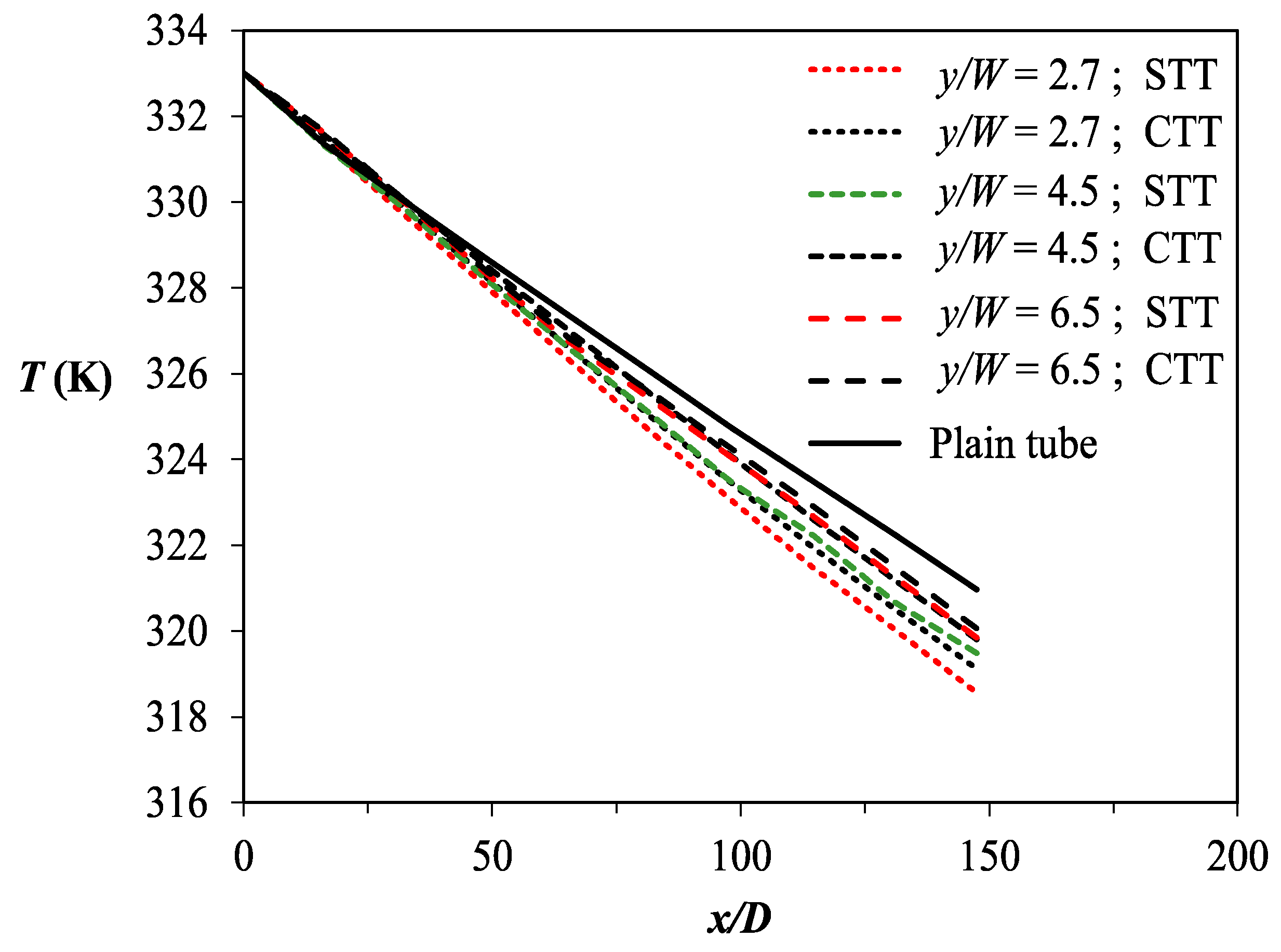
Figure 7.
Friction factor for various CTTs and STTs.

Figure 8.
Contour plots of velocity in inner tube at axial locations x/D of 3.49, 48.95, 97.90, and 143.35 at Re = 14,100 for (a) PT, (b) y/W = 2.7 CTT, (c) y/W = 4.5 CTT, (d) y/W = 6.5 CTT, (e) y/W = 2.7 STT, (f) y/W = 4.5 STT, and (g) y/W = 6.5 STT.
Figure 8.
Contour plots of velocity in inner tube at axial locations x/D of 3.49, 48.95, 97.90, and 143.35 at Re = 14,100 for (a) PT, (b) y/W = 2.7 CTT, (c) y/W = 4.5 CTT, (d) y/W = 6.5 CTT, (e) y/W = 2.7 STT, (f) y/W = 4.5 STT, and (g) y/W = 6.5 STT.
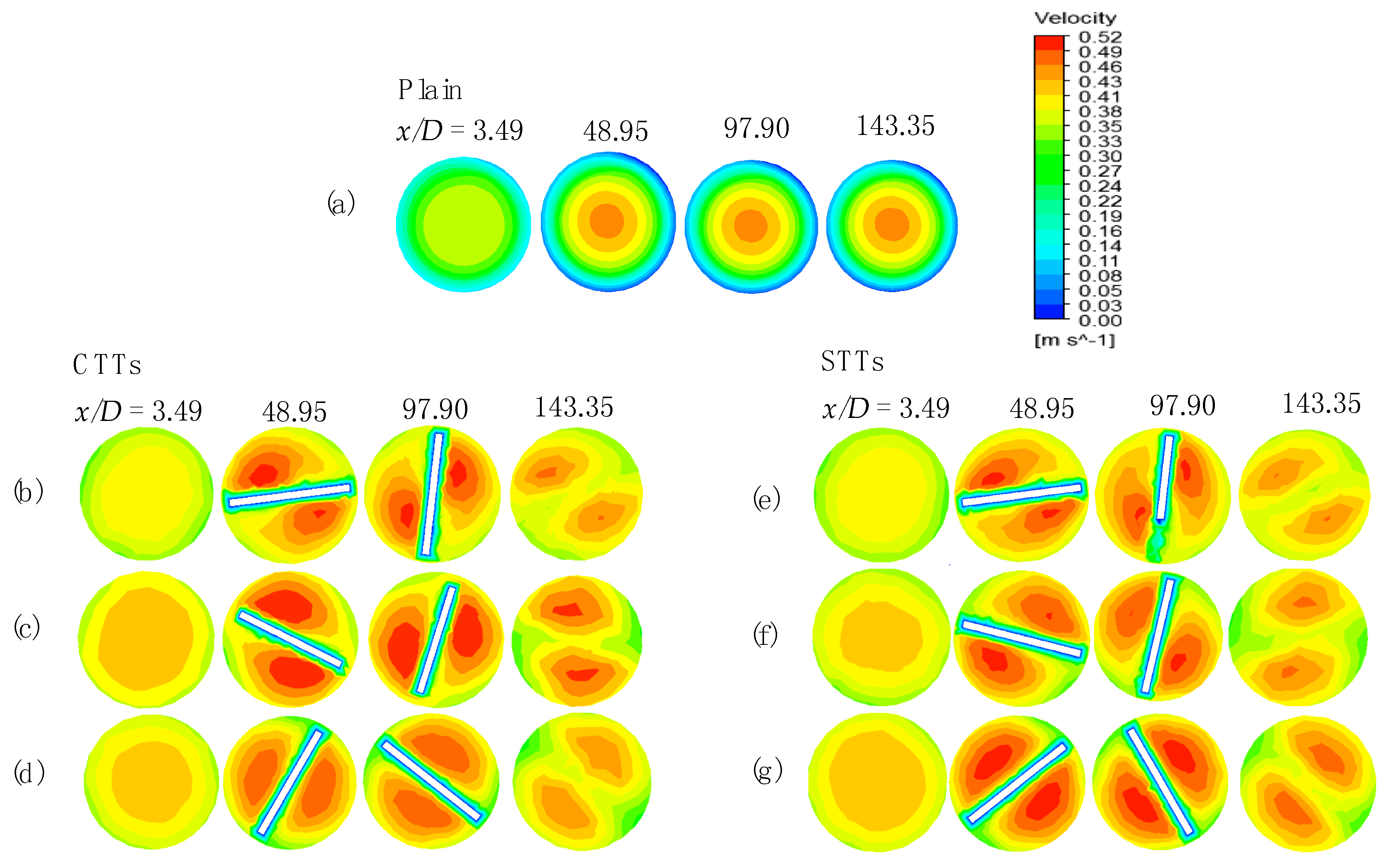
Figure 9.
Thermal performance for various CTTs and STTs.


Table 1.
Thermo-physical properties of the hot and cold water at inner and outer tube inlets [15].
Table 1.
Thermo-physical properties of the hot and cold water at inner and outer tube inlets [15].
| Fluid | Temperature [K] | Heat Capacity Cp [kJ/kg⋅K] | Dynamic Viscosity μ [kg/m⋅s] | Thermal Conductivity k [W/m⋅K] | Density ρ [kg/m3] | Prandtl Number Pr |
|---|---|---|---|---|---|---|
| Hot water | 333.15 | 4.185 | 4.67(10−4) | 0.654 | 983.3 | 2.99 |
| Cold water | 300.15 | 4.178 | 8.52(10−4) | 0.613 | 997 | 5.81 |
© 2019 by the authors. Licensee MDPI, Basel, Switzerland. This article is an open access article distributed under the terms and conditions of the Creative Commons Attribution (CC BY) license (http://creativecommons.org/licenses/by/4.0/).
Share and Cite
MDPI and ACS Style
Wijayanta, A.T.; Pranowo; Mirmanto; Kristiawan, B.; Aziz, M. Internal Flow in an Enhanced Tube Having Square-cut Twisted Tape Insert. Energies 2019, 12, 306. https://doi.org/10.3390/en12020306
AMA Style
Wijayanta AT, Pranowo, Mirmanto, Kristiawan B, Aziz M. Internal Flow in an Enhanced Tube Having Square-cut Twisted Tape Insert. Energies. 2019; 12(2):306. https://doi.org/10.3390/en12020306
Chicago/Turabian StyleWijayanta, Agung Tri, Pranowo, Mirmanto, Budi Kristiawan, and Muhammad Aziz. 2019. "Internal Flow in an Enhanced Tube Having Square-cut Twisted Tape Insert" Energies 12, no. 2: 306. https://doi.org/10.3390/en12020306
Note that from the first issue of 2016, this journal uses article numbers instead of page numbers. See further details here.