Robust Nonlinear Predictive Current Control Techniques for PMSM

College of Electrical and Information Engineering, Hunan University, Changsha 410082, China
*
Author to whom correspondence should be addressed.
Energies 2019, 12(3), 443; https://doi.org/10.3390/en12030443
Submission received: 30 November 2018
/
Revised: 29 December 2018
/
Accepted: 16 January 2019
/
Published: 30 January 2019
(This article belongs to the Special Issue Permanent Magnet Synchronous Machines)
Abstract
:This paper proposes a robust nonlinear predictive current control (RNPCC) method for permanent magnet synchronous motor (PMSM) drives, which can optimize the current control loop performance of the PMSM system with model parameter perturbation. First, the disturbance caused by parameter perturbation was considered in the modeling of PMSM. Based on this model, the influence of parameter perturbation on the conventional predictive current control (PCC) was analyzed. The composite integral terminal sliding mode observer (SMO) was then designed to estimate the disturbance caused by the parameter perturbation in real time. Finally, a RNPCC method is developed without relying on the mathematical model of PMSM, which can effectively eliminate the influence of parameter perturbation by injecting the estimated disturbance value. Simulations and experiments verified that the proposed RNPCC method was able to remove the current error caused by the parameter perturbation during steady state operation.
1. Introduction
Field-oriented control (FOC) have been widely used in permanent magnet synchronous motor (PMSM) drives due to the fast and fully decoupled control of torque and flux [1,2,3,4]. In a FOC-based PMSM drive, the inner double-loop control is usually adopted. The internal current loop is designed for current tracking, while the external speed loop regulates the rotor speed [5]. The dynamic response and stability of the internal current loop are the key factors that determine the performance of the whole drive system.
To achieve a high performance PMSM drive system, the predictive current control (PCC) method has been adopted in a wide range of applications [6]. The PCC can calculate the required command voltage based on the discrete mathematical model of PMSM, and achieves an accurate current tracking [7]. Furthermore, the PCC improves the bandwidth of current control loops and the dynamic performance of motors theoretically [8,9,10]. However, the performance of PCC is largely dependent on the accuracy of the PMSM model, which means that the parameter perturbation will deteriorate its performance.
Neglecting the parameter perturbation in the PCC design results in a significant steady-state current error and oscillation. To overcome this shortage, a robust PCC technique is proposed in [11], which can reduce the current error caused by motor parameter variation. In [12], an extension of the PCC method is presented to improve the prediction accuracy, which can not only reduce the current ripple, but also improve the robustness of the PCC against parameter perturbation. In [13], a real-time predictive control scheme with a parallel integral loop is presented for Pulse Width Modulation (PWM) nverter-fed PMSM drives, which can compensate for the variations in motor parameters. However, to achieve an acceptable transient response without overshooting, the integral gain needs to be properly designed.
Some other robust PCC methods based on a disturbance observer have been investigated to enhance the predictive control performance under parameter perturbations. The authors in [14] propose a flux immunity robust PCC for PMSM drives which can operate without knowing the rotor flux. In order to avoid the divergence caused by stator inductance mismatch, the proposed robust PCC adopts an extended state observer to enhance inductance robustness. In [15], a composite predictive control method based on stator current and a disturbance observer is developed, which can achieve perfect current control performance of the PMSM with model parameter mismatch. In [16], a simple disturbance observer is designed to increase the robustness of the proposed deadbeat predictive control algorithm against parameter uncertainties of the Permanent Magnetic Synchronous Generator (PMSG). In [17], a robust fault-tolerant predictive current control algorithm is proposed based on a composite observer, which can enhance robustness against parameter perturbation and permanent magnet demagnetization by adding compensation voltage. In [18], a continuous-time offset-free model predictive control approach based on a disturbance observer is developed for a general disturbed system, which can correct the errors caused by disturbances and uncertainties. By designing a novel sliding surface based on the disturbance estimation, a disturbance observer method was developed to counteract the mismatched disturbance in [19]. In [20], a generalized nonlinear model predictive control augmented with a disturbance observer is proposed, which can solve the disturbance problem of nonlinear systems. The disturbance observers in the aforementioned methods are able to achieve precise disturbance compensation. Moreover, it is possible to enhance robustness against parameter perturbation. In industrial applications, the flux linkage parameter is often accompanied by a change of inductance parameter. However, it is difficult to use these disturbance observers to simultaneously compensate for the resistance, inductance and flux linkage parameter perturbation.
In order to eliminate motor parameter perturbation effects, with improved robustness against inductance and flux linkage parameter mismatch, this paper proposes a robust nonlinear predictive current control (RNPCC) algorithm, which has three main contributions. Firstly, the influence of parameter perturbation on the PCC was analyzed. PCC is mostly sensitive to flux linkage and inductance parameters, whereas the influence of the resistance parameter can be ignored. Secondly, a composite integral terminal observer based on the Luenberger observer and sliding mode observer (SMO) was designed, which can estimate the external disturbance caused by parameter perturbation. Thirdly, the proposed RNPCC with online disturbance estimation can overcome the weakness of the steady-state current error of the conventional PCC. Thus it can be readily applicable in practical engineering.
This paper is organized as follows. A nonlinear PMSM model is developed in Section 2. The influence of parameter perturbation on conventional PCC is analyzed in Section 3. The RNPCC method is proposed in Section 4. The composite integral terminal SMO is designed in Section 5. The simulations and experiments are set up in Section 6 and Section 7, respectively. Section 8 concludes this paper.
2. Nonlinear PMSM Model
Machine Model Description
The voltage equations of the PMSM in a synchronous rotating reference frame are written as in [10,21]:
where and denotes the d- and q-axis stator voltages, respectively; and present the d- and q-axis currents, respectively; , , and denotes the nominal values of the stator resistance, the d-axis inductance and the q-axis inductance, respectively; is the electrical rotor speed; and is the flux linkage established by the permanent magnet.
For surface-mounted PMSM (SPMSM), . If we define , and , the voltage equations of the SPMSM are expressed as follows, according to (1), when parameter perturbations are considered.
where , , and are the nominal values and , , and are the perturbation values of the corresponding model parameters; and and represent the disturbances caused by parameter perturbations. The and can be expressed as:
According to (2), the nonlinear mathematical model of SPMSM is established as:
where , , , and are state variables, system inputs, system outputs, and disturbances, respectively.
The coefficient matrixes of the state equations are:
3. Parameter Sensitivity Analysis of Conventional PCC
According to [15], the output voltage vectors of conventional PCC are expressed by:
where, is the sampling period: , , , , , .
When the sampling period () is small enough, we can obtain . According to (2), the discrete model of the SPMSM under parameter perturbations can be expressed by,
where: .
The conventional PCC method belongs to one beat delay control, and the voltage vector is applied to the SPMSM at the moment. Therefore, substituting (5) into (6) yields:
with,
where and are the d- and q-axis current errors, respectively.
The stationary equations are given as follows [22]:
In this paper, id is set to 0. Thus, the current on d-axis is neglected. Combining (3), (8) and (9), the current errors on the d- and q-axis can be simplified as:
From (10), the d- and q-axis current errors can be deduced when there is a resistance parameter error between actual value and nominal value :
Similarly, the d- and q-axis current errors can be obtained by (12) under flux linkage parameter error :
The d- and q-axis current errors can be obtained by (13) under inductance parameter error :
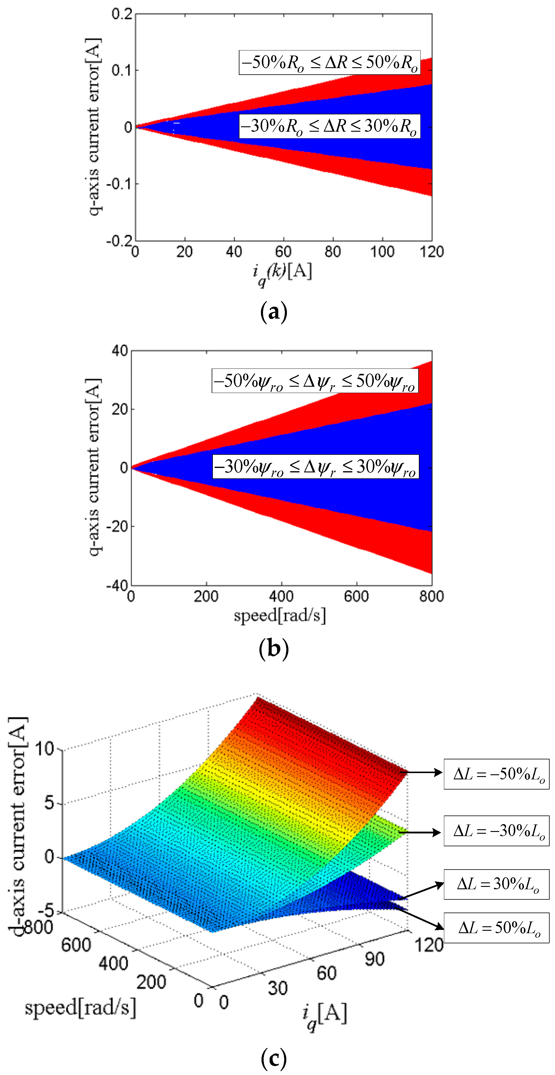
The motor parameters are provided in Table 1. According to (11), (12), and (13) the d- and q-axis current errors are plotted, as in Figure 1. Figure 1a shows the q-axis current error under resistance parameter mismatch. It can be observed from Figure 1a and Equation (11) that the resistance parameter perturbation does not affect the d-axis current, and resistance parameter perturbation has little effect on the q-axis current. Figure 1b shows the q-axis current error under flux linkage parameter mismatch. From Figure 1b and Equation (12), it is known that the flux linkage parameter mismatch does not affect the d-axis current, but the influence on the q-axis current is very strong. Figure 1c shows the d-axis current error under inductance parameter mismatch. From Figure 1c and Equation (13), it is known that the q-axis current error is zero, and the d-axis current error increases with the increase of the speed and q-axis current. Through the above analysis, the inductance and flux linkage parameter mismatches deteriorate the performance of the PCC, while the influence of the resistance parameter mismatch can be ignored.
4. Design of the RNPCC
4.1. Design of the Optimal Control Law
The reference value and predictive value of the output currents are respectively defined as:
To simplify the calculations, these two values are expanded to 1th-order Taylor series:
where is the time constant: , , , .
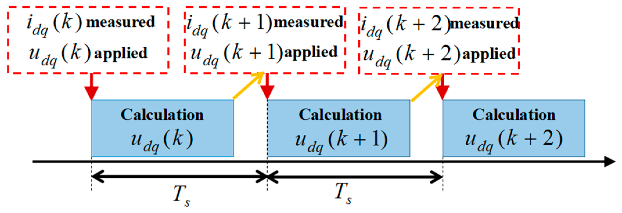
In Figure 2, the control sequence logic diagram of the proposed RNPCC method is illustrated in a discrete-time framework. The design of the cost function depends on the requirements of the control system performance. The servo control system belongs to the tracking control system, and it is hoped that the output can track the input reference accurately. Therefore, the cost function is defined as:
with
where:
Substituting (17) into (16), the cost function is written as:
where: , , , .
The constraint condition of the optimal control law is given by:
Substituting (18) into (19) yields:
Thus, the optimal control law can be obtained according to (19), as given by:
4.2. Design of the RNPCC
In order to improve the robustness against the parameter perturbation, a composite integral terminal SMO is designed. Taking and as the references of and , respectively, the predictive current controller is designed as:
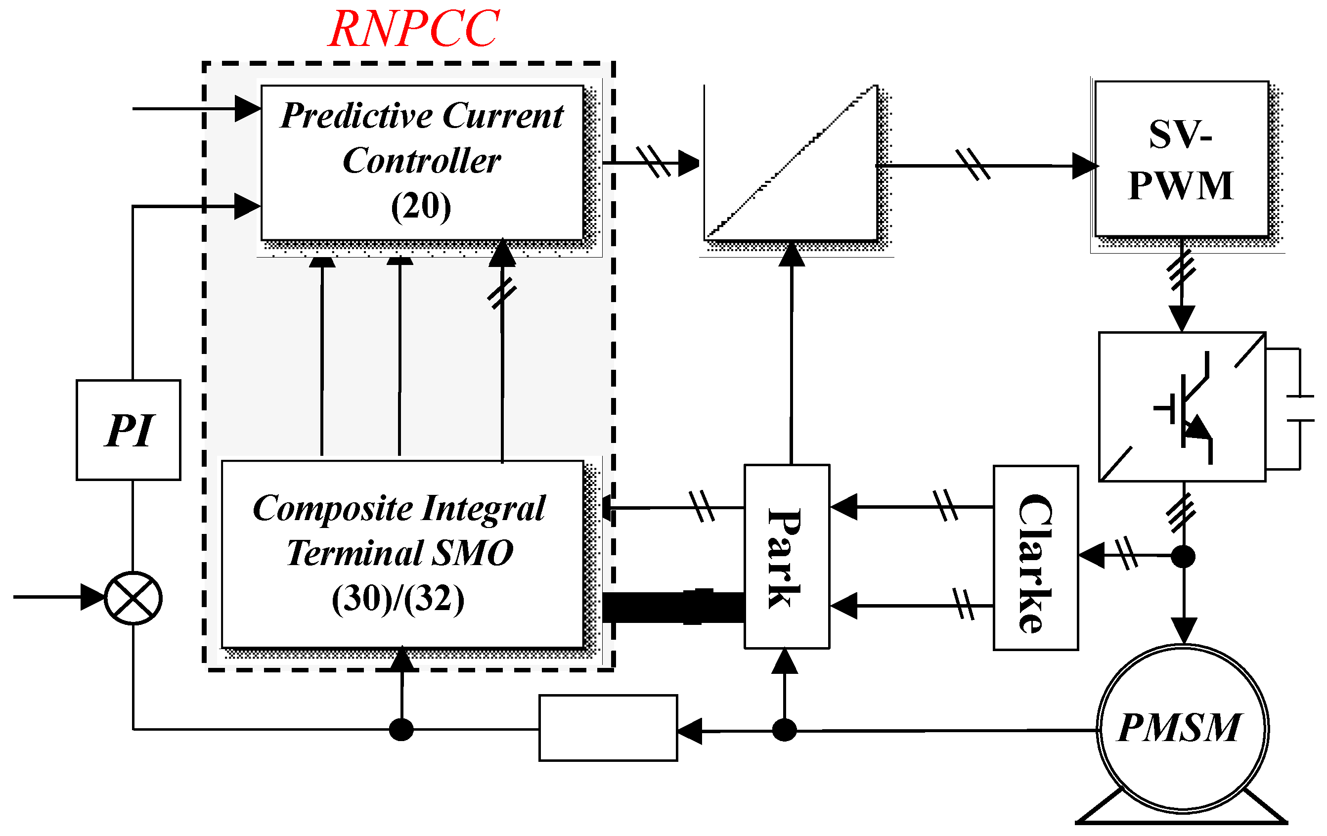
where , are the estimation values of , , respectively; , are the estimation values of , , respectively; and and are the output references of the RNPCC. The block diagram of RNPCC method with a composite integral terminal SMO is shown in Figure 3.
5. Design of the Composite Integral Terminal SMO
The key to realizing the RNPCC method is to estimate the disturbance caused by parameter perturbation. Based on (4), the composite integral terminal SMO is designed as:
where is the observed value of , is the designed gain matrix of Luenberger observer, is the sliding mode control function, , , and .
Consider the following integral terminal sliding surface vector:
In industrial applications, chattering suppression is necessary when designing observers because the chattering of the sign function easily causes the chattering of the system. Therefore, the hyperbolic tangent function with smooth continuity is used instead of the sin function. The hyperbolic tangent function is expressed as:
where , ; sgn( ) is the sign function; and is defined as:
Taking the time derivative for (24), and combining it with (4) and (23), the error equation of the composite integral terminal SMO can be obtained as:
To prevent the influence of the motor speed on the error equation, the gain matrix of the Luenberger observer must be designed as . Thus, Equation (27) can be simplified to:
Considering the integral terminal sliding surface Equation (24) and the error Equation (27), to guarantee the convergence of error , the sliding mode control function is designed:
where is a positive diagonal matrix, and is the observer sliding gain.
Consider the Lyapunov function candidate as follows:
Differentiating Equation (30) and combining with Equation (28) yields:
Applying Equations (29)–(31) yields:
In industrial applications, the disturbances should be bounded, that is, normal values exist, satisfying , . If the gain matrix of composite integral terminal SMO satisfies , , then . Therefore, the stability and convergence of the composite observer are guaranteed.
From (23), the composite integral terminal SMO can be represented by:
According to the sliding mode equivalent principle, when the system reaches the sliding mode surface, that is, , Equation (28) can be simplified to:
From (34), the estimated disturbances can be represented by:
With:
6. Simulations
The parameters of SPMSM used in the simulation are given in Table 1. The sampling frequency for current control loop was 10 kHz; the proposed composite integral terminal SMO parameters were , K1 = K2 = K3 = 5000, and Ks1 = Ks2 = Ks3 = 100, respectively. At 0 s, the speed reference increased from 0 to 800 rad/s, and the load torque increased suddenly from no-load to rated load.
6.1. Performance Comparison of Conventional PCC and Proposed RNPCC under Inductance Parameter Perturbation
In this simulation, the inductance parameter perturbation value was set to zero initially. At 0.5 s, changed to . The simulation results are shown in Figure 4 and Figure 5.
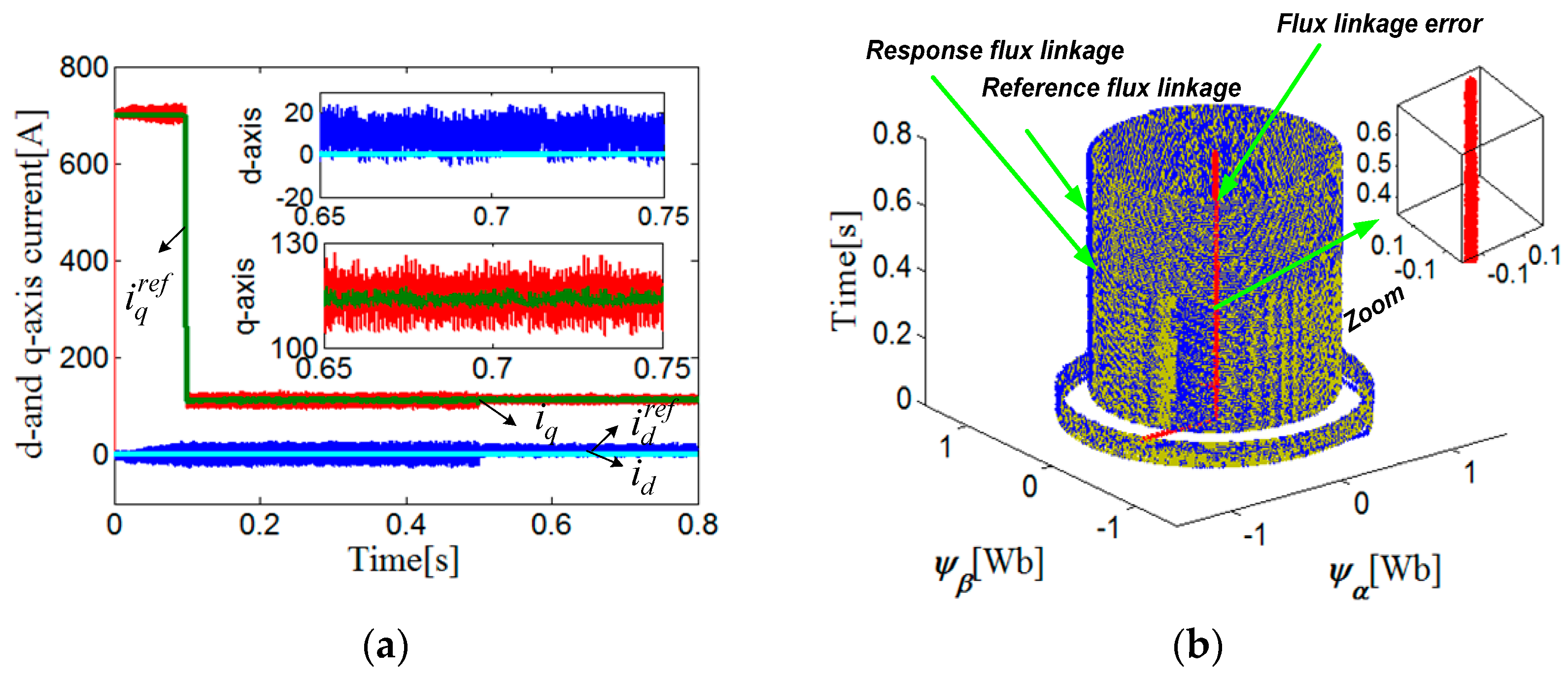
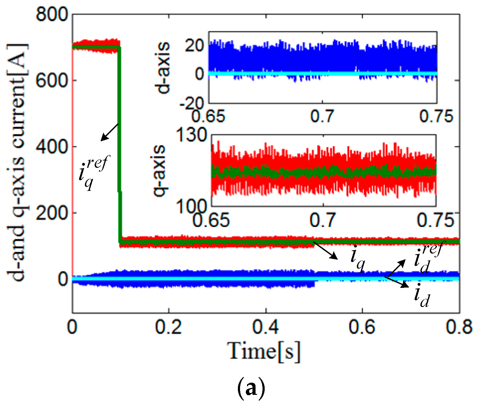
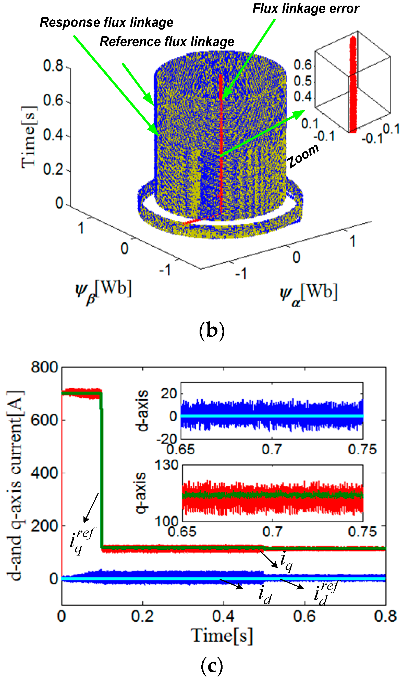
When taking the conventional PCC method, the d-axis current response value cannot track the current reference after 0.5 s, which is shown clearly in Figure 4a. The d-axis current response value was 11 A, which was bigger than its current reference, that is, 0 A, and the steady error was −11 A. The reason for this was that the conventional PCC depends on the inductance parameter of the motor. Figure 5c presents the simulation results of the disturbance estimation when using the RNPCC method. The results reflect that the proposed composite integral terminal SMO can accurately estimate the disturbance under inductance parameter perturbation. From Figure 5a, it can be seen that the current response can track its reference accurately by using the proposed composite integral terminal SMO. Figure 4b shows the three-dimension rotor flux trajectories of the conventional PCC method under inductance parameter perturbation. Figure 5b shows the three-dimensional rotor flux trajectories of the RNPCC method under inductance parameter perturbation. The influence of inductance perturbation on the α- and β-axis flux linkage can be neglected because of the small d-axis current error, which can be clearly seen in Figure 4b and Figure 5b.
6.2. Performance Comparison of Conventional PCC and Proposed RNPCC under Flux Linkage Parameter Perturbation
In this simulation, the flux linkage parameter perturbation value was set initially to zero. At 0.5 s, changed to . The simulation results are shown in Figure 6 and Figure 7.
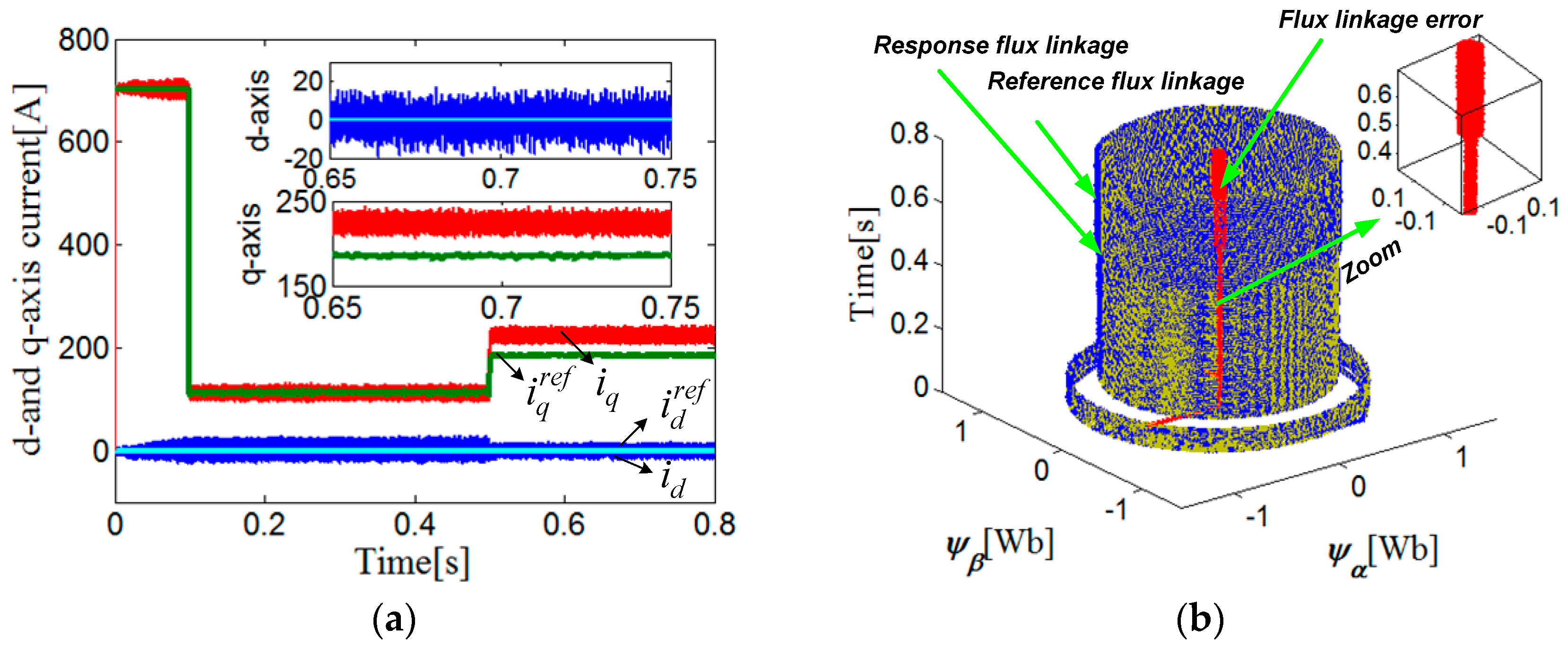
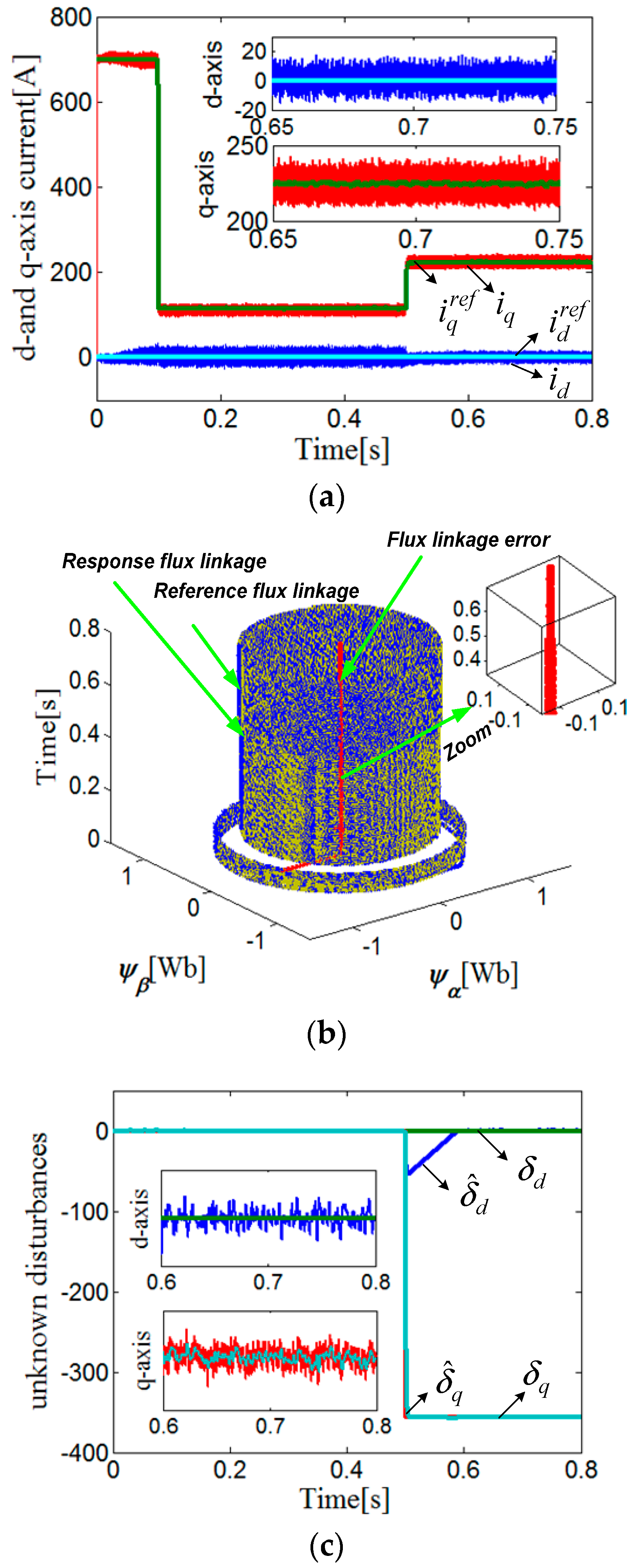
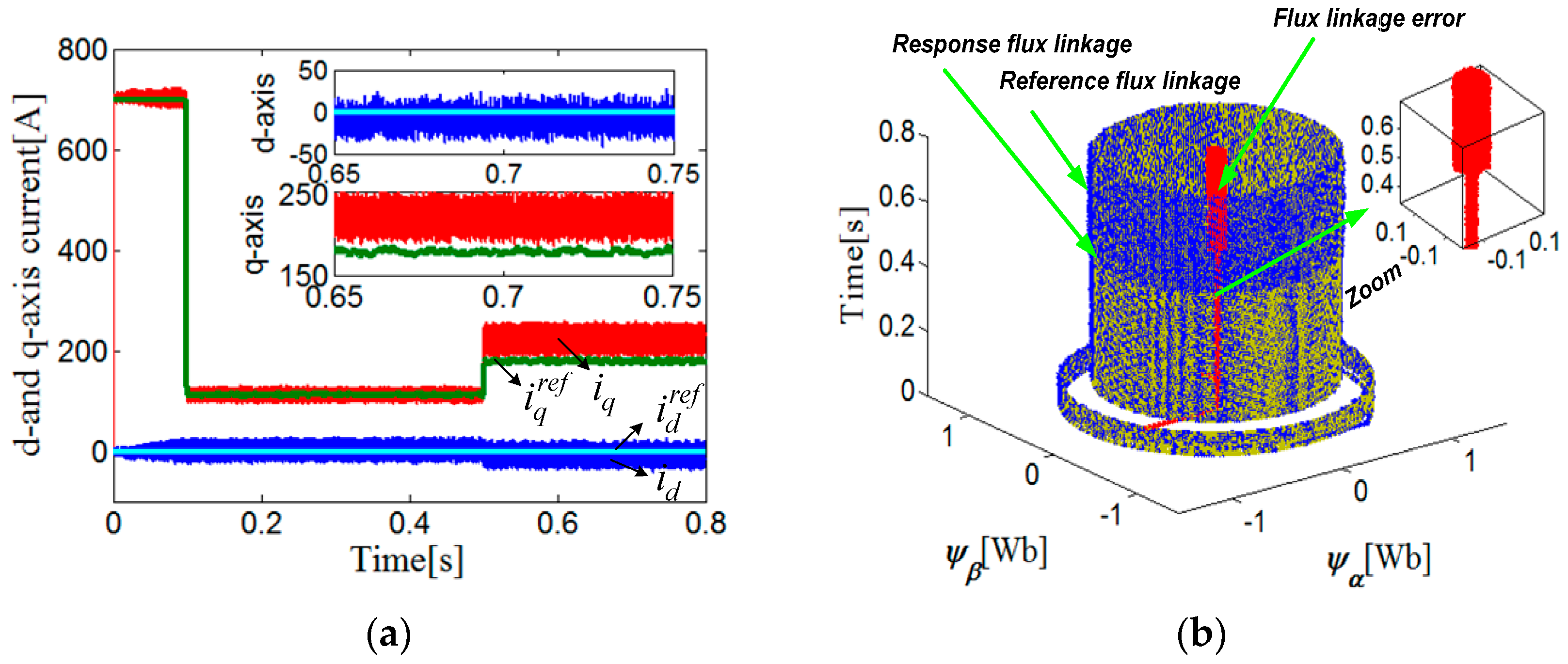
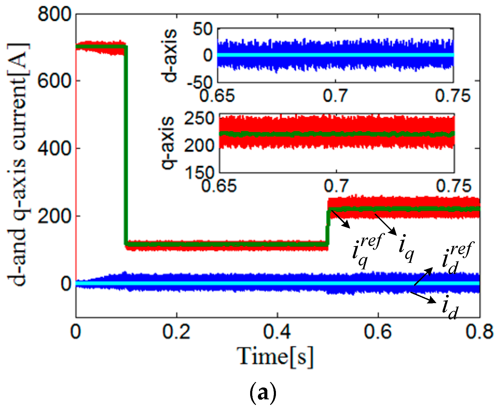
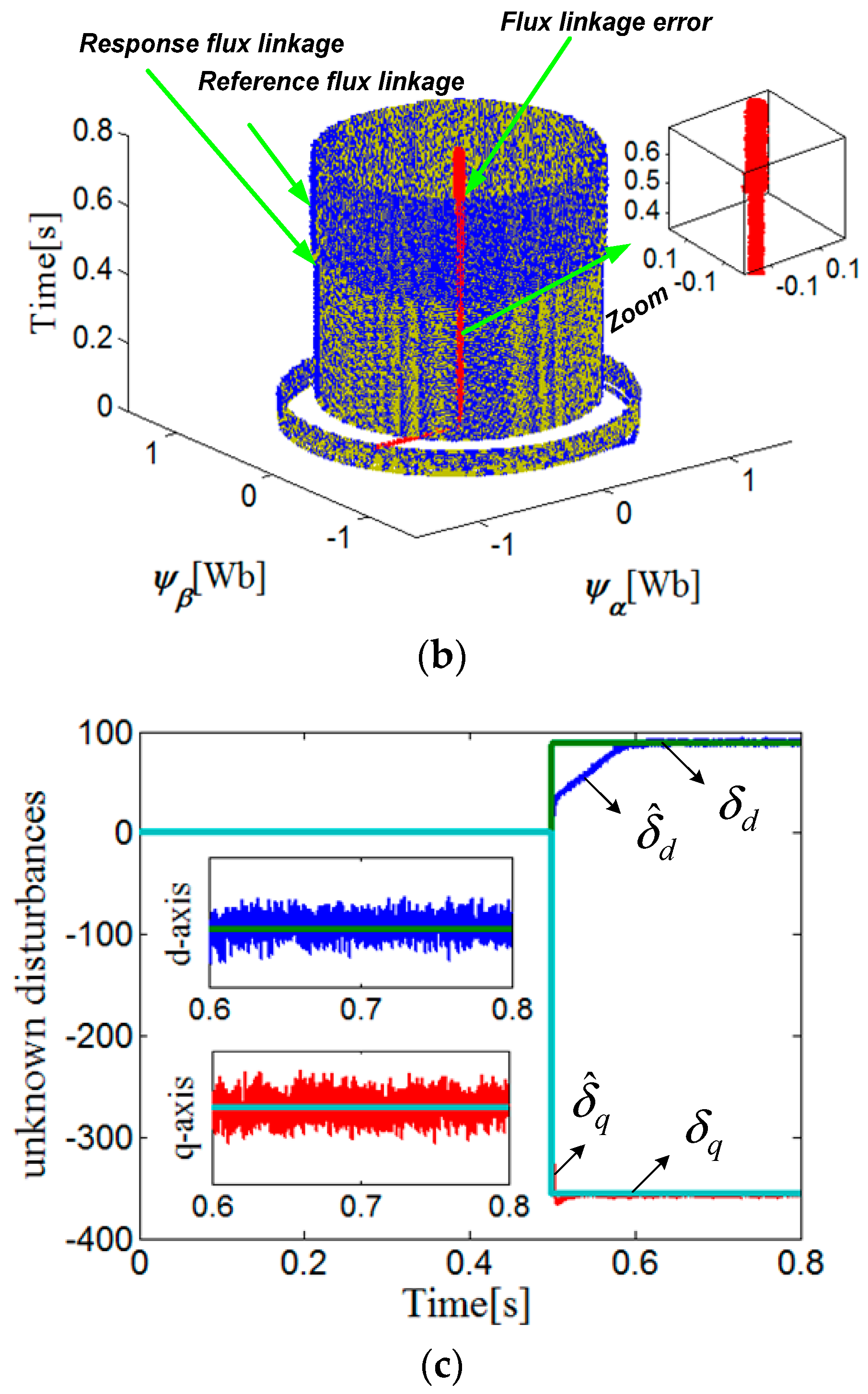
From Figure 6a, it is known that the q-axis current response values cannot track current references under flux linkage parameter perturbation when using the conventional PCC method. After 0.5 s, the q-axis current response value and reference value were respectively 225 A and 185 A, and the steady error was −40 A. When using the RNPCC method, the disturbance was accurately estimated using the proposed composite integral terminal SMO, as can be seen in Figure 7. From Figure 7a, it can be seen that the steady state current error can effectively be removed by injecting the estimated external disturbance value. Figure 6b shows the three-dimensional rotor flux trajectories of the conventional PCC method under flux linkage parameter perturbation. Figure 7b shows the three-dimensional rotor flux trajectories of the RNPCC method under flux linkage parameter perturbation. Note that there are large α- and β-axis flux linkage errors when the flux linkage parameter is changed suddenly at 0.5 s. The reason for this is that the conventional PCC produces a large q-axis current steady error under flux linkage parameter perturbation.
6.3. Performance Comparison of Conventional PCC and Proposed RNPCC under Inductance and Flux Linkage Parameter Perturbation
In this simulation, the inductance and flux-linkage parameter perturbation values were both set to zero initially, and changed to and at 0.5 s, respectively. The simulation results are shown in Figure 8 and Figure 9.
From Figure 8a, it can be seen that the d- and q-axis current steady error were respectively 12 A and −43 A after 0.5 s when using the conventional PCC, which were larger than those of simulations (a) and (b). The disturbance caused by the inductance and flux linkage parameter perturbations was also able to be accurately estimated when using the RNPCC, as can be seen in Figure 9. Furthermore, the d-axis and q-axis current steady error was effectively removed using the proposed composite integral terminal SMO. Figure 8b shows the three-dimensional rotor flux trajectories of the conventional PCC method under inductance and flux linkage parameter perturbation. Figure 9b shows the three-dimensional rotor flux trajectories of the RNPCC method under inductance and flux linkage parameter perturbation. The errors of α- and β-axis flux linkage were more serious than those of simulation (b) under inductance and flux linkage parameter perturbations, while still being nearly zero when using the RNPCC, as is clearly shown in Figure 8b and Figure 9b. The Comparison of the current tracking between the conventional PPC and RNPCC are provided in Table 2.
7. Experimental Results
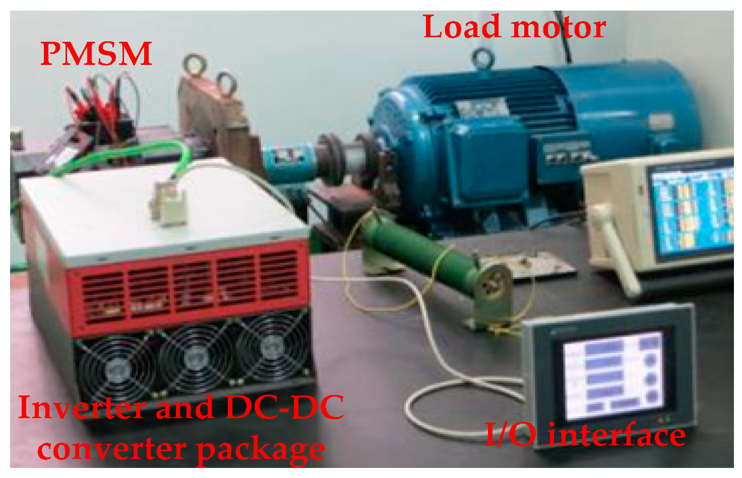
To further verify the proposed RNPCC method, experiments were conducted using a PMSM laboratory platform, as is shown in Figure 10. It was composed of two motors (drive and load machines). The per-unit (p.u.) values of 10kW PMSM parameters are consistent with the simulation models. The current clamp was used to detect the current during the experiment. A torque sensor (Beijing Sanjing Creation Science & technology Group Co., LTD., Beijing, China) was used to detect motor torque. Finally, the experimental results were obtained by Tek oscilloscope.
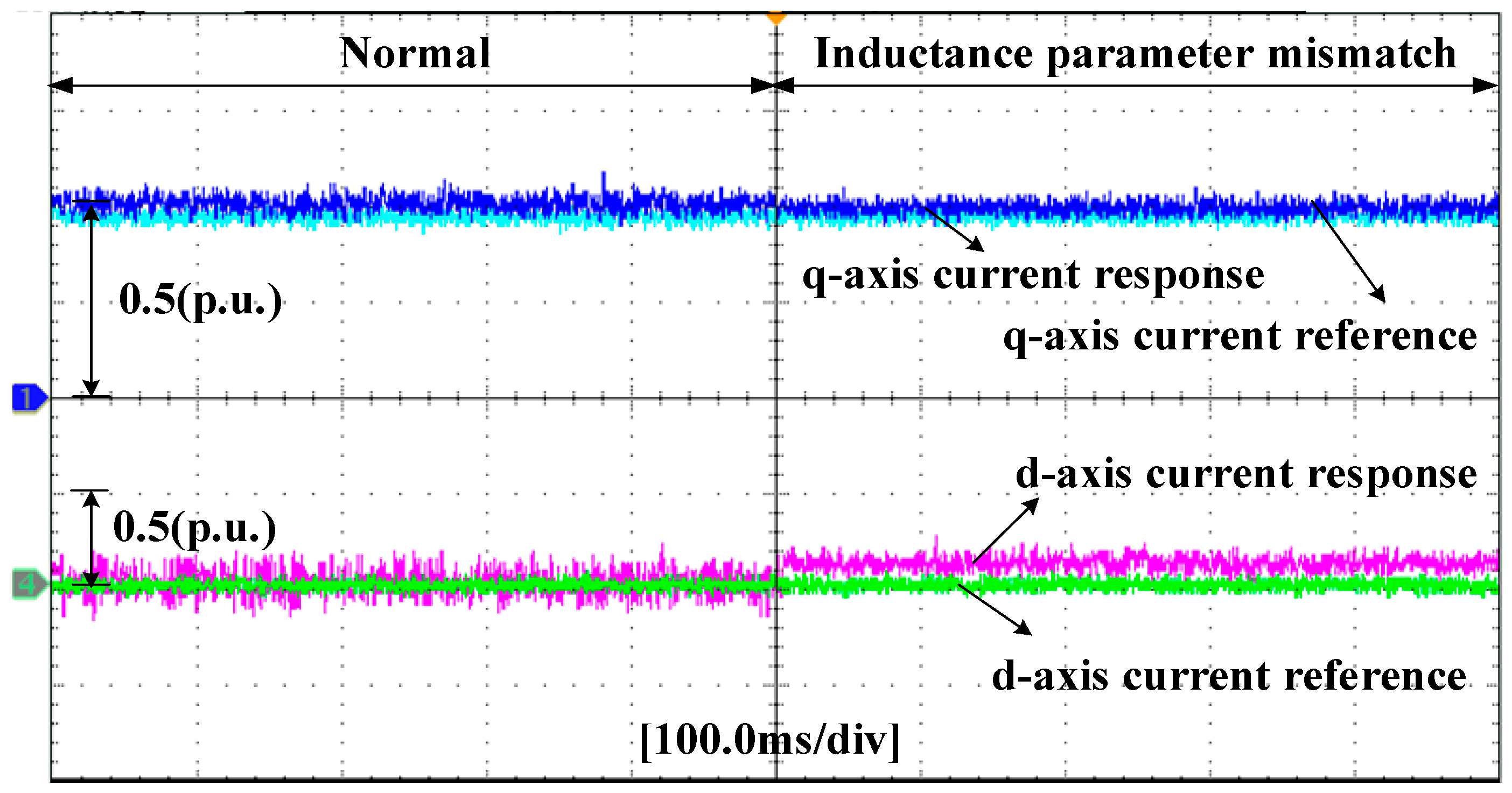
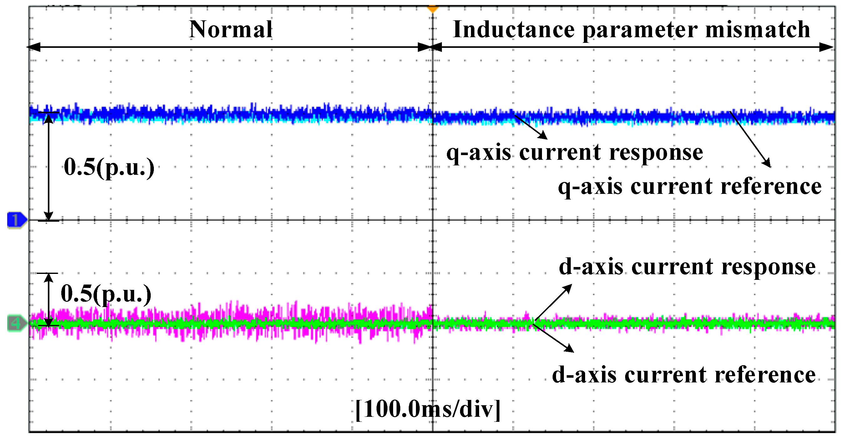
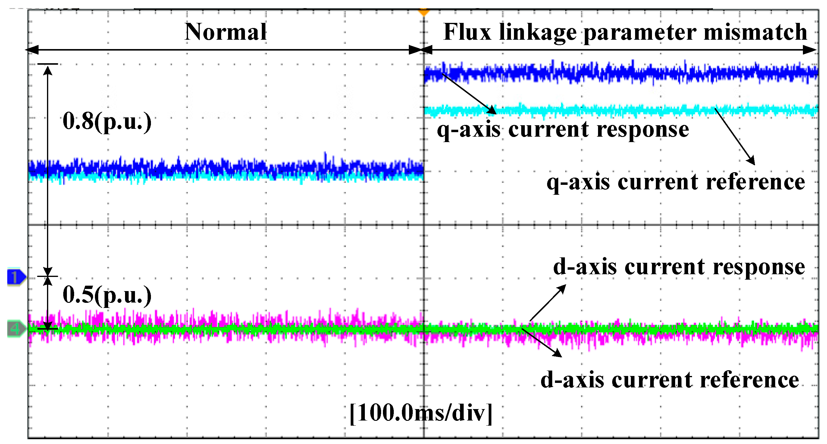
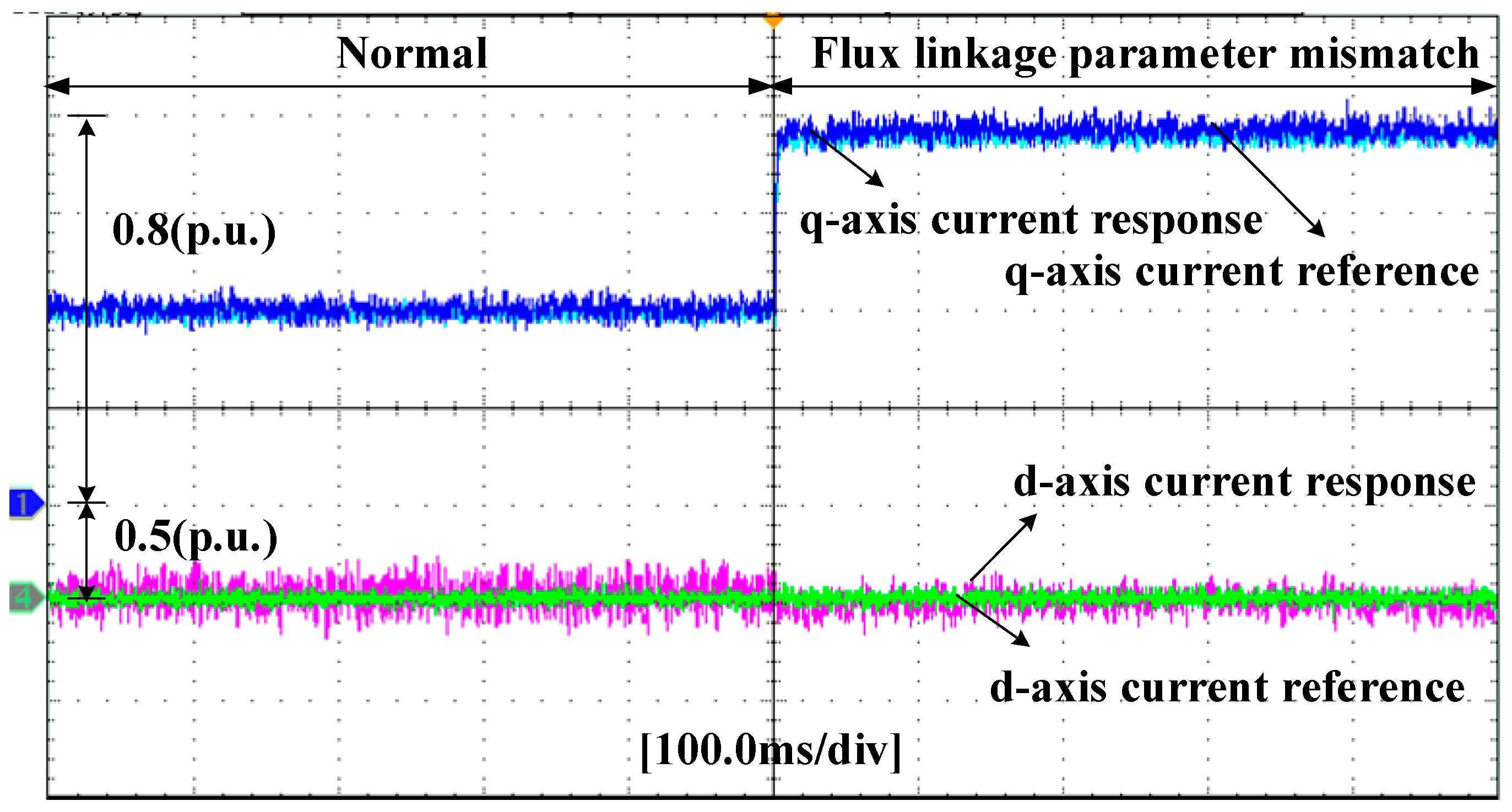
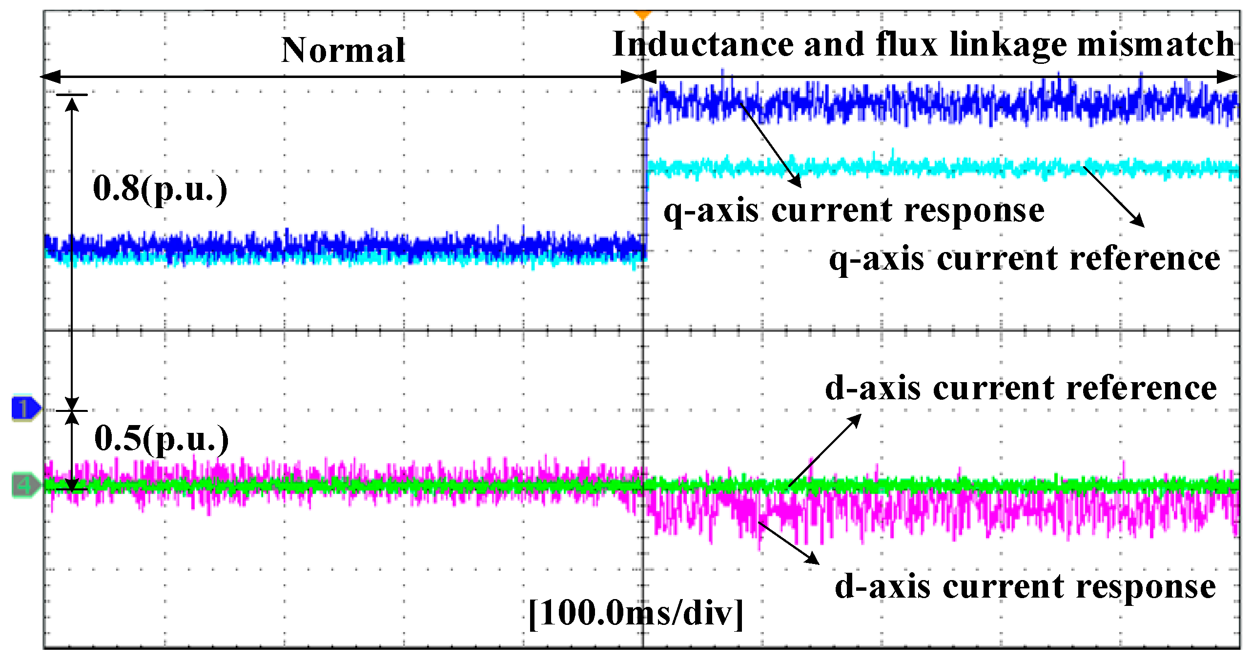
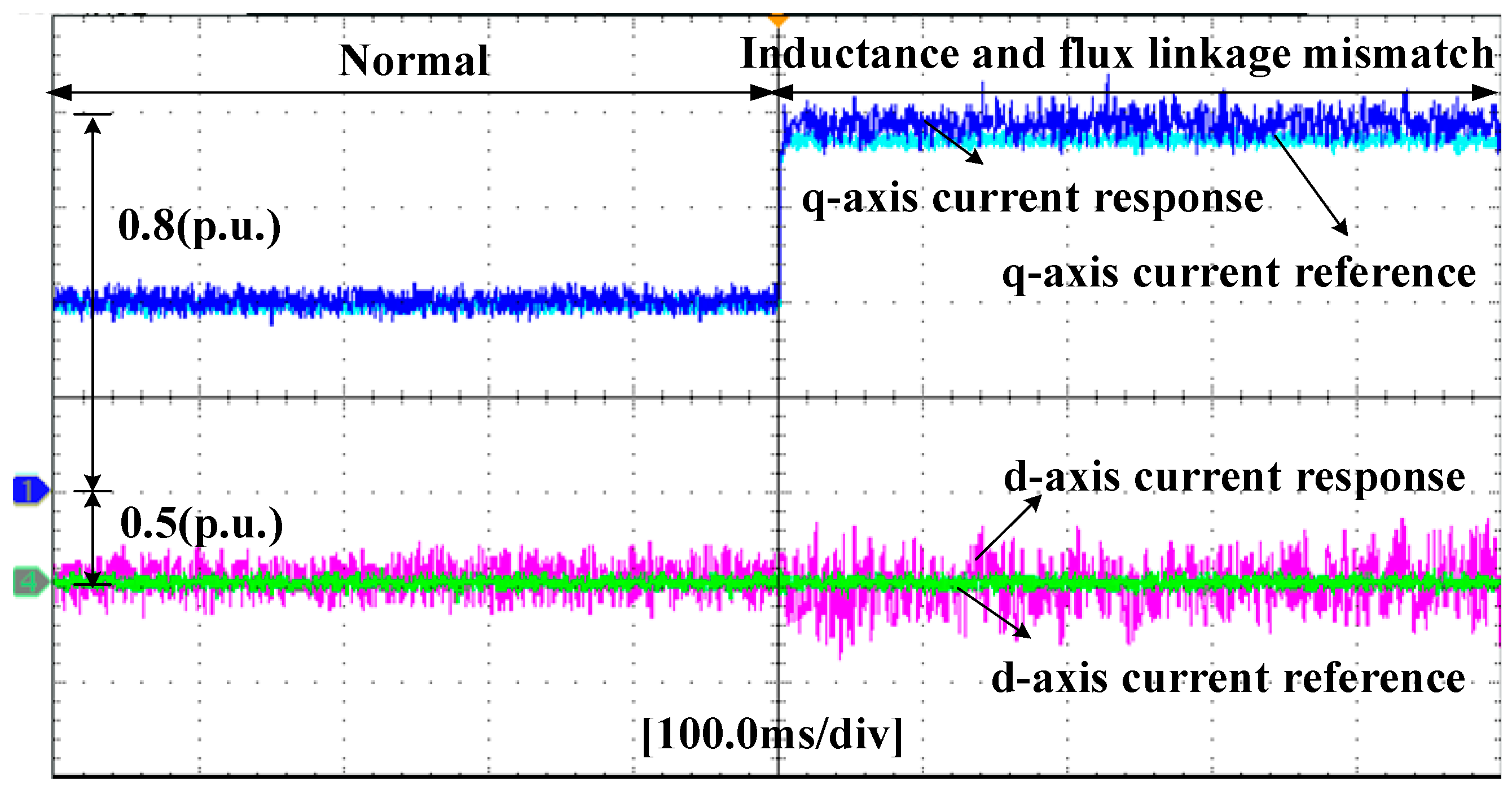
The experimental results of the conventional PCC and proposed RNPCC under inductance parameter perturbation are shown in Figure 11 and Figure 12, respectively. From Figure 11, it can be seen that the d-axis current value was greater than the reference value, but the inductance parameter perturbation had little effect on the q-axis current when using the conventional PCC. Figure 12 shows that the d-axis current steady state error could be removed by using the proposed RNPCC. Figure 13 and Figure 14 show the control performance comparisons under flux linkage parameter mismatch. Figure 13 shows that the flux linkage parameter mismatch exerted an effect on the q-axis current response in the conventional PCC method. The q-axis current response value was greater than the current reference under flux linkage parameter mismatch. When using the RNPCC method, it can be observed from Figure 14 that the q-axis current response could track the current reference accurately and quickly. Figure 15 and Figure 16 show the control performance comparisons under inductance and flux linkage parameter mismatch. From Figure 15, it can be seen that neither the d-axis nor the q-axis current response could track the current reference. The q-axis value of the current response was greater than the current reference, whereas the d-axis current response value was less than the current reference when using the conventional PCC. Figure 16 shows that the proposed RNPCC could remove the steady state current error caused by the inductance and flux linkage parameter perturbations during steady state operation.
8. Conclusions
This paper proposed an RNPCC method based on a composite integral terminal SMO for current loop of the PMSM control system, without relying on the mathematical mode. The steady state current tracking errors caused by parameter perturbations were eliminated by the introduction of the disturbance estimation into the proposed control law. Moreover, the proposed RNPCC was able to effectively guarantee the control precision of the current loop regardless of the inductance and flux linkage parameter perturbations. The simulation and experimental results validated the performance of the proposed RNPCC. Compared with the traditional PCC, the proposed RNPCC shows its superiority in control precision and disturbance rejection. Additionally, the proposed RNPCC presents strong robustness and an excellent dynamic response in the case of parameter perturbations, where the weakness of the conventional PCC was successfully overcome. However, the proposed control method ignores the effect caused by rotor position detection error. The rotor position of the PMSM may deviate from the true position due to the position detection device fault, which can provide a mistaken response current to the proposed control method. As a result, the control performance of the proposed method deteriorated. A further research direction is to propose a novel robust predictive control algorithm to overcome the influence of inaccurate rotor position detection.
Author Contributions
M.L., G.W. and D.L. designed the proposed control strategy, M.L., G.W. and D.L. conducted experimental works, modeling and simulation, S.H. and F.R. gave help of paper writing.
Funding
This work was supported in part by the National Key R&D Program of China (2016YFF0203400).
Conflicts of Interest
The authors declare no conflicts of interest.
References
- Consoli, A.; Scarcella, G.; Testa, A. Slip-frequency detection for indirect field-oriented control drives. IEEE Trans. Ind. Electron. 2004, 40, 194–201. [Google Scholar] [CrossRef]
- Qian, W.; Panda, S.K.; Xu, J.X. Torque ripple minimization in PM synchronous motors using iterative learning control. IEEE Trans. Power Electron. 2004, 19, 272–279. [Google Scholar] [CrossRef]
- Wang, B.; Chen, X.; Yu, Y.; Wang, G.; Xu, D. Robust predictive current control with online disturbance estimation for induction machine drives. IEEE Trans. Power Electron. 2017, 32, 4663–4674. [Google Scholar] [CrossRef]
- Zoghlami, M.; Kadri, A.; Bacha, F. Analysis and Application of the Sliding Mode Control Approach in the Variable-Wind Speed Conversion System for the Utility of Grid Connection. Energies 2018, 11, 720. [Google Scholar] [CrossRef]
- Stojic, D.M.; Milinkovic, M.; Veinovic, S.; Klasnic, I. Stationary frame induction motor feed forward current controller with back EMF compensation. IEEE Trans. Power Electron. 2015, 30, 1356–1366. [Google Scholar] [CrossRef]
- Yan, L.; Dou, M.; Hua, Z. Disturbance Compensation-Based Model Predictive Flux Control of SPMSM with Optimal Duty Cycle. IEEE J. Emerg. Sel. Top. Power Electron. 2018. [Google Scholar] [CrossRef]
- Carpiuc, S.C.; Lazar, C. Fast real-time constrained predictive current control in permanent magnet synchronous machine-based automotive traction drives. IEEE Trans. Tran. Electrif. 2015, 1, 326–335. [Google Scholar] [CrossRef]
- Cortes, P.; Rodriguez, J.; Silva, C.; Flores, A. Delay Compensation in Model Predictive Current Control of a Three-Phase Inverter. IEEE Trans. Ind. Electron. 2012, 59, 1323–1325. [Google Scholar] [CrossRef]
- Lim, C.S.; Levi, E.; Jones, M.; Rahim, N.A.; Hew, W.P. FCSMPC- Based Current Control of a Five-Phase Induction Motor and its Comparison with PI-PWM Control. IEEE Trans. Ind. Electron. 2016, 61, 149–163. [Google Scholar] [CrossRef]
- Chen, Z.; Qiu, J.; Jin, M. Prediction-Error-Driven Position Estimation Method for Finite Control Set Model Predictive Control of Interior Permanent Magnet Synchronous Motors. IEEE J. Emerg. Sel. Top. Power Electron. 2018. [Google Scholar] [CrossRef]
- Wipasuramonton, P.; Zhu, Z.Q.; Howe, D. Predictive current control with current-error correction for PM brushless AC drives. IEEE Trans. Ind. Appl. 2006, 42, 1071–1079. [Google Scholar] [CrossRef]
- Siami, M.; Khaburi, D.A.; Abbaszadeh, A.; Rodríguez, J. Robustness improvement of predictive current control using prediction error correction for permanent-magnet synchronous machines. IEEE Trans. Ind. Electron. 2016, 63, 3458–3466. [Google Scholar] [CrossRef]
- Le-Huy, H.; Slimani, K.; Viarouge, P. Analysis and implementation of a real-time predictive current controller for permanent-magnet synchronous servo drives. IEEE Trans. Ind. Electron. 1994, 41, 110–117. [Google Scholar] [CrossRef]
- Yang, M.; Lang, X.; Long, J.; Xu, D. Flux immunity robust predictive current control with incremental model and extended state observer for PMSM drive. IEEE Trans. Power Electron. 2017, 32, 9267–9279. [Google Scholar] [CrossRef]
- Zhang, X.; Hou, B.; Mei, Y. Deadbeat Predictive Current Control of Permanent-Magnet Synchronous Motors with Stator Current and Disturbance Observer. IEEE Trans. Power Electron. 2017, 32, 3818–3834. [Google Scholar] [CrossRef]
- Abdelrahem, M.; Hackl, C.M.; Zhang, Z.; Kennel, R. Robust Predictive Control for Direct-Driven Surface-Mounted Permanent-Magnet Synchronous Generators Without Mechanical Sensors. IEEE Trans. Energy Conv. 2018, 33, 179–189. [Google Scholar] [CrossRef]
- Zhang, C.; Wu, G.; Fei, R.; Feng, J.H.; Jia, L. Robust Fault-Tolerant Predictive Current Control for Permanent Magnet Synchronous Motors Considering Demagnetization Fault. IEEE Trans. Ind. Electron. 2018, 65, 5324–5334. [Google Scholar] [CrossRef]
- Yang, J.; Zheng, W.X.; Li, S.; Wu, B.; Cheng, M. Design of a prediction-accuracy-enhanced continuous-time MPC for disturbed systems via a disturbance observer. IEEE Trans. Ind. Electron. 2015, 62, 5807–58164. [Google Scholar] [CrossRef]
- Yang, J.; Li, S.; Yu, X. Sliding-mode control for systems with mismatched uncertainties via a disturbance observer. IEEE Trans. Ind. Electron. 2013, 60, 160–169. [Google Scholar] [CrossRef]
- Yang, J.; Zheng, W.X. Offset-free nonlinear MPC for mismatched disturbance attenuation with application to a static var compensator. IEEE Trans. Circuits Syst. II Express Br. 2014, 61, 49–53. [Google Scholar] [CrossRef]
- Hu, F.; Luo, D.; Luo, C.; Long, Z.; Wu, G. Cascaded Robust Fault-Tolerant Predictive Control for PMSM Drives. Energies 2018, 11, 3087. [Google Scholar] [CrossRef]
- Richter, J.; Doppelbauer, M. Predictive trajectory control of permanent-magnet synchronous machines with nonlinear magnetic. IEEE Trans. Ind. Electron. 2016, 63, 3915–3924. [Google Scholar] [CrossRef]
Figure 1.
d- and q-axis current errors under parameter mismatches. (a) q-axis current error under resistance parameter mismatch; (b) q-axis current error under flux linkage parameter mismatch; (c) d-axis current error under inductance parameter mismatch.
Figure 1.
d- and q-axis current errors under parameter mismatches. (a) q-axis current error under resistance parameter mismatch; (b) q-axis current error under flux linkage parameter mismatch; (c) d-axis current error under inductance parameter mismatch.

Figure 2.
Logic diagram of a beat delay compensation using robust nonlinear predictive current control (RNPCC) method.
Figure 2.
Logic diagram of a beat delay compensation using robust nonlinear predictive current control (RNPCC) method.

Figure 3.
Block diagram of the RNPCC method with composite integral terminal sliding mode observer (SMO) for permanent magnet synchronous motor (PMSM).
Figure 3.
Block diagram of the RNPCC method with composite integral terminal sliding mode observer (SMO) for permanent magnet synchronous motor (PMSM).

Figure 4.
Simulation results of the conventional predictive current control (PCC) method under inductance parameter perturbation. (a) d- and q-axis current responses and references; (b) three-dimension rotor flux trajectories.
Figure 4.
Simulation results of the conventional predictive current control (PCC) method under inductance parameter perturbation. (a) d- and q-axis current responses and references; (b) three-dimension rotor flux trajectories.

Figure 5.
Simulation results of the RNPCC method under inductance parameter perturbation. (a) d- and q-axis current responses and references; (b) three-dimensional rotor flux trajectories; (c) disturbance estimation results.
Figure 5.
Simulation results of the RNPCC method under inductance parameter perturbation. (a) d- and q-axis current responses and references; (b) three-dimensional rotor flux trajectories; (c) disturbance estimation results.


Figure 6.
Simulation results of the conventional PCC method under flux linkage parameter perturbation. (a) d- and q-axis current responses and references; (b) three-dimensional rotor flux trajectories.
Figure 6.
Simulation results of the conventional PCC method under flux linkage parameter perturbation. (a) d- and q-axis current responses and references; (b) three-dimensional rotor flux trajectories.

Figure 7.
Simulation results of the RNPCC method under flux linkage parameter perturbation. (a) d- and q-axis current responses and references; (b) three-dimension rotor flux trajectories; (c) disturbance estimation results.
Figure 7.
Simulation results of the RNPCC method under flux linkage parameter perturbation. (a) d- and q-axis current responses and references; (b) three-dimension rotor flux trajectories; (c) disturbance estimation results.

Figure 8.
Simulation results of the conventional PCC method under inductance and flux linkage parameter perturbation. (a) d- and q-axis current responses and references; (b) three-dimensional rotor flux trajectories.
Figure 8.
Simulation results of the conventional PCC method under inductance and flux linkage parameter perturbation. (a) d- and q-axis current responses and references; (b) three-dimensional rotor flux trajectories.

Figure 9.
Simulation results of the RNPCC method under inductance and flux linkage parameter perturbations. The comparative performance of the current tracking between the conventional PCC and RNPCC methods was provided as follows. (a) d- and q-axis current responses and references.; (b) three-dimensional rotor flux trajectories; (c) disturbance estimation results.


Figure 10.
Experimental platform of the permanent magnet synchronous motor (PMSM)

Figure 11.
Experimental results of the conventional PCC method under inductance parameter perturbation.
Figure 11.
Experimental results of the conventional PCC method under inductance parameter perturbation.

Figure 12.
Experimental results of the RNPCC method under inductance parameter perturbation.

Figure 13.
Experimental results of the conventional PCC method under flux linkage parameter perturbation.
Figure 13.
Experimental results of the conventional PCC method under flux linkage parameter perturbation.

Figure 14.
Experimental results of the RNPCC method under flux linkage parameter perturbation.

Figure 15.
Experimental results of the conventional PCC method under inductance and flux linkage parameter perturbations.
Figure 15.
Experimental results of the conventional PCC method under inductance and flux linkage parameter perturbations.

Figure 16.
Experimental results of the RNPCC method under inductance and flux linkage parameter perturbations.
Figure 16.
Experimental results of the RNPCC method under inductance and flux linkage parameter perturbations.


Table 1.
Main parameters of surface permanent magnet synchronous motor (SPMSM).
| Parameters | Value |
|---|---|
| Rated power | 125 kW |
| Rated speed | 2000 r/min |
| Rate torque | 600 N·m |
| Stator phase resistance (Ro) | 0.02 Ω |
| Number of pole pairs (np) | 4 |
| Inductance (Lo) | 1 mH |
| Flux linkage of PM (Ψro) | 0.892 Wb |
| Rotational inertia (J) | 1.57 kg·m2 |
Table 2.
Comparison of the current tracking between the conventional PPC and RNPCC.
| Steady State | Current Errors | Controller Type | |
|---|---|---|---|
| Parameter Perturbation | Conventional PCC | Proposed RNPCC | |
| Inductance | ±(id ref − id) | ±17 A | ±0.8 A |
| Parameter Perturbation | ±(iq ref − iq) | ±1.4 A | ±1.2 A |
| Flux Linkage | ±(id ref − id) | ±0.7 A | ±0.4 A |
| Parameter Perturbation | ±(iq ref − iq) | ±55 A | ±2 A |
| Inductance and Flux Linkage | ±(id ref − id) | ±18 A | ±1.3 A |
| Parameter Perturbation | ±(iq ref − iq) | ±47 A | ±0.7 A |
id ref is the reference value of id.
© 2019 by the authors. Licensee MDPI, Basel, Switzerland. This article is an open access article distributed under the terms and conditions of the Creative Commons Attribution (CC BY) license (http://creativecommons.org/licenses/by/4.0/).
Share and Cite
MDPI and ACS Style
Lyu, M.; Wu, G.; Luo, D.; Rong, F.; Huang, S. Robust Nonlinear Predictive Current Control Techniques for PMSM. Energies 2019, 12, 443. https://doi.org/10.3390/en12030443
AMA Style
Lyu M, Wu G, Luo D, Rong F, Huang S. Robust Nonlinear Predictive Current Control Techniques for PMSM. Energies. 2019; 12(3):443. https://doi.org/10.3390/en12030443
Chicago/Turabian StyleLyu, Mingcheng, Gongping Wu, Derong Luo, Fei Rong, and Shoudao Huang. 2019. "Robust Nonlinear Predictive Current Control Techniques for PMSM" Energies 12, no. 3: 443. https://doi.org/10.3390/en12030443
Note that from the first issue of 2016, this journal uses article numbers instead of page numbers. See further details here.