A Numerical and Experimental Investigation of Dimple Effects on Heat Transfer Enhancement with Impinging Jets

1
Department of Mechanical Engineering, Faculty of Engineering, Srinakharinwirot University, Ongkharak, Nakhonnayok 26120, Thailand
2
Department of Chemical Engineering, Faculty of Engineering, Srinakharinwirot University, Ongkharak, Nakhonnayok 26120, Thailand
*
Author to whom correspondence should be addressed.
Energies 2019, 12(5), 813; https://doi.org/10.3390/en12050813
Submission received: 7 November 2018
/
Revised: 23 February 2019
/
Accepted: 25 February 2019
/
Published: 1 March 2019
(This article belongs to the Special Issue Selected Papers from PRES 2018: The 21st Conference on Process Integration, Modelling and Optimisation for Energy Saving and Pollution Reduction)
Abstract
:This research was aimed at studying the numerical and experimental characteristics of the air flow impinging on a dimpled surface. Heat transfer enhancement between a hot surface and the air is supposed to be obtained from a dimple effect. In the experiment, 15 types of test plate were investigated at different distances between the jet and test plate (B), dimple diameter (d) and dimple distance (Er and Eθ). The testing fluid was air presented in an impinging jet flowing at Re = 1500 to 14,600. A comparison of the heat transfer coefficient was performed between the jet impingement on the dimpled surface and the flat plate. The velocity vector and the temperature contour showed the different air flow characteristics from different test plates. The highest thermal enhancement factor (TEF) was observed under the conditions of B = 2 d, d = 1 cm, Er= 2 d, Eθ = 1.5 d and Re = 1500. This TEF was obtained from the dimpled surface and was 5.5 times higher than that observed in the flat plate.
1. Introduction
Heat exchangers, whether large or small, play an important role not only in industry but also in everyday life. A heat exchanger is any device that can transfer heat from one medium to another. To achieve a high heat-transfer rate over a smaller area, the impinging technique is quite interesting. The fluid will be impinged to attack the wall. This can be used to increase or decrease the temperature of a device, such as by transferring the heat out from electronic hardware. The heat produced from a CPU can be passed along the fins and out into the surrounding environment. The development is interesting in terms of the impinging jet characteristics and heat exchanger surfaces. In this research, our study was focused on the improvement of the heat exchanger surface. This has been developed from a flat plate to a dimpled surface for generating a vortex and high turbulence intensity on the surface. This can increase the heat transfer and reduce the pressure drop. In the conventional technique, ribs or baffles are set on the heat exchanger plate for increasing the heat transfer. However, this can also increase the pressure drop and the friction factor, leading to the production of a low thermal enhancement factor (TEF). The TEF indicates the heat-transfer performance as calculated from the Nusselt number (Nu) and friction factor (f). As such, the TEF represents the ratio of heat transfer and the power ability of the fluid to flow through the heat exchanger device. A higher TEF cannot be obtained at a higher heat-transfer rate with a high pressure drop.
Investigations have been conducted widely into the effect of those parameters of an impinging air jet on the heat transfer in many roughened-surface geometries. Recently, Ries et al. [1] studied the heat transfer of a turbulent jet impinging on a 45° incline by using a direct numerical simulation (DNS) method. The results showed that the highest heat-transfer position was not the fluid impinging point (the stagnation point) but was in fact a little shifted to above the impinging point. Ries et al. [2] investigated the flow and heat characteristics by experiment of an air jet impinging on a flat plate inclined at different angles. The highest Nu was found at the stagnation point for the flat plat inclined at 90°. Meola et al. [3] investigated convective heat transfer coefficients on a flat plate. They were focused on the effects of shear layer dynamics. An infrared scanning radiometer and the heated thin foil technique were used to measure the temperature and determine the Nusselt number. Guerra et al. [4] found that the local velocity and the temperature distributions were presented as well as longitudinal turbulence profiles on the impinged plate. Chaudhari et al. [5] measured temperature and pressure on the impinged plate to find the heat transfer and pressure drop on this plate along in the radial line. The experiments were focused on the following parameters: Re in the range of 1500–4200. The ratio of the axial distance between the heated plate and the jet to the jet diameter was in the range of 0–25 in this study. The results of the maximum heat transfer coefficient as a Nusselt number () were 11 times higher with the synthetic jet than with natural convection. Draksler and Končar [6] numerically analyzed heat transfer rates using the turbulence models for predictions of heat transfer and the flow characteristics of an axis-symmetric impinging jet. The results were validated based on the free jet impingement experiment. Nanan et al. [7] studied the flow and heat-transfer characteristics of swirling impinging jets on an impinged plate. The results showed that the swirling impinging jets offered higher heat-transfer rates on impinged surfaces than the conventional impinging jets. Nuntadusit et al. [8] investigated the effect of using multiple swirling impinging jets (MSIJs) and found that the Nu from using MSIJs was higher than from using multiple conventional impinging jets. Qiang et al. [9] studied the low viscosity fluid (non-Newtonian fluid) impinging to the flat plate. The results indicate that non-Newtonian fluid is the optimum choice to obtain high heat transfer rate for laminar flow.
Tong [10] studied the solving of Navier-Stokes equations by using a finite-volume for investigating the hydrodynamics and heat transfer of the impingement process. The results showed that a high maximum Nusselt number also provided the maximum pressure drop on the surface. M. Goodro et al. [11] showed the effects of array jets impinging on the flat plate in Reynolds numbers ranging from 8200 to 30,500 and Mach numbers from 0.1 to 0.6. The heat transfer also significantly increased as the Reynolds number and Mach number increased. Pakhomov and Terekhov [12] presented the results of numerical investigation into the flow structure and heat transfer of impact mist jets with a low concentration of droplets.
Ekkad and Kontrovitz [13] focused on heat transfer distributions over a jet impingement target surface with dimples. They used the transient liquid crystal technique to measure the heat transfer. Results showed that the presence of dimples on the target surface, in-line or staggered with respect to jet location, produced lower heat transfer coefficients than the non-dimpled target surface. Lienhart et al. [14] carried out an experimental and numerical investigation into how the turbulent flow over dimpled surfaces has an effect on the friction drag. The results showed that the friction factors of dimpled surfaces were higher than those of flat plates. Kanokjaruvijit and Martinez-Botas [15] studied heat transfer in an inline array of round jets impinging on a staggered array of hemispherical dimples. They considered various parametric effects, such as Reynolds number, jet-to-plate distance, dimple depth and ratio of jet diameter to dimple-projected diameter. A transient wide-band liquid crystal method was used to measure the heat transfer rate. At a dimple depth of 0.15 and jet-to-plate distance twice that of the dimple diameter, the results showed that the heat transfer under these conditions was a significant 70% higher than with a flat plate. Xing and Weigand [16] studied a jet array impinging on flat and dimpled plates by using the transient liquid crystal method. The best heat transfer performance was obtained with the minimum cross flow and narrow jet-to-plate spacing, whether on a flat or dimpled plate. The dimples on the target plate resulted in higher heat transfer coefficients than with the flat plate. Won et al. [17] combined PIV experiments and modeling to obtain two-and three-dimensional (3-D) microjet flows. From the 3-D velocity fields, the researchers could quantify the flow physics around the impingement between the orifice and the bottom surface. Kwon et al. [18] used a naphthalene sublimation technique for obtaining local and average Nusselt numbers on a dimple. The average Nusselt number increased as the turbulence intensity in the mixing layer over the dimple increased, which affected the dimple depth and the increase in Reynolds number. Turnow et al. [19] studied the use of Large Eddy Simulation (LES) and Laser Doppler Velocimetry (LDV) to find vortex structures and heat transfer enhancement mechanisms of turbulence flow over a staggered array of dimples. LES was used to calculate the flow and temperature fields. The vortex structure of dimple packages was shown from LDV and LES. The heat transfer rate from a dimpled plate could be about 200% higher than that of a flat plate.
De Bonis and Ruocco [20] applied the impingement technique for food drying or dehydration. The heat transfer rate, water activity and moisture depletion were measured in a food substrate using a turbulent air jet impingement for food heating. Parida et al. [21] studied the jet impingement for cooling high heat flux (i.e., cutting-edge electronic technologies). The results showed that developments in cooling methodologies were required to avoid unacceptable temperature rise and to maintain a high performance. The overall improvement in quality of 150–200%, based on the maximum Nu recorded both experimentally and numerically, was affected by impingement and associated swirl. Na-pompet and Boonsupthip [22] were interested in cooling rate impingements of food. They demonstrated the comparison between experimental data from related publications and numerical simulations. The results showed that a proper design of the plate position significantly enhanced the overall energy transfer on the target surface and improved the cooling rate of food model. Alenezi et al. [23] studied the flow structure and heat transfer of jet impingement on a rib-roughened flat plat. The results indicates that at the smooth surface with the same rib position, the maximum for each location was obtained when the rib height was close to the corresponding boundary layer thickness.
According to the previous work, the half-sphere dimpled surface of the heat exchanger plate has been studied and presented a moderate heat transfer rate. However, the half-sphere shape is difficult to machine, so the cylindrical dimpled surface was modified for use in this work. The cylindrical shape not only presents a high heat transfer rate but also presents the vortex of the fluid flow, which can occur around the dimple edge in order to promote heat transfer between the air and the test-section plate. In this research, the air is used as an impinging jet for Re = 1500 to14,600. A total of 15 case studies were investigated, based on different dimple sizes and positions on the impingement plate.
This research work aimed to continue the research carried out in previous work [24]. The researchers aimed to develop a heat exchanger plate to improve the heat transfer from the impinging jet. The surface was designed and tested in many different cases. However, the experimental results failed to clearly explain the flow behavior on the test-section plate. This is because a sensor could not be set atop the plate as doing so would obstruct the flow. Instead, numerical studies were used to analyze and describe the experiment. In the simulation part, the friction factor (f) value on the test-section plate was the key variable utilized to present the flow obstacle of that device. In this work, the test-section plate with a higher f value required a higher pump power to drive the air flow through the device compared to the test-section plate with a lower f value. However, the TEF was the most important variable used to compare the heat exchange efficiency of the test-section plate. The TEF represents both the heat exchange efficiency and the pump power, which were analyzed in terms of Nu and f, respectively.
2. Experimental Setup
In the experiment, an air compressor with a tank was used to blow the air impinging on the test-section plate. The air continuously flowed through the orifice. The manometer was connected in parallel to the orifice for measuring the pressure drop. The pressure drop was converted to air flow velocity. The adjustable velocity valve was set in front of the test section. Ten Reynolds numbers of air flow velocity were analyzed in the range of Re = 1500 to 14,600. The air was then injected through the nozzle jet (diameter = 1 cm) impinging on the test plate (diameter plate = 30 cm). The test plate was covered by the flat plate on the top to protect the impinging jet air moving out. The three different distances between the nozzle jet and test plate were 2, 4 and 6 cm.
The heater was installed on the bottom wall of the test plate to maintain a uniform surface of heat flux. The electrical output power was controlled by a Variac transformer to obtain a constant heat flux. In Figure 1, the diameter of the plate (D) is 30 cm. The diameters of the cylindrical dimples are 1 and 2 cm (d) with radial distances between dimples, Er = 2 d and 3 d, and circumferential dimple distances, Eθ = 1.5 d and 3 d. The depth of the dimples is 0.5 cm. The confinement plates, which are 2, 4 and 6 cm (B), are above the test plate. The details of the geometry of the impingement plate with dimples and tested conditions are shown in Table 1. There were 15 case studies, shown in Table 2.
The 16 thermocouples were set in three different radii under the test plate for recording the average value of temperature at the surface. The experimental apparatus is shown in Figure 2.
The thermocouple was put in the lower-test section plate. The two RTDs were used to measure the average temperature of the air outlet. The error of the temperature sensor was not over ±0.2 °C. All temperature sensors were connected to the signal converter. The data was reported to the monitor and recorded in the computer. The next section was heat at the test-section plate. This was generated from the heater, in which the constant heat flux could be controlled by variable voltage transformer. The last section was the insulator, which was installed at the bottom to control the heat direction so that it only flowed into the test-section plate. The uncertainty in velocity measurement was estimated to be less than ±7%, whereas that of wall temperature measurement was about ±0.5%. The maximum uncertainties of non-dimensional parameters were ±5% for Nusselt number, and ±5% for Reynolds number [25].
3. Computational Models and Numerical Method
The computational models used in this research can be written as follows:
Transfer of energy:
Flow continuity:
Equations (1) and (2) are based on the assumptions of a steady-state air flow and incompressible flow. The turbulent models used the Navier–Stokes equations with k-ε and RNG, and the energy equations for solving this present research problems.
Momentum transfer:
Transfer of turbulent kinetic energy:
Transfer of turbulent energy dissipation rate:
The turbulent viscosity:
Equations (1)–(6) [26] were solved using a finite volume and were discretized by the Quadratic Upstream Interpolation for Convective Kinetics (QUICK) and the Semi-Implicit method for Pressure-Linked Equations (SIMPLE) algorithms [27]. All the results converge with the residual values, being less than 10−6.
The friction factor (f), Nusselt number (Nu), and thermal enhancement factor (TEF) are the key variables in this research. The friction factor can be calculated from the pressure drop on the test plate:
The Nusselt number can be written as:
The TEF is defined as:
and stand for the values for the bulk fluid in the dimple plate, while and stand for the values for the bulk fluid in the flat plate [28].
Reynolds Number in this research is calculated from diameter of jet ():
4. Simulation of Flow Configuration
The total area on the circular plate was tested in the experiment, while only a quarter of the total area was analyzed in the simulation because of the symmetry, as shown in Figure 3. The air at 300 K flows through the inlet section and impinges on the test plate and then flows out at the outlet. The constant heat flux is set at the test plate. The inlet air flow velocity is set corresponding to Reynolds numbers of 1500, 4400, 7300, 10,200 and 14,600.
Fluent in Ansys was used for the simulations in this work. Grids were manually created by the researcher for defining the gridlines. To resolve the near test plate region, much finer grids were set near the test plate. The mesh configuration was tested to be sufficient to provide grid-independent results.
5. Results and Discussion
5.1. Effect of Dimples Shape
Figure 4 presents the temperatures on the test plate, air inlet and outlet at an Re of 10,200 (experiment). The lowest temperature was shown to be at the center of test plate and the temperature slightly increases from the center to the edge along the radius of the test plate. The air from the inlet flowed onto the test plate and then flowed out. The outlet temperature of the air increased because it had received the heat from test plate. The flat plate showed a significantly higher temperature at the surface than the dimpled plate because of the lower levels of heat transferred to the air.
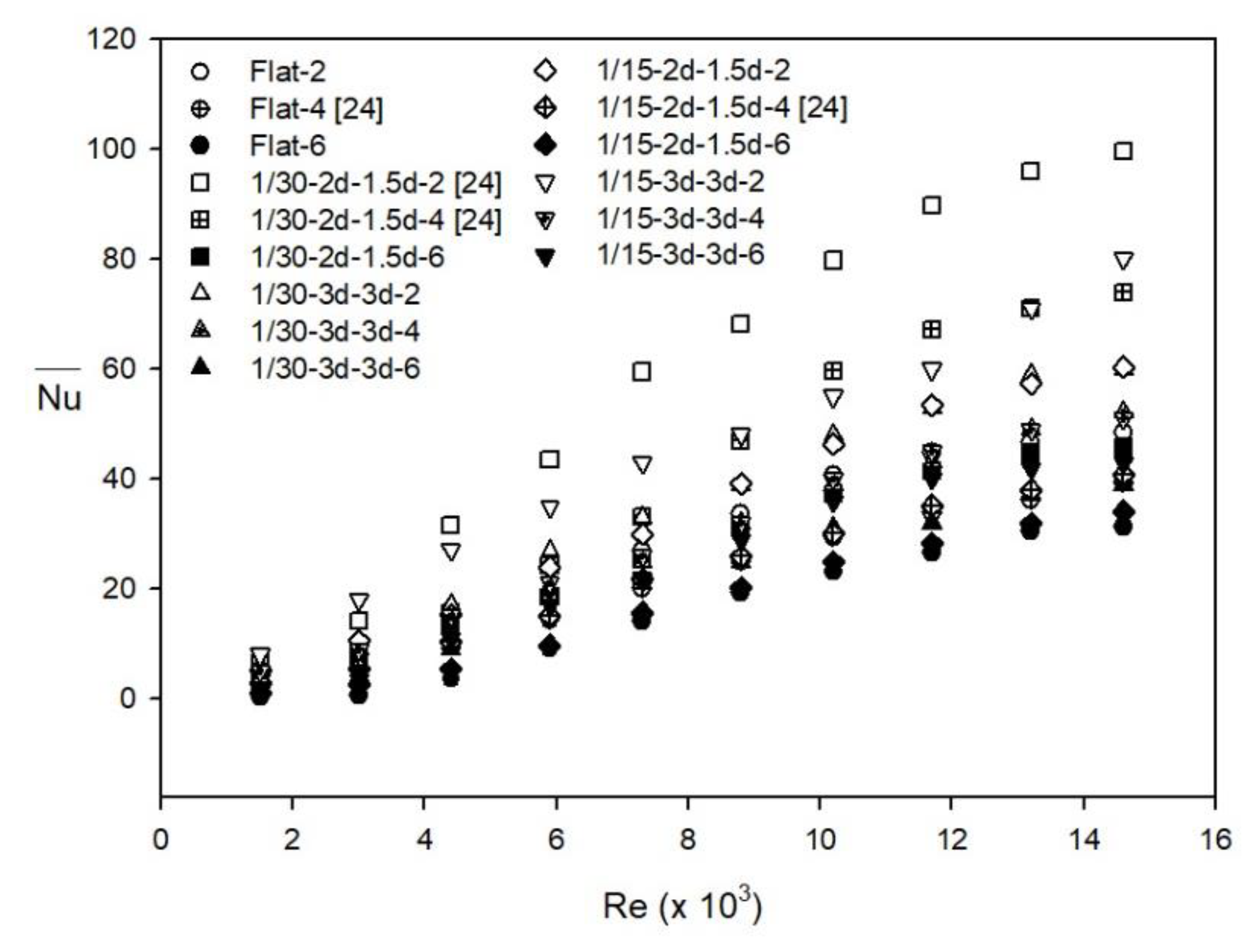
The average Nusselt number () was calculated from the experiment results and converted to the heat transfer rate. A higher resulted in a higher heat transfer rate. The results of the flat plate and the dimple plate (at dimple diameters of (d) = 1 and 2 cm) were compared alongside the Reynolds numbers, as shown in Figure 5. The results show that increases as the Reynolds number increases. The of the dimpled plate was higher than that of the flat plate for all Reynolds numbers in the range. At Re = 14,600, Er = 2 d, Eθ = 1.5 d and B = 2, the Nusselt numbers of the test plate at d = 1 cm was 100 and d = 2 cm was 60. The at d = 1 cm was about 170% higher than at d = 2 cm.
From Figure 6, it can be seen that the local Nusselt number () distributions on the test plate are the highest around the center of the plate and they tend to decrease with increasing distance from the center of the test plate (Er). The local Nusselt numbers of dimpled surfaces were also higher than those of the flat plate, because the dimpled shape resulted in the vortex, an increase in turbulent intensity and a larger heat transfer area.
5.2. Effect on the Distance Between Test Plate and Jet (B)
There were three distances between the nozzle jet and test plate (B), which were 2 d, 4 d and 6 d. The results show that the shorter the distance between the nozzle jet and test plate, the higher the and , as shown in Figure 5 and Figure 6. values on the same test plate (d = 1 cm, Er = 2 d, Eθ = 1.5 d and Re = 14,600) were 100, 75 and 45 at B = 2 d, 4 d and 6 d, respectively.
In Figure 7, it can be seen that the local Nusselt number (Nu) of the shortest B (B = 2 d) is the highest. This is due to the fact that the shortest distance between the nozzle jet and test plate (B) caused the strongest impingement on the test plate and the highest turbulence intensity.
5.3. Effect of the Distance between Dimples (Er, Eθ)
There were two types of distance between dimples (Er, Eθ), which were Er = 2 d, Eθ = 1.5 d and Er = 3 d, Eθ = 3 d. In Figure 5 and Figure 6, at the same dimple diameter (d) and the same distance between nozzle jet and test plate (B), the results show that the at Er = 2 d, Eθ = 1.5 was higher than at Er = 3 d, Eθ = 3 d. It means that a lower Er and Eθ indicates a higher , which is similar to the trend seen for (see Figure 6).
5.4. Simulation of Impinging Jet on Dimple Surface
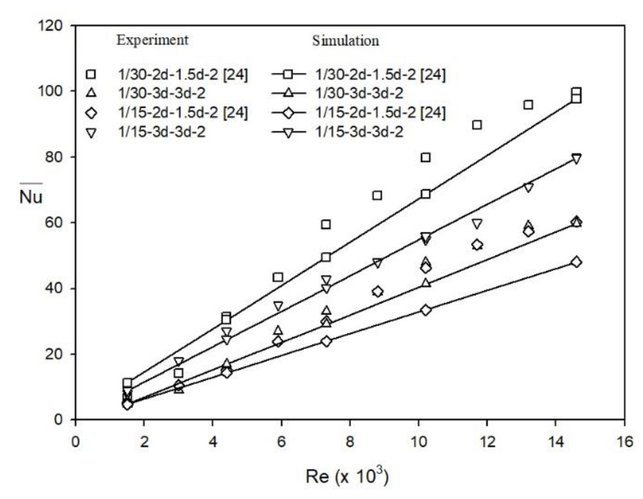
The flow behavior can be more clearly explained by the simulation data than by the experiment results, which allows us obtain highly efficient research results. Moreover, the data that cannot be measured in the experiment can be obtained from a simulation. In this work, the pressure drop on the test plate was very low and did not really differ in each experiment, which made it difficult to interpret the data. Therefore, the simulation was used to analyze the results. However, the precision of the simulation result was the most important factor. In this work, the comparisons between the experimental and simulation work are shown in Figure 7. It is worth noting that the numerical results are in good agreement with measurements. The discrepancies in the results were less than ±10% for all 15 case studies. The pressure drop was the important piece of data and it was converted to friction factor (f). The friction factor represents how easy or hard it is for the fluid to flow through the equipment. The equipment that uses high power to move the fluid will present with a high f, which shows the lower thermal enhancement factor (TEF). The TEF represents the total heat transfer capacity and can be calculated from Nu and f. A high TEF will be observed in test plates with a high heat transfer rate.
The friction factor ratios (f/f0) of the dimpled surface and flat plate are shown in Figure 8. The results show that f/f0 increases as the Re increases. At the same Re, a higher f/f0 will be obtained at a shorter distance between the nozzle jet and test plate (B), and a higher dimple distance (Er and Eθ). For example, the highest f/f0 value of 7 (TEF = 0.9) was observed in the test section plate at d = 2 cm, B = 1 d, Er= 3 d, Eθ = 3 d and Re = 14,600. On the other hand, the highest TEF value of 5.5 (f/f0 = 4) was observed at d = 1 cm, B = 2 d, Er= 2 d, Eθ = 1.5 d and Re = 1500 (see Figure 9).
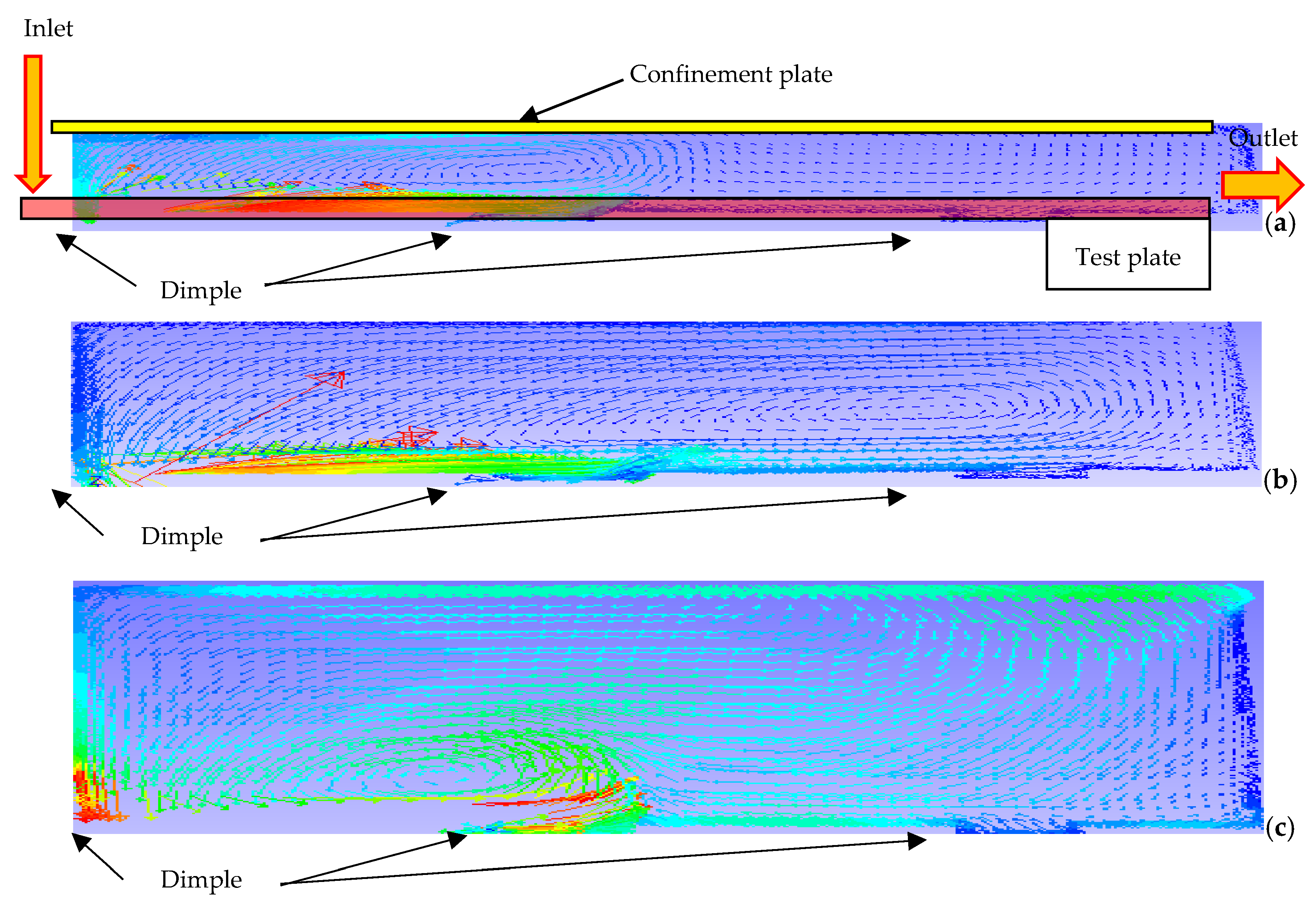
The air flow characteristics and heat transfer results can be analyzed by using a simulation technique. Figure 10 shows the 15 kinds of air flow, impinging on the test-section plate. The highest velocity air flow (long arrow sign) presented itself in the distance between the nozzle jet and test-section plate. The vortex then occurred near the center of test plate. The shorter B indicates turbulent fluid flow. The vortex and turbulent flow occur more often on the dimpled plate than the flat plate, which leads to better heat transfer. On a plate with a bigger dimple diameter (2 cm), the small vortex is observed above the dimple area at the outlet of the test plate. The cold air cannot be exchanged with the hot air because the vortex flow blocks the air flow. A small dimple diameter (1 cm) results in a higher TEF.
The air flow characteristics which resulted from the different Re values in five of the cases studied (Re = 1500, 4400, 7300, 10,200 and 14,600), at d = 1 cm, B = 2 d, Er= 2 d, and Eθ = 1.5 d, are shown in Figure 11. The results show that the vortex flow increases as Re increases, resulting in a higher TEF.
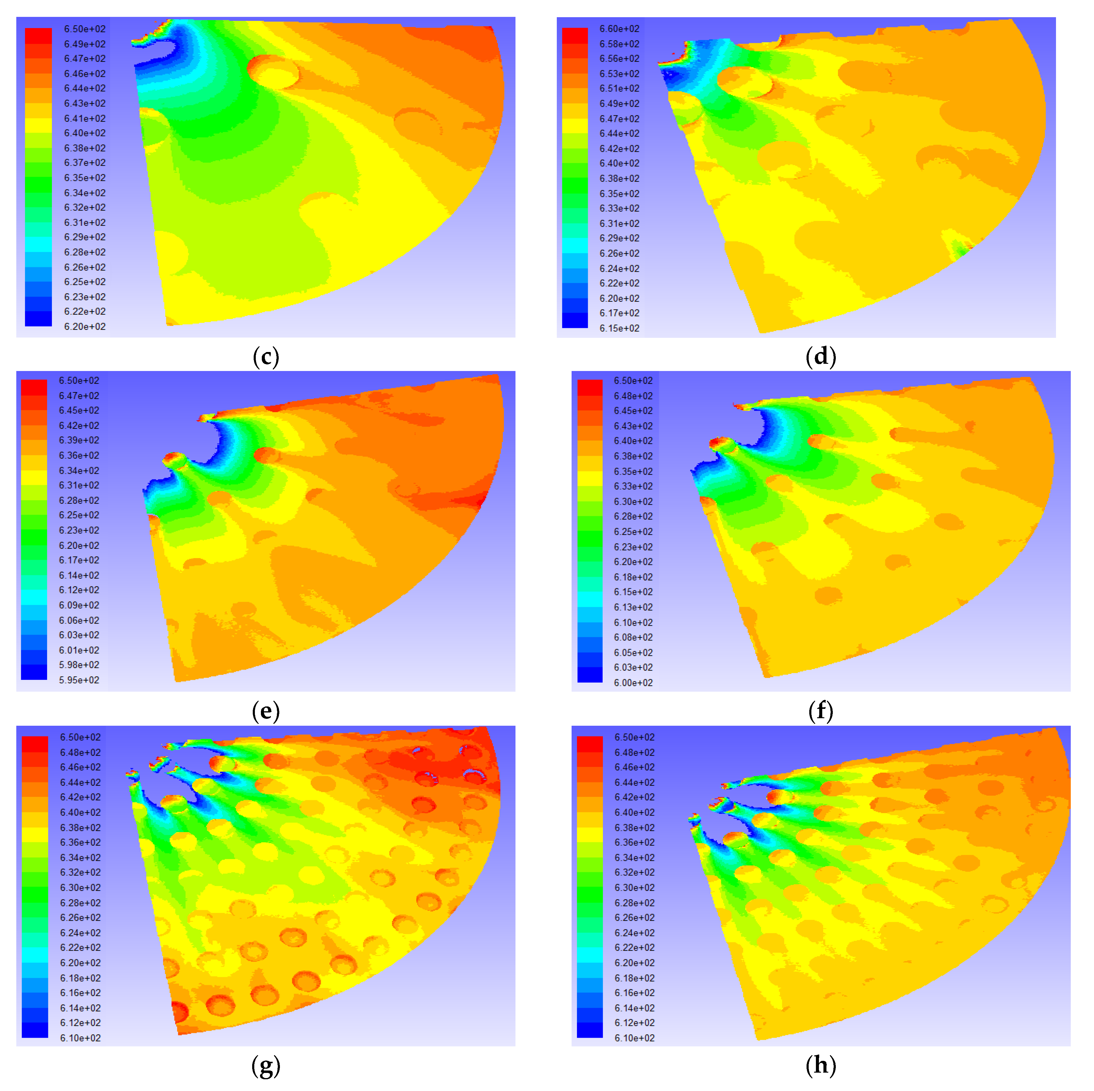
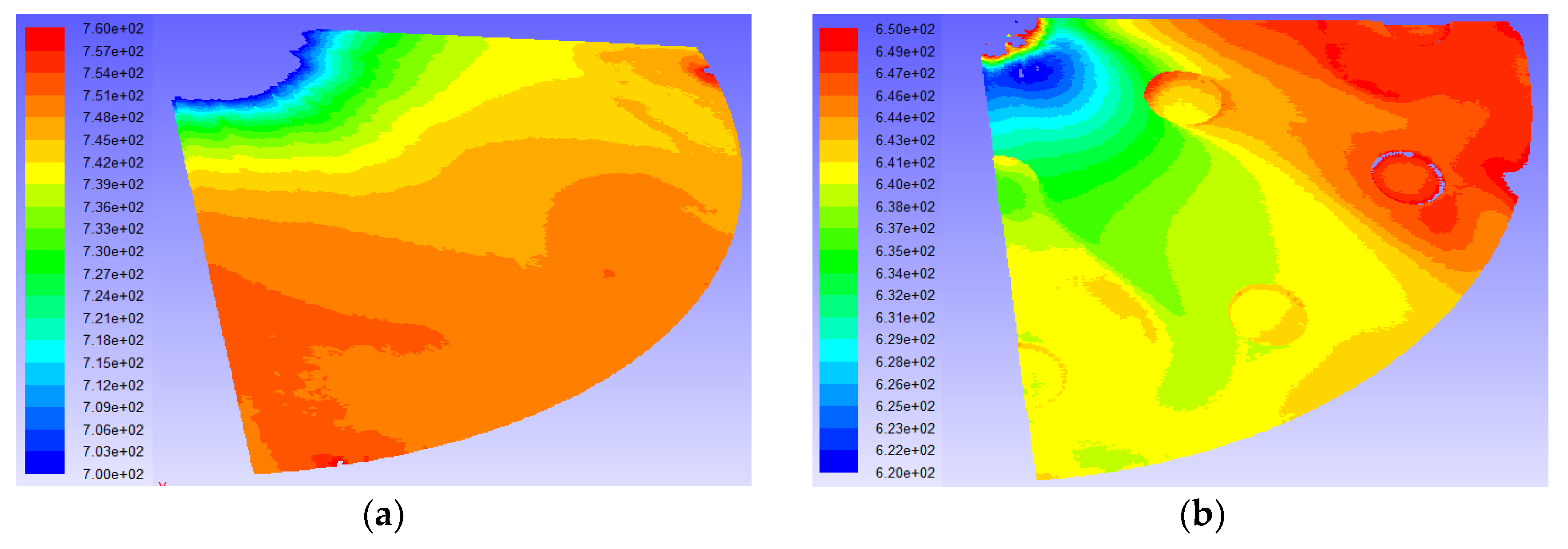
The temperature contours on the test section plate are shown in Figure 12. A higher TEF occurs at a lower temperature because of the heat transfer of the air from the wall to the air. The lower temperature of the test section results in a higher TEF. At d = 1 cm, B = 2 d, Er = 2 d, Eθ = 1.5 d, a higher TEF is observed at the lowest temperature contour.
6. Conclusions
Actual experiments were carried out and the results utilized as part of the analysis in the simulation part. In the simulation, the heat transfer behavior and friction factor value on the test plate were investigated for the thermal enhancement factor (TEF). TEF can be explained by the heat transfer efficiency of an impinging jet on the test plate. The optimum conditions in terms of the fluid pump power and heat transfer value could be obtained.
From the experiment and simulation results, one can conclude that the cylindrical dimpled surface enhances the TEF. The highest TEF (= 5.5) was found for the configuration with a dimple diameter of d = 1 cm, a radial dimple distance of Er = 2 d, a circumferential dimple distance of Eθ = 1.5 d, a distance between test plate and jet of B = 2, and Reynolds number of Re = 1500. The TEF which was obtained in this work was higher than that obtained in other research, which was about 4.0. This is because the friction factor ratio in this work (f/f0) was very low, even though the was not different from the in other work. The most suitable test plate conditions which could be used to obtain a high TEF are d = 1 cm, B = 2 d, Er = 2 d and Eθ = 1.5 d for Re=1500–14,600.
Author Contributions
For research articles with several authors, a short paragraph specifying their individual contributions must be provided. The following statements should be used “conceptualization, supervision, and methodology, Parkpoom Sriromreun; formal analysis, and writing—review and editing, Paranee Sriromreun”.
Funding
This research was funded by the Research Grants of Faculty of Engineering, Srinakharinwirot University and The Strategic Wisdom and Research Institute, Srinakharinwirot University.
Acknowledgments
The funding of this research work is supported by the Research Grants of Faculty of Engineering, Srinakharinwirot University and The Strategic Wisdom and Research Institute, Srinakharinwirot University.
Conflicts of Interest
The authors declare no conflict of interest.
References
- Ries, F.; Li, Y.; Klingenberg, D.; Nishad, K.; Janicka, J.; Sadiki, A. Near-Wall Thermal Processes in an Inclined Impinging Jet: Analysis of Heat Transport and Entropy Generation Mechanisms. Energies 2018, 11, 1354. [Google Scholar] [CrossRef]
- Ries, F.; Li, Y.; Nishad, K.; Janicka, J.; Sadiki, A. Entropy Generation Analysis and Thermodynamic Optimization of Jet Impingement Cooling Using Large Eddy Simulation. Entropy 2019, 21, 129. [Google Scholar] [CrossRef]
- Meola, C.; de Luca, L.; Carlomagno, G.M. Influence of shear layer dynamics on impingement heat transfer. Exp. Therm. Fluid Sci. 1996, 13, 29–37. [Google Scholar] [CrossRef]
- Guerra, D.R.S.; Su, J.; Silva Freire, A.P. The near wall behavior of an impinging jet. Int. J. Heat Mass Transf. 2005, 48, 2829–2840. [Google Scholar] [CrossRef]
- Chaudhari, M.; Puranik, B.; Agrawal, A. Heat transfer characteristics of synthetic jet impingement cooling. Int. J. Heat Mass Transf. 2010, 53, 1057–1069. [Google Scholar] [CrossRef]
- Draksler, M.; Končar, B. Analysis of heat transfer and flow characteristics in turbulent impinging jet. Nucl. Eng. Des. 2011, 241, 1248–1254. [Google Scholar] [CrossRef]
- Nanan, K.; Wongcharee, K.; Nuntadusit, C.; Eiamsa-ard, S. Forced convective heat transfer by swirling impinging jets issuing from nozzles equipped with twisted tapes. Int. Commun. Heat Mass Transf. 2012, 39, 844–852. [Google Scholar] [CrossRef]
- Nuntadusit, C.; Wae-hayee, M.; Bunyajitradulya, A.; Eiamsa-ard, S. Heat transfer enhancement by multiple swirling impinging jets with twisted-tape swirl generators. Int. Commun. Heat Mass Transf. 2012, 39, 102–107. [Google Scholar] [CrossRef]
- Qiang, Y.; Wei, L.; Luo, X.; Jian, H.; Wang, W.; Li, F. Heat Transfer and Flow Structures of Laminar Confined Slot Impingement Jet with Power-Law Non-Newtonian Fluid. Entropy 2018, 20, 800. [Google Scholar] [CrossRef]
- Tong, A.Y. On the impingement heat transfer of an oblique free surface plane jet. Int. J. Heat Mass Transf. 2003, 46, 2077–2085. [Google Scholar] [CrossRef]
- Goodro, M.; Park, J.; Ligrani, P.; Fox, M.; Moon, H.-K. Effects of hole spacing on spatially-resolved jet array impingement heat transfer. Int. J. Heat Mass Transf. 2008, 51, 6243–6253. [Google Scholar] [CrossRef]
- Pakhomov, M.A.; Terekhov, V.I. Enhancement of an impingement heat transfer between turbulent mist jet and flat surface. Int. J. Heat Mass Transf. 2010, 53, 3156–3165. [Google Scholar] [CrossRef]
- Ekkad, S.V.; Kontrovitz, D. Jet impingement heat transfer on dimpled target surfaces. Int. J. Heat Fluid Flow 2002, 23, 22–28. [Google Scholar] [CrossRef]
- Lienhart, H.; Breuer, M.; Köksoy, C. Drag reduction by dimples? A complementary experimental/numerical investigation. Int. J. Heat Fluid Flow 2008, 29, 783–791. [Google Scholar] [CrossRef]
- Kanokjaruvijit, K.; Martinez-Botas, R.F. Heat transfer correlations of perpendicularly impinging jets on a hemispherical-dimpled surface. Int. J. Heat Mass Transf. 2010, 53, 3045–3056. [Google Scholar] [CrossRef]
- Xing, Y.; Weigand, B. Experimental investigation of impingement heat transfer on a flat and dimpled plate with different crossflow schemes. Int. J. Heat Mass Transf. 2010, 53, 3874–3886. [Google Scholar] [CrossRef]
- Won, Y.; Wang, E.N.; Goodson, K.E.; Kenny, T.W. 3-D visualization of flow in microscale jet impingement systems. Int. J. Therm. Sci. 2011, 50, 325–331. [Google Scholar] [CrossRef]
- Kwon, H.G.; Hwang, S.D.; Cho, H.H. Measurement of local heat/mass transfer coefficients on a dimple using naphthalene sublimation. Int. J. Heat Mass Transf. 2011, 54, 1071–1080. [Google Scholar] [CrossRef]
- Turnow, J.; Kornev, N.; Zhdanov, V.; Hassel, E. Flow structures and heat transfer on dimples in a staggered arrangement. Int. J. Heat Fluid Flow 2012, 35, 168–175. [Google Scholar] [CrossRef]
- De Bonis, M.V.; Ruocco, G. An experimental study of the local evolution of moist substrates under jet impingement drying. Int. J. Therm. Sci. 2011, 50, 81–87. [Google Scholar] [CrossRef]
- Parida, P.R.; Ekkad, S.V.; Ngo, K. Experimental and numerical investigation of confined oblique impingement configurations for high heat flux applications. Int. J. Therm. Sci. 2011, 50, 1037–1050. [Google Scholar] [CrossRef]
- Na-pompet, K.; Boonsupthip, W. Effect of a narrow channel on heat transfer enhancement of a slot-jet impingement system. J. Food Eng. 2011, 103, 366–376. [Google Scholar] [CrossRef]
- Alenezi, A.; Almutairi, A.; Alhajeri, H.; Addali, A.; Gamil, A. Flow Structure and Heat Transfer of Jet Impingement on a Rib-Roughened Flat Plate. Energies 2018, 11, 1550. [Google Scholar] [CrossRef]
- Sriromreun, P.K.; Sriromreun, P.N. Experimental and Numerical Studies of Heat Transfer Characteristics for Impinging Jet on Dimple Surfaces. Chem. Eng. Trans. 2018, 70, 1273–1278. [Google Scholar] [CrossRef]
- ANSI/ASME. Test Uncertainty. Available online: http://gost-snip.su/download/asme_ptc_19_1, 2005_test_uncertainty (accessed on 28 February 2019).
- Patankar, S.V. Numerical Heat Transfer and Fluid Flow; McGraw-Hill: New York, NY, USA, 1980. [Google Scholar]
- Versteeg, H.K.; Malalasekera, W. An Introductionto ComputationalFluid Dynamics, The Finite Volume Method, 2nd ed.; PEARSON Prentice Hall: London, UK, 2007. [Google Scholar]
- Incropera, F.P.; Dewitt, D.B. Introduction to Heat Transfer, 5th ed.; John Wiley and Sons, Inc.: Hoboken, NJ, USA, 2007. [Google Scholar]
Figure 1.
(a) Schematic diagram of experimental apparatus, (b) Details of the impingement dimples on the surface at Er = 2 d and Eθ = 1.5 d, (c) at Er = 3 d and Eθ = 3 d, (d) The depth of the dimples.
Figure 1.
(a) Schematic diagram of experimental apparatus, (b) Details of the impingement dimples on the surface at Er = 2 d and Eθ = 1.5 d, (c) at Er = 3 d and Eθ = 3 d, (d) The depth of the dimples.

Figure 2.
Test section.

Figure 3.
Channel geometry and Computational domain of flow.

Figure 4.
Temperature on the test plate, air inlet and outlet of Re at 10,200 (experiment).

Figure 5.
Variation of with Re for flat plate and dimpled plate (experiment).

Figure 6.
Nusselt number distribution at an Re of 10,200 for the flat plate and dimpled plate (experiment).
Figure 6.
Nusselt number distribution at an Re of 10,200 for the flat plate and dimpled plate (experiment).

Figure 7.
Variation of with Re for the flat plate and dimpled plate (experiment and simulation).

Figure 8.
Variation of f/f0 with Re of the dimpled plate (simulation).

Figure 9.
Variation of TEF with Re for the dimpled plate (simulation).

Figure 10.
Streamlines at Re = 14,600: (d/D-Er-Eθ-B) (a) 1/15-3-3-2, (b) 1/15-3-3-4, (c) 1/15-3-3-6, (d) 1/30-3-3-2, (e) 1/30-3-3-4, (f) 1/30-3-3-6, (g) 1/30-2-1.5-2, (h) 1/30-2-1.5-4 [24] and (i) 1/30-2-1.5-6.
Figure 10.
Streamlines at Re = 14,600: (d/D-Er-Eθ-B) (a) 1/15-3-3-2, (b) 1/15-3-3-4, (c) 1/15-3-3-6, (d) 1/30-3-3-2, (e) 1/30-3-3-4, (f) 1/30-3-3-6, (g) 1/30-2-1.5-2, (h) 1/30-2-1.5-4 [24] and (i) 1/30-2-1.5-6.


Figure 11.
Streamlines with d = Dj and B = 2 Dj at (a) Re = 1500, (b) Re = 4400, (c) Re = 7300, (d) Re = 10,200 and (e) Re = 14,600 [24].
Figure 11.
Streamlines with d = Dj and B = 2 Dj at (a) Re = 1500, (b) Re = 4400, (c) Re = 7300, (d) Re = 10,200 and (e) Re = 14,600 [24].

Figure 12.
Temperature contours (K) at Re = 14,600: (d/D-Er-Eθ-B) (a) F-2, (b) 1/15-3-3-2, (c) 1/15-3-3-4, (d) 1/15-2-1.5-4 [24], (e) 1/30-3-3-2, (f) 1/30-3-3-4, (g) 1/30-2-1.5-2 [24], and (h) 1/30-2-1.5-4 [24].


Table 1.
The detail of the geometry of the impingement plate with dimples and tested conditions.
| Working Fluid | Air |
|---|---|
| Reynolds number (Re) | 1500 to 14,600 |
| Jet diameter (Dj) | 1 cm |
| Plate diameter (D) | 30 cm |
| Depth of dimple | 0.5 cm |
| Dimple diameter (d) | Dj and 2 Dj |
| Dimple distance in the radius (Er) | 2 d, 3 d |
| Dimple distance in the circumference (Eθ) | 1.5 d, 3 d |
| The distance between test plates and jet (B) | 2 Dj, 4 Dj and 6 Dj |
Table 2.
The 15 case studies in detail.
| Dimple Diameter/Plate Diameter (d/D) | Dimple Distance in the Radius (Er) | Dimple Distance in the Circumference (Eθ) | The Distance between Test Plates and Jet (B) | Case Study Name (d/D-Er-Eθ-B) |
|---|---|---|---|---|
| Flat | - | - | 2 | Flat-2 |
| Flat | - | - | 4 | Flat-4 [24] |
| Flat | - | - | 6 | Flat-6 |
| 1/5 | 3 d | 3 d | 2 | 1/15-3 d-3 d-2 |
| 1/5 | 3 d | 3 d | 4 | 1/15-3 d-3 d-4 |
| 1/5 | 3 d | 3 d | 6 | 1/15-3 d-3 d-6 |
| 1/5 | 2 d | 1.5 d | 2 | 1/15-2 d-1.5 d-2 |
| 1/5 | 2 d | 1.5 d | 4 | 1/15-2 d-1.5 d-4 [24] |
| 1/5 | 2 d | 1.5 d | 6 | 1/15-2 d-1.5 d-6 |
| 1/30 | 3 d | 3 d | 2 | 1/30-3 d-3 d-2 |
| 1/30 | 3 d | 3 d | 4 | 1/30-3 d-3 d-4 |
| 1/30 | 3 d | 3 d | 6 | 1/30-3 d-3 d-6 |
| 1/30 | 2 d | 1.5 d | 2 | 1/30-2 d-1.5 d-2 [24] |
| 1/30 | 2 d | 1.5 d | 4 | 1/30-2 d-1.5 d-4 [24] |
| 1/30 | 2 d | 1.5 d | 6 | 1/30-2 d-1.5 d-6 |
© 2019 by the authors. Licensee MDPI, Basel, Switzerland. This article is an open access article distributed under the terms and conditions of the Creative Commons Attribution (CC BY) license (http://creativecommons.org/licenses/by/4.0/).
Share and Cite
MDPI and ACS Style
Sriromreun, P.; Sriromreun, P. A Numerical and Experimental Investigation of Dimple Effects on Heat Transfer Enhancement with Impinging Jets. Energies 2019, 12, 813. https://doi.org/10.3390/en12050813
AMA Style
Sriromreun P, Sriromreun P. A Numerical and Experimental Investigation of Dimple Effects on Heat Transfer Enhancement with Impinging Jets. Energies. 2019; 12(5):813. https://doi.org/10.3390/en12050813
Chicago/Turabian StyleSriromreun, Parkpoom, and Paranee Sriromreun. 2019. "A Numerical and Experimental Investigation of Dimple Effects on Heat Transfer Enhancement with Impinging Jets" Energies 12, no. 5: 813. https://doi.org/10.3390/en12050813
Note that from the first issue of 2016, this journal uses article numbers instead of page numbers. See further details here.