The Influence of Permanent Magnet Material Properties on Generator Rotor Design


Division of Electricity, Uppsala University, SE-751 05 Uppsala, Sweden
*
Author to whom correspondence should be addressed.
Energies 2019, 12(7), 1314; https://doi.org/10.3390/en12071314
Submission received: 28 February 2019
/
Revised: 24 March 2019
/
Accepted: 29 March 2019
/
Published: 5 April 2019
(This article belongs to the Special Issue Permanent Magnet Synchronous Machines)
Abstract
:Due to the price and supply insecurities for rare earth metal-based permanent magnet (PM) materials, a search for new PM materials is ongoing. The properties of a new PM material are not known yet, but a span of likely parameters can be studied. This paper presents an investigation on how the remanence and recoil permeability of a PM material affect its usefulness in a low speed, multi-pole, and PM synchronous generator. Demagnetisation is also considered. The investigation is carried out by constrained optimisation of three different rotor topologies for maximum torque production for different PM material parameters and a fixed PM maximum energy. The rotor topologies used are surface mounted PM rotor, spoke type PM rotor and an interior PM rotor with radially magnetised PMs. The three different rotor topologies have their best performance for different kinds of materials. The spoke type PM rotor is the best at utilising low remanence materials as long as they are sufficiently resistant to demagnetisation. The surface mounted PM rotor works best with very demagnetisation resistant PM materials with a high remanence, while the radial interior PM rotor is preferable for high remanence materials with low demagnetisation resistance.
1. Introduction
Low speed, high torque synchronous machines are primarily used in wind power, as direct driven generators. They can employ permanent magnet (PM) excitation to reduce complexity and increase efficiency. The most common group of PM materials used are based on neodymium-iron-boron (Nd-Fe-B) systems, which have very good performance [1]. In the last decade, there has been a volatility in price of these kinds of PMs, which has sparked the search for more economically stable alternatives [2]. One option is to use ferrites, but this requires a more mechanically complex and heavier rotor, such as a flux concentrating spoke type rotor [3,4,5], than the relatively simple surface mounted PM rotor that can be used with Nd-Fe-B [6,7]. Another approach is the development of new PM materials [8]. Suitable rare earth metal–free systems for use as PM materials are currently being investigated. Ref. [9] presents a theoretical study of FeCo alloys. Ref. [10] is a theoretical study of magnetic properties of the alloys FeNi, CoNi, MnAl, and MnGa. Ref. [11] presents measurements for MnAl. These novel materials are not likely to outperform the Nd-Fe-B and Samarium-Cobalt (Sm-Co) PM materials but could provide a cost efficient rare-earth metal free alternative. In addition, research is performed on recycled rare-earth magnets, expected to have properties in between ferrites and commercial Nd-Fe-B [12]. It can be of interest to investigate how to best utilise possible new or recycled materials, even though the novel magnets are not developed and commercialised yet.
In this study, the suitability of different PM material properties for use with different PM synchronous generator rotor topologies is investigated. Different rotor topologies subject the PM to different permeance, which results in different load lines. In [1], it is discussed how different load lines interact with the demagnetisation magnetic flux density curve. Different rotor topologies have been studied previously. In [13], three topologies, similar to those studied here, are compared for use in 4-pole traction motors for trains. Similar topologies are compared for use as an aircraft starter-generator in [14]. Five different topologies, not including the spoke-type rotor, are compared in [15]. Ref. [16] also compares five different topologies, including the spoke-type rotor. Ref. [17] compares machines with Nd-Fe-B, Sm-Co and alnico for surface mounted 4-pole machines. Ref. [18] compares three machine configurations for interior v-shaped magnets for two different materials: the novel material NdFeN and a conventional Nd-Fe-B magnet. A spoke-type rotor with ferrites is compared to a rotor with surface mounted Nd-Fe-B magnets for a wind power generator in [19,20]. A comparison of demagnetization risk for the same generator types is presented in [21].
The aim of this paper is to study how the magnetic properties of PM materials affect the machine design in low-speed radial flux PM generators. To our knowledge, there has not been any previous study combining material properties with rotor design and rotor topology choice. The results from this study could give hints on which property to improve when developing new PM materials as well as on the suitability of a material with certain magnetic properties for different generator topologies.
2. Scope and Limitations
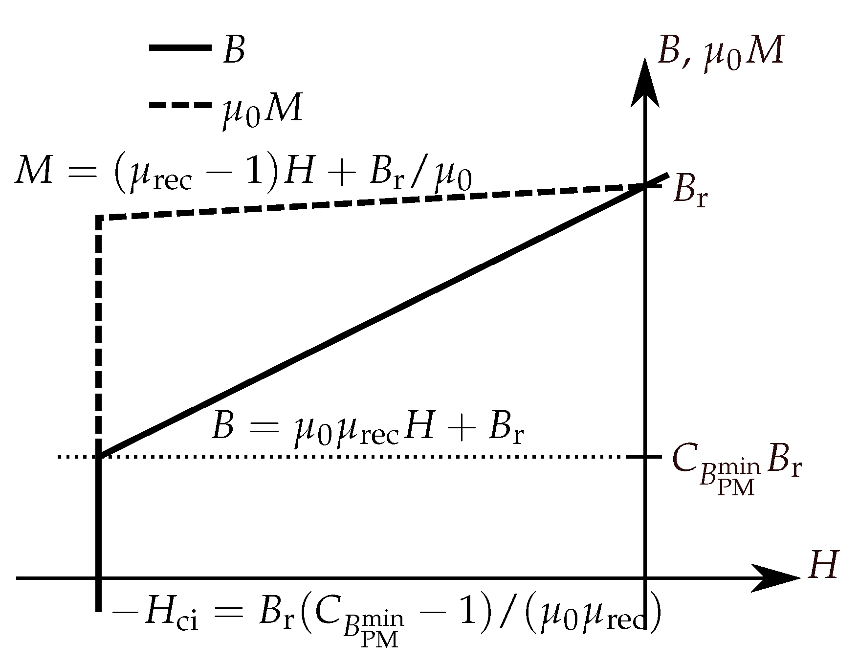
The PM material is described by three parameters and three different PM rotor topologies are compared. The PM material parameters used are the remanent flux density , the recoil permeability , and a demagnetization parameter denoted . The second quadrant demagnetisation curve given by the parameters is shown in Figure 1. The demagnetisation parameter gives a minimum value of magnetic flux density along the magnetisation allowed in the PM as fraction . Considering demagnetisation is important since the different topologies can be expected to provide different levels of protection against demagnetisation [21].
The figure of merit used in comparison is torque per unit machine length and pole pair, with a fixed electrical loading of the stator and a fixed amount of magnetic energy in the rotor. The machine used in the study is a generator with 40 poles and a stator inner diameter of slightly over one meter; no length is set as all calculations are done per unit length. The generator would be suitable for use in a small scale direct drive wind turbine. A direct drive generator for a wind turbine is normally not operated at high loading at normal operation, so no saturation or flux weakening operation is expected. Typical torque curves for this type of generator can be seen in [19].
Magnetic properties for PMs are normally defined with temperate coefficients explaining how they change with temperature. The coefficients vary both in size and in sign and it is therefore not possible to include temperature variations of magnetic properties in this study. However, as the generator is a small scale, large-diameter generator which is considered sufficiently cooled (or heated if needed), it can be considered to have a rather small allowed temperature span. The material parameters in the results should be interpreted as those valid for the operating temperature.
The stator is made as generic as possible, without any specific winding scheme and will not be subject to optimisation. The end windings are not included in the model and all calculations are performed per unit of machine length, i.e., only two dimensions are considered. It is also kept as geometrically simple as possible to make meshing for the simulation easier. The rotor topologies are optimised only with respect to the rectangular shape of the PM, with the volume of PM material kept fixed for each point in the parameter space. The amount of iron is not part of the objective function but is changed as necessary to accommodate the PM. Structural integrity is not considered and it is assumed that the PM material can be shaped into blocks of the required sizes.
3. Method
The three different PM rotor topologies are optimised for torque production, for multiple points in a parameter space of PM material properties, and are then compared. The topologies compared are surface mounted PM rotor, spoke PM rotor and capped PM rotor, all of which will be presented in detail below. The stator is kept the same both geometrically and electrically. Each PM material point is defined by the values of the PM material parameters , , and . The values of are varied between T and T, in steps of T. The lower bound is chosen because a material with lower is unlikely to be useful in an electrical machine, and the upper bound is chosen slightly above what is commercially available. The values of are varied between 1 and 2, in eight logarithmically distributed steps. The lower bound is given by fundamental physics and the upper is judged to be high enough for the investigated space to contain most useful materials. Approximate PM material parameter values of commercially available PM material types are listed in Table 1 for reference.
The amount of PM material used in a given PM material point is chosen to give the same PM maximum energy, in order to allow fair comparison between materials. The PM maximum energy, assuming a linear second quadrant demagnetisation curve, is calculated as
where is the maximum energy product of the PM material, is the cross section area of the PM and l the length of the machine, set to unity. The resulting for varies from m2 to m2. The is chosen to match that of a surface mounted PM covering of the pole pitch, with a height of twice the air gap length, , and (assuming ). This can be considered a typical generator design for a rotor with Nd-Fe-B magnets and thereby gives a representative -value.
A parameterised geometry is created for each of the rotor topologies and the stator. The geometry only represents a two-dimensional cross section, as common when simulating radial flux machines, to save computation time. This can be done since, for the most of the machine length, there is very little change of geometry in the axial direction and since end effects are expected to be small as long as the axial length is of sufficient length. The equations governing magnetostatics, in vector potential formulation, are combined with constitutive equations, boundary conditions and source terms, and solved using the finite element (FE) method on the parametrised geometry. The torque is calculated from the obtained field by integrating the Maxwell stress in the air gap. Constrained optimisation is done of the ratio between height (along magnetisation) and width of the PM, on a closed interval bounded by the requirement to keep the geometry consistent.
3.1. Geometries and Rotor Topologies
Both the stator geometry and all of the rotor geometries have their sizes defined in terms of the pole pitch, , number of pole pairs, P, PM height, , and PM width, . How the remaining geometrical parameters depend on these are listed in Table 2. The parameters are chosen to give a reasonable generator geometry for a small scale direct drive wind turbine. The choice of air gap length in a PM generator is mainly made from mechanical considerations. In literature, it is given that, for large machines, the air gap length needs to be due to manufacturing tolerances [22], p. 306. To be on the safe side, an air gap length of is chosen.
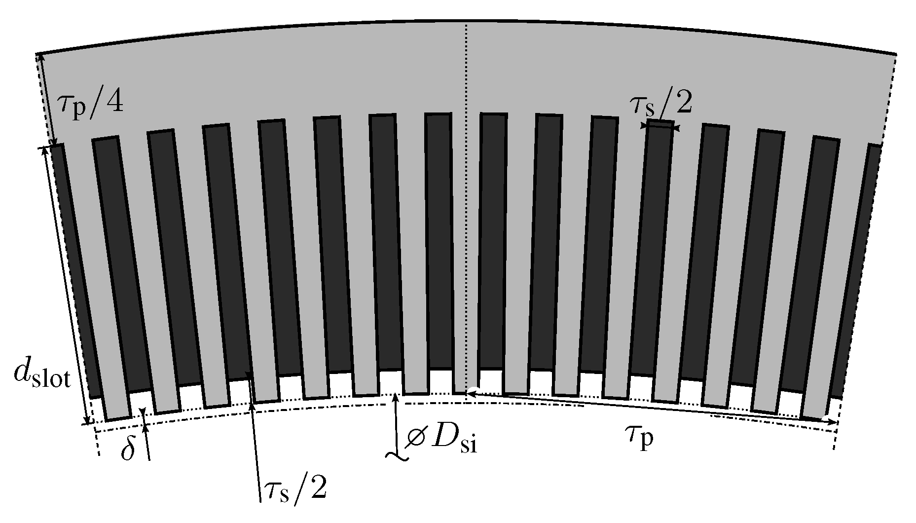
The stator geometry is simple, with a minimum of details in order to make it easier to mesh for the simulations—see Figure 2. The slots and teeth are of the same width at the inner periphery, and the slots are rectangular. A nonintegral number of slots per pole, , is chosen to reduce the cogging. The depth of the slots is chosen to give a typical current density in the conductor, while at the same time achieving a typical linear current density along the stator periphery, reasonable values are taken from [22], p. 298. The yoke is set large enough not to limit the magnetic flux, since the amount of iron used is not part of the optimisation.
The rotor topologies used are the surface mounted PM rotor, capped PM rotor, and spoke PM. While there are many other topologies to choose from and variations on each of them, see e.g., [13,14,15,16,18,19,23,24], the three chosen topologies are all relatively simple. All three topologies allow the PM to be represented as a rectangular block with a well defined height and width, along and across magnetisation, respectively. All rotors are designed to give the same air gap length, but the width of the pole face on the rotor is dependent on topology and PM size.
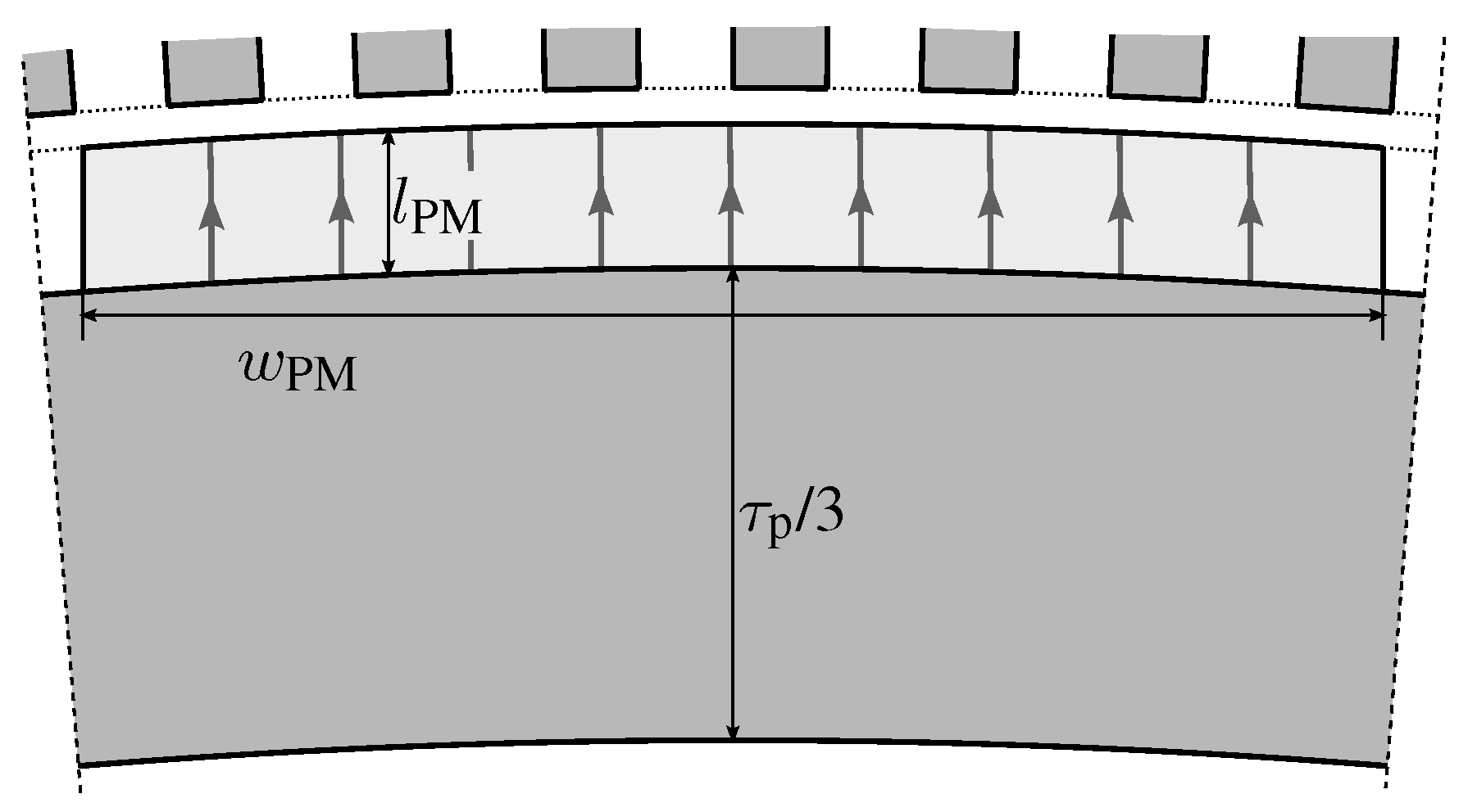
The surface mounted PM rotor consists of an iron back ring and the PMs, mounted directly on the ring. The geometry is shown in Figure 3. The PMs are curved to give a constant mechanical air gap length in front of the PMs. The curvature is the same on both curved sides, and the straight sides are parallel, such that the cross sectional area still is . Wedges holding the PMs are not included in the geometry to make it simple to mesh for the FE solver.
The capped PM rotor is an interior PM rotor with radially magnetised PMs see Figure 4. Its design is similar to the surface mounted rotor, with the addition of a magnetically soft pole shoe on top of the PM. This evens out the magnetic flux density in the PM and air gap slightly and helps protect the PM from demagnetisation. This kind of design is described as suitable for use with alnico PMs in [23], and a similar interior PM rotor design, with few poles and used for motor applications, is compared to a few other interior PM rotor topologies in [15]. Height of the pole shoe is fixed and not subject to optimisation. The width is changed to match the PM.
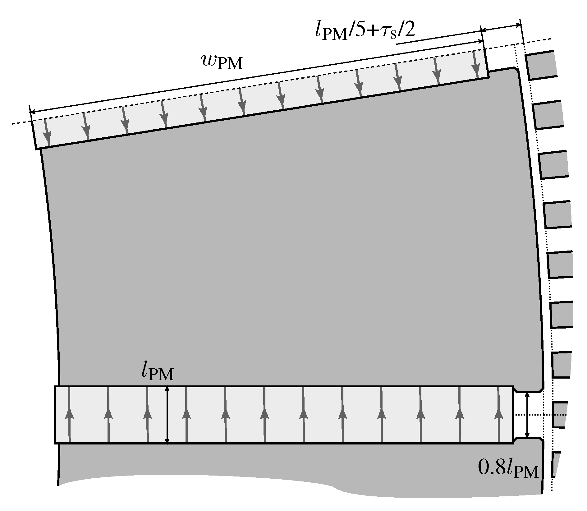
The spoke type PM rotor, also called tangential or circumferential interior PM rotor, consists of a ring formed by PMs of alternating, tangential magnetisation, separated by magnetically soft pole pieces that guide the magnetic flux into the air gap. The design of one rotor of this type is shown in [23] and is described as suitable for use with ferrite PMs. It is also used in [3] in a rotor with ferrite PMs intended to be interchangeable with a surface mounted rotor with Nd-Fe-B PMs. Pole pieces are sized to fill up the space between the PMs, starting at a slightly larger radius than the inward face of the PM and extending to the rotor periphery—see Figure 5. To avoid leakage flux between the poles at the rotor periphery, there is a slot in the rotor surface with the PM at the bottom.
3.2. Finite Element Modelling
The finite element software used is COMSOL Multiphysics® v. 5.2a (COMSOL AB, Stockholm, Sweden) together with the MATLAB® LiveLink™ package (MATLAB R2017a, Mathworks, Inc., Natick, MA, USA) to interface with the optimiser. The field equation solved is the one of magnetostatics, i.e., stationary simulations, with magnetic vector potential and all out of plane derivatives set to zero. This ensures that only the out of plane component of the vector potential needs to be calculated, since the in plane components are constant zero.
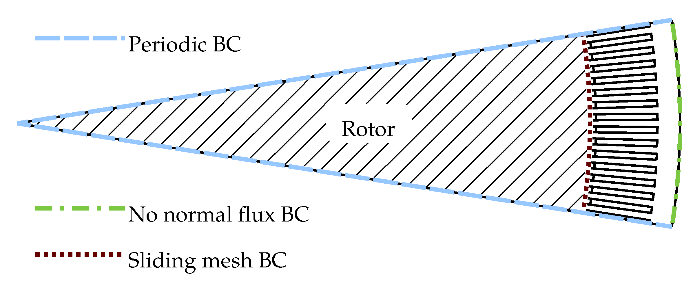
On the boundaries on the outside of the stator, a magnetic insulation boundary condition, i.e., zero normal component of the magnetic field, is used. For the boundaries between the pole pairs, periodic boundary conditions are used, in order to make use of the symmetry in the geometry and reduce the size of the computational domain. Between the stator and rotor mesh, a sliding boundary is used, to avoid re-meshing when rotating the rotor. The boundary conditions are shown in Figure 6.
The constitutive equations used to relate and in the materials are
where is the permeability of free space, for the air gap and stator slots. In the PMs, the material is represented by
and, for the soft iron parts, the equation is
where f is a monotonically increasing function representing the B-H curve of the iron. It is computed by table lookup with linear interpolation with data supplied as the generic “Soft Iron” material from the material library of COMSOL Multiphysics®. The B-H curve of the soft iron can be seen in Figure 7. The soft iron no conductivity and no hysteresis, i.e., iron losses are not included in the simulations.
The stator currents are introduced as regions of out-of-plane current density located in the slots. The distribution is sinusoidal, with an amplitude chosen to give a linear current density of (RMS) aligned to give resistive load. The current density is A/mm
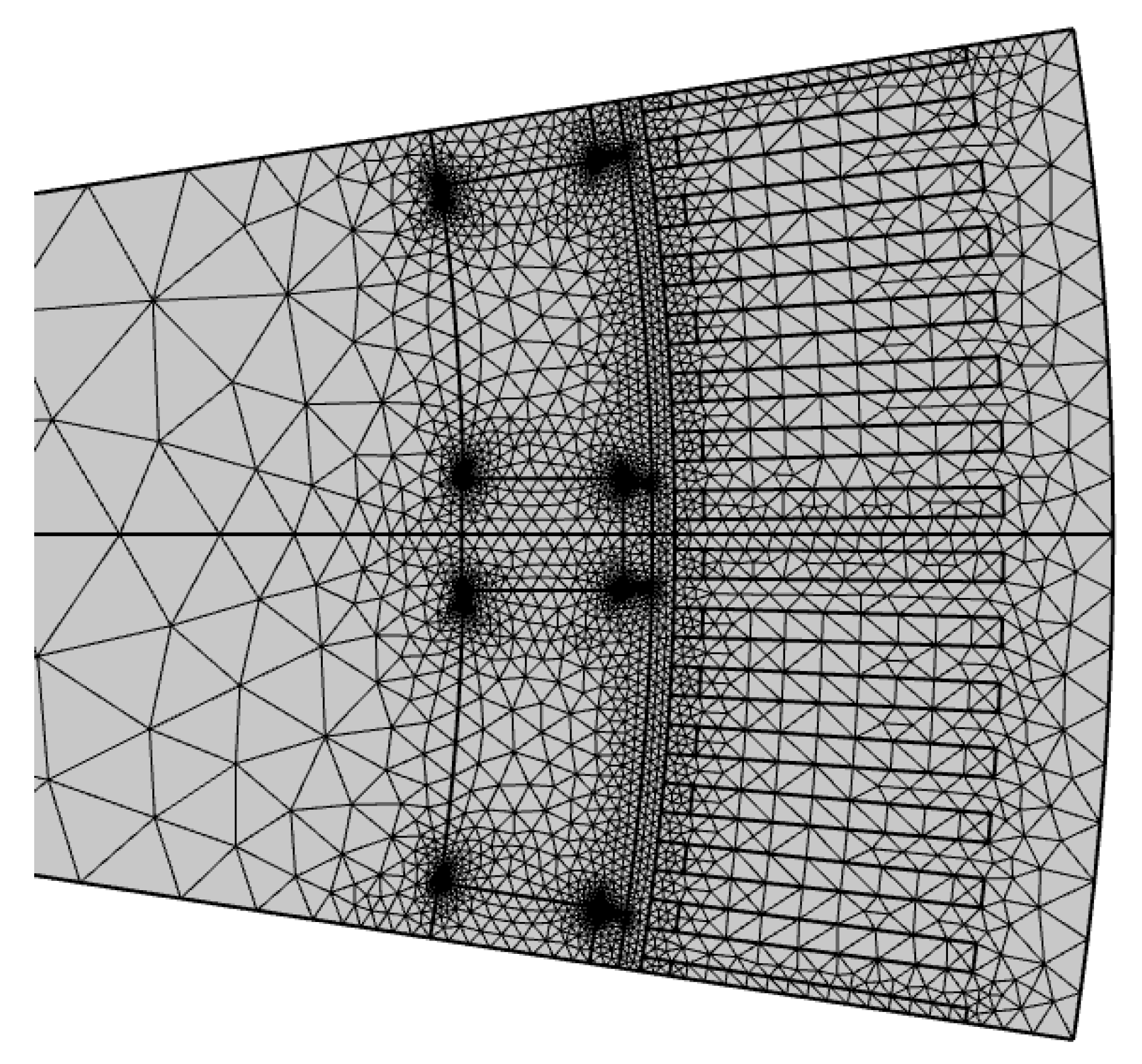
The meshing is done using the built in algorithms of the FE software, with the element size in the air gap set to be less than a third of the air gap length. This is done to ensure the solution in the air gap will be of sufficient quality to allow accurate calculation of the torque. The torque generated by the generator is calculated using the Arkkios method [25]. To reduce the influence of cogging on the results, the rotor is rotated one slot pitch, in ten steps, and the mean torque is calculated. The mesh for an example geometry is shown in Figure 8. Note that the mesh in the rotor will vary for each iteration, i.e., it varies both with PM shape and with rotor type.
3.3. Optimiser
The variable optimised is the shape of the PM given by its height along magnetisation, , and width, across magnetisation, , with the objective to find the maximum torque. The cross sectional area of the PM, , is kept constant. For the constrained optimisation, the MATLAB standard library function fminbnd is used. The function uses a combination of golden ratio search and successive parabolic interpolation to find the minimum of a unimodal function. An initial rough search is performed, to find a better interval for fminbnd to work on. The search starts by computing the torque in the lowest possible value of , storing the value, and then computing the torque for times the previous value of until either the maximum possible value of is reached, or the torque for the last is of smaller magnitude than that in previous steps.
3.4. Stability Analysis
To test the stability of the results against changes in the parameters, a stability analysis is performed by changing one parameter at the time. The parameters , , , and are tested at ±25%; additionally, is tested at and two times the default value. The number of pole pairs is tested at . The depth of the stator slots is tested at of their default value. The stability tests are run on a sparser grid of and with only four values each ( and ). All values of are still used.
3.5. Demagnetisation Prevention
To determine if the PM is risking demagnetisation, the component of the magnetic flux density parallel to the remanent magnetisation, , is compared to a threshold value , and the volume fraction of the PM where , denoted , is computed. The computation of is done for two cases, with no current in the stator windings, i.e., no load (NL), and for a symmetrical short circuit (SC). The short circuit case is a symmetrical short circuit at constant rotational speed. Two tolerances are used to determine if the demagnetisation is acceptable. The first is that at NL, , should be less than . The second is that at SC, , should not be more than greater than , i.e., .
The search for a PM size that is resistant to demagnetisation starts by computing and for a larger than the giving the optimum torque when not constrained by demagnetisation. The new is computed by taking the minimum of twice the original , and half the sum of the maximum allowed by the geometry and the original .
If the demagnetisation is below tolerance, linear interpolation is used to estimate the for where the tolerance is met and both cases of is calculated for that new . This is repeated until the interval of , in which the tolerance is met, lies is less than a tolerance (set to mm). Bisection of the interval is used instead of linear interpolation when the change in over the interval is less than 1/50 of , or the interval is too large (larger than the initial or five times the last interval) to speed up convergence.
If the new does not meet the demagnetisation tolerance, a larger value of is tried until either a which meets the tolerance is found, or maximum allowed is tried and the search aborted if the demagnetisation tolerance is still not met. Should minimum occur inside the span of the tested , but fail to meet the tolerance, a second order polynomial is used to estimate where the minima lies and a new point is calculated. The polynomial is obtained by curve fitting using the five data-points surrounding the minima when ordered by . Should 10 attempts to either expand or refine the set of tested points fail to locate a point where the demagnetisation tolerance is met, the search is aborted.
The value of for each material is given by
where is a proportionality constant, the values and 0.2 are used. Using corresponds to disregarding demagnetisation. For finite , the intrinsic coercivity of the PM material can be computed as
if a sharp and vertical knee of the demagnetisation curve is assumed. Should the knee be rounded, the knee starts at the value given by Equation (6) and the intrinsic coercivity is larger, depending on the sharpness of the knee.
3.6. Stator Current Prediction
Since there is no defined winding scheme, the armature currents are modelled as a sinusoidal (in azimutal space coordinate) current density distribution with the period of one pole pair. This current density distribution can be decomposed into two sinousoids corresponding to the direct axis (d-axis), and quadrature axis (q-axis), respectively. These in turn give rise to a d-axis magneto-motive force (MMF), , and a q-axis MMF, . To each of these MMFs, there is also a magnetic flux linking to it, denoted for the d-axis flux, and for the q-axis flux.
Following the method in [26], the MMFs are computed from an arbitrary current distribution as
and
where is the out of plane component of the current density, is the electrical angle in a rotor reference frame with zero at the q-axis after a north pole when turning counter-clockwise; and S is the area occupied by the windings. To introduce a certain MMF on either axis, the current distribution can be written as
or as
for the d-axis and the q-axis, respectively, where
is the effective winding area. The magnetic fluxes for the d-axis and the q-axis, respectively, can be computed as
where is the out of plane component of the magnetic vector potential.
The voltage per turn and unit length, and for d-axis and q-axis, respectively, is given by
where t is time, electrical angular frequency, and = 1/( ) is the resistance of the stator winding as seen by the magnetic circuit, is the effective conductivity of the winding. The value is chosen to match copper at 70 [27] and 60% of the area occupied by the winding is filled by conductor material.
For resistive load and steady state, this gives
where is a load resistance chosen such that . This system of algebraic equations is then coupled to the field equations and solved together with these by the non-linear solver of the FE software.
For a symmetrical short circuit, . The system is linearised by setting and , where and are the permeances for the magnetic axes, and at is the magnetic flux from the PM. If is constant, there exists a closed form solution to Equations (14) and (15), and the parameters can be estimated from two FE solutions. One FE solution should have both MMFs set to zero, and the other should have large currents—ten times nominal current is used.
The MMFs to be used for the demagnetisation calculation are taken at the time where has its minimum value. This is found by computing the MMFs at a hundred instants during the first oscillation of the solution, and then performing a numerical search to refine the minima found.
4. Results and Discussion
The maximum achieved torque for each material point, and the shape of the PM are calculated. The torque given is per pole-pair and unit of machine length. There are three different reasons for missing material points. First, for low energy density materials, the volume of material required for the given energy does not fit into the geometry. Second, the PM material cannot be configured in such a way that the operating condition of 45 / stator current loading with resistive load can be met. Third, the PM cannot be made sufficiently high, along the direction of magnetisation, to resist demagnetisation.
The torque for , the most demagnetisation sensitive case, and , the least demagnetisation sensitive case, are shown in Figure 9. The spoke type rotor shows similar shape of the torque over the and surface for both values of , with a maxima on the line and a plateau of nearly constant torque extending to the upper-right, and lower values toward the top left and bottom right corners. Adapting the shape of the PM to resist demagnetisation for a PM material with lower demagnetisation resistance lowers the maximum torque, so the location of the maximum torque shifts to a higher value of . For the lower demagnetisation resistance (left column in Figure 9), there are also a lot of points where the PM cannot be shaped to resist demagnetisation at all. The spoke type rotor imposes geometrical limits on PM height (along the PM magnetisation), which both gives the PM a high effective demagnetising factor along the magnetisation, and limits the achievable reluctance of the PM. The first of these introduces a risk of self-demagnetisation. The second makes the PM more sensitive to demagnetisation caused by the armature currents, and increases the reactance. For the capped PM rotor, the maximum torque is on the line for both demagnetisation sensitivities.
For below about 1 T, the protection against demagnetisation offered by the rotor is sufficient, i.e., there is no conflict between torque production and demagnetisation. In this region, the torque is, however, lower than that of the spoke type rotor.
The surface mounted PM rotor gives higher torque than the two other topologies for more demagnetisation resistant materials. With a more demagnetisation sensitive PM material, the produced torque is decreased as the PM has to be made higher (along the magnetisation) to avoid demagnetisation. This in turn reduces the flux, since the width of the PM is reduced to fulfil the requirement that should be kept constant for a given pair of and values.
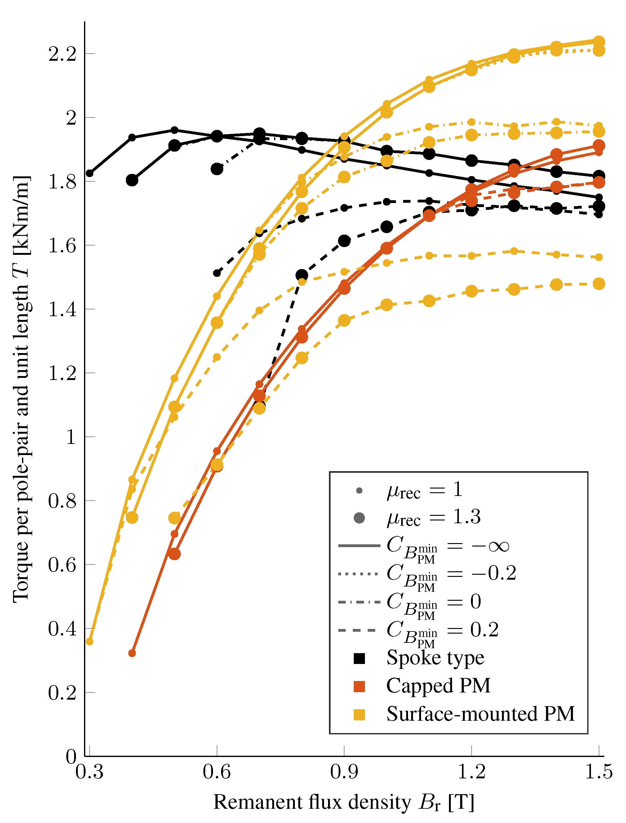
The impact of changing the design to protect the PM from demagnetisation is further shown in Figure 10. The maximum torque obtained for a given PM material is plotted over remanence for two values of recoil permeability and all four values of . The capped PM rotor is most resistant to demagnetisation, making it useful for high materials with low demagnetisation resistance. For this kind of PM material, the capped PM outperforms the other two topologies. The spoke type and surface mounted PM rotor on the other hand show larger sensitivity to demagnetisation. The surface mounted PM rotor has the best performance for high materials that have good resistance against demagnetisation, but, for more sensitive materials, this performance diminishes as the design is adapted to protect the PM. The surface mounted PM rotor is also the only topology that needs to be modified to resist demagnetisation for . For low , below about T, the spoke type rotor gives the highest torque of the three studied topologies. Adaptation to protect the PM from demagnetisation causes the torque that can be produced to drop, especially where it is the highest otherwise, similar to the surface mounted rotor. There are also greater constraints on how high the PM can be made for the spoke type rotor, which prevents the PM shape from being adapted to withstand demagnetisation.
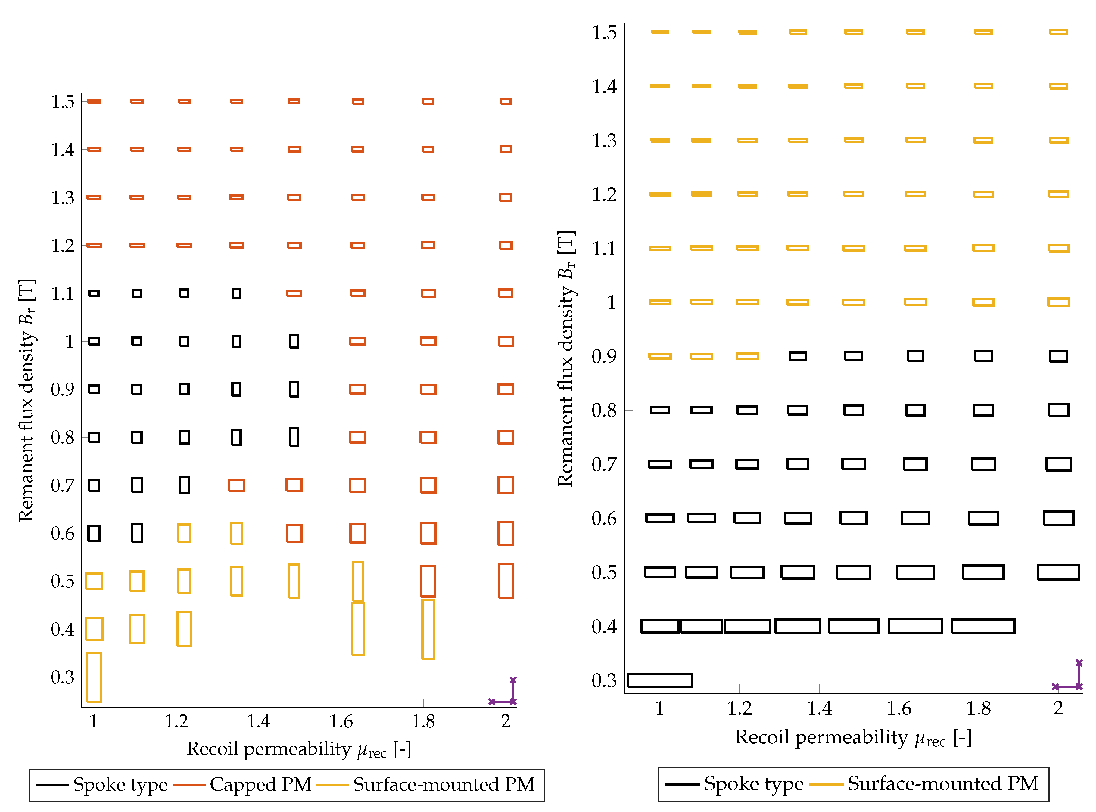
In Figure 11, the shape and size of the PM in the topology with the highest torque, in each material point for and , are shown. It can be seen that higher demagnetisation resistance favours PMs with smaller height and greater width. In the low- points, where the surface mounted PM rotor is the best for , the spoke type rotor cannot accommodate a PM high enough to resist the demagnetisation. The capped PM rotor never gives the highest torque for (right in Figure 11).
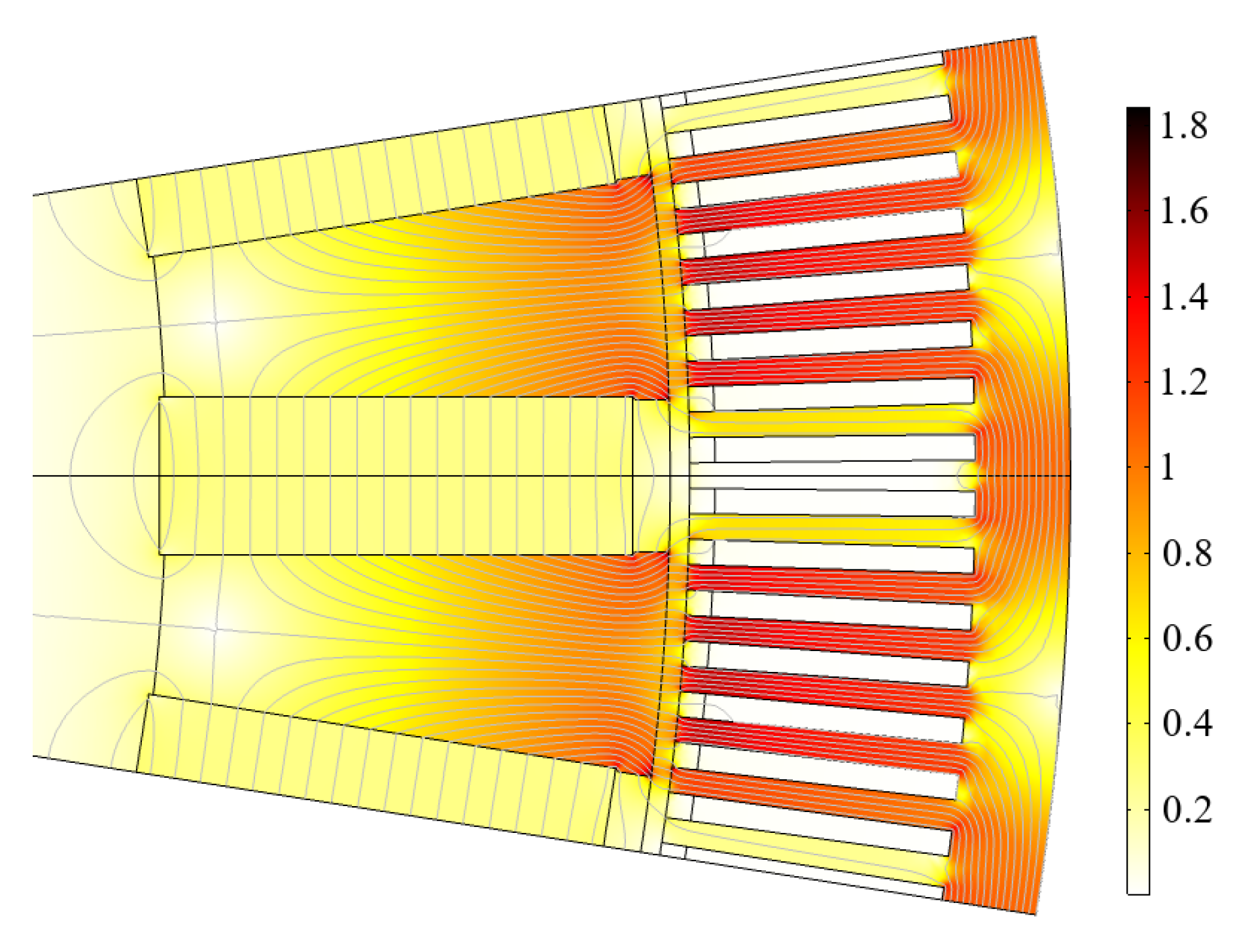
In Figure 12, the magnetic field in the spoke type rotor optimised for , , and is shown. Features of interest are the leakage flux in the region between the PM and the stator; and the radius where the radial component of the magnetic flux in teh pole piece becomes zero, and turns into a leakage flux for smaller radius. Both of these leakage fluxes depend both on the shape of the PM, which has been optimised, but also on the shape of the pole piece, which has not been optimised in this study. The latter is a limitation on the method for the spoke type and capped PM rotors, compared to the surface mounted PM rotor, as the pole shape will have a small impact on the performance that can be obtained. The surface mounted PM rotor does not have this limitation, as it does not have any PM size dependent iron in the rotor, except the rotor back ring which just needs to be thick enough to avoid saturation. A study on performance of generators with different shapes of poles can be found in [28].
The result of the stability analysis is shown in Figure 13. The impact of the parameter changes is given as the arithmetic mean value and standard deviation of point-wise normalised optimised torque in the different cases—both for all points and for each topology on its own. Of most interest in Figure 13 are the standard deviations and the per topology means. The standard deviations show how much the shape, but not scaling of magnitude of the distribution, differs between the cases. The mean of each topology show how that topology has been affected by the change in the parameter. If all the means are the same, or the standard deviation for all the points is small, the value of the parameter changed in that case has small impact on how the different topologies compare to each other.
The number of material points where the optimisation could not be completed, for the reasons mentioned earlier, are not shown in Figure 13. For the case Midpoint, this is 44, out of a total of 192 points. For the other cases, it varies between 38, and 94 in the case ; the second highest number of missing points is 53 for the case . In the case , all but one of the material points are missing for the spoke type rotor, i.e., the geometry does not allow for enough PM material in this case.
The change in propagates to all dimensions of the geometry, except the PM volume, which is given by , and . The capped PM rotor shows the greatest change in mean value, in response to changed , and the surface mounted has the greatest variance. When it comes to changes in , the spoke type is the most sensitive; the mean value for the spoke type changes more than that of the other topologies and, for the largest , the topology is mostly unusable. Changing the number of pole pairs or stator current loading, both give a change in delivered torque that is similar between the different rotor topologies. Change of changes the torque of the spoke type rotor slightly more than it changes the torque obtained from the other two topologies. The slot depth show no change on obtained torque. It could have a rather significant impact on the thermal properties of the machine, but these are not explicitly modelled here.
The stator current loading, , and slot depth , are both stator parameters. Changing either has a similar effect on all three topologies. This indicates that the design of the stator has a limited impact on the relative performance, as measured here in torque production, of the different rotor topologies. Thus, the choice of values of these parameters is of less importance to the results in the study. The number of pole pairs, P, can, by the same line of reasoning, be considered to be of lesser importance to the results (for constant ). With the low impact on the outcome of the choice of values of P, and , the choice of the values matter less to generality of the results obtained.
One problem for the generality of the result is the dependence on the pole pitch which varies greatly depending on the size of the machine. The air gap length also has this problem, but to a lesser extent since manufacturing tolerances imposes a lower limit on it, and the requirement to save PM material gives an incentive not to make it much larger than this. These limits are in relation to the stator bore diameter, see [22] (p. 306), which means that, while the absolute value of can vary a lot, the length relative to the rest of the geometry will not vary that much. In addition, the value of has, in the stability analysis, been tested from the smallest value mechanically feasible, to eight times that value. In this interval, it can be seen that the spoke type rotor is more sensitive to the change in air gap length than the other two rotor topologies. Decreasing allows more torque to be generated than with the other rotor topologies, while, for larger , it cannot reach the required operating point. Despite this drawback, the spoke type rotor outperforms the other rotor topologies for low PMs, at least for air gap lengths up to 1.25 of the default value. The pole pieces in the spoke type rotor and the capped PM rotor are made from soft magnetic material. Making the pole pieces from laminated magnetically soft iron reduces the problems caused by slot-harmonic induced eddy currents in the pole face, which can occur with small air gap lengths. The poor performance of the spoke type rotor with large air gap lengths should therefore not be a problem, as there is no need for a large air gap.
The changes in optimised torque in response to a change in are problematic for the generality of the results. It should, however, be considered that, in most cases, making the machine larger, by increasing , would also mean increasing the volume of PM material used. Per unit length, this means that should increase as to keep the machines geometrically similar, if the same material properties are assumed. The results presented in Figure 13 roughly indicate that the different trends in the altered and cases should cancel each other if is scaled as . There is still the matter of choosing a suitable value for for a given , which also has some effect on the results but less than the impact of changing with constant .
Generally it can be noted that the spoke type rotor is more dependent on the amount of PM material than the other two topologies, which are instead more dependent on of the material. This is supported both by the stability analysis, where the spoke type rotor is the topology most impacted by changes that alters the amount of PM material in relation to the size of the rest of the geometry; and by the main result where the spoke type rotor has a much flatter torque over the and surface than the other two topologies.
5. Conclusions
Three different rotor topologies are optimised for torque production assuming identical stators, resistive load of a given current amplitude, and an equal amount of PM maximum energy for different values of PM material parameters. The parameters are the remanent flux density , recoil permeability , and relative minimum flux density , to model demagnetisation. Optimum torque for each material point and topology is calculated and used to compare the topologies.
It is found that the spoke type rotor achieves the highest torque for low materials. It does, however, have issues with limits on how high the PM can be made, which sometimes makes it impossible to avoid demagnetisation or reach the desired working point. For high material, the surface mounted PM rotor can give the highest torque if the PM material has good resistance against demagnetisation, low ; otherwise, the capped PM, which offers more protection against demagnetisation, performs better. From this, it can be concluded that demagnetisation resistance is more important than remanence in a PM material for use in electrical machines, and that an inexpensive, low material with reasonable demagnetisation resistance can be highly useful in this application—in particular, if it is used with a flux concentrating rotor, such as the spoke type rotor.
A stability analysis was carried out by changing design input parameters, one at a time. This shows that the results are reasonably stable under perturbations of most parameters. Changes in the pole pitch, , air gap length, , and PM maximum energy, , did show potential to cause qualitative changes of the outcome. The air gap length, relative to the rest of the size of the machine, should stay sufficiently close to the used value for the results to have some generality. The value of and should be changed together, as the size of the machine dictates how much PM material can be used. If is adjusted by the square of the relative change in , to preserve similarity, the impact of the change in and that of the change in cancel each other out. The range of values of that can fit into the geometry for a given is rather limited, while the values of can be varied over several orders of magnitude. Overall, the conclusions drawn should have some generality.
Author Contributions
Conceptualization, S.E. and P.E.; methodology, P.E.; software, P.E.; formal analysis, P.E.; investigation, P.E. and S.E.; writing—original draft preparation, P.E.; writing—review and editing, P.E. and S.E.; visualization, P.E.; supervision, S.E.; funding acquisition, S.E.
Funding
This study was carried out with funding from the Swedish Research Council, Grant No. 2012-4706; and from the Carl Trygger Foundation. This work was conducted within the StandUP for Energy strategic research framework.
Conflicts of Interest
The authors declare no conflict of interest. The funders had no role in the design of the study; in the collection, analyses, or interpretation of data; in the writing of the manuscript, or in the decision to publish the results.
Nomenclature
| m | Effective cross section area of winding | |
| m | PM area | |
| A/m | Linear current density | |
| Tm | Magnetic vector potential, axial component | |
| B | T | Magnetic flux density |
| B | T | Remanent magnetic flux density |
| T | Magnetic flux density parallel to B | |
| T | Magnetic flux density, treshold | |
| J/m | Maximum energy product | |
| Demagnetization parameter | ||
| m | Slot depth | |
| m | Stator inner diameter | |
| J | PM maxmimum energy | |
| A | Direct axis MMF | |
| A | Quadrature axis MMF | |
| H | A/m | Magnetising field |
| A/m | Coercivity | |
| A/m | Intrinsic coercivity | |
| m | PM height along magnetization | |
| J | A/m | Current density |
| l | m | Machine length |
| M | A/m | Magnetisation |
| P | Number of pole pairs | |
| t | s | Time |
| T | Nm/m | Torque per pole pair and unit length |
| m | PM width across magnetization | |
| q | Number of slots per pole and phase | |
| Volume fraction | ||
| Volume fraction at SC | ||
| Volume fraction at NL | ||
| Tolerance for volume fraction at SC | ||
| Tolerance for volume fraction at NL | ||
| m | Air gap length | |
| rad | Electrical angle, rotor reference frame | |
| H/m | Permeance per unit length, d-axis | |
| H/m | Permeance per unit length, q-axis | |
| Wb/Am | Permeability of vacuum | |
| Relative permeability | ||
| Relative recoil permeability | ||
| V/m | Voltage per turn and unit length, d-axis | |
| V/m | Voltage per turn and unit length, q-axis | |
| /m | Magnetic load resistance | |
| /m | Magnetic winding resistance | |
| m | Pole pitch | |
| m | Slot pitch | |
| Wb/m | Magnetic flux per unit length, d-axis | |
| Wb/m | Magnetic flux per unit length from PM | |
| Wb/m | Magnetic flux per unit length, q-axis | |
| rad/s | Electrical angular frequency |
References
- Gutfleisch, O.; Willard, M.A.; Brück, E.; Chen, C.H.; Sankar, S.G.; Liu, J.P. Magnetic Materials and Devices for the 21st Century: Stronger, Lighter, and More Energy Efficient. Adv. Mater. 2011, 23, 821–842. [Google Scholar] [CrossRef] [PubMed]
- Lacal-Arántegui, R. Materials use in electricity generators in wind turbines—State-of-the-art and future specifications. J. Clean. Prod. 2015, 87, 275–283. [Google Scholar] [CrossRef]
- Eklund, P.; Sjökvist, S.; Eriksson, S.; Leijon, M. A Complete Design of a Rare Earth Metal-Free Permanent Magnet Generator. Machines 2014, 2, 120. [Google Scholar] [CrossRef]
- Kim, K.C.; Lee, J. The dynamic analysis of a spoke-type permanent magnet generator with large overhang. IEEE Trans. Magn. 2005, 41, 3805–3807. [Google Scholar] [CrossRef]
- Chen, Z.; Spooner, E. A modular, permanent-magnet generator for variable speed wind turbines. In Proceedings of the Seventh International Conference on Electrical Machines and Drives, Durham, UK, 11–13 September 1995; pp. 453–457. [Google Scholar] [CrossRef]
- Spooner, E.; Williamson, A. Direct coupled, permanent magnet generators for wind turbine applications. IEE Proc. Electr. Power Appl. 1996, 143, 1–8. [Google Scholar] [CrossRef]
- Binder, A.; Schneider, T. Permanent magnet synchronous generators for regenerative energy conversion—A survey. In Proceedings of the 2005 European Conference on Power Electronics and Applications, Dresden, Germany, 11–14 September 2005; p. 10. [Google Scholar] [CrossRef]
- Coey, J. Permanent magnets: Plugging the gap. Scr. Mater. 2012, 67, 524–529. [Google Scholar] [CrossRef]
- Delczeg-Czirjak, E.K.; Edström, A.; Werwiński, M.; Rusz, J.; Skorodumova, N.V.; Vitos, L.; Eriksson, O. Stabilization of the tetragonal distortion of FexCo1-x alloys by C impurities: A potential new permanent magnet. Phys. Rev. B 2014, 89, 144403. [Google Scholar] [CrossRef]
- Edström, A.; Chico, J.; Jakobsson, A.; Bergman, A.; Rusz, J. Electronic structure and magnetic properties of L10 binary alloys. Phys. Rev. B 2014, 90, 014402. [Google Scholar] [CrossRef]
- Fang, H.; Kontos, S.; Ångström, J.A.; Cedervall, J.; Svedlindh, P.; Gunnarsson, K.; Sahlberg, M. Directly obtained τ-phase MnAl, a high performance magnetic material for permanent magnets. J. Solid State Chem. 2016, 237, 300–306. [Google Scholar] [CrossRef]
- Kimiabeigi, M.; Sheridan, R.S.; Widmer, J.D.; Walton, A.; Farr, M.; Scholes, B.; Harris, I.R. Production and Application of HPMS Recycled Bonded Permanent Magnets for a Traction Motor Application. IEEE Trans. Ind. Electron. 2018, 65, 3795–3804. [Google Scholar] [CrossRef]
- Torrent, M.; Perat, J.; Jiménez, J. Permanent Magnet Synchronous Motor with Different Rotor Structures for Traction Motor in High Speed Trains. Energies 2018, 11, 1549. [Google Scholar] [CrossRef]
- Arumugam, P.; Dusek, J.; Aigbomian, A.; Vakil, G.; Bozhko, S.; Hamiti, T.; Gerada, C.; Fernando, W. Comparative design analysis of Permanent Magnet rotor topologies for an aircraft starter-generator. In Proceedings of the IEEE International Conference on Intelligent Energy and Power Systems (IEPS), Kiev, Ukraine, 2–6 June 2014; pp. 273–278. [Google Scholar] [CrossRef]
- Wang, A.; Jia, Y.; Soong, W.L. Comparison of Five Topologies for an Interior Permanent-Magnet Machine for a Hybrid Electric Vehicle. IEEE Trans. Magn. 2011, 47, 3606–3609. [Google Scholar] [CrossRef]
- Kim, H.J.; Moon, J.W. Improved rotor structures for increasing flux per pole of permanent magnet synchronous motor. IET Electr. Power Appl. 2018, 12, 415–422. [Google Scholar] [CrossRef]
- Gundogdu, T.; Komurgoz, G. The Impact of the Selection of Permanent Magnets on the Design of Permanent Magnet Machines—A Case Study: Permanent Magnet Synchronous Machine Design with High Efficiency. Przeglad Elektrotech. 2013, 89, 103–108. [Google Scholar]
- Shimizu, Y.; Morimoto, S.; Sanada, M.; Inoue, Y. Influence of permanent magnet properties and arrangement on performance of IPMSMs for automotive applications. In Proceedings of the 2016 19th International Conference on Electrical Machines and Systems (ICEMS), Chiba, Japan, 13–16 November 2016; pp. 1–6. [Google Scholar]
- Eriksson, S.; Bernhoff, H. Inherent Difference in Saliency for Generators with Different PM Materials. J. Renew. Energy 2014, 2014, 567896. [Google Scholar] [CrossRef]
- Eriksson, S.; Bernhoff, H. Rotor design for PM generators reflecting the unstable neodymium price. In Proceedings of the XXth International Conference on Electrical Machines, Marseille, France, 2–5 September 2012; pp. 1419–1423. [Google Scholar] [CrossRef]
- Sjökvist, S.; Eklund, P.; Eriksson, S. Determining demagnetisation risk for two PM wind power generators with different PM material and identical stators. IET Electr. Power Appl. 2016, 10, 593–597. [Google Scholar] [CrossRef] [Green Version]
- Pyrhönen, J.; Jokinen, T.; Hrabovocová, V. Design of Rotating Electrical Machines, 2nd ed.; John Wiley and Sons: Hoboken, NJ, USA, 2014; pp. 298–308. [Google Scholar]
- Binns, K.; Kurdali, A. Permanent-magnet a.c. generators. Inst. Electr. Eng. 1979, 126, 690–696. [Google Scholar] [CrossRef]
- Jun, C.S.; Kwon, B.I. Performance comparison of a spoke-type PM motor with different permanent magnet shapes and the same magnet volume. IET Electr. Power Appl. 2017, 11, 1196–1204. [Google Scholar] [CrossRef]
- Arkkio, A. Analysis of Induction Motors Based on the Numerical Solution of the Magnetic Field and Circuit Equations. Ph.D. Thesis, Helsinki University of Technology, Espoo, Finland, 1987. [Google Scholar]
- Eklund, P.; Eriksson, S. Winding Scheme Independent Method for Prediction of Short Circuit Current Distribution for a PMSM. In Proceedings of the XXIIIrd International Conference on Electrical Machines, Alexandroupoli, Greece, 3–6 September 2018. [Google Scholar]
- Rumble, J.R. (Ed.) CRC Handbook of Chemistry and Physics; Chapter Electrical Resistivity of Pure Metals, (Internet Version 2018); CRC Press/Taylor & Francis: Boca Raton, FL, USA, 2018. [Google Scholar]
- Ranlöf, M.; Lundin, U. Form Factors and Harmonic Imprint of Salient Pole Shoes in Large Synchronous Machines. Electr. Power Compon. Syst. 2011, 39, 900–916. [Google Scholar] [CrossRef]
Figure 1.
The second quadrant demagnetisation curve of the PM material in terms of the material parameters used: remanent flux density , recoil permeability , and the demagnetisation parameter . B is magnetic flux density, M is magnetisation, H the applied magnetic field, and the intrinsic coercivity.

Figure 2.
The geometry of the stator, only showing the two poles needed for symmetry. The grey shaded area is steel. Black shaded areas are the armature winding. The dot-dashed lower boundary represents the rotor surface. The white parts of the geometry are occupied by air.
Figure 2.
The geometry of the stator, only showing the two poles needed for symmetry. The grey shaded area is steel. Black shaded areas are the armature winding. The dot-dashed lower boundary represents the rotor surface. The white parts of the geometry are occupied by air.

Figure 3.
One pole of the surface mounted PM rotor. The dashed lines on the sides are the inter pole boundary. The dotted lines are simulation geometry boundaries. The grey shaded areas are the iron of the rotor back ring and parts of the stator. The light grey areas hatched with arrows are the PMs, with the arrows indicating the direction of magnetisation for a north pole. The white parts of the geometry are occupied by air.

Figure 4.
One pole of the capped PM rotor geometry. The dashed lines on the sides are the inter pole boundary. The dotted lines are simulation geometry boundaries. The grey shaded areas are the iron of the rotor back ring, the pole shoe and steel parts of the stator. The light grey area hatched with arrows is the PM, with the arrows indicating the direction of magnetisation for a north pole. The white parts of the geometry are occupied by air.

Figure 5.
One pole of the spoke PM rotor geometry. The dashed line at the top is the inter pole boundary. The dotted lines are simulation geometry boundaries. The grey shaded areas are the iron of the pole pieces and parts of the stator. The light grey areas hatched with arrows are the PMs, with the arrows indicating the direction of magnetisation for the magnets surrounding a north pole. The white parts of the geometry are occupied by air.

Figure 6.
The boundary conditions (BC) used, the rotor part of the geometry has been hatcheted. Simulations are performed for two poles.
Figure 6.
The boundary conditions (BC) used, the rotor part of the geometry has been hatcheted. Simulations are performed for two poles.

Figure 7.
The B-H curve of the soft iron used for stator steel and all iron parts in the simulations.
Figure 7.
The B-H curve of the soft iron used for stator steel and all iron parts in the simulations.

Figure 8.
Example of a mesh from the simulations, here shown for a generator with spoke type rotor.

Figure 9.
Contour plot of torque per pole pair and unit length as a function of remanence and recoil permeability . The left column is for and the right column is for . The colour scale is shared between plots in the same column. The differences between two contour lines are Nm/m and Nm/m for the left and right columns, respectively. The asterisk indicates the point of highest torque for each plot.

Figure 10.
Torque per pole pair and unit length over remanent flux density for two different recoil permeabilities (indicated by marker size), four different demagnetisation sensitivities (indicated by line style), and the three topologies (indicated by line colour).
Figure 10.
Torque per pole pair and unit length over remanent flux density for two different recoil permeabilities (indicated by marker size), four different demagnetisation sensitivities (indicated by line style), and the three topologies (indicated by line colour).

Figure 11.
Shape of the PMs in the rotor topology that gives the highest torque for each pair of and . Vertical length corresponds to PM height (along magnetisation) and width to PM width . Colour of box indicates which topology gives the highest torque. The demagnetisation resistances shown are to the left and to the right. The purple angle in the lower right corner indicates the length of the pole pitch .

Figure 12.
The magnetic flux density in the optimised spoke type rotor for a material point with and at no load. Field lines and magnitude in [T] are shown.
Figure 12.
The magnetic flux density in the optimised spoke type rotor for a material point with and at no load. Field lines and magnitude in [T] are shown.

Figure 13.
Optimised torque, normalised point-wise by the Midpoint case, of the different cases of the stability analysis. The large marker indicates the arithmetic mean value for each topology, or all of them together. The lines and small markers show mean±standard deviation. Cases are denoted by the parameter changed and how it was changed. Points where the optimisation failed have been removed.


Table 1.
Properties of commercially available PM materials. Data compiled from data sheets of various PM manufacturers, for temperatures in the range of 20 to 30 . is the intrinsic coercivity of the PM, for alnico PMs, the normal coercivity is given instead (as the data sheets does not give ). No is given for alnico since that class of materials is usually used on a demagnetisation minor loop and therefore depends on which minor loop is chosen. When is not given, it is estimated by , i.e., by assuming that the energy maximum occurs in the linear part of the magnetisation curve, estimated are marked with a “*”.
| Material Family | |||||
|---|---|---|---|---|---|
| [T] | [kA/m] | [kJ/m] | [-] | [-] | |
| Alnico | 0.55–1.37 | 38–151 | 10.7–83.6 | 1.3–6.2 | - |
| Hard ferrite | 0.20–0.46 | 140–405 | 6.4–41.8 | 1.05–1.2 | –0.4 |
| Nd-Fe-B | 1.08–1.49 | 876–2710 | 220–430 | 1.0–1.1 * | −2.3–0.2 |
| Sm-Co | 0.87–1.19 | 1350–2400 | 143–251 | 1.0–1.1 * | −2.7–−0.62 |
Table 2.
The relationships between the geometrical parameters and their default values.
| Quantity | Symbol | Expression | Value |
|---|---|---|---|
| Pole pitch | - | 80 mm | |
| Number of pole pairs | P | - | 20 |
| Number of slots per pole | q | - | 15/2 |
| Stator inner diameter | 1.02 m | ||
| Air gap length (mechanical) | 4.07 mm | ||
| Slot pitch | 10.7 mm | ||
| Slot depth | 60 mm | ||
| PM height, along magnetisation | Set by optimiser | ||
| PM width, across magnetisation | Set by optimiser | ||
© 2019 by the authors. Licensee MDPI, Basel, Switzerland. This article is an open access article distributed under the terms and conditions of the Creative Commons Attribution (CC BY) license (http://creativecommons.org/licenses/by/4.0/).
Share and Cite
MDPI and ACS Style
Eklund, P.; Eriksson, S. The Influence of Permanent Magnet Material Properties on Generator Rotor Design. Energies 2019, 12, 1314. https://doi.org/10.3390/en12071314
AMA Style
Eklund P, Eriksson S. The Influence of Permanent Magnet Material Properties on Generator Rotor Design. Energies. 2019; 12(7):1314. https://doi.org/10.3390/en12071314
Chicago/Turabian StyleEklund, Petter, and Sandra Eriksson. 2019. "The Influence of Permanent Magnet Material Properties on Generator Rotor Design" Energies 12, no. 7: 1314. https://doi.org/10.3390/en12071314
Note that from the first issue of 2016, this journal uses article numbers instead of page numbers. See further details here.