Elimination of Common Mode Voltage in Three-To-Six-Phase Matrix Converter


Department of Power Electronics and Power Engineering, Rzeszow University of Technology, 35-959 Rzeszów, Poland
*
Author to whom correspondence should be addressed.
Energies 2019, 12(9), 1662; https://doi.org/10.3390/en12091662
Submission received: 17 March 2019
/
Revised: 28 April 2019
/
Accepted: 29 April 2019
/
Published: 1 May 2019
(This article belongs to the Special Issue Control in Power Electronics)
Abstract
:The matrix converter (MC) is the n-phase input and m-phase output power electronic system. To synthesis the controllable sinusoidal output voltage and input current with controllable input displacement angle, the pulse width modulation method (PWM) is used in the MC. During the modulation process a problem of the common mode voltage (CMV) exists. The elimination of the CMV in three-to-six-phase MC by usage of only rotating voltage space vectors is analyzed in the paper. The carrier based implementation of the space vector modulation (SVM) with Venturini modulation functions is applied to the control of the three-to-six-phase MC. Entire elimination of the CMV in three-to-six-phase MC is presented in the paper. The simulation and experiment results confirm utility of the proposed modulation method.
1. Introduction
Matrix converter (MC) is a direct AC/AC converter that is used to convert available AC supply into desirable AC outputs with variable voltage and variable frequency. Advantages commonly associated with the MC are: Sinusoidal input current and output voltage, input power factor control, regeneration capability, and compact circuitry. The synthesis of referenced sinusoidal output voltage and sinusoidal input current with controllable input displacement angle is the main goal in the modulation method used in controlling MCs. The control method of m-phase-to-n-phase MC, realizing requested output voltage and demanded input current, was worked out by inventors of the MC and authors of first papers published in eighties of previous century [1,2]. The authors of References [1,2] propose two types of modulation signals used in the carrier based pulse width modulation (PWM) control method. The next, many modulation methods in controlling of the MC, were developed. These methods were analyzed for the three-phase-to-three-phase MC and may be grouped as follows: Space vector modulation methods, scalar modulation methods, predictive control method, and carrier based modulation method.
In the last decade the multiphase topologies of the MC are investigated. The interest of the multiphase structure of the MC was dictated by development of multiphase drives, supplied by back-to-back converters. The MC, compared with the back-to-back converter, offers some advantages, like smaller size, bidirectional power flow and controllable input displacement angle. The multiphase (more than three) motor drives have some inherent advantages over the traditional three phase motor drives. To these advantages belong, among others: Increasing the frequency and reducing the amplitude of torque pulsations, reducing the rotor harmonic currents losses, decreasing acoustic noise, and lowering current per phase. Additionally, the multiphase motor drives improve the system reliability owing to their redundant structure. If one phase of the multiphase machine becomes open circuited, it will still self-start and will run with only minimal de-rating. These advantages make the multiphase machines suitable for propulsion of electric cars, locomotives, ships, and aircraft. Many features of the multiphase drives are discussed in Reference [3].
Multiphase MC as a counterpart of the back-to-back converter in the multiphase drive is analyzed mainly in application into odd number of motor phases. The authors of the References [4,5,6] apply the space vector modulation method into three-phase-to-odd-phase MCs. The performances of three-phase-to-odd-phase MCs controlled with use of the carrier based modulation method are investigated in the papers [7,8,9,10,11,12,13]. Little attention has been paid to the development of MCs with even phase outputs [14,15,16,17].
Different methods have been reported to mitigate detrimental influences of the CMV for MCs [18,19,20,21]. The majority of the methods are based on the modification of the SVM by elimination of the zero space vector as a complement of the switching cycle. These methods allow reducing the peak values of the CMV merely, whereas the author of the Reference [22] has proposed the entire elimination of the CMV in the MC. The proposed method is based on use solely rotating voltage space vectors in synthesis of the output voltage in the MC. Likewise, total elimination of the CMV, in reference to the dual MC, obtained by application of rotating voltage space vectors is presented in [23,24,25].
Thus this paper focuses on the investigation of the topology of the MC which is a single stage power converter realizing a six-phase supplying source. Specially, the main goal of this paper is to describe the modulation method, which eliminates entirely the CMV in the three-to-six-phase MC. To solve the problem of the elimination of the CMV in the three-to-six-phase MC, the application of the modulation method using solely rotating space vectors is proposed in the paper. To determine the switch duty cycles of the three-to-six-phase MC the carrier-based implementation of the space vector modulation is used [26,27]. The elaboration of the proposed method required the analysis of admissible MC configurations, depending on on/off states of bidirectional switches. The MC configurations, and voltage space vectors, providing the synthesis of the required output voltage and realizing the elimination of the CMV, were selected and presented in the paper. Simulation and measurement tests, prepared with consideration of the three different load configurations supplied by the three-to-six-phase MC, evaluate the proposed modulation method.
2. Three-To-Six Matrix Converter
2.1. Topology of Multiphase Matrix Converter
The multiphase drive is addressed into high power load. The most frequently considered multiphase machine for high power applications is the asymmetrical six-phase induction machine, that the stator has two sets of three-phase windings, spatially shifted by 30 electrical degrees [4], while the rotor winding is of squirrel cage type and is the same as for a three-phase machine. The six-phase induction machine needs six-phase input voltage source, which would be realized by application of the three-to-six-phase matrix converter. The power circuit topology of the MC (Figure 1) consists of six legs with each leg having three bidirectional power switches, so the total number of the switches is 18. Switching function of bidirectional switch is defined as (1). Taking the number of the switches into account, the total number of switching states combinations is 218. For the MC to operate safely, the following constraints must be adhered to, i.e., the input phases should never be shorted, and the output phases should never be opened at any instant. It means that only one of three switches connecting given output phase with three input phases must be switched on (2). Considering these constraints for the three-to-six-phase MC, the number of valid switching states is 36, i.e., there are 729 different switching combinations for connecting the six output phases to the three input phases.
The relation of the output voltages to the input voltages , and the input currents to output currents may be defined in terms of switching states as follows (3, 4).
The output voltage in the three-to-six-phase MC can reach up to 75% of the input voltage, which is the physical limit of this MC [9,16]. The modulation method, presented in the paper, assumes the 50% value of voltage transfer ration. This low value of voltage transfer ratio results from the fact, that the presented in the paper modulation method is focused on obtaining entire elimination of the CMV, what demands to apply only rotating voltage space vectors, and it is connected with limitation of the maximum obtainable output voltage in MC [22,24,27].
2.2. Output Voltage Space Vectors in Three-to-Six-Phase MC
The output voltages of the three-to-six-phase MC could be presented using space vectors, defined by (5). Each of instantaneous output voltages: u1, u2, u3, u4, u5 and u6 in the relation (5) is equal, appropriately, one of the input phase voltage: ua, ub or uc. The label xxxxxx in the name of the space vector means the name of input phase chosen into output phase 1, 2, 3, 4, 5, and 6, appropriately.
where: .
The switching combinations for connecting the six output phases to the three input phases in the three-to-six-phase MC can be analyzed in seven groups. The switching combinations are named as {x,y,z}, where x, y, and z represent the number of output phases connected to input phase A, phase B, and phase C, respectively.
- {6,0,0} All of the output phases are connected to the same input phase. This group consists of three possible switching combinations, i.e., either all output phases are connected to input phase A or input phase B or input phase C. {6,0,0} represents the switching conditions when all of the output phases are connected to input phase A. {0,6,0} represents the switching conditions when all of the output phases are connected to input phase B. {0,0,6} represents the switching conditions when all of the output phases are connected to input phase C. The voltage space vectors, representing these switching combinations have zero module and frequency. These are called zero vectors.
- {5,1,0} Five of the output phases are connected to the same input phase, and the sixth output phase is connected to any of the other two input phases. Here, 5 means five different output phases are connected to input phase A. The number 1 means that one output phase, other than the previous five, is connected to input phase B, and input phase C is not connected to any output phase. As such, there exist six different switching states ({5,1,0}, {1,5,0}, {1,0,5}, {0,1,5}, {0,5,1}, and {5,0,1}). Out of these, one switching state can have further six different combinations, i.e., every switching state has six combinations. This group hence consists of 6 × 6 = 36 switching combinations in all. Voltage space vectors representing these switching combination have a changeable module with maximum value amplitude of input phase voltage (6)), and fixed position on the complex plane. Here, all of switching combinations correspond to the active voltage space vectors.
- {4,0,2} Four of the output phases are connected to the same input phase and remaining two phases are connected to any of the other two input phases. Here exist six different switching states: {4,0,2}; {4,2,0}; {2,4,0}; {2,0,4}; {0,4,2}; and {0,2,4}. Every of sub-group have (6!/(4! × 2!)) × (2!/(2! ×0!)) = 15 combinations. Thus the total possible combination will be 6 × 15 = 90 switching combinations. The voltage space vectors in this group could be split up into three groups: 18 zero space vectors; 36 active voltage space vectors with a changeable module with maximum value and 36 active voltage space vectors with maximum value of the module equal the amplitude of input voltage .
- {4,1,1} Four of the output phases are connected to the same input phase and the two other output phases are connected to the other two input phases, respectively. As such, there exist three different switching states ({4,1,1}, {1,4,1}, and {1,1,4}). One sub-group can have (6!/(4! × 2!)) × (2!/(1! × 1!)) = 30 combinations. There are 3 sub-groups and thus the total possible combination will be 3 × 30 = 90 switching combinations. Among these 90 switching combinations 18 are represented by the active space voltage vectors with a changeable module with maximum value ; 36 are represented by rotating space voltage vectors with constant module equal and 36 combinations correspond to the space vectors with changeable both module and position on the complex plane.
- {3,0,3} Three of the output phases are connected to the same input phase and remaining three output phases are connected to another input phase. As such, there exist three different switching states: {3,3,0}, {0,3,3}, and {3,0,3}. One sub-group can have (6!/(3! × 3!)) × (3!/(3! × 0!)) = 20 combinations. There are 3 sub-groups and thus the total number of possible combination will be 3 × 20 = 60 switching combinations. In this group there are 6 zero space voltage vectors, 18 active voltage space vectors with a changeable module, with maximum value and 36 active space voltage vectors with maximum value of the module .
- {3,2,1} Three of the output phases are connected to the same input phase, two of them are connected to the same another input phase and the sixth output phase is connected to the third input phase. There exist six different switching states: {3,1,2}; {2,3,1}; {2,1,3}; {1,2,3}; {1,3,2} and {3,2,1}. One sub-group can have (6!/(3! × 3!)) × (3!/(2! × 1!)) × (1!/(1! × 0!)) = 60 combinations. There are 6 sub-groups and thus the total possible number of combination will be 6 × 60 = 360 switching combinations. Among these 360 switching combinations 72 are represented by rotating voltage space vectors with constant module equal , 144 switching combinations correspond to two groups of active voltage space vectors: with maximum value of module equal and second group—with maximum value of module equal . The next 144 switching combination are represented by the space vectors with changeable both, magnitude and position on the complex plane.
- {2,2,2} To every one input phases the two output phases are connected. One sub-group may have (6!/(2! × 4!)) × (4!/(2! × 2!)) × (2!/(2! × 0!)) = 90 combinations. As such, there is one sub-group and thus the total possible combination will be 1 × 90 = 90 switching combinations. In this group the active voltage vectors exist in the number of 36. Their maximum module is for 18 of them and − for the next 18. There are also 38 voltage space vectors with changeable both module and position on the complex plane and 6 zero vectors and 12 rotating voltage space vectors with modules equal .To sum up, among 729 possible switching combinations there are:
- 360 combinations with active voltage space vectors characterized by changeable modules and fixed position on the complex plane;
- 218 combinations with changeable both module and position on the complex plane;
- 33 zero vectors;
- 118 rotating space vectors with constant modules and constant angle speed on complex plane, half of them rotate in the negative direction (CW vectors), and the next half—in the positive direction (CCW vectors).
2.3. Output Voltage Space Vectors Reducing CMV in the Three-to-Six-Phase MC
Amongst all 118 rotating space vectors a special remark, in context of the CMV elimination, should be returned on 12 rotating voltage space vectors (Table 1) and 6 zero vectors (Table 2) in the seventh group described in Section 2.2. Only these 12 rotating voltage space vectors and 6 zero vectors (Table 2) could be used in control, realizing the elimination of the CMV in the three-to-six-phase MC. This conclusion is drawn from the analysis of all 729 space vectors, determined with assumption that the three-to-six-phase MC is supplied by balanced input voltage (6). The lay-out of the chosen rotating voltage space vectors in a complex plane is shown in the Figure 2. In Figure 2 the initial position of rotating space vectors is shown.
In the presented paper the application of three-to-six-phase MC to supplying six-phase load is investigated. The CMV for the six-phase output voltage of MC is defined in (7). The application of the rotating voltage space vectors (Table 1) and zero vectors (Table 2) in modulation of the switch duty cycles, results in zero value of the CMV, which for rotating voltage space vector , and for zero voltage space vector , as examples, are shown in relation (8) and (9). The modules of the zero voltage space vectors are equal zero. Nonetheless, these vectors are not typical zero vectors where all output phases are connected to the same input phase like in switching combinations mentioned in group one. Here all input phases participate in shaping of the voltage in each output phases.
Apart from application of the three-to-six-phase MC to the typical six-phase load, this MC may be used to supply the six-phase load which phases are connected in two star points like in the asymmetrical six-phase induction machine, where the stator has two sets of three-phase windings, spatially shifted by 30 electrical degrees [4]. The respective sets of three-phase winding should be supplied by voltages of the three MC output phases with odd numbers and even numbers, appropriately. Taking into account the switching combination of the MC, corresponding to the distinguished rotating voltage space vectors, and the zero voltage space vectors, the space vector and representing the voltages supplying the load connected in two sets with separated star points, could be calculated as per (10) (Table 1, Table 2).
The Table 1 and Table 2 consist also voltage space vectors for when the MC supplies the three phase open-end machine. To provide proper phase voltage displacement, the machine should be supplied by the MC output voltages: u14, u36, u52. The voltage space vectors representing these voltages are calculated in accordance with (11). All these space vectors are rotating vectors providing elimination of the CMV.
The performed analysis of all allowable switching combinations of the three-to-six-phase MC and corresponding voltage space vectors allow to choose the vectors synthesizing sinusoidal output voltage, sinusoidal input current and eliminating the CMV. As a result, the proposed modulation method is based on application solely the switching combinations belonging to seventh group, that correspond to the rotating voltage space vectors with magnitudes equal . The rotating space vectors are not usually used in modulation strategies, because they lay in different position, so it is difficult to create a repetitive pattern. However, in References [22,27] one can find that implementation of Venturini modulation function for determination of switch duty cycles in the conventional MC and in the Multilevel Matrix Converter could provide the control with use of only rotating voltage space vectors with elimination of the CMV. By analogy, the Venturini modulation functions are used in proposed strategy for modulation duty cycles in the three-to-six-phase MC.
3. Proposed Modulation Method
Synthesis of the output voltage with use of rotating voltage space vectors could be realized by applying carrier-based implementation of the SVM. To set out the switch duty cycles Snl the Venturini modulation functions are used in proposed method. In the case of the three-to-six-phase MC with symmetric sinusoidal input voltages (6) and sinusoidal output voltage with output amplitude and angular frequency indicated as , the Venturini modulation functions are denoted in relationships (12, 13, 14).
It is easy to see that if the MC synthesizes the output and input waveforms with the input displacement angle (parameter ) there are six groups consisting of three identical modulation functions (15). The similar situation is when the parameter , then the synthesized input current has the displacement angle opposite than output phase shift: , and some of the modulation functions also are the same as another (16). The application of the carrier based pulse width modulation allows for some arbitrariness in switch duty cycles order during the switching period Ts. The same waveform of some modulation functions make possible such arrangement of the switch duty cycles during the switching period, that ensures usage the rotating voltage space vectors only.
The exemplary arrangement of the switch duty cycles during the period Ts is shown in the Figure 3. While the modulation functions is defined by (15) the output voltages are represented by rotating space vectors named as CCW type, and lagging input displacement angle. The application of the modulation function (16) gives CW output voltage rotating space vectors and leading input displacement angle [28]. Both of them, i.e., modulation function (15) depending on difference: of output and input frequency and modulation function (16) depending on sum: result in output voltage amplitude equal to half of input voltage amplitude, at most.
4. Simulation and Experiment
4.1. Simulation
Simulation tests were realized in an EMTP-ATP program. The matrix of the bidirectional switches was modelled as a matrix of the ideal bidirectional switches, controlled using signals generated in TACS subroutine. The supply grid is represented by ideal sinusoidal voltage sources, with an RMS value of 220 V and a frequency of 50 Hz, while the load consists in star-connected resistance and inductance elements, with values of 2 Ω and 10 mH per phase. The six-phase load emulates six phase machine stator. Three different cases of the application of the three-to-six-phase MC to supplying induction machine are analysed. One of them is when the MC supplies the six-phase induction machine with common star point (Figure 4a); the next, when the MC powers the six-phase machine with two isolated star points (Figure 4b), and third case is concerned with supplying the three phase open-end induction machine (Figure 4c).
The carrier frequency is fcarr = 5 kHz. Two PWM control methods are tested, one with use of modulation functions (15) and the CCW rotating voltage space vectors, what results in a lagging input displacement angle at the converter inputs. The second method utilizes the modulation functions (16) and the CW rotating voltage space vectors, which results in leading input displacement angle. The referenced voltage transfer ratio kU = 0.5 for all presented results of simulation.
For the six-phase load with common star point (Figure 4a) the results of the simulations are shown in the Figure 5 and Figure 6. The next, the Figure 7 and Figure 8 deal with the case when the MC powers the six-phase machine with two isolated star points (Figure 4b), and third case, concerned with supplying the three phase open-end induction machine (Figure 4c) is illustrated by the waveforms depicted in the Figure 9, Figure 10 and Figure 11.
For all analysed cases the same trait is characteristic – the common mode voltage is entirely eliminated (Figure 5a, Figure 6a, Figure 7a, Figure 9a,b, and Figure 10a). The circular trajectories of output voltage space vector (Figure 5b, Figure 6b, Figure 7b, Figure 8a,b, Figure 9a and Figure 10b), adequately to sinusoidal input voltage, indicates that the synthesis of output voltage is realized with use of rotating space vectors. The module of the rotating voltage space vectors, representing six-phase output voltages (Figure 5b, Figure 6b and Figure 7b) is equal , while for three-phase output (Figure 8a,b) is equal (Table 1). For six-phase voltage (Figure 5b, Figure 6b and Figure 7b) the placement of zero vectors could be observed. These zero vectors, depicted in Table 2, are characterized by zero value of the module for six-phase voltage. For the same switching configuration the module of the vectors representing three of six phases is different than zero, what could be observed for case when the MC is used in supplying two sets of the six phase machine with two isolated star points (Figure 8). In both cases the zero vectors can be categorized as the rotating voltage space vectors, and they do not have negative impact on elimination of the CMV.
For the case when the three-to-six-phase MC is applied to supply the open-end load, in the Figure 9, and Figure 10 the waveforms of the MC phase output voltages (Figure 9) and load phase voltage (Figure 10a) are depicted. In the same figure it could be seen the zero value of the CMV as well as for voltages of three MC output phases (Figure 9) and also for three load phases (Figure 10a). In the trajectory of the load voltages (Figure 10b) could be observed the zero vectors, like for voltages of six output phases, and that the magnitude of rotating voltage space vectors is equal (Table 1).
The analysis of load voltages allows to note, that the amplitude of basic component of this voltage is the same as amplitude of supplying voltage (Figure 10), while the referenced voltage transfer ratio used in control of the MC is kU = 0.5.
4.2. Experiment
To further verify the proposed control method, measurement tests were performed. The experimental parameters are shown in Table 3. The laboratory station (Figure 12) is the universal research station provided for testing different configurations of the MC with use of different control methods, applying different modulation methods. The station consists of two three-to-three MC modules, what allows for testing the classic scheme of three-to-three-phase MC, the three-to-six-phase MC, the six-to-three-phase MC, the two-modules MC supplying open-end load and the multilevel MC with clamp capacitors. The research station works under control of computer, where the modulation methods, applied in control system is encoded. The control system is based on digital signal processor TMS320F2812, determining the duty cycles of bidirectional switches, and programmable logic device. The CPLD provides the generation of controlling signals with taking four-step commutation into account, proper succession the switches duty cycles during switching period, and protection system.
In the laboratory test the three-to-six-phase MC is used to supply the three-phase open-end load (Figure 13). The chosen results of measurement are presented in the Figure 14 and Figure 15.
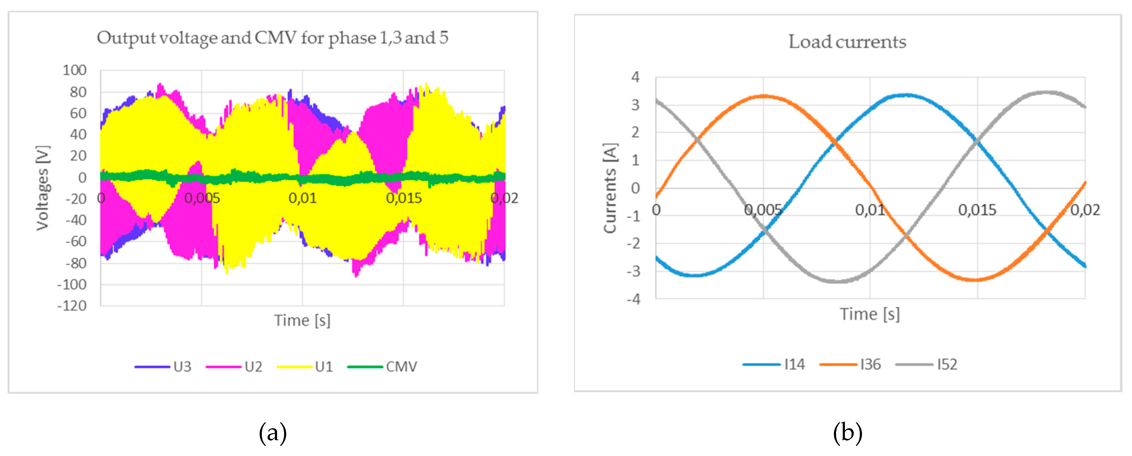
Presented in Figure 14 and Figure 15, waveforms represent the results of measurements concerned with the two method of modulation. In first of the method (Figure 14), the PWM modulation is realised with use of modulation functions (15) what is concerned with referenced input displacement angle the same as load phase angle (). In the second one (Figure 15), the modulation functions (16) are used, and referenced input displacement angle fulfil the condition: . The waveform of output voltage for three phases, supplying the load at the one side (Figure 14a and Figure 15a), and the load current (Figure 14b and Figure 15b) confirm correctness the proposed modulation method—the presented waveforms of current are sinusoidal. Additionally, the elimination of the CMV was obtained (Figure 14a and Figure 15a). The maximum value of the CMV peak voltage did not exceed 5% of input voltage amplitude.
5. Conclusions
The control method of the three-to-six-phase MC, applied to supply the six-phase induction machine, with common star point, and to the six-phase machine with two isolated star points, and to the three-phase open-end machine, was investigated. All 729 admissible switching combinations for connecting the six output phases to the three input phases of MC were analysed, to find the voltage space vectors eliminating the CMV. There was found that 18 configurations fulfill the posited condition. The output MC voltages synthesized in 18 found configurations are represented by the six CCW, and six CW rotating voltage space vectors, and six zero space vectors while the MC supplies the six-phase machine with common star point. In case of the application of the MC to supply the six-phase induction machine with two isolated star points, half of the 18 configurations are represented by the CCW rotating voltage space vectors and half of them correspond to the CW rotating voltage space vectors. These vectors represent the output voltages of MC. In case of the open-end three-phase machine, the voltage space vectors represent the load phase voltage.
The carrier-based implementation of space vector modulation (SVM) was used to control of analyzed MC. As a modulation functions the modified Venturini modulation functions were chosen. The carrier-based SVM, using Venturini modulation functions, is valuable for control of the three-to-six-phase MC. The advantage of proposed strategy is a significant simplification of the MC control. The carrier based implementation of SVM is an alternative way to achieve SVM, that does not involve the knowledge of space vectors when it is derived. Additionally, it avoids any trigonometric and division operations that could be needed to implement the SVM using the general space vector approach. Implementation of Ventutini modulation functions, proposed by the authors of the paper, results in synthesis of output voltage with use of only rotating voltage space vectors, what is precondition to entire elimination of CMV.
The entire elimination of the CMV is an important achievement, obtained by implementation of the proposed modulation method. The elimination of CMV was confirmed by the results of simulation and measurement tests. In the experiment, the peak value of the CMV is less than 5% of the amplitude of the supplying voltage and the peak value of the output voltage. The three-to-six-phase MC controlled with entire elimination of the CMV could be applied in high power six-phase drive.
The drawback of the proposed controlling method is the assumption that the control of the MC is realised with fixed value of input displacement angle—with the lagging or leading one. It could be overcome by applying the modulation method with use of the both modulation functions proposed here for switching time divided proportionally to the value of the referenced input displacement angle. This modulation method will be investigated by the authors soon.
Author Contributions
Conceptualization, J.R.; Formal analysis, J.R. and. E.S.; Investigation, J.R. and E.S.; Methodology, J.R.; Software, J.R. and E.S.; Supervision, J.R.; Validation, J.R.; Visualization, J.R. and E.S.; Writing—original draft preparation, J.R.; Reviewing text J.R. and E.S.
Funding
This research received no external funding.
Conflicts of Interest
The authors declare no conflict of interest.
References
- Alesina, A.; Venturini, M. Analysis and Design of Optimum–Amplitude Nine–Switch Direct AC–AC Converters. IEEE Trans. Power Electron. 1989, 4, 101–112. [Google Scholar] [CrossRef]
- Alesina, A.; Venturini, M. Solid–State power conversion: a Fourier analysis approach to generalized transformer synthesis. IEEE Trans. Circuits Syst. 1981, 28, 319–330. [Google Scholar] [CrossRef]
- Levi, E.; Bojoi, R.; Profumo, F.; Toliyat, H.A.; Williamson, S. Multiphase induction motor drives—A technology status review. IET Electr. Power Appl. 2007, 1, 489–516. [Google Scholar] [CrossRef]
- Ahmed, S.M.; Iqbali, A.; Abu-Rub, H.; Khan, M.R. Space vector PWM technique for a novel three-to-five phase matrix converter. In Proceedings of the 2010 IEEE Energy Conversion Congress and Exposition, Atlanta, GA, USA, 12–16 September 2010; pp. 1875–1880. [Google Scholar] [CrossRef]
- Iqbal, A.; Ahmed, S.M.; Abu-Rub, H. Space Vector PWM Technique for a Three-to-Five-Phase Matrix Converter. IEEE Trans. Ind. Appl. 2012, 48, 697–707. [Google Scholar] [CrossRef]
- Ahmed, M.; Abu-Rub, H.; Salam, Z.; Kouzou, A. Space vector PWM technique for a novel three-to-seven phase matrix converter. In Proceedings of the IECON 2013-39th Annual Conference of the IEEE Industrial Electronics Society, Vienna, Austria, 10–13 November 2013; pp. 4949–4954. [Google Scholar] [CrossRef]
- Ahmed, S.M.; Iqbal, A.; Abu-Rub, H. Generalized Duty-Ratio-Based Pulsewidth Modulation Technique for a Three-to-k Phase Matrix Converter. IEEE Trans. Power Electron. 2011, 58, 3925–3937. [Google Scholar] [CrossRef]
- Saleh, M.; Iqbal, A.; Ahmed, K.M.; Kalam, A.; Abu-Rub, H. Carrier-based pulse width modulation technique for a three-to-five phase matrix converter for supplying five-phase two-motor drives. Int. J. Eng. Sci. Technol. 2010, 2, 67–78. [Google Scholar] [CrossRef]
- Ahmed, S.M.; Abu-Rub, H.; Salarti, Z.; Rivera, M.; Ellabban, O. Generalized carrier based pulse width modulation technique for a three to n-phase dual matrix converter. In Proceedings of the IECON 2014-40th Annual Conference of the IEEE Industrial Electronics Society, Dallas, TX, USA, 29 October–1 November 2014; pp. 3298–3304. [Google Scholar] [CrossRef]
- Ahmed, K.M.; Iqbal, A.; Abu-Rub, H. Carrier-based PWM technique of a novel three-to-seven-phase matrix converter. In Proceedings of the XIX International Conference on Electrical Machines-ICEM 2010, Rome, Italy, 6–8 September 2010. CD-ROM Paper No RF-004944. [Google Scholar]
- Ahmed, S.M.; Iqbal, A.; Abu-Rub, H.; Rodriguez, J.; Rojas, C.A.; Saleh, M. Simple Carrier-Based PWM Technique for a Three-to-Nine-Phase Direct AC–AC Converter. IEEE Trans. Power Electron. 2011, 58, 5014–5023. [Google Scholar] [CrossRef]
- Ali, M.; Iqbal, A.; Khan, M.R.; Ayyub, M.; Anees, M.A. Generalized Theory and Analysis of Scalar Modulation Techniques for a m x n Matrix Converter. IEEE Trans. Power Electron. 2017, 32, 4864–4877. [Google Scholar] [CrossRef]
- Iqbal, A.; Alammari, R.; Abu-Rub, H.; Ahmed, S.M. PWM scheme for dual matrix converters based five-phase open-end winding drive. In Proceedings of the 2013 IEEE International Conference on Industrial Technology (ICIT), Cape Town, South Africa, 25–28 February 2013; pp. 1686–1690. [Google Scholar] [CrossRef]
- Ghalem, B.; Azeddine, B. Six-Phase Matrix Converter Fed Double Star Induction Motor. Acta Polytech. Hung. 2010, 7, 163–176. [Google Scholar]
- Saleh, M.; Iqbal, A.; Ahmed, S.M.; Abu Rub, H.; Kalam, A. Carrier based PWM technique for a three-to-six phase matrix converter for supplying six-phase two-motor drives. In Proceedings of the IECON 2011-37th Annual Conference of the IEEE Industrial Electronics Society, Victoria, Australia, 7–10 November 2011; pp. 3470–3475. [Google Scholar] [CrossRef]
- Bucknall, R.W.G.; Ciaramella, K.M. On the Conceptual Design and Performance of a Matrix Converter for Marine Electric Propulsion. IEEE Trans. Power Electron. 2010, 25, 1497–1508. [Google Scholar] [CrossRef]
- Wang, H.; Zhao, R.; Cheng, F.; Yang, H. Six-phase induction machine driven by the matrix converter. In Proceedings of the 2011 International Conference on Electrical Machines and Systems, Beijing, China, 20–23 August 2011; pp. 1–5. [Google Scholar] [CrossRef]
- Espina, J.; Arias, A.; Balcells, J.; Ortega, C. Common mode output waveforms reduction for Matrix Converters drives. In Proceedings of the 2009 35th Annual Conference of IEEE Industrial Electronics, Porto, Portugal, 3–5 November 2009; pp. 4499–4504. [Google Scholar] [CrossRef]
- Guan, Q.; Wheeler, Pa.; Guan, Q.S.; Yang, P. Common-mode voltage reduction for matrix converters using all valid switch states. IEEE Trans. Power Electron. 2016, 31, 8247–8259. [Google Scholar] [CrossRef]
- Padhee, V.; Sahoo, A.K.; Mohan, N. Modulation technique for common mode voltage reduction in a matrix converter drive operating with high voltage transfer ratio. In Proceedings of the 2016 IEEE Applied Power Electronics Conference and Exposition (APEC), Long Beach, CA, USA, 20–24 March 2016; pp. 1982–1988. [Google Scholar] [CrossRef]
- Ahmed, S.M.; Salam, Z.; Abu-Rub, H. Common-mode voltage elimination in a three-to-seven phase dual matrix converter feeding a seven phase open-end induction motor drive. In Proceedings of the 2014 IEEE Conference on Energy Conversion (CENCON), Johor Bahru, Malaysia, 13–14 October 2014; pp. 207–212. [Google Scholar] [CrossRef]
- Rzasa, J. Control of a matrix converter with reduction of a common mode voltage. IEEE Compat. Power Electron. 2005, 213–217. [Google Scholar]
- Mohapatra, K.K.; Mohan, N. Open-End Winding Induction Motor Driven with Matrix Converter for Common-Mode Elimination. In Proceedings of the 2006 International Conference on Power Electronic, Drives and Energy Systems, New Delhi, India, 12–15 December 2006; pp. 1–6. [Google Scholar]
- Rząsa, J. Research on Dual Matrix Cnverter Feeding an Open-End-Winding Load Controlled with the Use of Rotating Space Vectors. Part I. In Proceedings of the 39th Annual Conference of the IEEE Industrial Electronics Society IECON 2013, Vienna, Austria, 10–13 November 2013; pp. 4917–4922. [Google Scholar]
- Rząsa, J.; Garus, G. Research on Dual Matrix Converter Feeding an Open-End-Winding Load Controlled with the Use of Rotating Space Vectors. Part II. In Proceedings of the 39th Annual Conference of the IEEE Industrial Electronics Society IECON 2013, Vienna, Austria, 10–13 November 2013; pp. 4923–4928. [Google Scholar]
- Baranwal, R.; Basu, K.; Mohan, N. An alternative carrier based implementation of Space Vector PWM 420 for dual matrix converter drive with common mode voltage elimination. In Proceedings of the IECON 2014-40th Annual Conference of the IEEE Industrial Electronics Society, Dallas, TX, USA, 29 October–1 November 2014; pp. 1208–1213. [Google Scholar] [CrossRef]
- Rzasa, J. An Alternative Carrier-Based Implementation of Space Vector Modulation to Eliminate Common Mode Voltage in a Multilevel Matrix Converter. Electronics 2019, 8, 190. [Google Scholar] [CrossRef]
- Rząsa, J. Direct Voltage Sourced Matrix Converter; Oficyna Wydawnicza Politechniki Rzeszowskiej: Rzeszów, Poland, 2016; ISBN 978-83-7934-101-6. (in Polish) [Google Scholar]
Figure 1.
Scheme of three-to-six-phase matrix converter.

Figure 2.
Lay-out on complex plane of the voltage rotating space vectors, which implementation assure the CMV elimination.
Figure 2.
Lay-out on complex plane of the voltage rotating space vectors, which implementation assure the CMV elimination.

Figure 3.
Switch duty cycles and rotating voltage space vectors of output voltage in three-to-six-phase MC for CCW type of space vectors.
Figure 3.
Switch duty cycles and rotating voltage space vectors of output voltage in three-to-six-phase MC for CCW type of space vectors.

Figure 4.
(a) ATP-EMTP simulation models of the MC supplying six-phase load, (b) six phase load with two star points, and (c) three-phase open-end load.
Figure 4.
(a) ATP-EMTP simulation models of the MC supplying six-phase load, (b) six phase load with two star points, and (c) three-phase open-end load.

Figure 5.
Waveforms of the output voltages (red lines) and the CMV (green lines) (a) and trajectory of the output voltage (b), synthesized in the MC controlled by the use of the CCW rotating space vectors, for six-phase load and output frequency of 30 Hz.
Figure 5.
Waveforms of the output voltages (red lines) and the CMV (green lines) (a) and trajectory of the output voltage (b), synthesized in the MC controlled by the use of the CCW rotating space vectors, for six-phase load and output frequency of 30 Hz.

Figure 6.
Waveforms of the output voltages (red lines) and the CMV (green lines) (a) and trajectory of the output voltage (b), synthesized in the MC controlled by the use of the CW rotating space vectors, for six-phase load and output frequency of 30 Hz.
Figure 6.
Waveforms of the output voltages (red lines) and the CMV (green lines) (a) and trajectory of the output voltage (b), synthesized in the MC controlled by the use of the CW rotating space vectors, for six-phase load and output frequency of 30 Hz.

Figure 7.
Waveforms of the output voltages (red lines) and the CMV1 (green colour), and the CMV2 (blue line) (a) and trajectory of the output voltage (b), synthesized in the MC controlled by the use of the CCW rotating space vectors, for six-phase load with two star points and output frequency of 30 Hz.

Figure 8.
Trajectories of the output voltage phases 1,3,5 (a), trajectories of the output voltage phases 2,4,6 (b), synthesized in the MC controlled by the use of the CCW rotating space vectors, for six-phase load with two star points and output frequency of 30 Hz.
Figure 8.
Trajectories of the output voltage phases 1,3,5 (a), trajectories of the output voltage phases 2,4,6 (b), synthesized in the MC controlled by the use of the CCW rotating space vectors, for six-phase load with two star points and output frequency of 30 Hz.

Figure 9.
Waveforms of the output voltages (phase 1) (red lines) and the CMV123 (green colour), (a) and waveforms of the output voltages (phase 4) (red lines) and the CMV246 (green colour) (b), synthesized in the MC controlled by the use of the CCW rotating space vectors, for three-phase open-end load and output frequency of 30 Hz.

Figure 10.
Waveforms of the load voltages (red lines) and the CMVload (green colour), (a) and trajectory of the load phase voltage (b), synthesized in the MC controlled by the use of the CCW rotating space vectors, for three-phase open-end load and output frequency of 30 Hz.
Figure 10.
Waveforms of the load voltages (red lines) and the CMVload (green colour), (a) and trajectory of the load phase voltage (b), synthesized in the MC controlled by the use of the CCW rotating space vectors, for three-phase open-end load and output frequency of 30 Hz.

Figure 11.
Fourier analysis of the load voltage, synthesized in the MC controlled by the use of the CCW rotating space vectors, for three-phase open-end load and output frequency of 30 Hz.
Figure 11.
Fourier analysis of the load voltage, synthesized in the MC controlled by the use of the CCW rotating space vectors, for three-phase open-end load and output frequency of 30 Hz.

Figure 12.
Laboratory station.

Figure 13.
Scheme of three-to-six-phase MC tested in experiment.

Figure 14.
Waveform of the output phase voltages for phase 1, 2 and 3 (dark blue, pink, yellow) and the CMV (green) (a), load currents (b), synthesized in the MC controlled by the use of the CCW rotating space vectors for three-phase open-end load and output frequency of 50 Hz.
Figure 14.
Waveform of the output phase voltages for phase 1, 2 and 3 (dark blue, pink, yellow) and the CMV (green) (a), load currents (b), synthesized in the MC controlled by the use of the CCW rotating space vectors for three-phase open-end load and output frequency of 50 Hz.

Figure 15.
Waveform of the output phase voltages for phase 1, 2 and 3 (dark blue, pink, yellow) and the CMV (green) (a), load currents (b), synthesized in the MC controlled by the use of the CW rotating space vectors for three-phase open-end load and output frequency of 50 Hz.
Figure 15.
Waveform of the output phase voltages for phase 1, 2 and 3 (dark blue, pink, yellow) and the CMV (green) (a), load currents (b), synthesized in the MC controlled by the use of the CW rotating space vectors for three-phase open-end load and output frequency of 50 Hz.


Table 1.
The names and relations defining the rotating voltage space vectors resulting in elimination of the CMV.
Table 1.
The names and relations defining the rotating voltage space vectors resulting in elimination of the CMV.
| Six-Phase Load | Six-Phase Load with Two Sets of Three-Phase Windings | Open-End Three Phase Load | |
|---|---|---|---|
| CW vectors | |||
| CCW vectors | |||
Table 2.
The names and relations defining the zero space vectors resulting in elimination of the CMV.
Table 2.
The names and relations defining the zero space vectors resulting in elimination of the CMV.
| Six-Phase Load | Six-Phase Load with Two Sets of Three-phase Windings | Open-End Three Phase Load | |
|---|---|---|---|
Table 3.
Experimental Parameters.
| Parameter Name | Parameter Value |
|---|---|
| input frequency f | 50 Hz |
| RMS value of input phase voltage | 60 V |
| carrier frequency | 5 kHz |
| load parameters | 4.5 Ω, 36 mH |
© 2019 by the authors. Licensee MDPI, Basel, Switzerland. This article is an open access article distributed under the terms and conditions of the Creative Commons Attribution (CC BY) license (http://creativecommons.org/licenses/by/4.0/).
Share and Cite
MDPI and ACS Style
Rząsa, J.; Sztajmec, E. Elimination of Common Mode Voltage in Three-To-Six-Phase Matrix Converter. Energies 2019, 12, 1662. https://doi.org/10.3390/en12091662
AMA Style
Rząsa J, Sztajmec E. Elimination of Common Mode Voltage in Three-To-Six-Phase Matrix Converter. Energies. 2019; 12(9):1662. https://doi.org/10.3390/en12091662
Chicago/Turabian StyleRząsa, Janina, and Elżbieta Sztajmec. 2019. "Elimination of Common Mode Voltage in Three-To-Six-Phase Matrix Converter" Energies 12, no. 9: 1662. https://doi.org/10.3390/en12091662
Note that from the first issue of 2016, this journal uses article numbers instead of page numbers. See further details here.